

INVENTOR V1KI-09, V1KI-30, V1KI-36, V1KI-12, V1KI-45 Owner's Manual
...
Split Type Floor Ceiling Air Conditioner
V1KI-09
V1KI-12
V1KI-18
V1KI-24
V1KI-30
V1KI-36
V1KI-45
V1KI-50
V1KI-60


Contents
1. Safety Considerations....................................................................................1
2. Displaying Part...............................................................................................3
2.1 LCD Display of Wired controller .........................................................................3
2.2 Instruction to LCD Display ..................................................................................4
3. Buttons............................................................................................................5
4. Installation of Wired Controller...................................................................6
5. Instruction to Operation................................................................................7
5.1 On/Off..................................................................................................................7
5.2 Mode Setting........................................................................................................7
5.3 Temperature Setting .............................................................................................8
5.4 Fan Speed Setting.................................................................................................8
5.5 Swing Control Function .......................................................................................9
5.6 Timer Setting........................................................................................................9
5.7 Air Exchange Setting*......................................................................................11
5.8 Sleep Setting ......................................................................................................12
5.9 Turbo Function Setting.......................................................................................13
5.10 SAVE Function Setting ....................................................................................13
5.11 E-HEATER Setting* ........................................................................................15
5.12 Blow Function Setting........................................................................................16
5.13 Quiet Function Setting .......................................................................................17
5.14 Field Functions...................................................................................................18
5.15 Other Functions..................................................................................................18
6. Error Display................................................................................................20
7. Remote control operation procedure(standard fitting) ............................23
8. Part Names and Their Functions................................................................33
9. Maintenance.................................................................................................34
10. Operating Guide ......................................................................................35
11. Precautions...............................................................................................36
12. Checking Before Contact the Service Man............................................37
12.1 Accessories List for Installation.........................................................................37
12.2 Installation of the Indoor Unit............................................................................39

12.3 Installation of the Outdoor Unit .........................................................................42
12.4 Schematic Diagram of Unit Line Connection ....................................................45
12.5 Connecting Pipe Preparation..............................................................................48
13. Appendix...................................................................................................55
1
1. Safety Considerations
Please read this manual carefully before use and operate correctly as instructed in the manual.
You are specially warned to note the two symbols below.
CAUTION! :
A symbol indicating that improper operation might cause human death or severe
injury.
WARNING! :
A symbol indicating that improper operation might cause human property damage.
WARNING!
1. This unit should be used in offices, restaurants, residences or similar places.
2. Please seek an authorized repair station for installation work. Improper installation might cause
water leakage, electric shock or fire.
3. Please install at a place strong enough to support the weight of air conditioner unit. Otherwise, the
air conditioner unit might fall down and cause human injury or death.
4. To ensure proper drainage, the drainage pipe should be correctly installed according to installation
instructions. Take proper measures for heat preservation to prevent condensing. Improper
installation of pipes might cause leakage and wet the articles in the room.
5. Do not use or store flammable, explosive, poisonous or other dangerous substances beside the air
conditioner.
6. In case of troubles (e.g. burnt smell), please immediately cut off the main power of air conditioner
unit.
7. Keep air flow to avoid shortage of oxygen in the room.
8. Never insert your finger or any objects into the air outlet or the inlet grill.
9. Never plug or unplug the power cable directly to start or stop the air-conditioning unit.
10. Please take constant care to check if the mounting rack is damaged after long time use.
11. Never modify the air conditioner. Please contact the dealer or professional installation workers for
repair or relocation of the air conditioner.
12. The appliance should not be installed in the laundry.
13. Before installation, please check the power supply for compliance with the ratings on nameplate.
Check the power safety as well. (By professionals)
14. Before use, please check and confirm if the cables, drainage pipes and pipelines are correctly
connected, hence to eliminate the risk of water leakage, refrigerant leakage, electric shock or fire.
15. Main power must be securely earthed to ensure effective grounding of the air conditioner unit and
avoid the risk of electric shock. Please do not connect the earth cable to coal gas pipe, water pipe,
lightning rod or telephone line.
16. Once started, the air conditioner should not be stopped until at least five minutes later. Otherwise
the oil return to the compressor may be affected.
17. Do not let the child operate the air conditioner unit.
18. Do not operate the air conditioner unit with wet hands.
19. Please disconnect the main power before cleaning the air conditioner or replacing the air filter. (By
professionals)
20. Please disconnect the main power if the air conditioner is not to be used for al long period of time.
21. Please do not expose the air conditioner unit directly in corrosive environment with water or
moisture.

2
22. Please do not foot on or place any goods on air conditioner unit.
23. After electrical installation, the air conditioner unit should be energized for electrical leakage test.
(By professionals)
24. If the supply cord is damaged, it must be replaced by the manufacturer or its service agent or a
similarly qualified person in order to avoid a hazard.
25. An all-pole disconnection switch with a contact separation of at least 3mm in all poles should be
connected with the fixed wiring.
26. The appliance should be installed in accordance with national wiring regulations.
27. Keep the interconnection cable away from the cooper tube due to the high temperature of the
refrigerant circuit.
28. The power cord must be separated with the communication line.
29. This appliance is not intended for use by persons (including children) with reduced physical,
sensory or mental capabilities, or lack of experience and knowledge, unless they have been given
supervision or instruction concerning use of the appliance by a person responsible for their safety.
30. Children should be supervised to ensure that they do not play with the appliance.
3
2. Displaying Part
Fig.1 Outline of wired controller
2.1 LCD Display of Wired controller
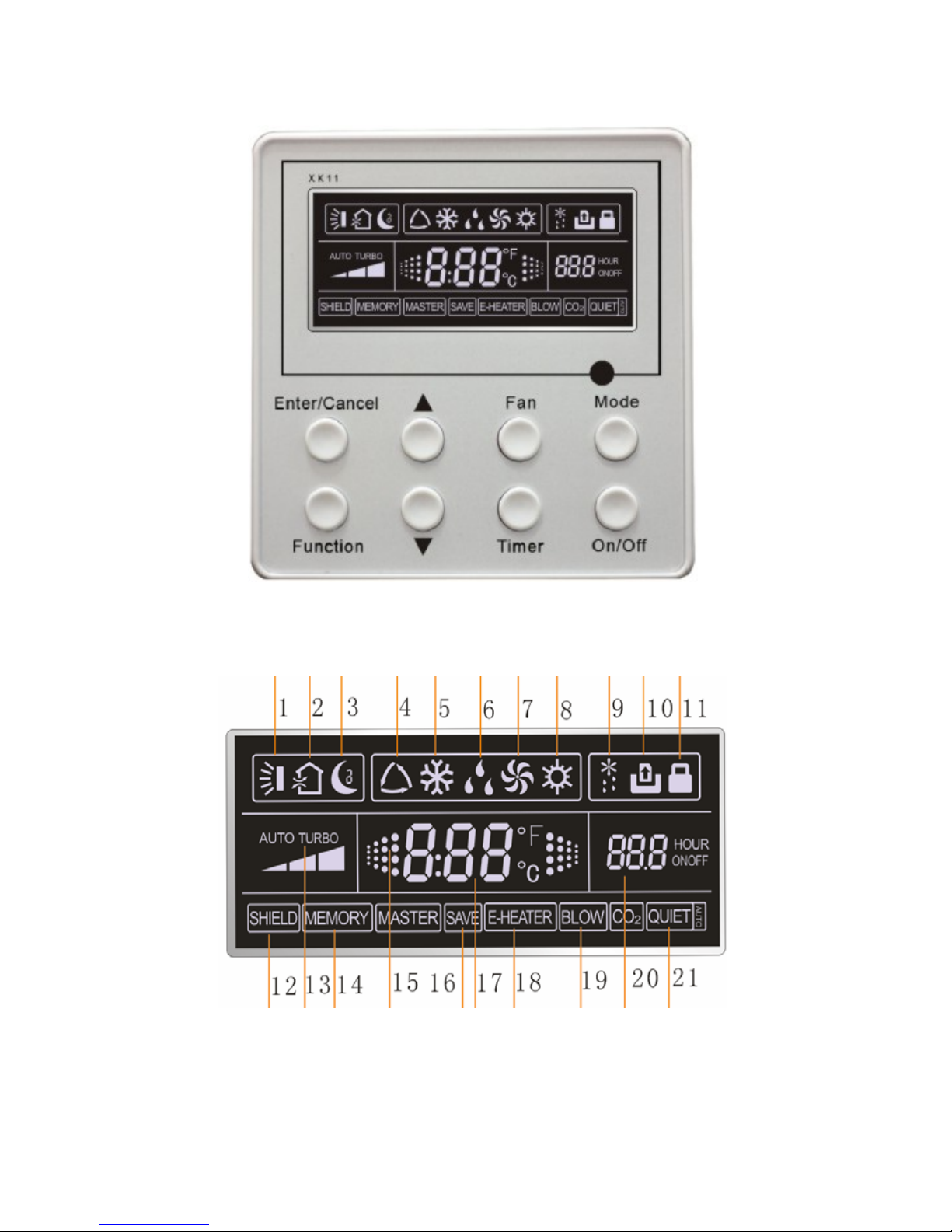
Fig.2 LCD display
4
2.2 Instruction to LCD Display
Table.1
No. Description Instruction to Displaying Contents
1 Swing Swing function
2
Air *
Air exchange function
3 Sleep Sleeping states
4 Running mode Each kind of running mode of indoor unit (auto mode)
5 Cooling Cooling mode
6 Dry Dry mode
7 Fan Fan mode
8 Heating Heating mode
9 Defrost Defrosting state
10
Gate-control card*
Gate control
11 Lock Lock state
12 Shield
Shielding state (buttons, temperature, on/off, mode or save is
shielded by long-distance monitoring
13 Turbo Turbo function state
14 Memory
Memory state (Indoor unit resumes original setting state
after power failure and then power recovery)
15 Twinkle Flicking when unit is on without operation of button
16 Save Energy-saving state
17 Temperature Ambient/setting temperature value
18
E-Heater*
E-HEATER display means electric- heater is available
19 Blow Blow mark
20 Timer Timer-displayed location
21 Quiet Quiet state(two types: quiet and auto quiet)
Notes: The functions with * are reserved for other models and are not applicable for the models
listed in this manual.
5
3. Buttons
Silk Screen of Buttons
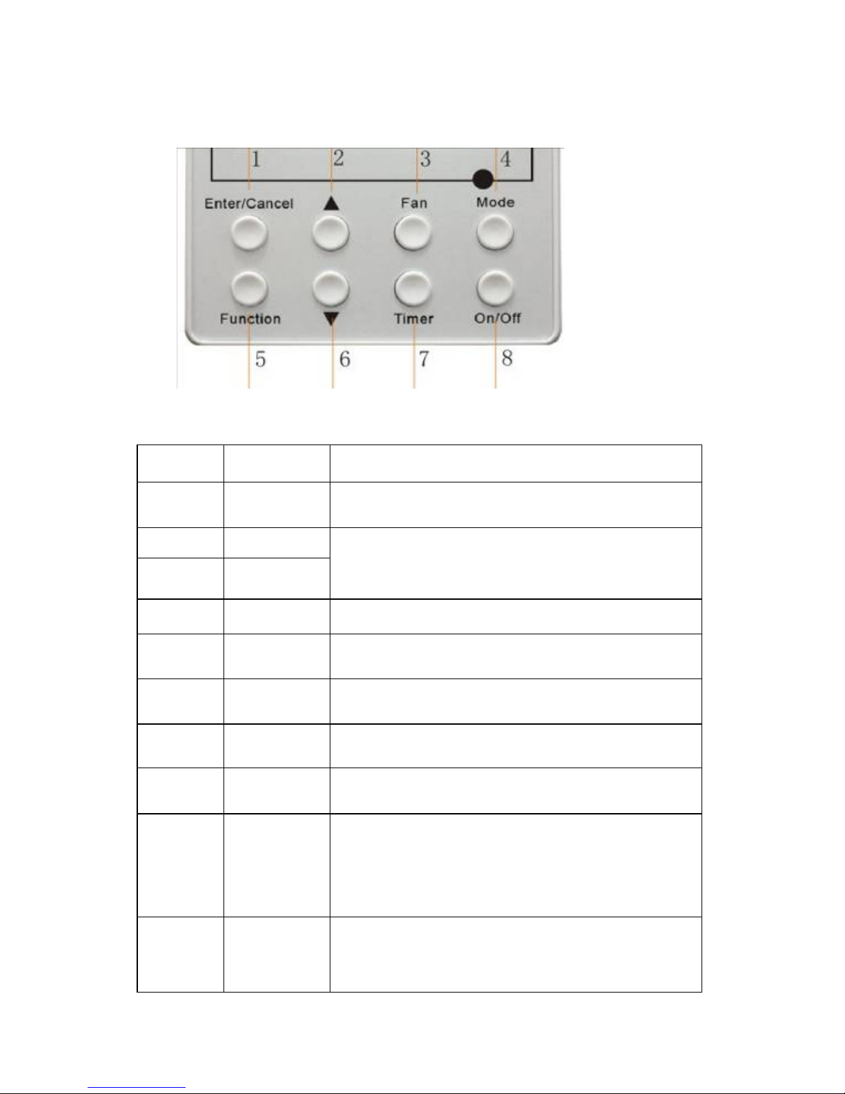
Fig.3 Silk screen of buttons
Instruction to Function of Buttons
Table.2
No. Description Function of Button
1 Enter/cancel
① Function selection and canceling;
② Press it for 5s to enquiry the outdoor ambient temperature.
2 ▲
6 ▼
① Running temperature setting of indoor unit, range :16~
30°C
②Timer setting, range:0.5-24hr
③Switch over between quiet/auto quiet.
3 Fan Setting of high/middle/low/auto fan speed
4 Mode Setting of cooling/heating/fan/dry mode of indoor unit
5 Function
Switchover among these functions of
air/sleep/turbo/save/e-heater/blow/quite
7 Timer Timer setting
8 On/off Turn on/off indoor unit
4 Mode
and
2 ▲
Memory
function
Press Mode and ▲for 5s under off state of the unit to
enter/cancel key memory function (If memory is set, indoor
unit will resume original setting state after power failure and
then power recovery. If not, indoor unit is defaulted to be off
after power recovery. Memory function is defaulted to be off
before outgoing.)
2 ▲
and
6 ▼
Lock
Upon startup of the unit without malfunction or under off state
of the unit, press ▲ ▼ key at the same time for 5s in to lock
state. In this case, any other buttons won’t respond the press.
Repress ▲ ▼ key for 5s to quit lock state.

6
4. Installation of Wired Controller
Fig.4 Sketch for Installation of Wired Controller
No. 1 2 3 4 5
Description Socket’s base
box installed in
the wall
Soleplate of
controller
Screw M4X25 Front panel of
controller
Screw
ST2.2X6.5
Fig.4: Sketch for Installation of Wired Controller. Pay attention to the following items during
installation of wired controller:
1. Cut off power supply of heavy-current wire embedded in mounting hole in the wall before
installation. It is prohibited to perform the whole procedure with electricity.
2. Pull out 4-core twisted pair line in mounting hole and then make it through the rectangle hole at the
back of controller’s soleplate.
3. Joint the controller’s soleplate on wall face and then fix it in mounting hole with screws M4X25.
4. Insert the 4-core twisted pair line through rectangle hole into controller’s slot and buckle the front
panel and soleplate of controller together.
5. At last, fix the controller’s front panel and soleplate with screws ST2.2X6.5.
Caution:
During connection of wirings, pay special attention to the following items to avoid interference of
electromagnetism to unit and even failure of it.
1. To ensure normal communication of the unit, signal line and wiring (communication) of wired
controller should be separate from power cord and indoor/outdoor connection lines. The distance
between them should be kept 20cm in min.
2. If the unit is installed at the place where there is interference of electromagnetism, signal line and
wiring (communication) of wired controller must be shielded by twisted pair lines.
7
5. Instruction to Operation
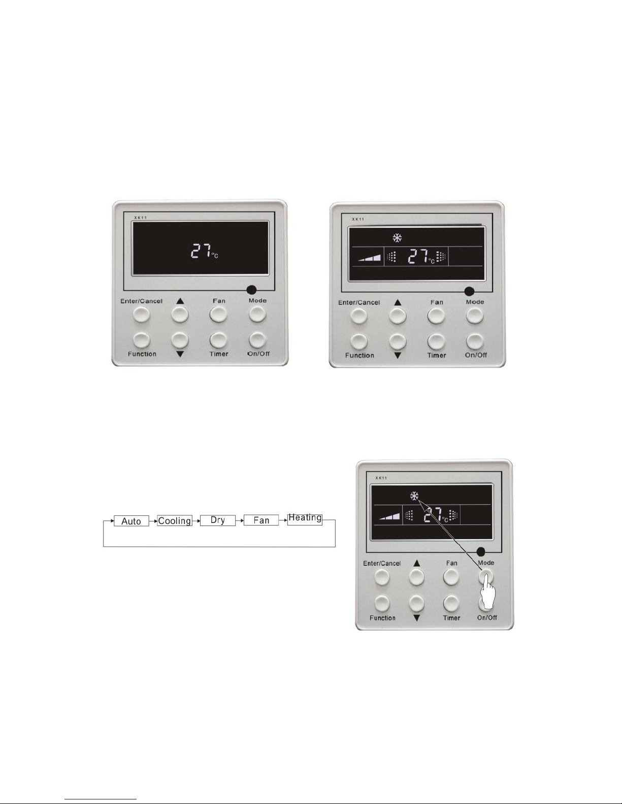
5.1 On/Off
Press On/Off button to turn on the unit.
Repress this button to turn off the unit.
Note: The state shown in Fig.5 indicates off-state of the unit after energizing
The state shown in Fig.6 indicates on-state of the unit after energizing.
Fig.5 Off state of the unit Fig.6 On state of the unit
5.2 Mode Setting
Under on-state of the unit, press Mode button to switch the operation modes as the following
sequence:
Fig.7

8
5.3 Temperature Setting
Press ▲ or ▼button to increase or decrease of setting temperature under on-state of the unit. If
press either of them continuously, temperature will be increased or decreased by 1°C every 0.5s.
In Cooling, Dry, Fan and Heating mode, temperature setting range is 16°C~30°C.
In Auto mode, the setting temperature is un-adjustable.
As shown in Fig.8
Fig.8
5.4 Fan Speed Setting
Press Fan button, fan speed of indoor unit will change as below:
As shown in Fig.9
Fig.9
9
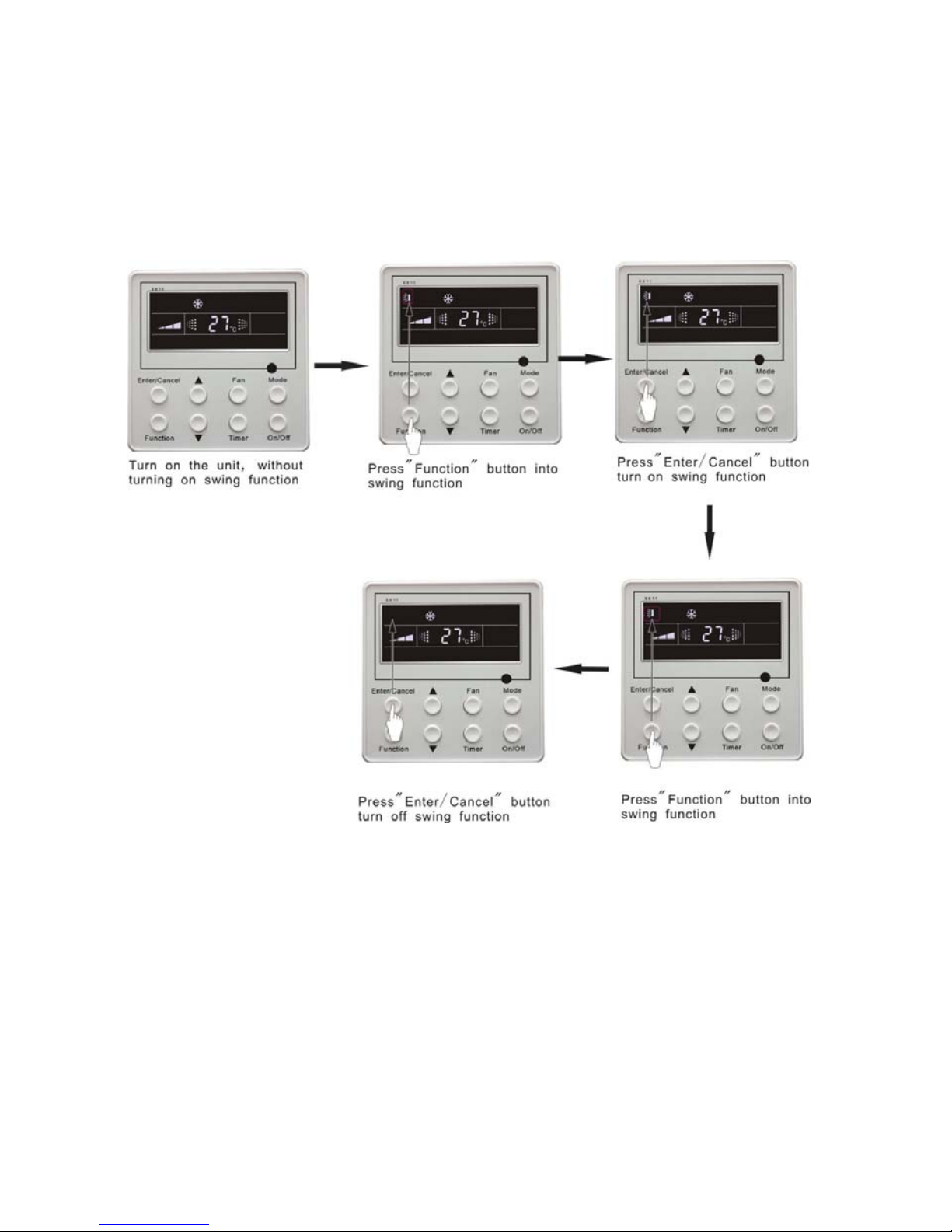
5.5 Swing Control Function
Under on-state of unit, press Function button till the unit enters swing control function and then
press Enter/cancel button to turn on “swing” control function.
During swing function, press Function button till the unit enters swing control function and then
press Enter/cancel button to cancel swing control function.
Swing control function setting is shown in Fig.10
Fig.10
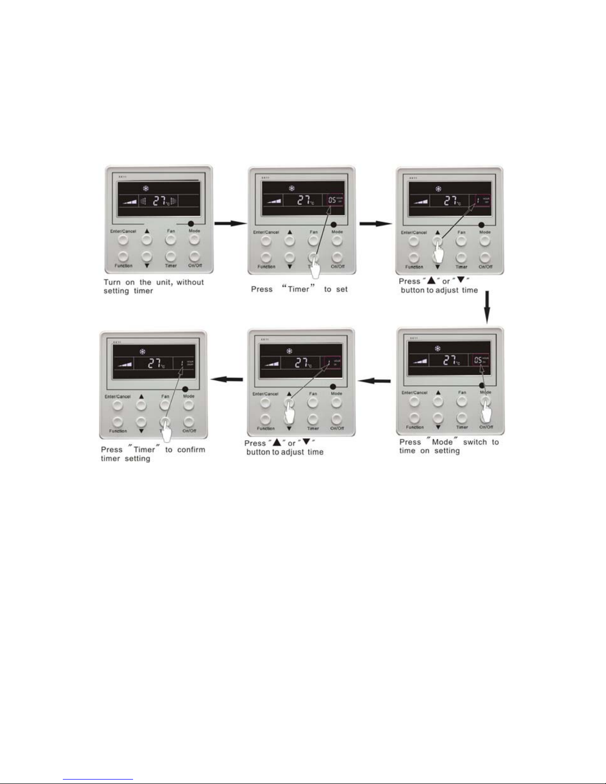
5.6 Timer Setting
Press Timer button to set timer off of the unit. Under off-state of the unit, press Timer button to set
timer on of the unit in the same way.
Timer on setting: Under off-state of the unit without timer setting, if Timer button is pressed,
LCD will display xx hour, with ON blinking. In this case, press▲ or ▼ button to adjust timer on and
then press Timer to confirm. If Mode button is pressed before pressing Timer button to confirm, timer
mode will be switched to timer off setting mode. In this case, LCD displays xx hour, with OFF blinking.
In this case, press▲ or ▼ button to adjust timer off and then press Timer to confirm. When LCD
displays xx hour on off, xx hour means time of timer on, but time of timer off won’t be displayed.
Timer off setting: Under on-state of the unit without timer setting, if Timer button is pressed, LCD
10
will display xx hour, with OFF blinking. In this case, press▲ or ▼ button to adjust timer on and then
press Timer to confirm. If Mode button is pressed before pressing Timer button to confirm, timer mode
will be switched to timer on setting mode. In this case, LCD displays xx hour, with ON blinking. In this
case, press▲ or ▼ button to adjust timer on and then press Timer button to confirm. When LCD
displays xx hour on off, xx hour means time of timer off, but time of timer on won’t be displayed.
Cancel timer: After setting of timer, if Timer button is pressed, LCD won’t display xx. Hour so
that timer setting is canceled.
Timer off setting under on-state of the unit is shown as Fig.11
Fig.11 Timer setting under on state of the unit
Timer range: 0.5-24hr. Every press of▲ or ▼ button will make setting time increased or
decreased by 0.5hr.If press either of them continuously, setting time will automatically increase/
decrease by 0.5hr every 0.5s.
Note:
1. If both timer on and timer off are set in unit on interface, the wired controller only display time of
time off. If both of them are set in unit off-state, only time of timer on is displayed.
2. Timer on in unit on-state is timed from the time of unit off and timer off in unit off-state is timed
from the time of unit on.
11
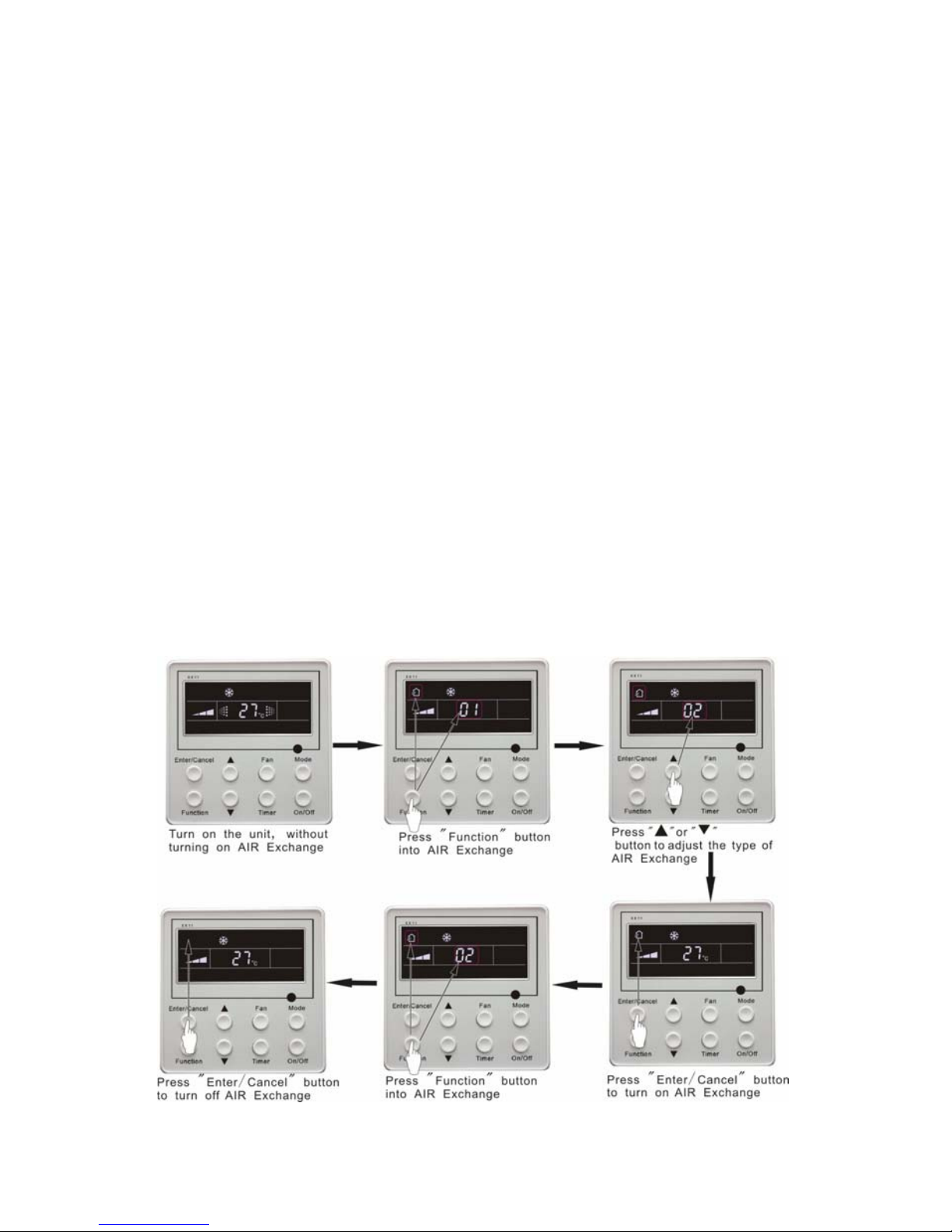
5.7 Air Exchange Setting*
Turn on air Exchange function:
Under on-state of the unit, press Function button to go to this function setting (Air mark
blinks).AIR 1 displayed at the ambient temperature-displayed location (888) is defaulted (the last type
of AIR will be displayed after adjustment).Press ▲ or ▼ button to adjust air type. Press Enter/Cancel
button to turn on/off air function. After turning on this function, the air mark shows.
There are 10 types of AIR, but only 1-2 types are for remote control. Refer to the following details:
1――The unit continuously runs for 60min, and fresh air valve runs for 6 min.
2――The unit continuously runs for 60min, and fresh air valve runs for 12 min.
3――The unit continuously runs for 60min, and fresh air valve runs for 18 min.
4――The unit continuously runs for 60min, and fresh air valve runs for 2 4 min.
5――The unit continuously runs for 60min, and fresh air valve runs for 30 min.
6――The unit continuously runs for 60min, and fresh air valve runs for 36 min.
7――The unit continuously runs for 60min, and fresh air valve runs for 42 min.
8――The unit continuously runs for 60min, and fresh air valve runs for 48 min.
9――The unit continuously runs for 60min, and fresh air valve runs for 54 min.
10――The unit continuously runs for 60min, and fresh air valve always runs.
Turn off air Exchange function: During Air function, press Function button to go to the Air
function. In this case, air mark is blinking, and then press Enter/cancel button to turn off this function.
Air mark will subsequently disappear.
Air Exchange setting is shown as in Fig.12:
Fig.12 Air exchange device
12
Note:
In air exchange mode, press Function button or there is not any operation within 5s after the last
button operation, the system will be quit from air exchange setting and current energy-saving data won’t
be memorized.
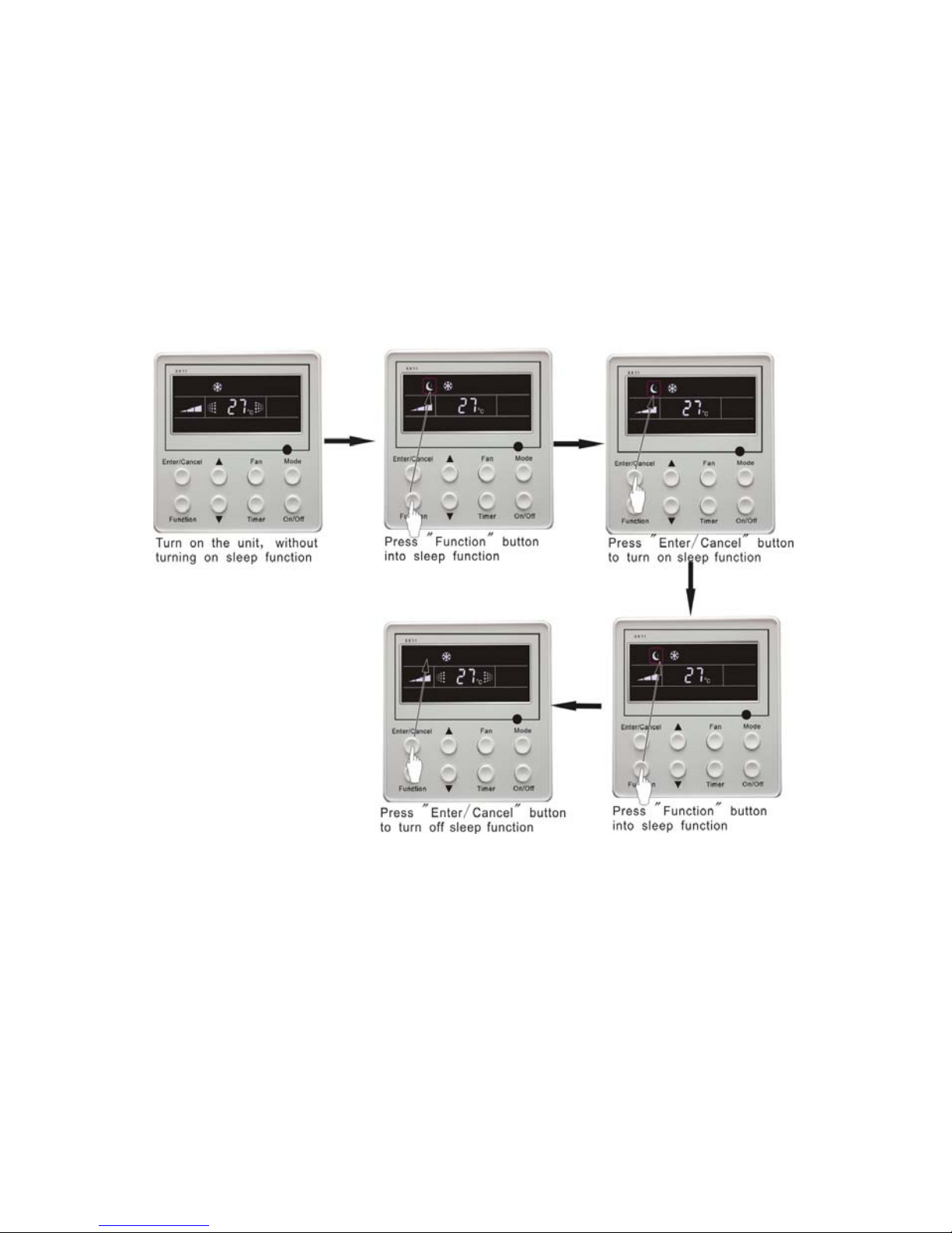
5.8 Sleep Setting
Sleep on: Press Function button under on-state of the unit into sleep function and then press
Enter/cancel button to turn on sleeping function.
Sleep off: During sleep on-state, press Function button to go to the sleep function and then press
Enter/cancel button to turn off this function.
Sleep setting is shown as Fig.13:
Fig.13 Sleep setting
Sleep setting is clear after power failure and then power recovery. There is not sleep function in fan
and auto mode.
Note:
In cooling and dry mode, if the unit with sleep function has run for 1 hour, the preset temperature
will be increased by 1°C and 1°C in another 1 hour. After that, the unit will run at this temperature. In
heating mode, if the unit with sleep function has run for 1 hour, the preset temperature will be decreased
by 1°C and 1°C in another 1 hour. After that, the unit will run at this temperature.
13
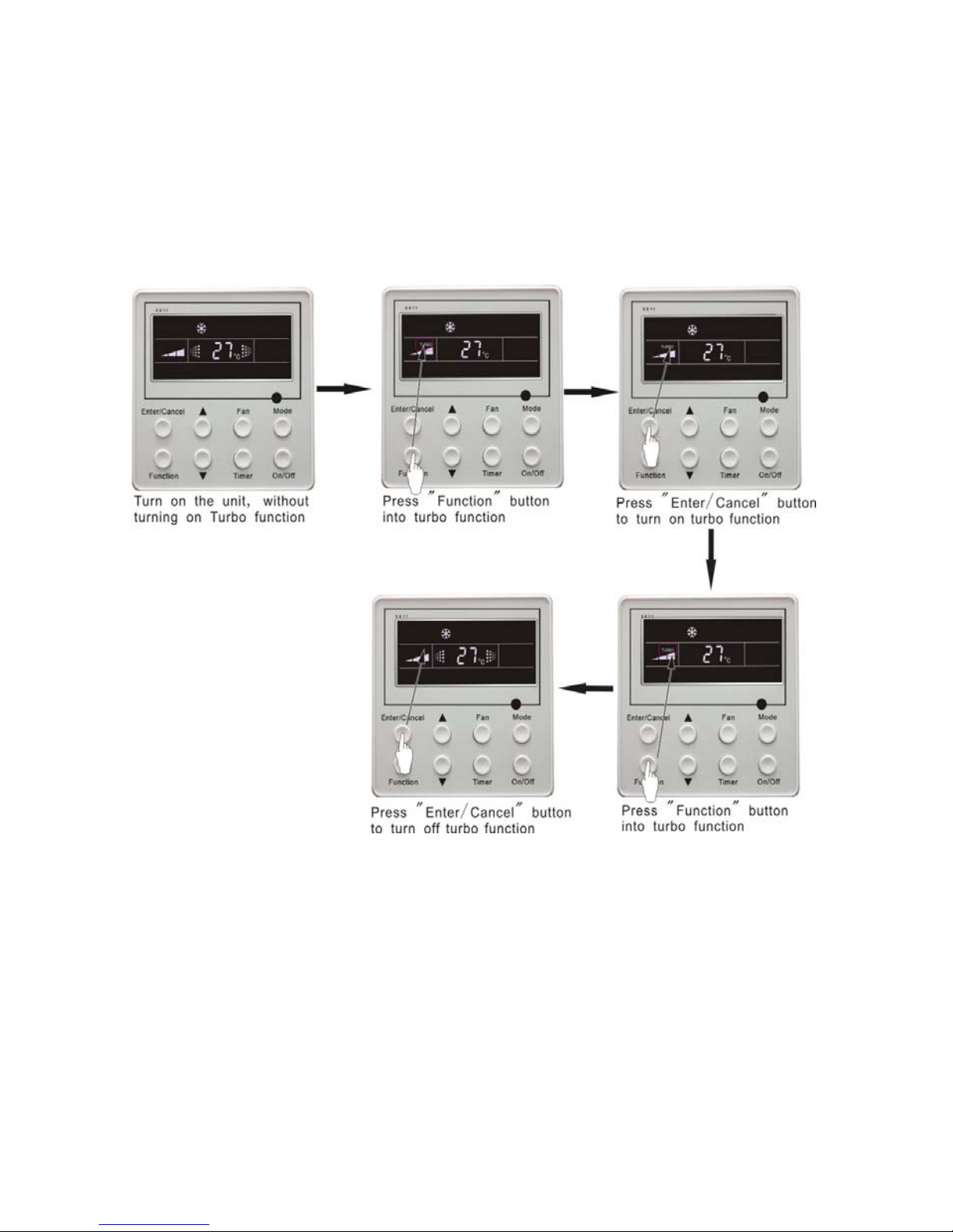
5.9 Turbo Function Setting
TURBO function: The unit at high fun speed can realize quick cooling or heating so that room
temperature can quickly approach setting temperature.
In cooling or heating mode, press Function button till the unit enters TURBO function and then
press Enter/cancel button to turn on TURBO function.
During TURBO function, press Function button till the unit enters TURBO function and then
press Enter/cancel button to cancel TURBO function.
TURBO function setting is shown in Fig.14:
Fig.14 Turbo Function Setting
Note:
1. TURBO function will be turned off after power failure and then recovery. In dry, fan and auto mode,
TURBO function can not be set and TURBO mark won’t be displayed.
2. TURBO function will be automatically canceled after setting of quiet function.
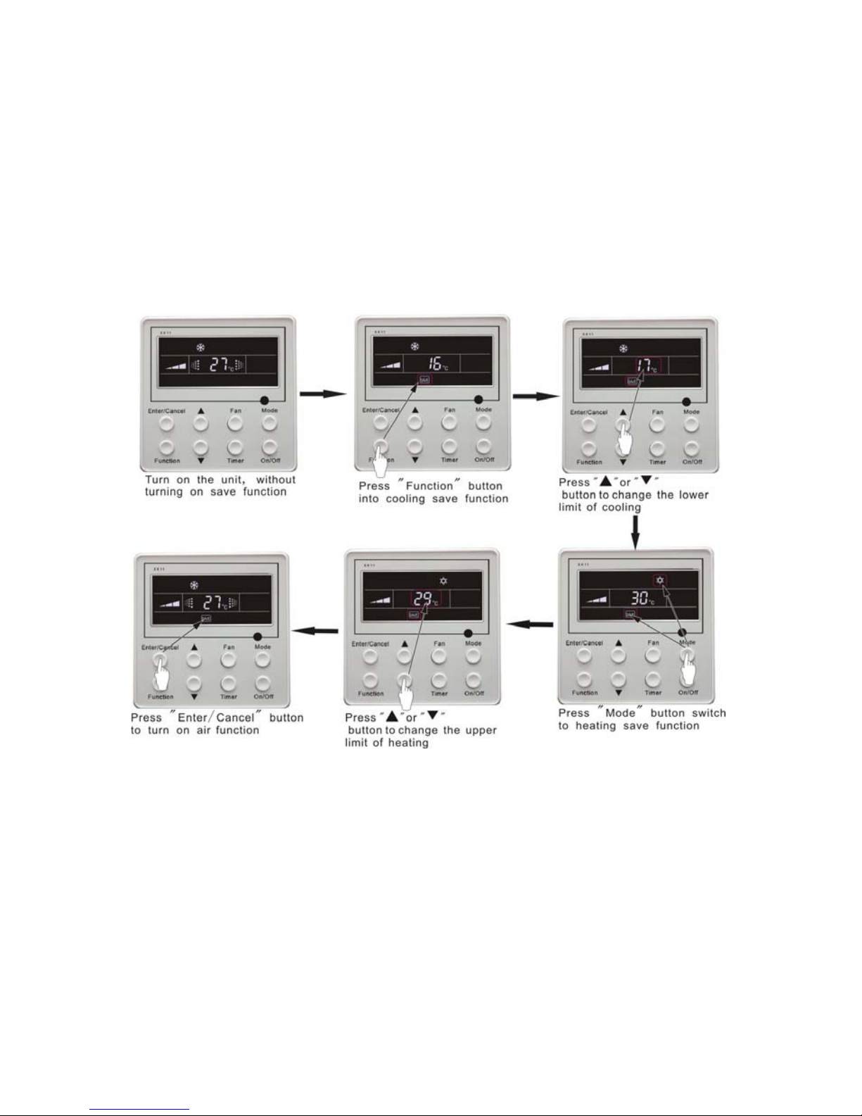
5.10 SAVE Function Setting
Energy Saving Function: Energy saving can make the air conditioner runs in a smaller temperature
range by setting lower limited value of setting temperature in cooling or dry mode and upper limited
value in heating mode.
14
Energy Saving Setting for Cooling
Under on-state and in cooling or dry mode of the unit, press Function button into energy saving
function, with SAVE blinking .Press ▲ or ▼ button to adjust lower limited value of setting temperature
in cooing mode. After that press Enter/Cancel button to turn on energy saving function for cooling.
Energy Saving Setting for Heating
Under on state and in heating mode of the unit, press Function button into energy saving function,
with SAVE blinking. Press Mode button into energy saving function for heating and then press▲ or ▼
button to adjust upper limited value of setting temperature in heating mode. After that, press
Enter/Cancel button to turn on energy saving function for heating.
After energy saving function is turned on, press Function button into energy saving function and
press Enter/cancel to cancel this function.
The energy saving setting is shown in the Fig.15:
Fig.15 Energy Saving Setting
Note:
1. In Auto running mode with save function on, the unit will be forcibly quit Auto running Mode and
change to current operation mode, After setting of save, sleep function will be canceled.
2. In save mode, if Function button is pressed or there is not any operation within 5s after the last
button operation, the system will be quit from save function setting and current data won’t be
memorized.
3. After power failure and then recovery, save function setting will be memorized.
4. The lower limited value in cooling mode is 16°C and the upper limited value in heating mode is
30°C.
5. After save setting, if the setting temperature is out of the range in the mode, the limited value will
prevail.
 Loading...