


Split Type Floor Ceiling Air Conditioner
V1KI-09
V1KI-12
V1KI-18
V1KI-24
V1KI-30
V1KI-36
V1KI-45
V1KI-50
V1KI-60


Contents
1. Safety Considerations....................................................................................1
2. Displaying Part...............................................................................................3
2.1 LCD Display of Wired controller .........................................................................3
2.2 Instruction to LCD Display ..................................................................................4
3. Buttons............................................................................................................5
4. Installation of Wired Controller...................................................................6
5. Instruction to Operation................................................................................7
5.1 On/Off..................................................................................................................7
5.2 Mode Setting........................................................................................................7
5.3 Temperature Setting .............................................................................................8
5.4 Fan Speed Setting.................................................................................................8
5.5 Swing Control Function .......................................................................................9
5.6 Timer Setting........................................................................................................9
5.7 Air Exchange Setting*......................................................................................11
5.8 Sleep Setting ......................................................................................................12
5.9 Turbo Function Setting.......................................................................................13
5.10 SAVE Function Setting ....................................................................................13
5.11 E-HEATER Setting* ........................................................................................15
5.12 Blow Function Setting........................................................................................16
5.13 Quiet Function Setting .......................................................................................17
5.14 Field Functions...................................................................................................18
5.15 Other Functions..................................................................................................18
6. Error Display................................................................................................20
7. Remote control operation procedure(standard fitting) ............................23
8. Part Names and Their Functions................................................................33
9. Maintenance.................................................................................................34
10. Operating Guide ......................................................................................35
11. Precautions...............................................................................................36
12. Checking Before Contact the Service Man............................................37
12.1 Accessories List for Installation.........................................................................37
12.2 Installation of the Indoor Unit............................................................................39

12.3 Installation of the Outdoor Unit .........................................................................42
12.4 Schematic Diagram of Unit Line Connection ....................................................45
12.5 Connecting Pipe Preparation..............................................................................48
13. Appendix...................................................................................................55
1
1. Safety Considerations
Please read this manual carefully before use and operate correctly as instructed in the manual.
You are specially warned to note the two symbols below.
CAUTION! :
A symbol indicating that improper operation might cause human death or severe
injury.
WARNING! :
A symbol indicating that improper operation might cause human property damage.
WARNING!
1. This unit should be used in offices, restaurants, residences or similar places.
2. Please seek an authorized repair station for installation work. Improper installation might cause
water leakage, electric shock or fire.
3. Please install at a place strong enough to support the weight of air conditioner unit. Otherwise, the
air conditioner unit might fall down and cause human injury or death.
4. To ensure proper drainage, the drainage pipe should be correctly installed according to installation
instructions. Take proper measures for heat preservation to prevent condensing. Improper
installation of pipes might cause leakage and wet the articles in the room.
5. Do not use or store flammable, explosive, poisonous or other dangerous substances beside the air
conditioner.
6. In case of troubles (e.g. burnt smell), please immediately cut off the main power of air conditioner
unit.
7. Keep air flow to avoid shortage of oxygen in the room.
8. Never insert your finger or any objects into the air outlet or the inlet grill.
9. Never plug or unplug the power cable directly to start or stop the air-conditioning unit.
10. Please take constant care to check if the mounting rack is damaged after long time use.
11. Never modify the air conditioner. Please contact the dealer or professional installation workers for
repair or relocation of the air conditioner.
12. The appliance should not be installed in the laundry.
13. Before installation, please check the power supply for compliance with the ratings on nameplate.
Check the power safety as well. (By professionals)
14. Before use, please check and confirm if the cables, drainage pipes and pipelines are correctly
connected, hence to eliminate the risk of water leakage, refrigerant leakage, electric shock or fire.
15. Main power must be securely earthed to ensure effective grounding of the air conditioner unit and
avoid the risk of electric shock. Please do not connect the earth cable to coal gas pipe, water pipe,
lightning rod or telephone line.
16. Once started, the air conditioner should not be stopped until at least five minutes later. Otherwise
the oil return to the compressor may be affected.
17. Do not let the child operate the air conditioner unit.
18. Do not operate the air conditioner unit with wet hands.
19. Please disconnect the main power before cleaning the air conditioner or replacing the air filter. (By
professionals)
20. Please disconnect the main power if the air conditioner is not to be used for al long period of time.
21. Please do not expose the air conditioner unit directly in corrosive environment with water or
moisture.

2
22. Please do not foot on or place any goods on air conditioner unit.
23. After electrical installation, the air conditioner unit should be energized for electrical leakage test.
(By professionals)
24. If the supply cord is damaged, it must be replaced by the manufacturer or its service agent or a
similarly qualified person in order to avoid a hazard.
25. An all-pole disconnection switch with a contact separation of at least 3mm in all poles should be
connected with the fixed wiring.
26. The appliance should be installed in accordance with national wiring regulations.
27. Keep the interconnection cable away from the cooper tube due to the high temperature of the
refrigerant circuit.
28. The power cord must be separated with the communication line.
29. This appliance is not intended for use by persons (including children) with reduced physical,
sensory or mental capabilities, or lack of experience and knowledge, unless they have been given
supervision or instruction concerning use of the appliance by a person responsible for their safety.
30. Children should be supervised to ensure that they do not play with the appliance.
3
2. Displaying Part
Fig.1 Outline of wired controller
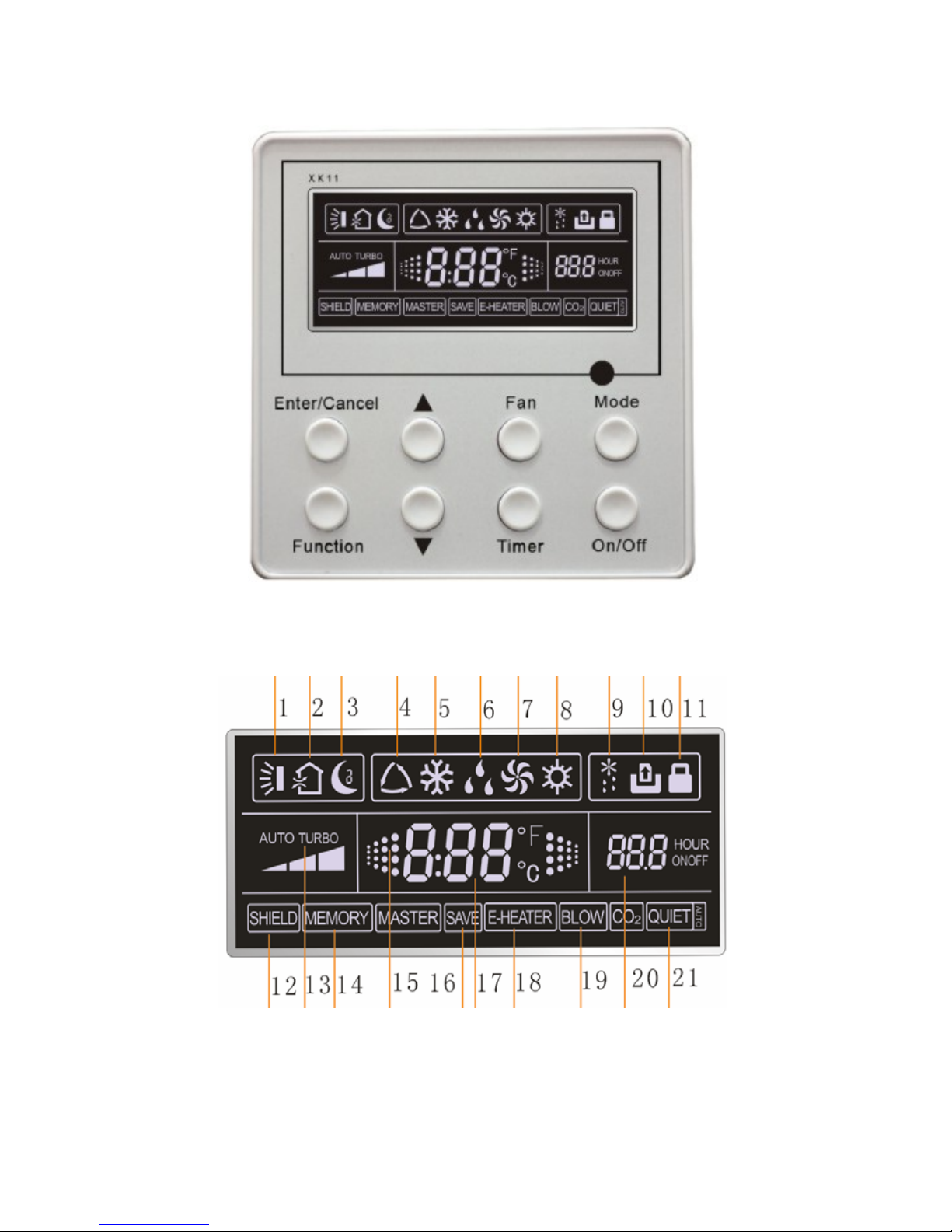
2.1 LCD Display of Wired controller
Fig.2 LCD display
4
2.2 Instruction to LCD Display
Table.1
No. Description Instruction to Displaying Contents
1 Swing Swing function
2
Air *
Air exchange function
3 Sleep Sleeping states
4 Running mode Each kind of running mode of indoor unit (auto mode)
5 Cooling Cooling mode
6 Dry Dry mode
7 Fan Fan mode
8 Heating Heating mode
9 Defrost Defrosting state
10
Gate-control card*
Gate control
11 Lock Lock state
12 Shield
Shielding state (buttons, temperature, on/off, mode or save is
shielded by long-distance monitoring
13 Turbo Turbo function state
14 Memory
Memory state (Indoor unit resumes original setting state
after power failure and then power recovery)
15 Twinkle Flicking when unit is on without operation of button
16 Save Energy-saving state
17 Temperature Ambient/setting temperature value
18
E-Heater*
E-HEATER display means electric- heater is available
19 Blow Blow mark
20 Timer Timer-displayed location
21 Quiet Quiet state(two types: quiet and auto quiet)
Notes: The functions with * are reserved for other models and are not applicable for the models
listed in this manual.
5
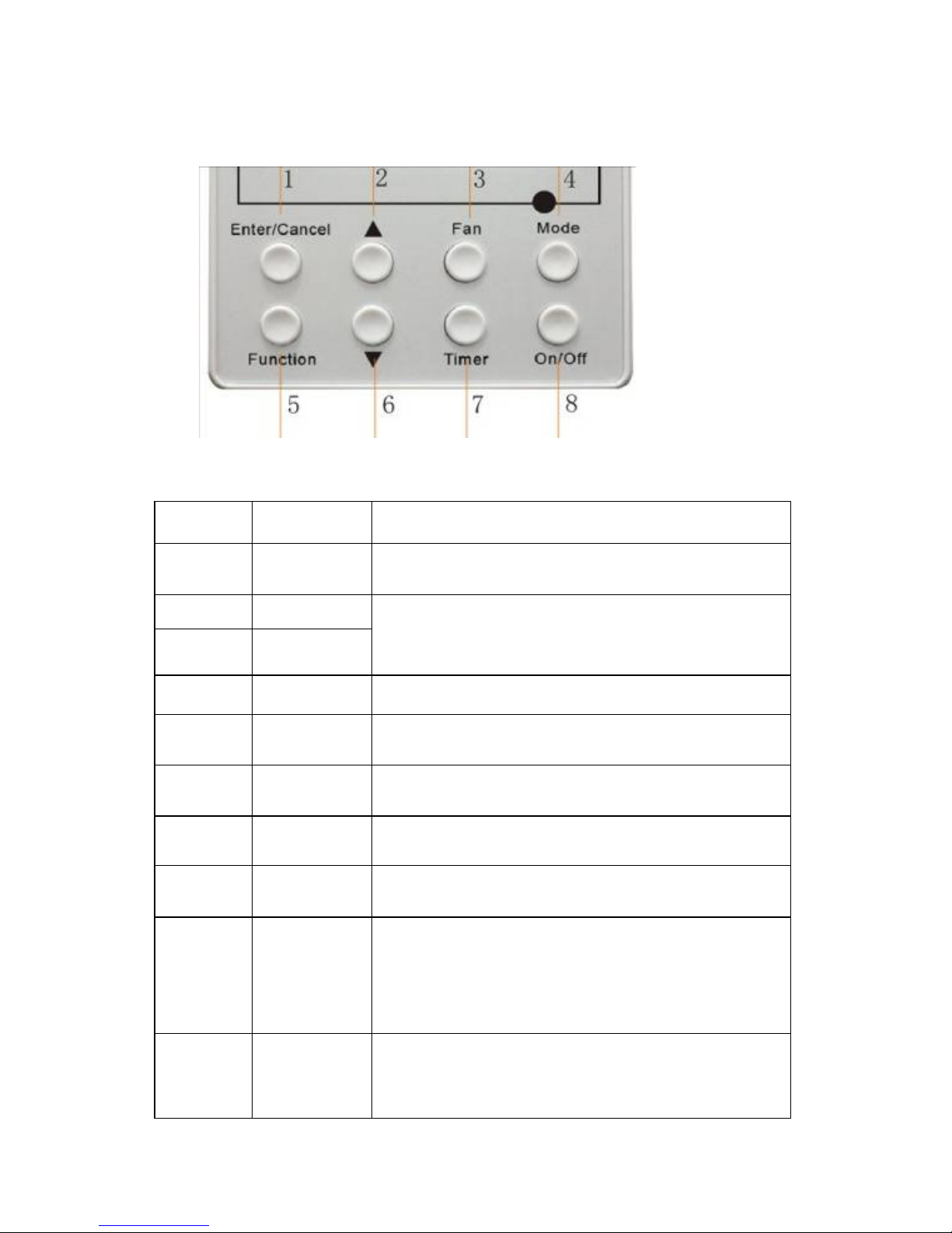
3. Buttons
Silk Screen of Buttons
Fig.3 Silk screen of buttons
Instruction to Function of Buttons
Table.2
No. Description Function of Button
1 Enter/cancel
① Function selection and canceling;
② Press it for 5s to enquiry the outdoor ambient temperature.
2 ▲
6 ▼
① Running temperature setting of indoor unit, range :16~
30°C
②Timer setting, range:0.5-24hr
③Switch over between quiet/auto quiet.
3 Fan Setting of high/middle/low/auto fan speed
4 Mode Setting of cooling/heating/fan/dry mode of indoor unit
5 Function
Switchover among these functions of
air/sleep/turbo/save/e-heater/blow/quite
7 Timer Timer setting
8 On/off Turn on/off indoor unit
4 Mode
and
2 ▲
Memory
function
Press Mode and ▲for 5s under off state of the unit to
enter/cancel key memory function (If memory is set, indoor
unit will resume original setting state after power failure and
then power recovery. If not, indoor unit is defaulted to be off
after power recovery. Memory function is defaulted to be off
before outgoing.)
2 ▲
and
6 ▼
Lock
Upon startup of the unit without malfunction or under off state
of the unit, press ▲ ▼ key at the same time for 5s in to lock
state. In this case, any other buttons won’t respond the press.
Repress ▲ ▼ key for 5s to quit lock state.

6
4. Installation of Wired Controller
Fig.4 Sketch for Installation of Wired Controller
No. 1 2 3 4 5
Description Socket’s base
box installed in
the wall
Soleplate of
controller
Screw M4X25 Front panel of
controller
Screw
ST2.2X6.5
Fig.4: Sketch for Installation of Wired Controller. Pay attention to the following items during
installation of wired controller:
1. Cut off power supply of heavy-current wire embedded in mounting hole in the wall before
installation. It is prohibited to perform the whole procedure with electricity.
2. Pull out 4-core twisted pair line in mounting hole and then make it through the rectangle hole at the
back of controller’s soleplate.
3. Joint the controller’s soleplate on wall face and then fix it in mounting hole with screws M4X25.
4. Insert the 4-core twisted pair line through rectangle hole into controller’s slot and buckle the front
panel and soleplate of controller together.
5. At last, fix the controller’s front panel and soleplate with screws ST2.2X6.5.
Caution:
During connection of wirings, pay special attention to the following items to avoid interference of
electromagnetism to unit and even failure of it.
1. To ensure normal communication of the unit, signal line and wiring (communication) of wired
controller should be separate from power cord and indoor/outdoor connection lines. The distance
between them should be kept 20cm in min.
2. If the unit is installed at the place where there is interference of electromagnetism, signal line and
wiring (communication) of wired controller must be shielded by twisted pair lines.
7
5. Instruction to Operation
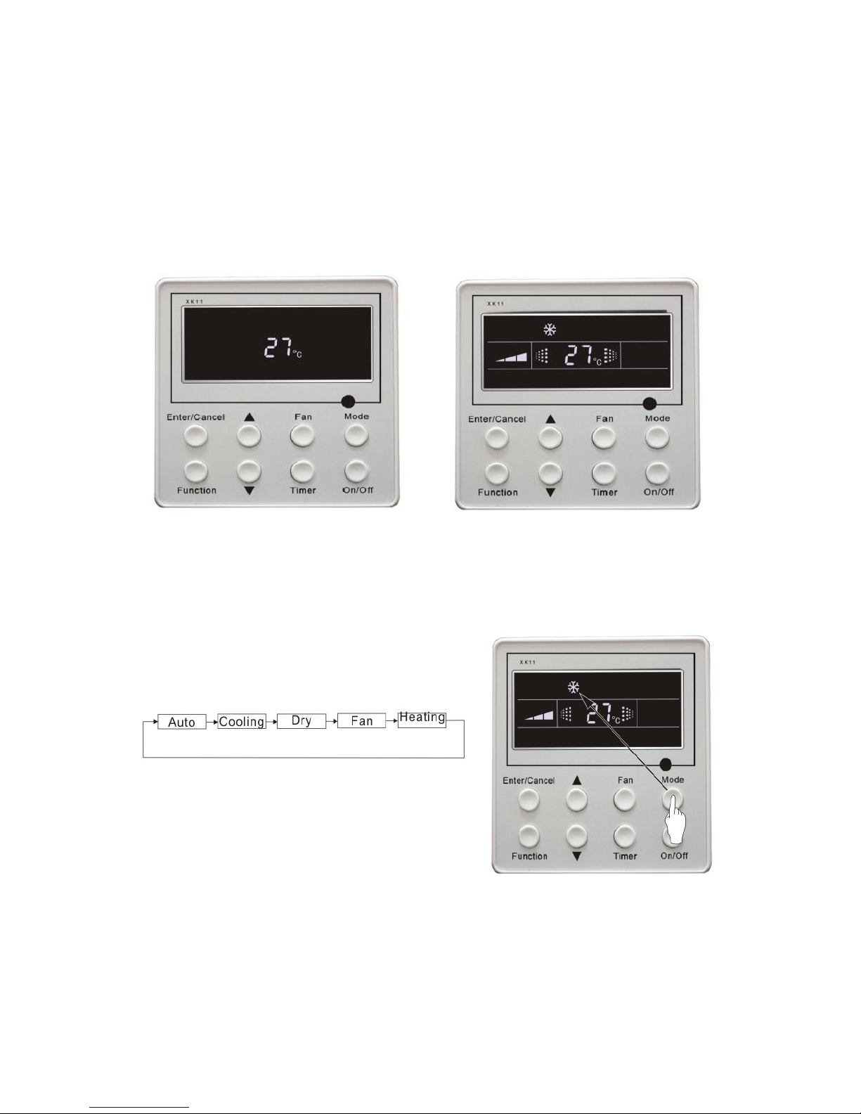
5.1 On/Off
Press On/Off button to turn on the unit.
Repress this button to turn off the unit.
Note: The state shown in Fig.5 indicates off-state of the unit after energizing
The state shown in Fig.6 indicates on-state of the unit after energizing.
Fig.5 Off state of the unit Fig.6 On state of the unit
5.2 Mode Setting
Under on-state of the unit, press Mode button to switch the operation modes as the following
sequence:
Fig.7

8
5.3 Temperature Setting
Press ▲ or ▼button to increase or decrease of setting temperature under on-state of the unit. If
press either of them continuously, temperature will be increased or decreased by 1°C every 0.5s.
In Cooling, Dry, Fan and Heating mode, temperature setting range is 16°C~30°C.
In Auto mode, the setting temperature is un-adjustable.
As shown in Fig.8
Fig.8
5.4 Fan Speed Setting
Press Fan button, fan speed of indoor unit will change as below:
As shown in Fig.9
Fig.9
9
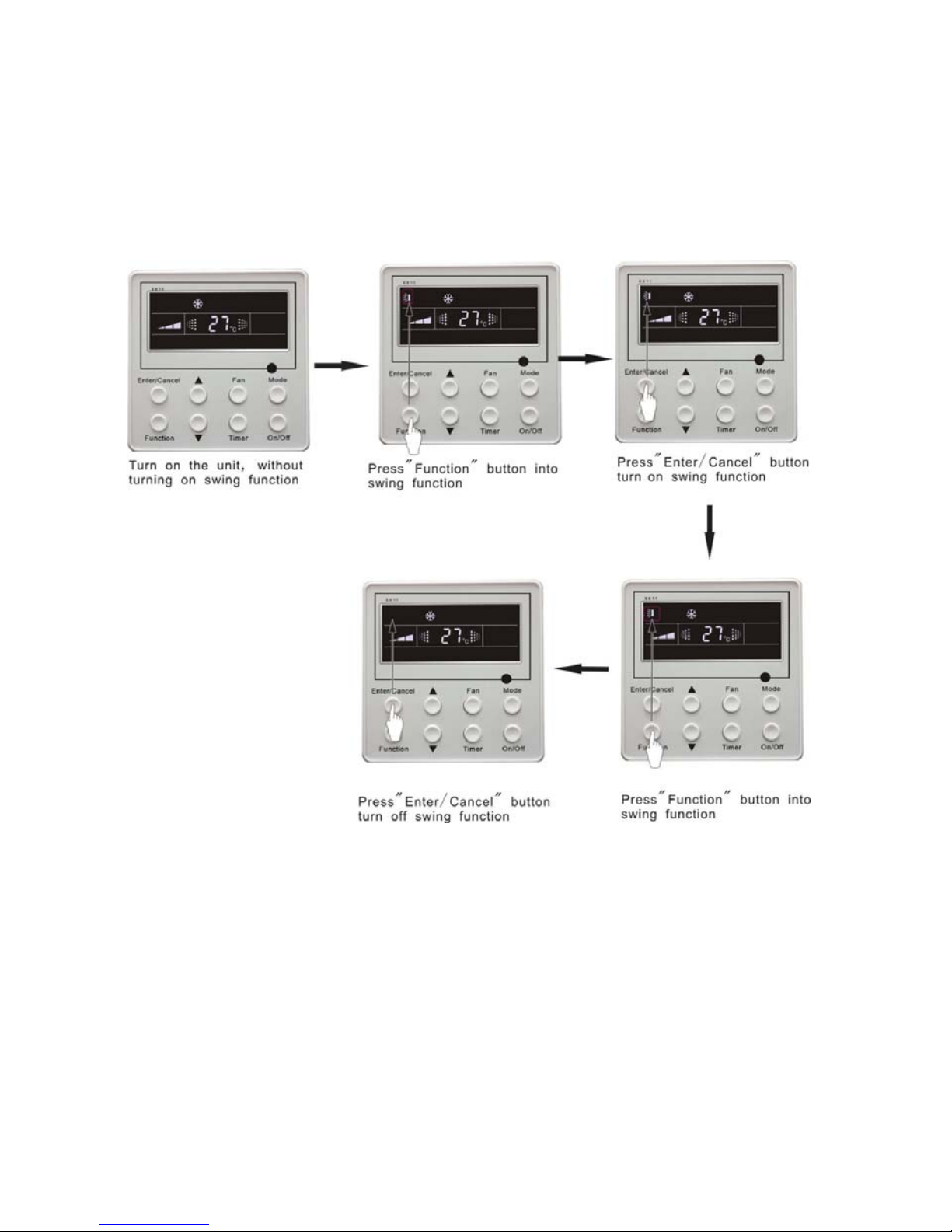
5.5 Swing Control Function
Under on-state of unit, press Function button till the unit enters swing control function and then
press Enter/cancel button to turn on “swing” control function.
During swing function, press Function button till the unit enters swing control function and then
press Enter/cancel button to cancel swing control function.
Swing control function setting is shown in Fig.10
Fig.10
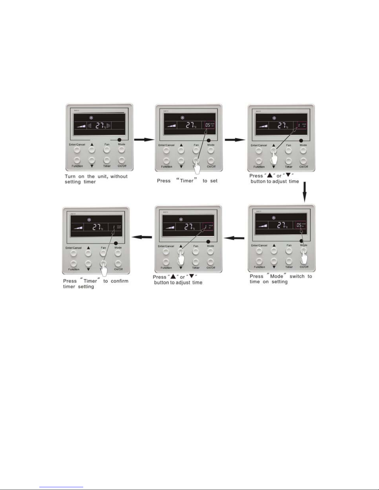
5.6 Timer Setting
Press Timer button to set timer off of the unit. Under off-state of the unit, press Timer button to set
timer on of the unit in the same way.
Timer on setting: Under off-state of the unit without timer setting, if Timer button is pressed,
LCD will display xx hour, with ON blinking. In this case, press▲ or ▼ button to adjust timer on and
then press Timer to confirm. If Mode button is pressed before pressing Timer button to confirm, timer
mode will be switched to timer off setting mode. In this case, LCD displays xx hour, with OFF blinking.
In this case, press▲ or ▼ button to adjust timer off and then press Timer to confirm. When LCD
displays xx hour on off, xx hour means time of timer on, but time of timer off won’t be displayed.
Timer off setting: Under on-state of the unit without timer setting, if Timer button is pressed, LCD
10
will display xx hour, with OFF blinking. In this case, press▲ or ▼ button to adjust timer on and then
press Timer to confirm. If Mode button is pressed before pressing Timer button to confirm, timer mode
will be switched to timer on setting mode. In this case, LCD displays xx hour, with ON blinking. In this
case, press▲ or ▼ button to adjust timer on and then press Timer button to confirm. When LCD
displays xx hour on off, xx hour means time of timer off, but time of timer on won’t be displayed.
Cancel timer: After setting of timer, if Timer button is pressed, LCD won’t display xx. Hour so
that timer setting is canceled.
Timer off setting under on-state of the unit is shown as Fig.11
Fig.11 Timer setting under on state of the unit
Timer range: 0.5-24hr. Every press of▲ or ▼ button will make setting time increased or
decreased by 0.5hr.If press either of them continuously, setting time will automatically increase/
decrease by 0.5hr every 0.5s.
Note:
1. If both timer on and timer off are set in unit on interface, the wired controller only display time of
time off. If both of them are set in unit off-state, only time of timer on is displayed.
2. Timer on in unit on-state is timed from the time of unit off and timer off in unit off-state is timed
from the time of unit on.
11
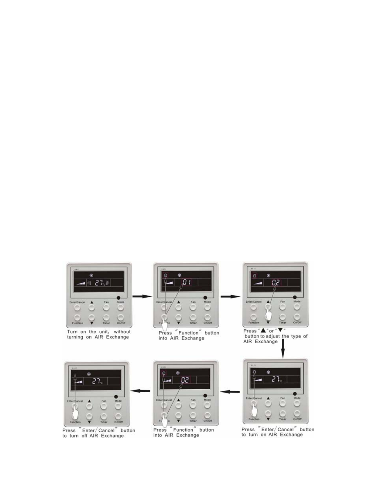
5.7 Air Exchange Setting*
Turn on air Exchange function:
Under on-state of the unit, press Function button to go to this function setting (Air mark
blinks).AIR 1 displayed at the ambient temperature-displayed location (888) is defaulted (the last type
of AIR will be displayed after adjustment).Press ▲ or ▼ button to adjust air type. Press Enter/Cancel
button to turn on/off air function. After turning on this function, the air mark shows.
There are 10 types of AIR, but only 1-2 types are for remote control. Refer to the following details:
1――The unit continuously runs for 60min, and fresh air valve runs for 6 min.
2――The unit continuously runs for 60min, and fresh air valve runs for 12 min.
3――The unit continuously runs for 60min, and fresh air valve runs for 18 min.
4――The unit continuously runs for 60min, and fresh air valve runs for 2 4 min.
5――The unit continuously runs for 60min, and fresh air valve runs for 30 min.
6――The unit continuously runs for 60min, and fresh air valve runs for 36 min.
7――The unit continuously runs for 60min, and fresh air valve runs for 42 min.
8――The unit continuously runs for 60min, and fresh air valve runs for 48 min.
9――The unit continuously runs for 60min, and fresh air valve runs for 54 min.
10――The unit continuously runs for 60min, and fresh air valve always runs.
Turn off air Exchange function: During Air function, press Function button to go to the Air
function. In this case, air mark is blinking, and then press Enter/cancel button to turn off this function.
Air mark will subsequently disappear.
Air Exchange setting is shown as in Fig.12:
Fig.12 Air exchange device
12
Note:
In air exchange mode, press Function button or there is not any operation within 5s after the last
button operation, the system will be quit from air exchange setting and current energy-saving data won’t
be memorized.
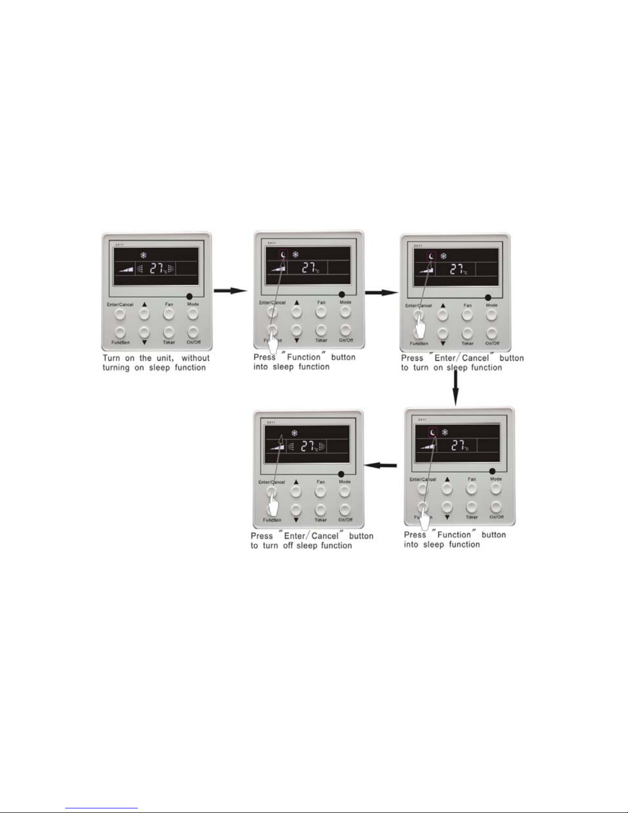
5.8 Sleep Setting
Sleep on: Press Function button under on-state of the unit into sleep function and then press
Enter/cancel button to turn on sleeping function.
Sleep off: During sleep on-state, press Function button to go to the sleep function and then press
Enter/cancel button to turn off this function.
Sleep setting is shown as Fig.13:
Fig.13 Sleep setting
Sleep setting is clear after power failure and then power recovery. There is not sleep function in fan
and auto mode.
Note:
In cooling and dry mode, if the unit with sleep function has run for 1 hour, the preset temperature
will be increased by 1°C and 1°C in another 1 hour. After that, the unit will run at this temperature. In
heating mode, if the unit with sleep function has run for 1 hour, the preset temperature will be decreased
by 1°C and 1°C in another 1 hour. After that, the unit will run at this temperature.
13
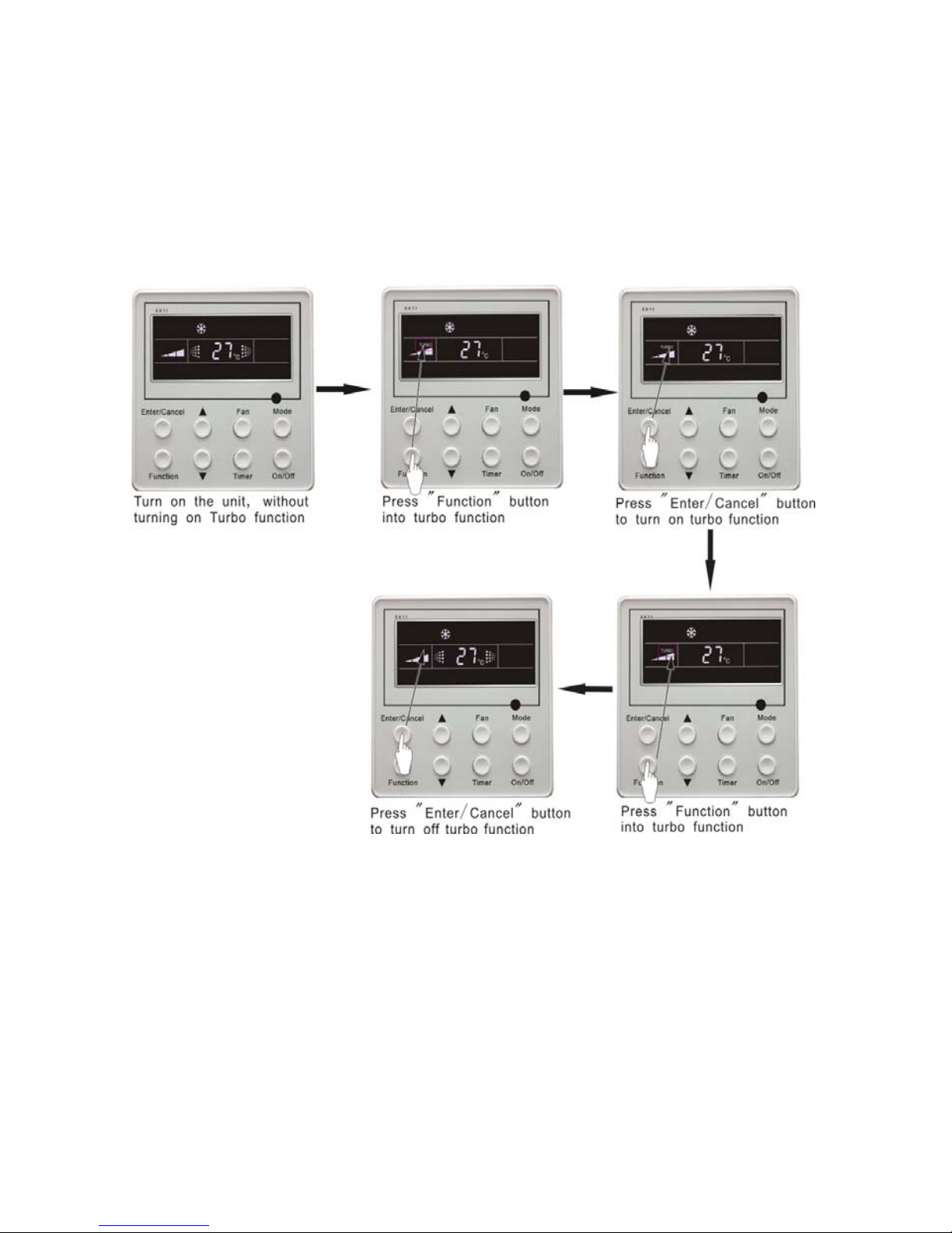
5.9 Turbo Function Setting
TURBO function: The unit at high fun speed can realize quick cooling or heating so that room
temperature can quickly approach setting temperature.
In cooling or heating mode, press Function button till the unit enters TURBO function and then
press Enter/cancel button to turn on TURBO function.
During TURBO function, press Function button till the unit enters TURBO function and then
press Enter/cancel button to cancel TURBO function.
TURBO function setting is shown in Fig.14:
Fig.14 Turbo Function Setting
Note:
1. TURBO function will be turned off after power failure and then recovery. In dry, fan and auto mode,
TURBO function can not be set and TURBO mark won’t be displayed.
2. TURBO function will be automatically canceled after setting of quiet function.
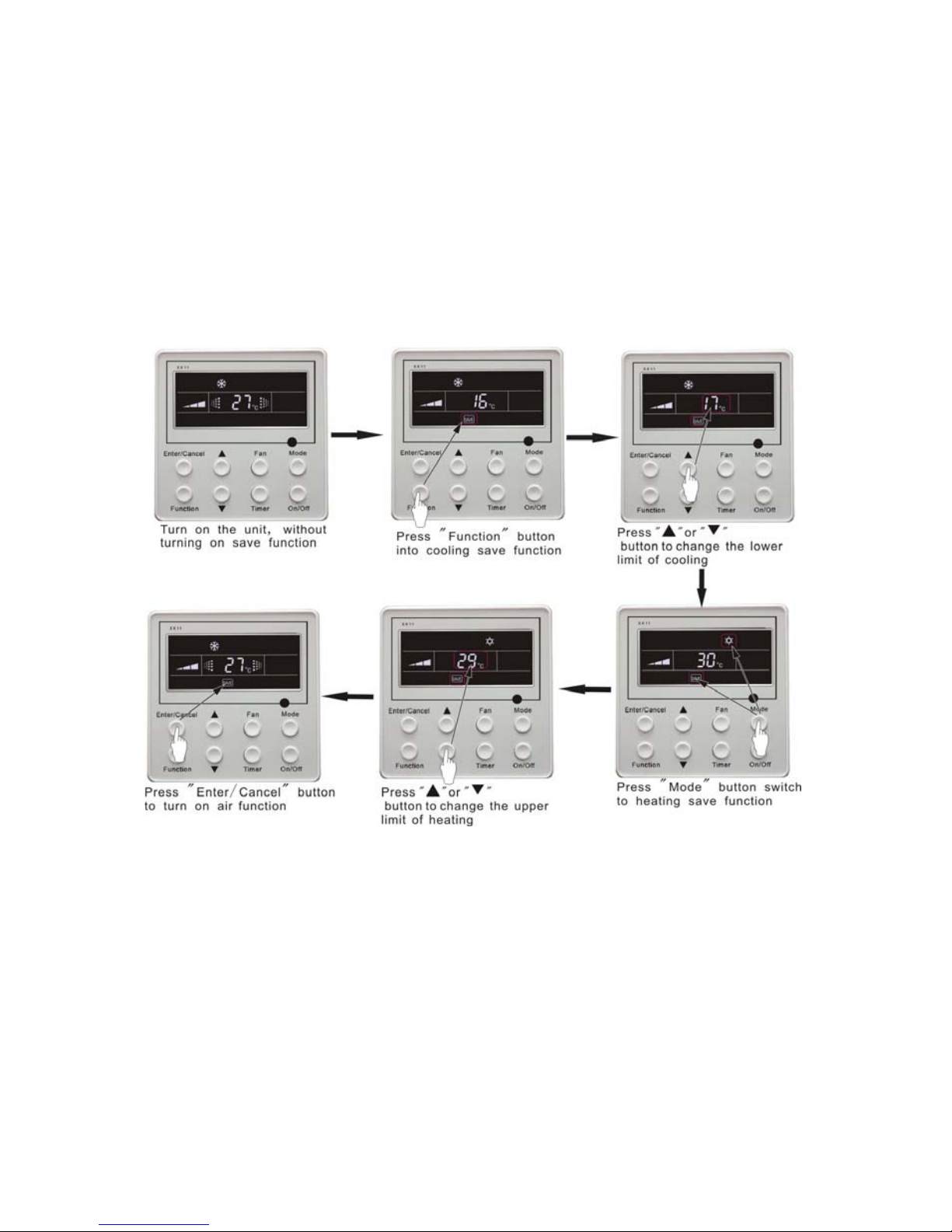
5.10 SAVE Function Setting
Energy Saving Function: Energy saving can make the air conditioner runs in a smaller temperature
range by setting lower limited value of setting temperature in cooling or dry mode and upper limited
value in heating mode.
14
Energy Saving Setting for Cooling
Under on-state and in cooling or dry mode of the unit, press Function button into energy saving
function, with SAVE blinking .Press ▲ or ▼ button to adjust lower limited value of setting temperature
in cooing mode. After that press Enter/Cancel button to turn on energy saving function for cooling.
Energy Saving Setting for Heating
Under on state and in heating mode of the unit, press Function button into energy saving function,
with SAVE blinking. Press Mode button into energy saving function for heating and then press▲ or ▼
button to adjust upper limited value of setting temperature in heating mode. After that, press
Enter/Cancel button to turn on energy saving function for heating.
After energy saving function is turned on, press Function button into energy saving function and
press Enter/cancel to cancel this function.
The energy saving setting is shown in the Fig.15:
Fig.15 Energy Saving Setting
Note:
1. In Auto running mode with save function on, the unit will be forcibly quit Auto running Mode and
change to current operation mode, After setting of save, sleep function will be canceled.
2. In save mode, if Function button is pressed or there is not any operation within 5s after the last
button operation, the system will be quit from save function setting and current data won’t be
memorized.
3. After power failure and then recovery, save function setting will be memorized.
4. The lower limited value in cooling mode is 16°C and the upper limited value in heating mode is
30°C.
5. After save setting, if the setting temperature is out of the range in the mode, the limited value will
prevail.

15
5.11 E-HEATER Setting*
E-HEATER: In the heating mode, E-heater is allowed to be turned on for improvement of
efficiency. If heating mode is turned on by button operation, auxiliary electric heating function will be
automatically turned on.
Press Function button in heating mode to go to the auxiliary electric heating function, the
E-HEATER blinking, and press Enter/cancel button to turn on this function. In this case, the
E-HEATER will be displayed, which means E-heater is allowed to be turned on.
If auxiliary electric heating function is on, press Function button to confirm or press Enter/cancel
button to cancel. In this case, E-HEATER won’t be displayed, which means E-heater is prohibited to be
turned on.
The setting of this function is shown as Fig.16 below:
Fig.16 Auxiliary Electric Heating Function Setting
Note:
E-HEATER can not be set in cooling, dry and fan mode, E-HEATER mark won’t be displayed.
The setting is shown in Fig.16

16
5.12 Blow Function Setting
BLOW function: After the unit is turned off, water in evaporator of indoor unit will be
automatically evaporated to avoid mildew.
In cooling and dry mode, press Function button till the unit enters BLOW function, with BLOW
blinking, and then press Enter/cancel button to turn on this function.
In BLOW mode, press Function button till the unit enters BLOW function and then press
Enter/cancel button to cancel this function.
BLOW function setting is shown in Fig.17:
Fig.17 Blow function setting
Note:
1. After setting BLOW function, turn off the unit by pressing On/Off button on remote controller,
indoor fan will run at low fan speed for 10 min. (BLOW shows).Meanwhile, if BLOW function is
canceled indoor fan will be turned off directly.
2. There is not BLOW function in fan or heating mode.

17
5.13 Quiet Function Setting
Quiet function consists of two kinds: QUIET and AUTO QUIET.
Press Function button till the unit enters quiet function setting state, Quiet or Auto Quiet mark
blinks. In this case, press▲ or ▼ button to switch between Quiet and Auto Quiet and then press
Enter/cancel button to turn on this function.
In quiet mode, press Function button till the unit enters quiet function. In this case, Quiet or Auto
Quiet icon blinks and then press Enter/cancel button to cancel this function.
Quiet function setting is shown in Fig.18:
Fig.18 Quiet function setting
Note:
3. During quiet function, fan speed is un-adjustable.
4. When turning on auto quiet function, the unit will enter quiet running state according to
temperature difference between room temperature and setting temperature. In this case, fan speed is
adjustable. If temperature difference between room temperature and setting temperature ≥ 4°C, fan
will keep its current speed; if 2°C≤temperature difference ≤3 ; fan speed will be ℃ reduced by one
grade ,but if it is at minimun. grade, it is un-adjustable.; if temperature difference ≤1°C, fan speed
will be at minimun grade
5. In auto quiet mode, fan speed can not be raised but reduced. If high fan speed is manually adjusted,
auto quiet mode will quit.
6. There is not auto quiet function in fan or dry mode. Quiet off is default after power failure and then
power recovery.
7. If quite function is set, turbo function will be canceled.

18
5.14 Field Functions
Under off-state of the unit, press Function and Timer buttons continuously for 5s to go to the
debugging menu. Press Mode button to adjust the setting items and ▲ or ▼ button to set the actual
value.
5.14.1 Ambient Temperature Sensor Setting
In field setting mode, press Mode button to adjust the temperature displayed location displaying 00,
and press ▲ or ▼ button to adjust setting state at timer displayed location. There are 3 types for
selection:
⑴ Indoor ambient temperature is that at return air inlet (01 is displayed at timer displayed location)
⑵ Indoor ambient temperature is that at the place of screen (02 is displayed at timer displayed location)
⑶ Return air inlet temperature sensor shall be selected for cooling, dry and fan modes and wired
controller temperature sensor (03 is displayed at timer displayed location) shall be selected for heating
and auto modes.
5.14.2 Three Grades of Speed for Indoor Fan
In field setting mode, press Mode button to adjust the temperature displayed location displaying 01
and press ▲ or ▼ button to adjust setting state at timer displayed location. There are 2 types for
selection:
⑴ 3 low grades (LCD displays 01)
⑵ 3 high grades (LCD displays 02)
Three low grades indicate high, medium and low grades and 3 high grades indicate super-high,
high and medium grades.
Press Enter/Cancel button to save the setting and quit after setting. If there is not any operation
within 20s after the system responds to the last button operation in this interface, the system will quit
this menu and display normal off-state; meanwhile, current setting won’t be saved.
5.15 Other Functions
5.15.1 Lock Function
Upon startup of the unit without malfunction or under off-state of the unit, press ▲ and ▼buttons
at the same time for 5s till the wired controller enters lock state. In this case, LCD displays:. After
that, repress these two buttons at the same time for 5s to quit lock state.
Under lock state, any other buttons won’t give any response to the press.
5.15.2 Memory Function
Memory switchover: Under off-state of the unit, press Mode and ▲ buttons at the same time for
5s to switch memory modes. During setting memory mode, Memory will be displayed. If this function
is not set, the unit will be under off state after power failure and then power recovery.
Memory recovery: If memory mode has been set for wired controller, the wired controller after
power failure will resume its original running state upon power recovery.
Note:
It will take about 5 seconds to save all the information, therefore, please do not cut down the power
at this time, or it may fails.

19
5.15.3 Enquiry of Outdoor Ambient Temperature
Under on or off state of the unit, press Enter/Cancel button for 5s, outdoor ambient temperature
will be displayed at temperature displaying location after a sound of click. This enquiry state will quit
by pressing any button. If there is not any operation for 20s, it will automatically quit.
Note:
1. This function will be shielded after energized of 12hr for some models of the units without
outdoor ambient sensors. Please refer to Instruction for details.
2. If malfunction of outdoor ambient sensor occurs, this function will be shielded in 12hr.
5.15.4 Selection of Centigrade and Fahrenheit
Under off state of the unit, press Mode and ▼ at the same time for 5s, the displayer panel will switch
between Centigrade and Fahrenheit.
5.15.5 Master/Slave Wired Controller Setting
Under the off status of the unit, press “Enter/cancel” and “Mode” at the same time for 5 seconds to
go to the master/slave wired controller setting interface, and then press ▲ or ▼ to make the adjustment.
In this case, only in the temperature display is there numbers displayed, 01 for the master wired
controller and 02 for the slave wired controller.
After that, press “Enter/cancel” to save the setting and quit this interface. If there is not any
operation in 20 seconds on this interface after the last button press, the system will quit automatically to
the normal off status without saving the current setting.
Note:
If there is only one wired controller, it only can be set as the master; otherwise the unit won’t run
normally

20
6. Error Display
If there is malfunction during running of the system, the wired controller will display error code at
temperature–displayed location. Once there is more than one malfunction, error codes will be displayed
circularly. If there are multiple circuit systems, the system number of failed system will be displayed
before the colon (not for single system).
If malfunction o·occurs, turn off the unit and contact nearest dealer for help.
As shown in Fig.19, it means high pressure protection of system 2 under unit on.
Fig.19
Error code meaning:
Error code Malfunction
E1 High pressure protection of compressor
E2 Indoor anti-freezing protection
E3 Low pressure protection of compressor
E4 High discharge temperature protection of compressor
E5 Compressor overload protection
E6 Communication malfunction
E9 Water overflow protection
F0 Indoor unit ambient sensor malfunction at air return opening
F1 Evaporator sensor malfunction
F2 Condenser sensor malfunction
F3 Outdoor unit ambient temperature sensor malfunction
F4 Discharge temperature sensor malfunction
F5 Ambient sensor malfunction on Displayer (or LED board)

21
The LED Indicator Display on the Main Board of Outdoor Unit (09K/12K)
This table is applicable to the electric control box of the 09K and 12K C Series DC inverter air
conditioners. Some of the items are not malfunction; they mean the normal running status
Running Status
Outdoor unit
Yellow Lamp
Outdoor unit
Red Lamp
Outdoor unit
Green Lamp
wired
controller
Display
Compressor started Flash once
Defrosting Flash twice Displayed
Anti-freezing protection Flash 3 times E2
IPM protection Flash 4 times E5
Over-current protection Flash 5 times E5
Heat exchanger overload protection Flash 6 times /
Discharge protection Flash 7 times E4
Compressor overload protection Flash 8 times E5
Power protection Flash 9 times E5
Module overheating protection Flash 10 times E5
EEPROM reading error Flash 11 times E5
Low voltage protection Flash 12 times E5
High voltage protection Flash 13 times E5
PFC over-current protection Flash 14 times E5
Unmatched indoor and outdoor
units
Flash 16 times /
Limited frequency(current) Flash once /
Limited frequency (discharge) Flash twice /
Limited frequency (overload) Flash 3 times /
Reduced frequency (anti-freezing) Flash 4 times /
Outdoor ambient temperature
sensor error
Flash 6 times F3
Outdoor pipe temperature sensor
error
Flash 5 times F2
Outdoor discharge temperature
sensor error
Flash 7 times F4
Up to the startup temperature Flash 8 times /
Limited frequency
(module temperature)
Flash 11 times /
Limited frequency (power)
Flash 13
times
/
Communication normal
Flash
continuously
/
Communication error Black out E6
Indoor ambient temperature sensor
error
F0
Indoor pipe temperature sensor
error
F1

22
Definition of Malfunction Codes of DC Inverter General Outdoor Unit (V1.6)
This table is applicable to the electric control box of the other models of C-Series DC inverter air
conditioners.
Malfunction Item
Outdoor unit display of
dual 8 numeral tube
wired controller
Display
DC busbar over voltage protection PH E5
Overheat protection of radiator P8 E5
Current sensor malfunction Pc E5
Carbon fin sensor malfunction P7 E5
Compressor current protection P5 E5
Low voltage protection PL E5
Compressor startup failure Lc E5
PFC abnormality Hc E5
Compressor clogged LE E5
Drive resetting P0 E5
The compressor motor in loss of synchronization H7 E5
Missing phase, Speed discard Ld E5
Malfunction from driving part to main-control
communication
P6 E5
IPM module protection H5 E5
Compressor over speed LF E5
Sensor connection protection Pd E5
Temperature drift protection PE E5
AC contactor protection P9 E5
High-pressure protection E1 E1
Low-pressure protection E3 E3
Exhaust protection E4 E4
Compressor overload protection H3 E5
Communication malfunction (among indoor unit,
outdoor unit and wired controller)
E6 E6
Outdoor ambient temperature sensor malfunction F3 F3
Coil pipe intermediate temperature sensor
malfunction of outdoor unit
F2 F2
Exhaust temperature sensor malfunction F4 F4
Defrosting (non-malfunction) 08 defrost
Oil return (non-malfunction) 09 no display
Mismatch of indoor unit model LP no display
AC current protection (input side) PA E5
Driver board environment temperature sensor
malfunction
PF E5
AC input voltage abnormality * PP E5
Electrification loop malfunction * PU E5

23
7. Remote control operation procedure(standard fitting)
Name and Function-Remote Control
Note:
Be sure that there are no obstructions between receiver and remote controller.
Don’ t drop or throw the remote controller .
Don’ t let any liquid in the remote controller and put the remote controller directly under the
sunlight or any place where is very hot.
Fig.20

24
Name and Function-Remote Control. (Remove the cover)
Note:
This type of remote controller is a kind of new current controller. Some buttons of the controller
which are not available to this air conditioner will not be described below.
Operate on unmentioned buttons would not impact on the normal use.
Fig.21

25
COOL mode operation procedure
According to difference between room temp and set temp, microcomputer can control cooling on
or not.
If room temp is higher than set temp., compressor runs at COOL mode.
If room temp is lower than set temp., compressor stops and only indoor fan motor runs.
Set TEMP should be in range of 16℃ to 30℃.
Fig.22

26
HEAT mode operation procedure
If room temp is lower than set temp, compressor runs at HE AT mode;
If room temp is higher than set temp, compressor and outdoor fan motor stop, only indoor fan
motor runs.
Set TEMP should be in range of 16℃to 30℃
Fig.23

27
DRY mode operation procedure
If room Temp is more than 2℃ below Set TEMP. , compressor and outdoor unit fan motor stop,
indoor unit fan motor runs at low speed.
If room Temp is between 2℃ of Set TEMP, the compressor and outdoor unit fan motor will run for
6 minutes and stop for 4 minutes, and always in such a cycle, the indoor unit fan motor will run at low
speed.
If room Temp is more than 2℃ above Set TEMP. , compressor and outdoor unit fan motor run as
COOL mode , the indoor unit fan motor runs at low speed.
Fig.24

28
AUTO mode operation procedure
According to room temp, microcomputer can automatically set COOL.HEAT.DRY operation mode,
so as far best effect.
At AUTO mode operation, standard TEMP is 26℃ for COOL mode, 24℃ for DRY mode and 20℃
for HEAT mode.
Fig.25

29
FAN mode operation procedure
Connect the unit to power supply.
Press the “ON/OFF” key.
Press the mode key to select the “FAN” mode. The unit shall operate under “FAN” mode.
Press the “FAN” key to select from high, medium and low speed.
Fig.26

30
TIMER operation procedure
Fig.27

31
SLEEP mode operation procedure
When the unit is cooling or drying, if SLEEP operation is set, TEMP. would increase 1℃ in 1 hour
and 2℃ in 2 hours. Indoor fan motor runs at low speed.
When the unit is heating, if SLEEP operation is set, TEMP would decrease 1℃ in 1 hour and 2℃
in 2 hours. Indoor fan motor runs at low speed.
Fig.28

32
How to insert batteries
Fig.29

33
8. Part Names and Their Functions
CAUTION:
Wrong wiring connection will cause electrical malfunction.
Do not pull the wire when fixing it with wire
Notes:
1. If the supply cord is damaged, it must be replaced by the manufacturer or its service agent or a
similarly qualified person in order to avoid a hazard.
2. The appliance will be installed in accordance with national wiring regulations.
States of the Indicating Lamps:
1. Indicating Lamp of “POWER”: The
indicating lamp will shine when power on,
while it will go out when power off.
2. Indicating Lamp of “COOL” :
3. The indicating lamp will shine when
“COOL” is activated, while it will go out
when “COOL” is deactivated.
4. Indicating Lamp of “HEAT”: The indicating
lamp will shine when “HEAT” is activated,
while it will go out when “HEAT” is
deactivated.
5. Indicating Lamp of “TIMER”:
6. The indicating lamp will shine when
“TIMER” is activated, while it will go out
when “TIMER” is deactivated or the set
①
②
③
④
Communication cable
Remote controller
Refrigerant tube
Drain pipe
Fig.30

34
Fig.31
Fig.32
9. Maintenance
Before inspection and maintenance of the unit, please shut down the unit and set the power switch
to “OFF” to cut off the power supply.
Cleaning the Air Filter
Remove the air filter; clean it by a vacuum cleaner or if is very dirty, wash it with soap water and then
wipe off until it is completely dry before reinstallation.
Suggestion
If the air filter is dry, it will cause the reduction of
airflow, and the unit will be easily overloaded and
consumes 6% more energy. So regular cleaning
is necessary.
Cleaning the Unit
Clean the air conditioner and the remote controller
with dry cloth or a vacuum cleaner. If damp cloth is
used, remove moisture by using dry cloth afterward.
CAUTION
1. Do not use benzene gasoline, thinners or
2. polishing products for cleaning.
3. Do not wash with hot water (above 40 ), ℃
4. Otherwise some parts of the unit may be deformed.
Before the Seasonal Use
1. Ensure that nothing blocks the air inlet and outlet of the indoor and outdoor unit.
2. Running the unit without air filters can cause malfunctions due to dirt or dust. Thus, the air filter
should be installed at all times.
3. Ensure that drainage hose is not bent or clogged.
4. Check if the unit is properly installed.
After the Seasonal Use
1. Switch off the main switch of the power supply
2. Clean the air filters and other parts (by professionals)
3. Leave the fan running along for another 2-3 hours to dry the inside of the unit.
CAUTION:
Wrong wiring connection will cause electrical malfunction.
Do not pull the wire when fixing it with wire
Fig31

35
Fig.33
10. Operating Guide
The cleaning and replacement of the filter is only permitted to be done by the professionals. Before
open the grille to clean the filter, please cut off the power supply and wait unit the fan motor stops.
1. The temperature should not be set lower than what you need, otherwise it would result in increased
energy cost.
2. To distribute cool air throughout the room, adjust the air flow direction as shown by the arrows (see
the picture).
3. Clean the air filter every week for higher efficiency.
4. Close the window and door while operating the unit to prevent leakage of cooled air to save energy.
5. Draw close the curtains or close glass windows when cooling to prevent heat load from sun light
which may cause more electricity cost.
6. In case of ineffective ventilation, open the window to ventilate the room air once in a while but not
too long since cooled air will be uselessly drained out.
Fig34
Fig35

36
11. Precautions
1. Turn off the air conditioner if it is not needed, as electricity interference may occurs while it is
running .If the unit is not to be used for a long time, cut off the power supply main switch.
Fig.36
2. Do not insert objects into the air inlet or outlet when the air conditioner is running as it may cause
damage or personal injury .Also pay special attention when children are around.
3. Do not locate any obstacle against the air flow direction of indoor and outdoor unit .Inefficient
performance or malfunction may result.
Fig.37
4. Do not channel the air flow directly at people, especially infants, aged persons, or patients.
5. Do not locate a heater or any other heat source close to the unit. The heat may deform plastic parts.
Fig.38

37
12. Checking Before Contact the Service Man
Check the followings before contact the service man. You may find the solution to your problems.
After checking, if it still does not operate, please contact your local dealer.
Table.3
Problem Solution(s)
The unit does not run
z check if the power supply is in order
z check if the timer switch is on or not
The air conditioner runs but does not cool
enough
z check if the preset temperature is too high
z check if the sunlight shines directly into
the room
z check if the door and window are opened
z check if there is anything blocking the air
discharge
z check if the exhaust fan still operates
z check if the air filter is dirty or clogged
Vapor or mist fume comes out from the
unit when it runs
z check if the hot air in the room is mixed
with cool air, which may cause smog.
The remote controller works abnormally
z check if the batteries are inserted in correct
directions
z check if the batteries are exhausted
12.1 Accessories List for Installation
Table.4
Accessories List for Installation (Outdoor Unit)
Numbe
r
Name Shape Quantity Type Remark
1
Drainage Hole
Cap
for Outdoor
Unit
1(3)
1 for 09K\12K
3for18\24\30\36\42\48\
60K
2
Drainage Joint
for Outdoor
Unit
1
Only for heat pump
units
Notes: See the packing list to check the delivered accessories.
The accessory with * indicates it is not included but should be prepared by the clients themselves.

38
Table.5
Accessories List for Installation (Indoor Unit)
Number Name Shape Quantity Type Remark
1
Nut (with
gasket)
8 M10
2 Tie Line
4 200mm
3
Installation
Paperboard
1
used for
ceiling
drilling
4
Thermal
Insulation Layer
of Discharge
Pipe
1
5
Thermal
Insulation Layer
of Inlet Liquid
Pipe
1
6 Sealing Plaster*
2
7
Remote
Controller
1
8 Battery
2
9 Power Cord *
1
(H05VV-F
)3×1.5mm
2
10
Communication
Cable*
1 AWG#24
11 Drain Hose*
1 Φ17×1.75
12 Pipe Clamp*
1
13 Operation
1
Notes: See the packing list to check the delivered accessories.
The accessory with * indicates it is not included but should be prepared by the clients
themselves.

39
Fig.39
12.2 Installation of the Indoor Unit
When install the indoor unit, you can use a paper pattern for reference and make sure that the
drainage side be 10mm lower than the other side in order to drain the condensation water fluently.
Table.6
Model A B C D E
1220 225 1158 700 280
1420
245
1354
700
280
1700
245
1634
700
280
V1KI-09
V1KI-12
V1KI-18
V1KI-24
V1KI-30
V1KI-36
V1KI-45
V1KI-50
V1KI-60

40
Fig.40
Cautions for Installation Where Air Conditioner Trouble is Likely to Occur
1. Where there is too much of oil.
2. Where it is acid base area.
3. Where there is irregular electrical supply.
Selection of Installation Location
1. Such a place where cool air can be distributed throughout the room.
2. Such a place where condensation water is easily drained out.
3. Such a place that can handle the weight of indoor unit.
4. Such a place which has easy access for maintenance.
5. Such a place where is easy to connect the outdoor unit.
6. Such a place which is 1m or more away from other electric appliances such as television, audio
device, etc.
7. Avoid a location where there is heat source, high humidity or inflammable gas.
8. Do not use the unit in the immediate surroundings of a laundry, a bath, a shower or a swimming
pool.
9. Ensure that the installation conforms to the installation dimension diagram.
10. A space around the unit is adequate for ventilation (See Fig.41)
Fig.41
Insulation
Paper plank

41
There are two types of installation:
Ceiling T ype and Floor Type
Each type is similar to the other as follows:
Determine the mounting position on ceiling or wall by using the paper pattern to indicate the
indoor frame. Mark the pattern and pull out the paper pattern. Remove the return grill, the side panel
and the hanger bracket from the indoor unit as per procedures below.
1. Press the fixing knob of the return grilles and Loosen fixing bolts (M4.2). It will be opened widely,
and then pull it out from the indoor unit.(See Fig.41)
2. Remove the side panel fixing screws and remove it away by pulling it out at the front direction
(arrow direction). (See Fig.42)
3. Loosen two hanger bracket setting bolts (M10) on earth side for less than 10mm. Remove two
hanger bracket fixing bolts (M6) on the rear side. Detach the hanger bracket by pulling it backward
(See Fig.44)
Fig.42
Set the suspension bolt. (Use M10 size suspension bolts)
Adjust the distance between the unit and the ceiling slab beforehand (See Fig.43). Fix the hanger
bracket to the suspension bolt.
WARNING!
1. Make sure that extended suspension bolt from the ceiling stays inside the arrowed position.
Readjust the hanger bracket when it is outside the arrowed position. (See Fig.45)
2. Suspension bolt stays inside the cap of the indoor unit .Never remove the cap. Lift the unit and
slide the hanger bracket in the way that the holes on it will match with the corresponding bolts.
(See Fig.46)
3. Screw tightly both hanger brackets setting bolts (M10.) (See Fig.44)
4. Screw tightly both hanger bracket fixing bolts (M6) to prevent the movement of the indoor unit.
(See Fig.44)
Adjust the height of the unit to incline slightly the rear side of the drain pipe so as to optimize the
drainage.
CAUTION!
Adjust the height by turning the unit with a spanner. Insert the spanner from the hanger bracket
opening. (See Fig.48)
Side panel fixing screw (M4.2)

42
Hanging and Mounting
It is possible to carry out the installation by using inward facing hanger brackets without moving
the brackets from the indoor unit. (See Fig.47)
Be sure to use only the specified accessories and parts for installation.
35mm or less
Hanger bracket
Suspension bol
Fig.43 Fig.46
Fig.44 Fig.47
Fig.45 Fig.48
12.3 Installation of the Outdoor Unit
12.3.1 Installation Location of the Outdoor Unit
1. The foundation must be solid enough to bear the weight and vibration of the unit.
2. The space around the unit is adequate for ventilation.
3. The location is not close to any inflammable gases.
4. The location is sufficiently isolated so that the running noise and the hot exhaust air do not disturb
the users or their neighbors.
5. There is an easy access to check and maintenance.
6. Ensure the spaces indicated by arrows to the wall, ceiling, fence, or other obstacles.

43
Fig.49
CAUTION
Installation in the following places may cause problems
If it is unavoidable to select such places, consult with your distributor or dealer.
1. A place with machine oil
2. A saline place such as a place very close to seashore
3. A place with corrosive gas
4. A place where high-frequency waves are generated by the radio equipment, welder or medical
equipment.
12.3.2 Electric Wiring Connection
Fig.50 Fig.51
CAUTION!
1. Wrong wiring may cause fire or
electric shock.
2. Do not pull the wire when fixing it
3. With wire clamps and clasps.
4. Do not let the wire too loose
5. All the electrical work must be
done by qualified personnel
according to the local rules and this
instruction
6. The rated voltage and the exclusive
Fig.52
U1RS-09
U1RS-12
U1RS-18 U1RS-24
U1RS-45
U1RS-48
U1RS-30
U1RS-36
U1RT-36
U1RT-45
U1RT-50
U1RT-60

44
circuit must be used.
7. Leakage circuit-breaker must be installed.
8. Please use the specified fuse.
9. If the power supply cord of the unit is damaged it must be replaced by the manufacturer or its
service agent or a similarly qualified person in order to avoid a hazard.
10. An all-pole disconnection air switches which have a contact separation of at least 3mm in all poles
is needed
12.3.3 Profile Dimensions of the Outdoor Unit
Fig.53
Table.7
Item
A B C D E
776
320
540
510
286
955 396 700 560 360
980 427 790 610 395
1107
440
1100
631
400
1085
427
1365
620
395
12.3.4 Unit Installation Instructions
Precautions on Installation of the Outdoor Unit
To ensure the unit in proper function, the installation location must be selected in accordance with
following principles:
1. Outdoor unit should be installed in the way that the air discharged by out door unit will not return
and that sufficient space for repair will be provided around the machine.
2. The installation site must have good ventilation, so that the outdoor unit can take in and exhaust
Model
U1RS-09
U1RS-12
U1RS-18
U1RS-24
U1RS-45
U1RS-48
U1RS-30
U1RS-36
U1RT-36
U1RT-45
U1RT-50
U1RT-60

45
enough air. Ensure that there is no obstacle to the air intake and exhaust of the outdoor unit. If
there is any obstacle blocking the air intake or exhaust, remove it.
3. Place of installation should be strong enough to support the weight of outdoor unit, and it should
be able to insulate noise and prevent vibration. Ensure that the wind and noise from the unit will
not affect your neighbors.
4. Avoid direct sunshine over the unit. It is better to set up a sun shield as a protection.
5. Place of installation must be able to drain the rainwater and defrosting water.
6. Place of installation must ensure the machine will not be buried under snow or subject to the
influence of rubbish or oil fog.
7. The installation site must be at a place where the air exhaust outlet does not face strong wind.
12.4 Schematic Diagram of Unit Line Connection
Electric wiring connection
The section area of cables selected by users must not be smaller than the specifications shown in
the following diagram. The signal wire between indoor and outdoor unit will be installed in the shielded
bushing.
Fig.54
1.Power cord 3×2.5 mm2(H07RN-F) 2.Power cord 3×1.0 mm2(H05VV-F)
3.Communication Cords
1.Power cord 3×4 mm2(H07RN-F) 2.Power cord 3×1.0 mm2(H05VV-F)
3.Communication Cords
1.Power cord 3×4 mm2(H07RN-F) 2.Power cord 3×1.5 mm2(H05VV-F)
3.Communication Cords
1.Power cord 3×6 mm2(H07RN-F) 2.Power cord 3×1.5 mm2(H05VV-F)
3.Communication Cords
U1RS-09
U1RS-12
U1RS-18
U1RS-24
U1RS-45
U1RS-48
U1RS-30
U1RS-36
+
+
+
+
+
+
+
+
V1KI-09
V1KI-12
V1KI-18
V1KI-24
V1KI-30
V1KI-36
V1KI-45
V1KI-50
U1RS-09
+
V1KI-09
U1RS-12
+
V1KI-12
U1RS-18
+
V1KI-18
U1RS-24
+
V1KI-24
U1RS-45
U1RS-30
+
+
V1KI-30
V1KI-45
U1RS-36
+
V1KI-36
U1RS-48
+
V1KI-50

46
Fig.55
1.Power cord 5×4 mm2(H07RN-F) 2.Power cord 3×1.5 mm2(H05VV-F)
3.Communication Cords
The following table recommended by the model selection manual is about how to select the air
switch and power cable.
Warning! :
The section area of cables selected by users must not be smaller than the specifications shown in
the table below
Table.8
Model Power Supply
Capability of Air
Switch(A)
(Outdoor/Indoor)
Minimum Sectional Area
Of Earth Wire (mm2)
(Outdoor/Indoor)
16/6 2.5/1.0
16/6 2.5/1.0
20/6 4/1.0
20/10 4/1.5
32/10 6.0/1.5
32/10 6.0/1.5
32/10 6.0/1.5
220-240V~
50HZ
32/10 6.0/1.5
380-415V 3N~
50Hz
20/10 4/1.5
Note: The parameters of the power cord listed above are only applicable to the BV single-core power
cord which is laid within the plastic bushing and used at 40℃, and those of the air switch are applicable
to the one which also is used at 40℃. If the actual installation conditions changes, please refer to the
instructions of the power cord and the air switch.
U1RT-36
U1RT-45
U1RT-50
U1RT-60
+
+
+
+
V1KI-60
V1KI-36
V1KI-45
V1KI-50
U1RT-36
+
V1KI-36
U1RT-50
+
V1KI-50
U1RT-45
+
V1KI-45
U1RT-60
+
V1KI-60
U1RS-09
U1RS-12
U1RS-18
U1RS-24
U1RS-45
U1RS-48
U1RS-30
U1RS-36
20/10 4/1.5
20/10 4/1.5
20/10 4/1.5
U1RT-36
U1RT-45
U1RT-50
U1RT-60

47
Rated Parameters and Outline Dimensions of the Fuse
Table.9
Unit Code
Rated
parameter
Dimensions
46010408/
46010029
250V/15A
250V/3.15A
46010014/
46010023
250V/3.15A、
250V/30A
46010014/
46010023
250V/3.15A、
250V/30A
46010014/
46010023
250V/3.15A、
250V/30A
46010014/
46010023
250V/3.15A、
250V/30A
46010014/
46010023
250V/3.15A、
250V/30A
46010013 250V/5A
All the indoor units 46010013 250V/5A
U1RS-09
U1RS-12
U1RS-18
U1RS-24
U1RS-45
U1RS-48
U1RS-30
U1RS-36
46010014 250V/3.15A
U1RT-36
U1RT-45
U1RT-50
U1RT-60
46010014 250V/3.15A
46010014 250V/3.15A
46010013 250V/5A

48
12.5 Connecting Pipe Preparation
12.51 Pipe Preparation
Pipe & Electrical Wire Cutting
1. Use cutting tools easily found in the market.
2. Measure precisely both outer & inter pipes.
3. The length of the pipe should be a little longer
than the actual measured value.
4. The wire should be 1.5m longer than the
refrigerant tube
Reaming
1. Clean the inside of the inner refrigerant tube.
2. While reaming, the tube end must be on the top of
the reamer to prevent any dust going back into the
tube.
Flaring the Pipe End
Flare both ends of the pipe with flaring kits by
fitting the flare nut on the pipe before flaring. Set the die
on the pipe in the way that the pipe end is 0.5mm above
the top of the die. Then, check if the pipe end is even and
perfectly round or not.
Wire Connecting and Taping
(See the figure on right)
Fig.56
Fig.57
Fig.58
Fig.59

49
12.5.2 Refrigerant Piping work
The refrigerant is R410A for" " series outdoor units,
GWP=2020 ODP=0
The standard pipe length is 5m. When the length (L) of the connecting pipe is less than or equals
7m, there is no need to add refrigerant. If the connecting pipe is longer than 5m, it is required to add
refrigerant. In the below table, the amounts of refrigerant to be added for different models are listed for
each additional meter of pipe length.
Select copper pipes for gas and liquid as informed in specific table (see the pipe table below).For
dust and moisture protection, before assembly of the pipe and its insulation, both ends of the pipe must
be covered.
Table.10
Size of Fitting Pipe
(Inch)
Item
Model
Gas
Pipe
Liquid
Pipe
Max Pipe
Length
(m)
Max Height
Difference
between
Indoor Unit
and Outdoor
Unit(m)
Amount of
Additional
Refrigerant
to Be
Filled For
Extra(Length
of Pipe)
Drainage
Pipe
(Diameter
× Wall
Thickness
)
15 30
15 30
15 30
15 60
15 60
15 60
30 60
30 60
30 60
Φ17×1.75
Avoid pipe bending as mush as possible, if it is necessary, the bending radius must be more than 3
or 4 cm.
Connection between an Indoor unit and an Outdoor Unit
1. Unscrew the flare nut for releasing pressure gas in the indoor unit. If there is no high pressure gas
blowing out, it is the signal of leakage for the indoor unit.
2. Fit the flare nut to the liquid pipe. Flare the pipe’s end with flare tools.
Tighten both flare nuts into gas pipe and liquid pipe at the indoor unit with two spanners.
Liquid pipe
Fig.60
3/8 1/4 20
V1KI-09
V1KI-12
V1KI-18
V1KI-24
V1KI-30
V1KI-36
V1KI-45
V1KI-50
V1KI-60
3/8 1/4 20
1/2 1/4 20
5/8 3/8 30
5/8 3/8 30
5/8 3/8 30
5/8 3/8 50
5/8 3/8 50
3/4 3/8 50
U1RT-**

50
12.5.3 Air Purging
The purpose of the air purging is to get rid of moisture and air in the system, otherwise moisture
and air may cause ineffectiveness of the compressor which directly affects the cooling capacity.
Purging by Using Vacuum
After tightening the flared nuts between the indoor and the outdoor
units
1. Remove the blank cap of a three-way valve by using
a torque wrench, and then check if both high pressure
and low pressure valves are in closed condition or not.
2. Remove the nut at the service port.
3. Connect a gauge into the service port and a vacuum pump.
Remove the gauge and tighten up the nut at the service port.
4. Use a hexagonal wrench to open both high pressure and low pressure valves to the end (counter
clockwise).
5. Tighten the blank cap of the three-way valve.
Gap Leakage Check
1. Check if it leaks or not by applying soapsuds on every
joint and then inspect carefully. After the check, wipe
them off completely.
2. Cover the indoor unit joint with pipe insulation and
four plastic bands to prevent condensing at joints.
Fig.61
Fig.62

51
12.5.4 Liquid Pipe and Drain Pipe
If the outdoor unit is installed lower than the indoor unit
(See Fig.63)
1. A drain pipe should be above ground and the end of the
pipe does not dip into water. All pipes must be restrained
to the wall by saddles.
2. Taping pipes must be done from bottom to top.
3. All pipes are bound together by tape and restrained to
wall by saddles.
If the outdoor unit is installed higher than the indoor unit (See Fig. 64)
1. Taping should be done from lower to the upper part.
2. All pipes are bound and taped together and also should
be trapped to prevent water from returning to the room
(See Fig.64).
3. Restraint all pipes to the wall with saddles.
Fig.63
Fig.64

52
12.5.5 Drain Pipe
CAUTION:
make sure the drain flows out.
Drain pipe
1. The drain pipe outlet direction can be chosen from either the right rear or right.
2. The diameter of the drain pipe should be equal to or greater than the diameter of the connecting
pipe. (Vinyl tube: pipe size:20 mm, outer dimension: 26mm)
3. Keep the drain pipe as short as possible and incline downwards at a gradient of at least 1/100 to
prevent air pockets (See Fig.65)
4. Use the drain hose ④ and clamp ⑤. Insert the drain hose completely into the drain socket, and
tighten the clamp within the range of the gray tape unit the screw head is less than 4mm above the
hose (See Fig.66, 67)
5. Insulate the clamp and drain hose by wrapping the sealing pad over them.
6. No folding of the drain hose is allowed in the indoor unit. (See Fig.68)
Confirm that smooth drainage is achieved after the pipe working.
Inject 600cc water into the drain pan from the air outlet to see if the drainage goes well or not. (See
Fig.69)
Fig.65
Fig.68
Fig.67
Fig.66
Fig.69

53
12.5.6 Routine Checks after Installation
Check after installation
Table.11
Items to be checked Possible Malfunction(s) Items to be checked
Has it been fixed firmly?
The unit may drop, shake or emit
noise.
Has it been fixed firmly?
Have you done the
refrigerant leakage test?
It may cause insufficient
refrigerating capacity.
Have you done the
refrigerant leakage test?
Is the heat insulation
sufficient?
It may cause condensation and
dripping.
Is the heat insulation
sufficient?
Does the unit drain well?
It may cause condensation and
dipping.
Does the unit drain well?
Is the voltage in accordance
with the rated voltage
marked on the nameplate?
It may cause electric malfunction
or damage the part.
Is the voltage in accordance
with the rated voltage
marked on the nameplate?
Is the electric wiring and
piping connection installed
correctly and securely?
It may cause electric malfunction
or damage the part
Is the electric wiring and
piping connection installed
correctly and securely?
Has the unit been connected
to a secure earth
connection?
It may cause electric leakage.
Has the unit been connected
to a secure earth connection?
Is the power cord specified?
It may cause electric malfunction
or damage the part.
Is the power cord specified?
Have the inlet and outlet
been covered?
It may cause insufficient
refrigerating capacity.
Have the inlet and outlet
been covered?
Has the length of the
connection pipes and the
refrigerant charge been
recorded?
The refrigerating capacity may
be not accurate.
Has the length of the
connection pipes and the
refrigerant charge been
recorded?
WARNING! :
1. This appliance is not intended for use by persons (including children) with reduced physical
sensory or capabilities, or lack of experience and knowledge, unless they have been given
supervision or instruction concerning the use the appliance by a person responsible for their safety.
2. Children should be supervised to ensure that they do not play with this appliance.

54
12.5.7 Test Running
Evaluation of the Performance
1. Check the voltage of the main electrical wire.
2. Use a thermometer to measure both inlet and outlet cool air.
3. The difference between inlet air and outlet air
temperature should not be less than 8℃
4. The unit has the function of auto-restart and it
can remember the running mode before power
failure
5. Be sure to use the exclusive accessories listed
above in the installation instructions, or it may
result in water leakage, electric shock, fire, etc.
Fig.70

55
13. Appendix
Air Conditioner Normal Working Conditions and Working Rang:
Notes:
1. The design of this unit conforms to the requirements of EN14511 standard.
2. The air volume is measured at the 0Pa external static pressure.
3. Cooling (heating) capacity stated above is measured under nominal working conditions
corresponding to 0Pa external static pressure. The parameters are subject to change with the
improvement of products, in which case the values on the nameplate will prevail.
This product must not be disposed together with the
domestic waste but disposed at the authorized place for
the recycling of electric and electronic appliances.
Indoor Side Outdoor Side
Test Condition
DB(℃) WB(℃) DB(℃) WB(℃)
Nominal Cooling 27 19 35 24
Nominal Heating 20 — 7 6
Rated Cooling 32 23 43 26
Low Temp.
Cooling
21 15 18 —
Rated Heating 27 - 24 18
Low Temp.
Heating
20 — -7 -8

66129907237
 Loading...