


2
CONTENTS
PRODUCT ....................................................................................................................................... 2
1 MODELS LIST .................................................................................................................... 2
1.1 Outdoor Unit
............................................................................................................... 2
1.2 Indoor Unit
.................................................................................................................. 3
2 NOMENCLATURE ............................................................................................................. 4
3 FUNCTION .......................................................................................................................... 4
4 PRODUCT DATA ................................................................................................................ 5
4.1 Product Data at Rated Condition ................................................................................. 6
4.2 Operation Range
........................................................................................................ 19
4.3 Electrical Data ........................................................................................................... 20
5 PIPING DIAGRAM ........................................................................................................... 21
CONTROL .................................................................................................................................... 23
1 OPERATION FLOWCHART .......................................................................................... 23
1.1 Cooling/Dry Operation
.............................................................................................. 23
1.2 Heating Operation ..................................................................................................... 24
2 MAIN LOGIC .................................................................................................................... 25
2.1 Cooling ...................................................................................................................... 25
2.2 Dry Mode .................................................................................................................. 26
2.3 Heating Mode ............................................................................................................ 27
2.4 Defrosting .................................................................................................................. 28
2.5 Fan Mode .................................................................................................................. 29
3 WIRELESS REMOTE CONTROLLER ......................................................................... 30
3.1 Operation View ......................................................................................................... 30
3.2 Display V
iew ............................................................................................................. 32
4 WIRED REMOTE CONTROLLER ................................................................................ 33
4.1 Operation View ......................................................................................................... 33
4.2 Display V
iew ............................................................................................................. 35
4.3 Dimension ................................................................................................................. 36
4.4 Installa
tion ................................................................................................................. 36
5 CENTRALIZED CONTROLLER ................................................................................... 38
5.1 Centralized Controller-not with week timer .............................................................. 38
5.2 Centralized Controller-week timer ............................................................................ 39
5.3 Field Setting .............................................................................................................. 43
5.4 Control Wiring Design
.............................................................................................. 44
INSTALLATION ........................................................................................................................... 46
1 INDOOR UNIT INSTALLATION ................................................................................... 46
1.1 Installation of Duct
Type ........................................................................................... 46
1.2 Installation of Ceiling Type ....................................................................................... 55
1.3 Installation of Cassette Type ..................................................................................... 60
2 OUTDOOR UNIT INSTALLATION ............................................................................... 71
2.1 Before Installation ..................................................................................................... 71

3
2.2 Installation Site .......................................................................................................... 71
2.3 Caution for Installation ............................................................................................. 71
2.4 Dimension Data ......................................................................................................... 72
2.5 Installation Clearance Data ....................................................................................... 73
3 REFRIGERATION PIPING WORK ............................................................................... 74
3.1 Refrigeration Piping W
ork Procedures ...................................................................... 74
3.2 Caution in Conne
cting Pipes ..................................................................................... 77
3.3 Specification of C
onnection Pipe .............................................................................. 78
4 ELECTRIC WIRING WORK .......................................................................................... 79
4.1 Wiring Principle
........................................................................................................ 79
4.2 Electric Wiring Design
.............................................................................................. 83
4.3 Specification of Power Supply W
ire and Air Switch ................................................ 86
MAINTENANCE .......................................................................................................................... 89
1 TROUBLE TABLE ............................................................................................................ 89
2 FLOW CHART OF TROUBLESHOOTING .................................................................. 93
3 WIRING DIADRAM ....................................................................................................... 103
3.1 Wiring Diagram-Outdoor Units
.............................................................................. 103
3.2 Wiring Diagram-Indoor units .................................................................................. 111
4 DISASSEMBLY AND ASSEMBLY PROCEDURE OF MAIN PARTS_ .................... 113
4.1 Outdoor Unit
........................................................................................................... 113
4.2 Indoor Unit
.............................................................................................................. 141
5 EXPLODED VIEWS AND PART LIST ........................................................................ 160
5.1 Outdoor Unit
........................................................................................................... 160
5.2 Indoor Unit
.............................................................................................................. 176

INVENTOR COMMERCIAL AIR CONDITION U-MATCH AIR
CONDITIONERS
1
PRODUCT
U-MATCH AIR CONDITIONERS PRODUCT
2
PRODUCT
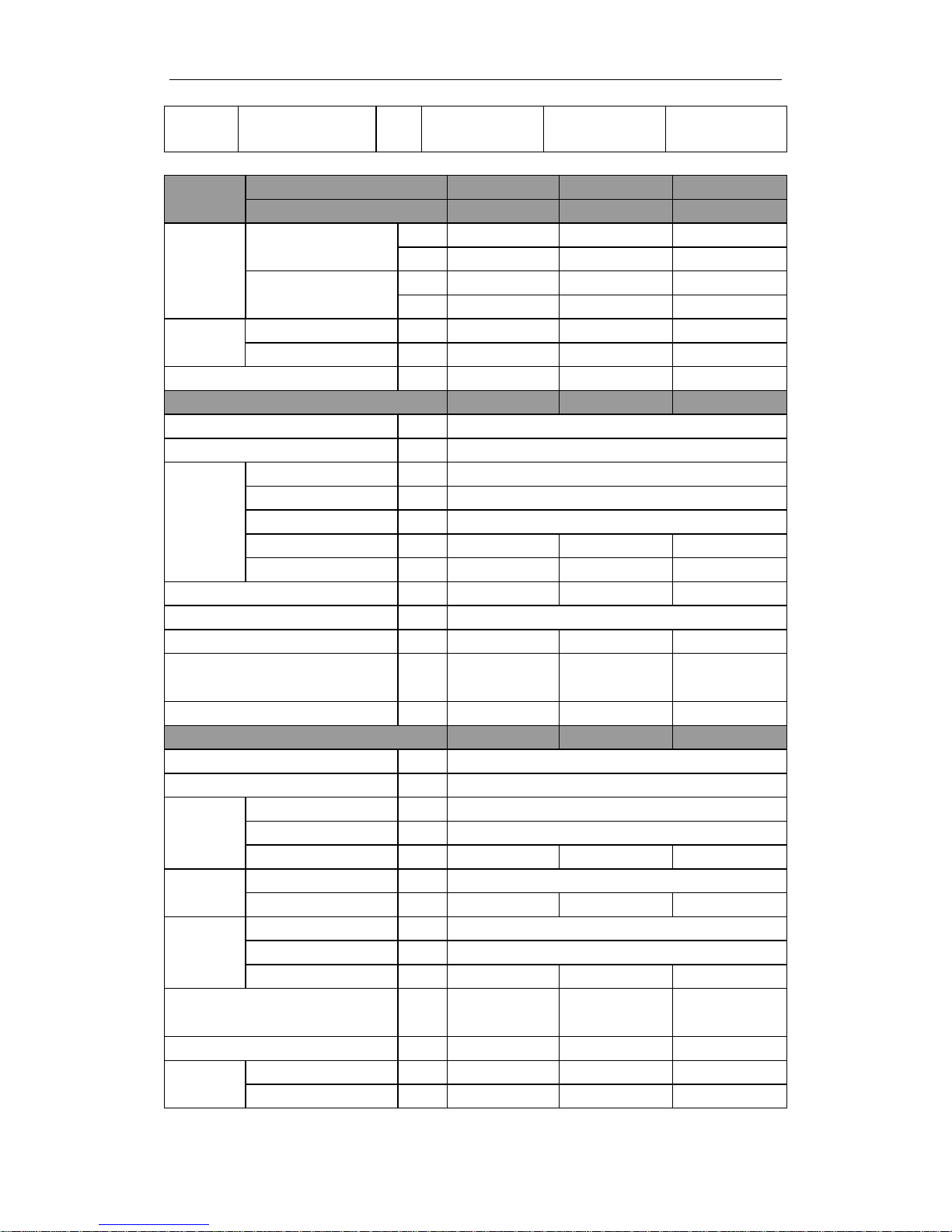
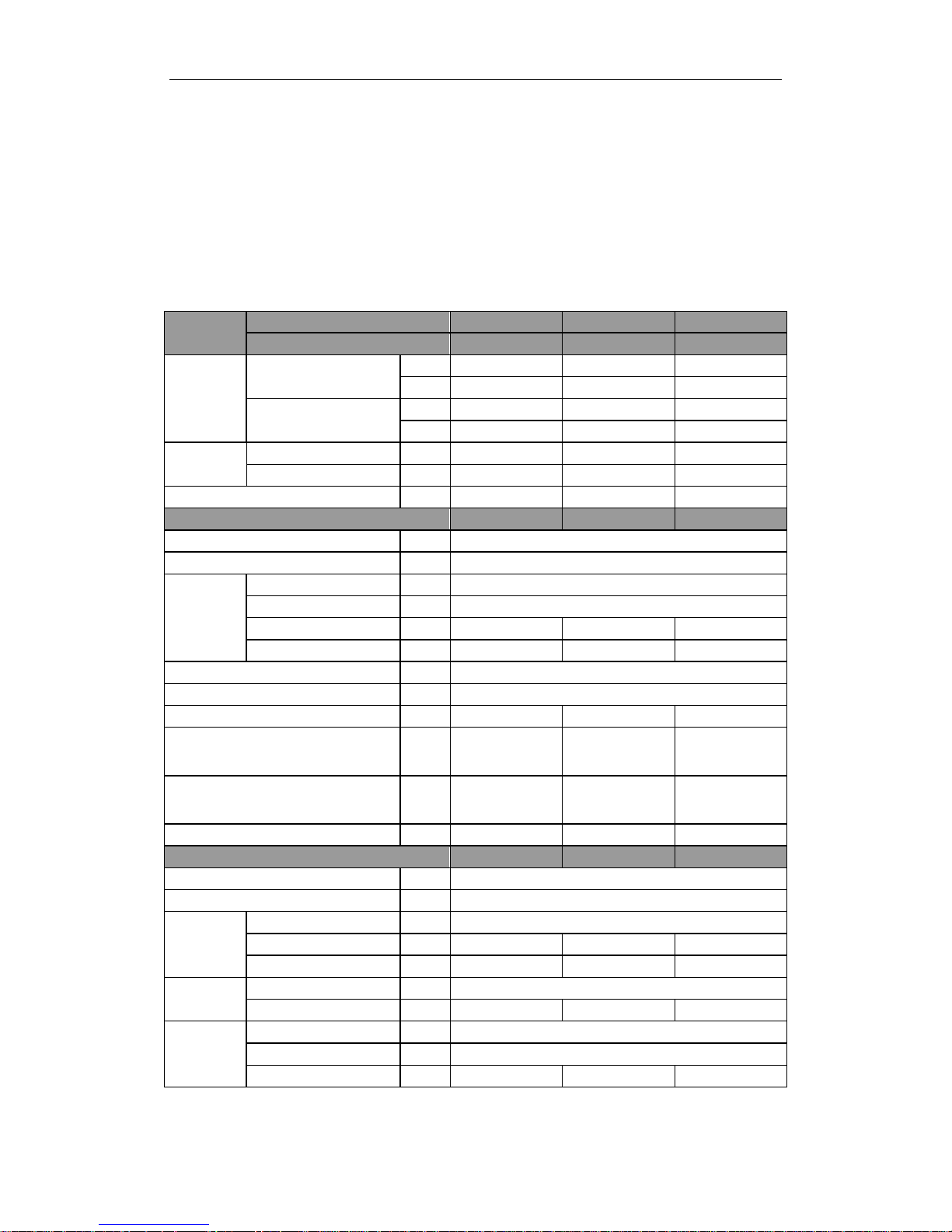
1 MODELS LIST
1.1 Outdoor Unit
Model
Nominal Capacity
Cooling/Heating
(Btu/h)
Ref.
Power
Supply
ULS-09 8870/9720 R410a
220-240,1,50
ULS-12 11940/12283 R410a
220-240,1,50
ULS-18 17060/19448 R410a
220-240,1,50
ULS-24 23884/27296 R410a
220-240,1,50
ULS-36 33437/37532 R410a
220-240,1,50
ULT-36 34120/37532 R410a
380-415,3,50
ULT-45 40944/47768 R410a
380-415,3,50
ULT-50 47768/52886 R410a
380-415,3,50
ULT-60 54592/63122 R410a
380-415,3,50
Note:1Ton =12000Btu/h = 3.517kW
U-MATCH AIR CONDITIONERS PRODUCT
3
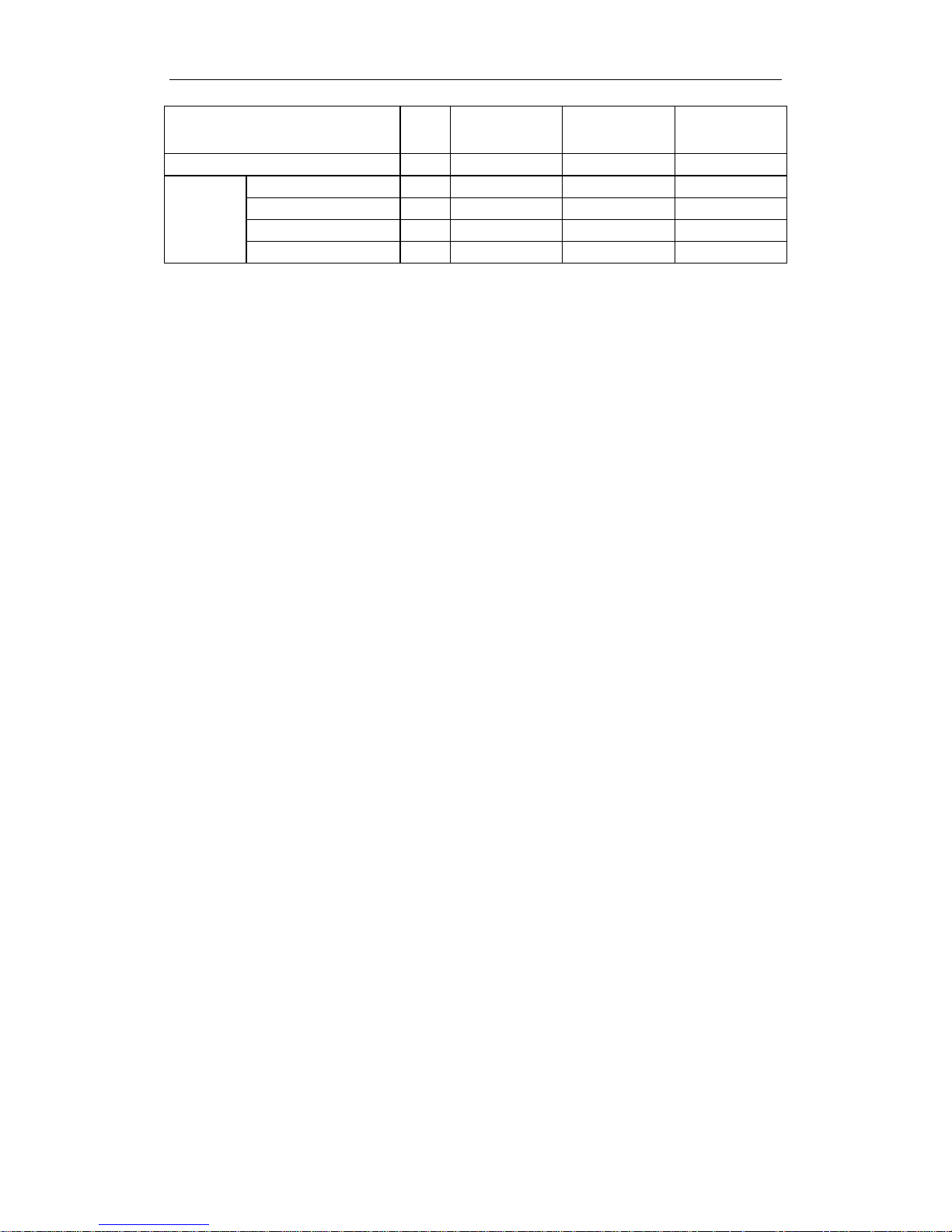
1.2 Indoor Unit
Type Model
Nominal Capacity
Cooling/Heating
(Btu/h)
Ref.
Power
Supply
Duct
Type
IDI-09 8870/9720
R410a
220-240
1Ph
50Hz
IDI-12 11940/12283
IDI-18 17060/19448
IDI-24 23880/27300
IDI-36 33437/37500
IDI-45 42000/48000
IDI-50 48000/53000
IDI-60 60000/63120
Floor-
Ceiling
Type
IKI-09 8870/9720
R410a
220-240
1Ph
50Hz
IKI-12 11940/12283
IKI-18 17060/19448
IKI-24 23880/27300
IKI-36 33437/36781
IKI-45 42000/48000
IKI-50 48000/53000
Cassette
Type
ICI-12 11940/12283
R410a
220-240
1Ph
50Hz
ICI-18 17060/19448
ICI-24 23201/25590
ICI-36 36000/37500
ICI-45 42000/48000
ICI-50 48000/53000
Note:1 Ton =12000Btu/h = 3.517kW
NOTES˖
The universal outdoor unit means that the customer can choose any of three kind of indoor unit to
match the outdoor unit without any change with it.
U-MATCH AIR CONDITIONERS PRODUCT
4
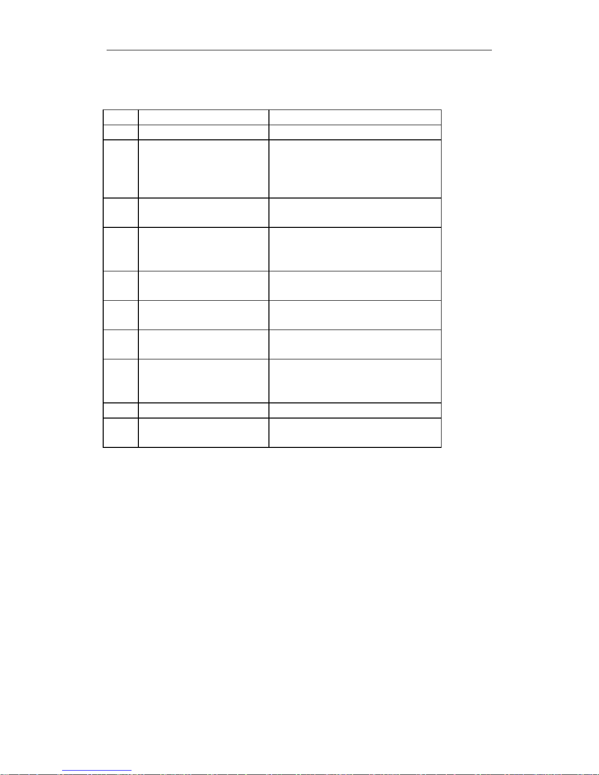
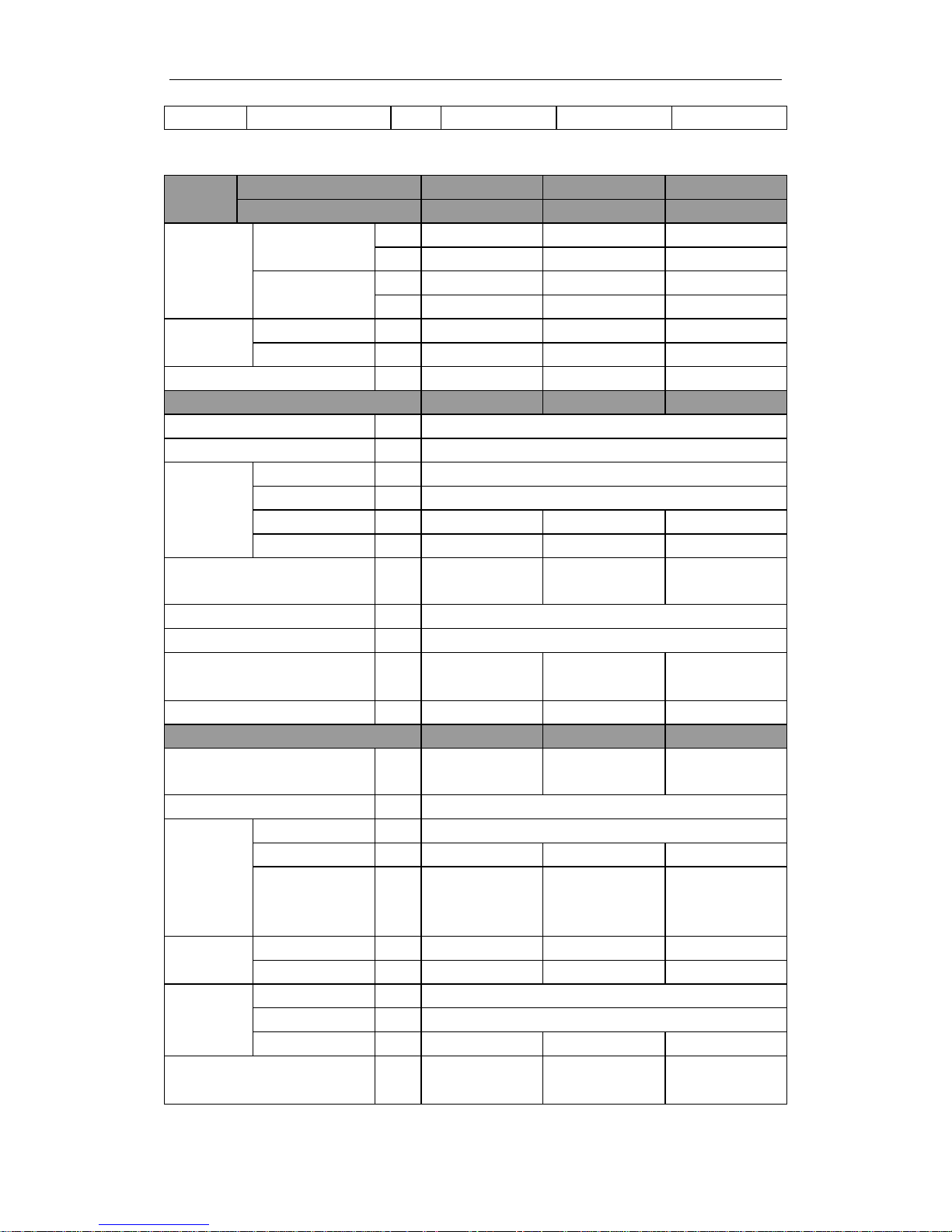
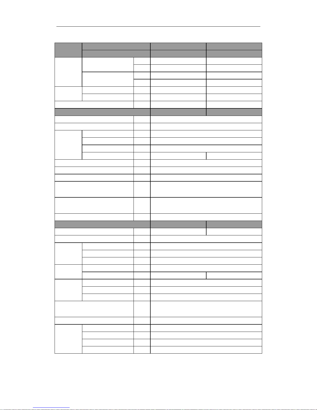
2 NOMENCLATURE
NO. Description Options
1 INVENTOR
2 Unit Type
U=Match Outdoor Unit
F=Duct Type
K=Cassette Type
T= Ceiling Type
3 Product Type
C=Cool Only
H=Heat Pump without Aux Electric Heaters
4 Power Supply Code
N=Constant Frequency
D=DC Inverter
A=AC Inverter
5 Nominal Cooling Capacity
Nominal Cooling Capacity
=Number×1000Btu/h
6 Climate Type
N=Climate T1 Condition
T= Climate T3 Condition
7 Power Supply Code
K=1Ph 220~240V 50HZ
M=3Ph 380~415V 50HZ
8 Refrigerant
1 =R22
2=R407C
3=R410A
9 Design Code Design Code:A,B,C,D……
10
Unit Code for Condensing Unit
or Indoor Unit
O=Outdoor
I=Indoor Unit
3 FUNCTION
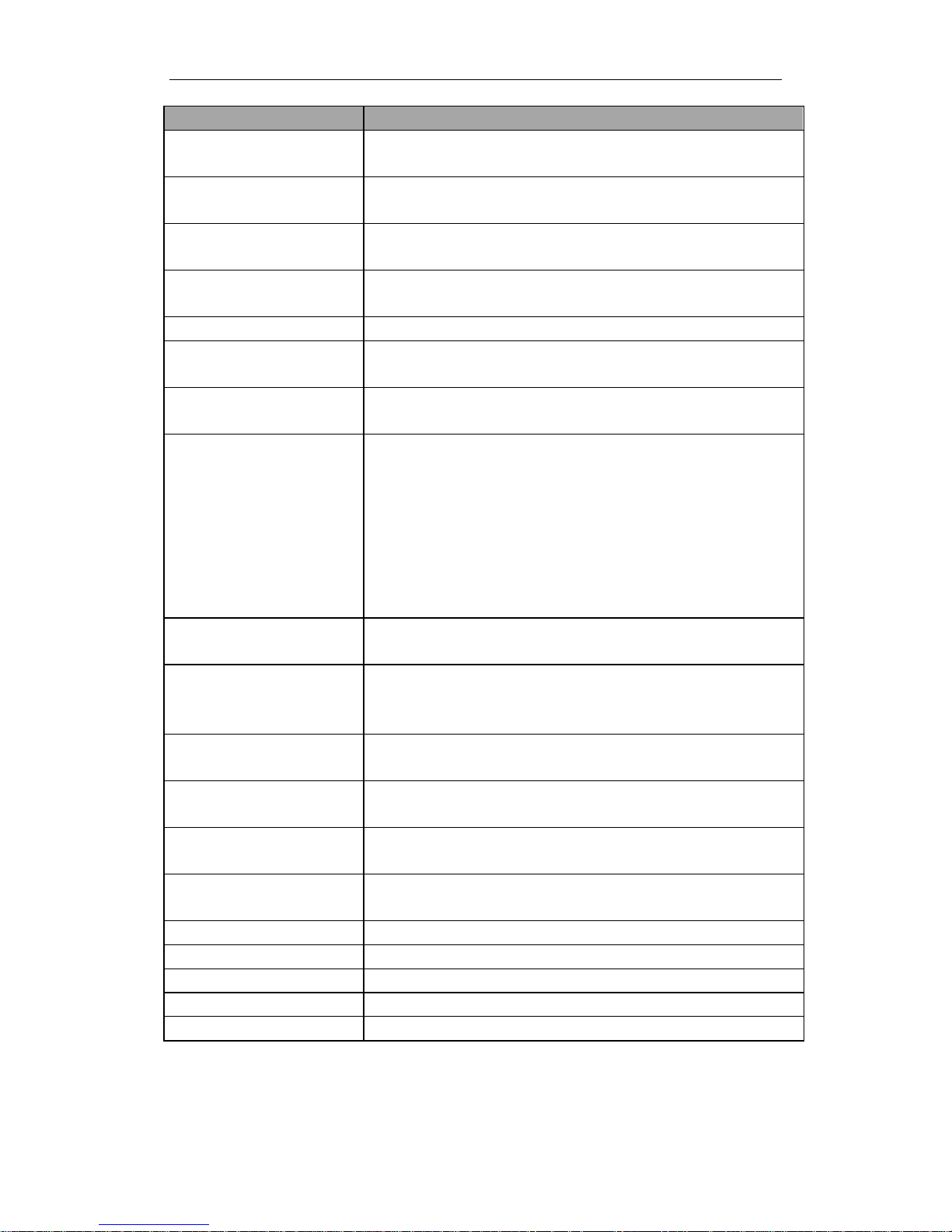
U-MATCH AIR CONDITIONERS PRODUCT
5
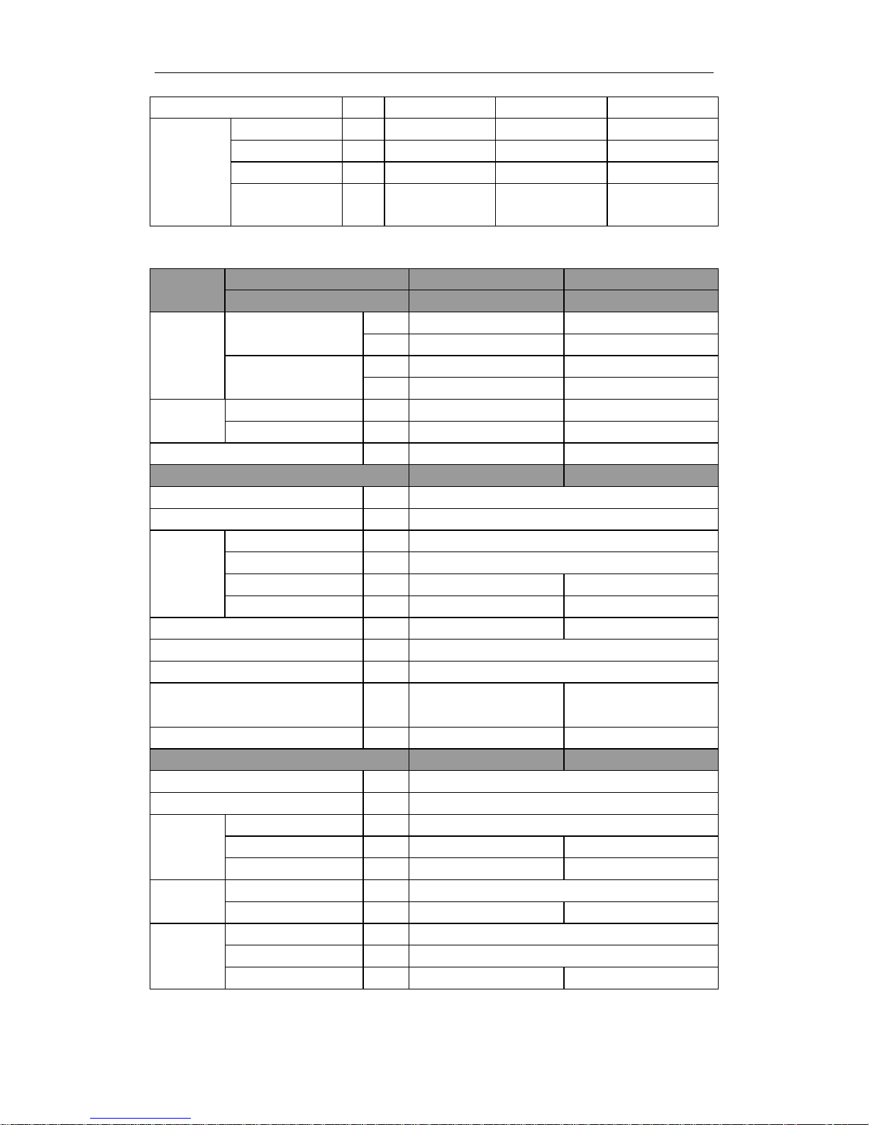
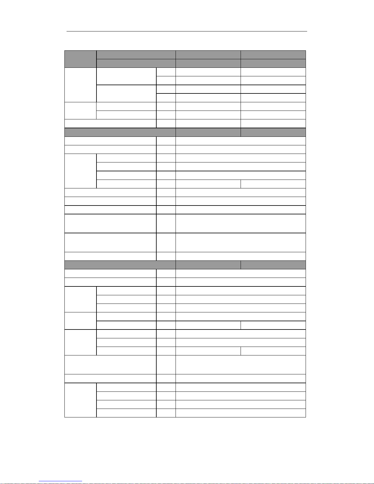
Function Description
Memory function
when unit restart after power off, it will run on former status, the mode and
parameter are kept the same
Remote control function
wireless controller and remote controller can be opted, and the maximum
control distance of remote controller is 10m.
Timing function
it can timing ON/ OFF separately, meanwhile, it can also can timing on
circularly
Self-diagnosis with alarm function
once unit has malfunction, the malfunction code will be indicated and alarm
ring immediately
Sleep function it can self control for saving energy in energy saving mode.
Automatic function
the fan of indoor unit can adjust fan speed automatically based on actual
demand when cooling or heating under automatic mode
Cool air proof function
the fan starts only when the temperature of indoor unit heat exchanger is higher
than indoor temperature under heating mode
Weekly Timer
Centralized Control and Week Timer Functions: The centralized controller and
the weekly timer are integrated in the same wire controller. The system has both
the centralized control and the week timing functions. Up to 16 sets of units can
be controlled simultaneously by the centralized controller (weekly timer). The
weekly timer has the function of invalidating the lower unit. The weekly timing
function is able to realized four timing ON/OFF periods for any unit every day,
so as to achieve fully automatic operation. No timing control can be set for
holidays.
High/low pressure protection
when suction pressure is too low or discharge pressure is too high, compressor
will stop and unit display malfunction code
Overload protection
compressor has its own overheat protection, once the temperature of compressor
is higher than allowable level, compressor will stop and only when temperature
recovery, compressor restart
Over current protection
once the current of compressor is higher that normal level, compressor will stop
and unit display malfunction code
Discharge high
temperature protection
once the discharge temperature of compressor is higher than allowable value,
compressor will stop and unit display malfunction code
Reverse (open) phase protection
once the phase sequence of power supply is incongruent or the phase is absent,
unit can’t work and display malfunction code
Anti-high
temperature protection
once the heat exchanger temperature of indoor unit is too high, compressor stop
and unit display malfunction code.
Timing ON/OFF display display and timing turn ON/OFF time
Fan speed display display the speed (high, medium, low) of fan
Function model display cooling mode, dehumidifying mode, heating mode, fan mode
Testing display display testing mode
Temperature display display room temperature and set temperature
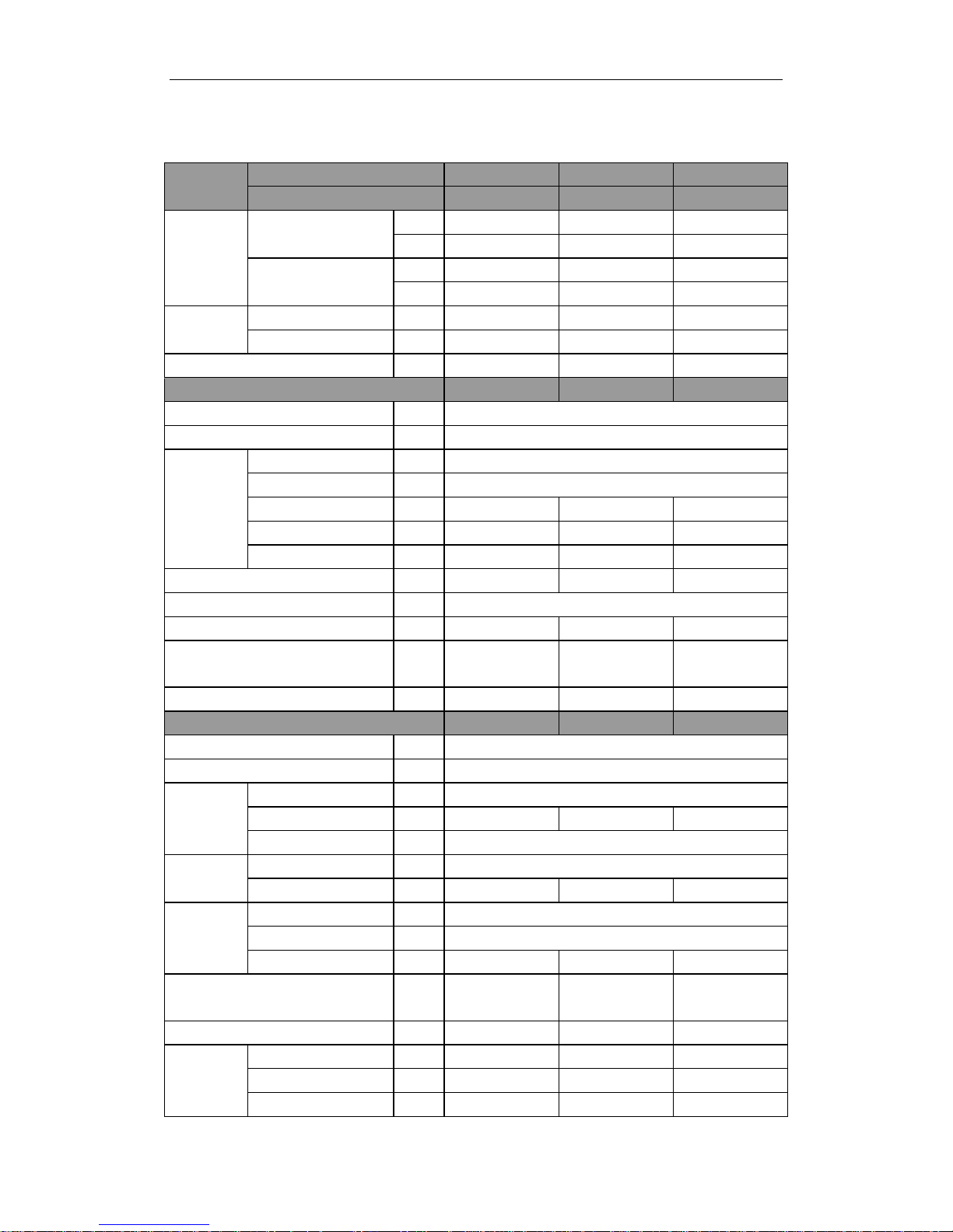
4 PRODUCT DATA
U-MATCH AIR CONDITIONERS PRODUCT
6
4.1 Product Data at Rated Condition
4.1.1 Duct Type
Model
Indoor unit IDI-09 IDI-12 IDI-18
Outdoor unit ULS-09 ULS-12 ULS-18
Nominal
Capacity
Cooling
kW 2.6 3.5 5.0
Btu/h 8870 11940 17060
Heating
kW 2.85 3.6 5.7
Btu/h 9720 12283 19448
Power
Input
Cooling kW 1.35 1.2 2.1
Heating kW 1.4 1.1 1.8
EER/COP W/W 2.6/2.94 2.92/3.55 2.38/3.22
Indoor Unit
IDI-09 IDI-12 IDI-18
Power Supply
ˉ
220-240V~/1 Ph/50HZ
Heat Exchange
ˉ
Cross Fin Coil
Fan
Type
ˉ
Centrifugal fan
Drive
ˉ
Direct Driver
Motor Output kW 0.02×2 0.02×2 0.07×2
Air Flow m3/h 550 600 840
Ext. Static Pressure Pa 25 25 40
Sound Pressure Level˄H/M/L˅
dB(A) 37 / 36 /34 40/38/36 42/40/38
Air Filter
ˉ
Standard washable synthetic
Drain Piping mm 20×1.2 20×1.2 30×1.5
Dimensions (H×W×D)
(Outline/Package)
mm
220×913×680/
258×995×750
220×913×680/
258×995×750
266×1012×736
308×1120×795
Weight˄Net/Gross˅
kg 27/32 27/32 36/39
Outdoor Unit
ULS-09 ULS-12 ULS-18
Power Supply
ˉ
220-240V~/1Ph/50HZ
Heat Exchange
ˉ
Cross Fin Coil
Fan
Type Axial fan
Motor Output kW 0.03 0.03 0.03
Fan Motor Speed rpm 850
Compressor
Type
ˉ
ROTARY
Motor Output kW 0.922 1.185 1.9
Refrigerant
Type
ˉ
R410A
Control
ˉ
Capillary Tube
Charge kg 1.1 1.0 1.5
Dimensions (H×W×D)
(Outline/Package)
mm
540×848×320/
590×878×360
540×848×320/
590×878×360
540×848×320/
590×878×360
Weight˄Net/Gross˅
kg 32/37 32/37 40/45
Piping
Connections
Liquid mm 6.35 6.35 6.35
Gas mm 9.52 12.7 12.7
Max. Length m 20 20 20
U-MATCH AIR CONDITIONERS PRODUCT
7
Max. Height Difference m 15 15 15
Continued 1
Model Indoor unit IDI-24 IDI-36 IDI-36
U-MATCH AIR CONDITIONERS PRODUCT
8
Outdoor unit ULS-24 ULS-36 ULS-36
Nominal
Capacity
Cooling
kW 7.0 9.8 10
Btu/h 23880 33437 36000
Heating
kW 8.0 11 11
Btu/h 27300 37500 37500
Power
Input
Cooling kW 2.66 4.0 4.0
Heating kW 2.51 3.5 3.5
EER/COP W/W 2.63/3.19 2.5/3.14 2.5/3.14
Indoor Unit
IDI-24 IDI-36 IDI-36
Power Supply
ˉ
220-240V~/1 Ph/50HZ
Heat Exchange
ˉ
Cross Fin Coil
Fan
Type
ˉ
Centrifugal fan
Drive
ˉ
Direct Driver
Motor Output kW 0.15×2 0.5×2 0.5×2
Air Flow m3/h 1400 2000 2000
Ext. Static Pressure Pa 80 150 150
Sound Pressure Level˄H/M/L˅
dB(A
)
44 / 42 /40
50 / 48 /46
50 / 48 /46
Air Filter
ˉ
Standard washable synthetic
Drain Piping mm 20×1.2 20×1.2 20×1.2
Dimensions (W×H×D)
(Outline/Package)
mm
1270 ×268×504/
1345×268×594
1251×290×744/
1335× 290× 834
1251×290×744/
1335× 290× 834
Weight˄Net/Gross˅
kg 37/45 57/67 57/67
Outdoor Unit
ULS-24 ULT-36 ULS-36
Power Supply
ˉ
220-240V~/1Ph/50
HZ
380-415V~/3Ph/50
HZ
220-240V~/1Ph/50
HZ
Heat Exchange
ˉ
Cross Fin Coil
Fan
Type Axial fan
Motor Output kW 0.068×1 0.092×2 0.092×2
Fan Motor
Speed(H/M/L)
rpm 840/620/400 940/840/700 940/840/700
Compress
or
Type
ˉ
ROTARY SCROLL SCROLL
Motor Output kW 2.475 3.65 3.8
Refrigeran
t
Type
ˉ
R410A
Control
ˉ
Capillary Tube
Charge kg 2.2 3.2 3.2
Dimensions (W×H×D)
(Outline/Package)
mm
1018×700× 412/
1100 ×755× 450
1018 ×8 40×412/
1110 × 985 × 450
1018 ×8 40×412/
1110 ×985 × 450
Weight˄Net/Gross˅
kg 59/64 90/100 90/100
Piping
Connectio
ns
Liquid mm 9.52 12.7 12.7
Gas mm 15.8 19.05 19.05
Max. Length m 30 50 50
U-MATCH AIR CONDITIONERS PRODUCT
9
Max. Height
Difference
m 15 30 30
Continued:2
Model
Indoor unit IDI-45 IDI-50 IDI-60
Outdoor unit ULT-45 ULS-48N ULS-60
Nominal
Capacity
Cooling
kW 12 14 16
Btu/h 42000 48000 60000
Heating
kW 14 15.5 18.5
Btu/h 48000 53000 63120
Power
Input
Cooling kW 5.3 5.8 6.5
Heating kW 4.9 5.4 5.5
EER/COP W/W 2.26/2.86 2.41/2.87 2.46/3.27
Indoor Unit
IDI-45 IDI-50 IDI-60
Power Supply
ˉ
220-240V~/1 Ph/50HZ
Heat Exchange
ˉ
Cross Fin Coil
Fan
Type
ˉ
Centrifugal fan
Drive
ˉ
Direct Driver
Motor Output kW 0.5×2
Air Flow m3/h 2000 2300 2500
Ext. Static Pressure Pa 150 150 150
Sound Pressure Level˄H/M/L˅
dB(A) 50 / 48 /46 50 / 48 /46 53 / 50 /48
Air Filter
ˉ
Standard washable synthetic
Drain Piping mm 20×1.2 20×1.2 32×1.5
Dimensions (W×H×D)
(Outline/Package)
mm
1251× 290 ×744/
1335 × 290× 834
1251×290×744/
1335× 290× 834
1251×330×788/
1334 ×330 × 882
Weight˄Net/Gross˅
kg 57/67 57/67 66/76
Outdoor Unit
ULT-45 ULT-50 ULT-60
Power Supply
ˉ
380-415V~/3 Ph/50HZ
Heat Exchange
ˉ
Cross Fin Coil
Fan
Type Axial fan
Motor Output kW 0.092×2
Fan Motor Speed(H/M/L) rpm 940/840/700 940/840/700 940/840/700
Compressor
Type
ˉ
SCROLL
Motor Output kW 4.75 4.5 5.75
Refrigerant
Type
ˉ
R410A
Control
ˉ
Capillary Tube
Charge kg 3.55 3.8 5.0
Dimensions (W×H×D)
(Outline/Package)
mm
1018×700× 412
/1100 ×755×450
950×1250×412
/1110×1385×450
950×1250×412
/1110×1385×450
Weight˄Net/Gross˅
kg 112/123 112/123 123/134
Piping
Connections
Liquid mm 12.7 12.7 12.7
Gas mm 19.05 19.05 22.2
U-MATCH AIR CONDITIONERS PRODUCT
10
Max. Length m 50
Max. Height Difference m 30
Note˖
ķ Nominal capacities are based on the follow conditions.
Indoor Outdoor
Cooling DB˖27ć(80.6)
WB˖19ć(66.2)
DB˖35ć(95)
WB˖24ć(75.2)
Heating DB˖20ć(68)
WB˖--ć(--)
DB˖7ć(44.6)
WB˖6ć(42.8)
Piping Length
5m
ĸ The air volume is measured at the relevant standard external static pressure.
Ĺ Noise is tested in the Semi anechoic Room, so it should be slightly higher in the actual
operation due to environmental change.

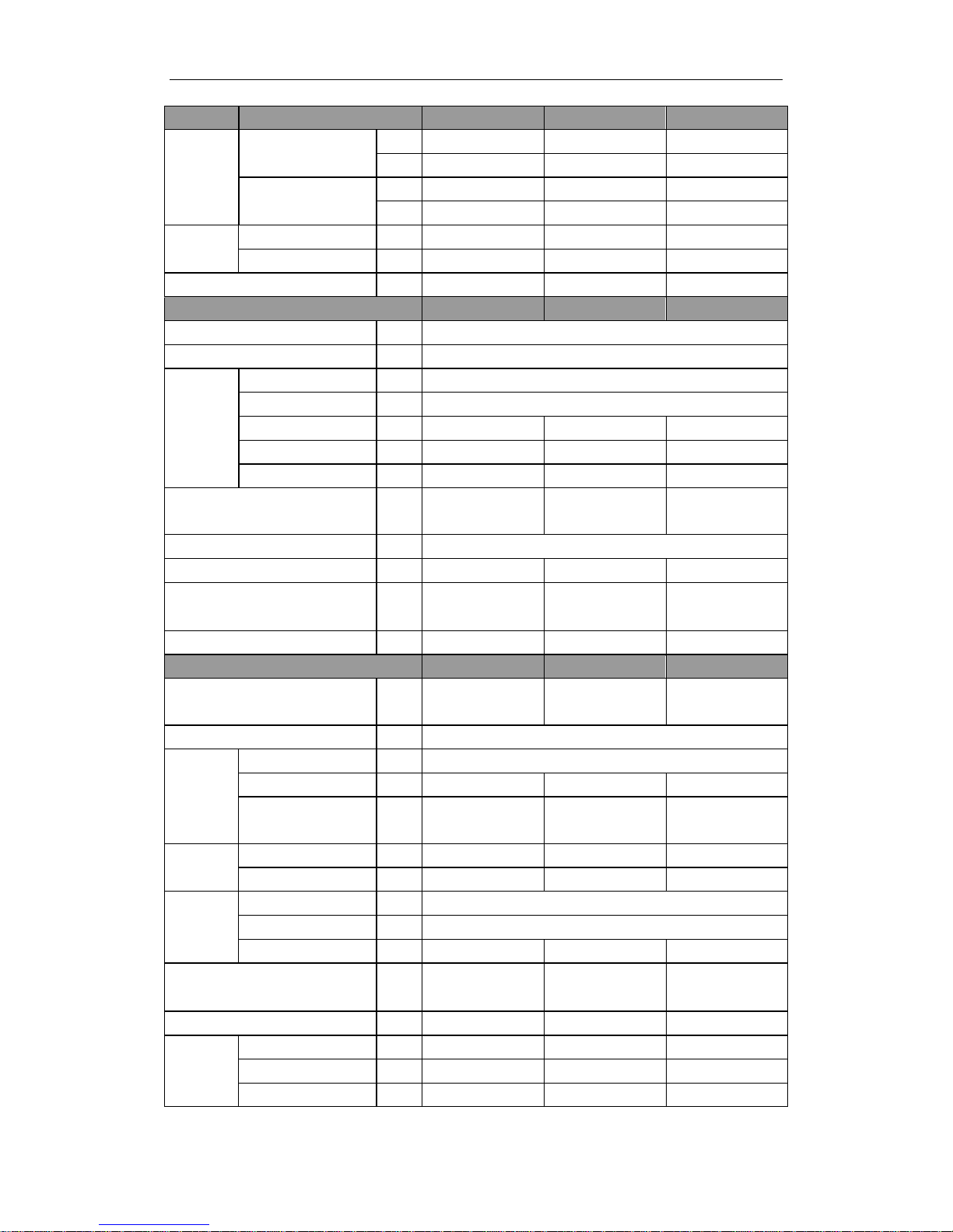
U-MATCH AIR CONDITIONERS PRODUCT
11
4.1.2 Ceiling Type
Models
Indoor unit IKI-09 IKI-12 IKI-18
Outdoor unit ULS-09 ULS-12 ULS-18
Nominal
Capacity
Cooling
kW 2.6 3.5 5.0
Btu/h 8870 11940 17060
Heating
kW 2.85 3.6 5.7
Btu/h 9720 12280 19448
Power
Input
Cooling kW 1 1.17 2.03
Heating kW 1 1.1 2.07
EER/ COP W/W 2.6/2.85 2.99/3.55 2.46/2.8
Indoor Unit
IKI-09 IKI-12 IKI-18
Power Supply
ˉ
220-240V~/1 Ph/50HZ
Heat Exchange
ˉ
Cross Fin Coil
Fan
Type
ˉ
Centrifugal fan
Drive
ˉ
Direct Driver
Motor Output kW 0.01×2 0.01×2 0.04×2
Air Flow m3/h 550 550 700
Sound Pressure Level˄H/M/L˅
dB(A) 47/44/41 46/44/41 54/50/46
Air Filter
ˉ
Standard washable synthetic
Drain Piping mm 28×1.5
Dimensions (W×H×D)
(Outline/Package)
mm
836×238×695/
935×295×805
836×238×695/
935×295×805
836×238×695/
935×295×805
Weight˄Net/Gross˅
kg 27/35.5 27/35.5 32/36
Outdoor Unit
ULS-09 ULS-12 ULS-18
Power Supply
ˉ
220-240V~/1 Ph/50HZ
Heat Exchange
ˉ
Cross Fin Coil
Fan
Type Axial fan
Motor Output kW 0.03 0.03 0.03
Fan Motor Speed rpm 850 850 850
Compressor
Type
ˉ
ROTARY
Motor Output kW 0.922 1.185 1.9
Refrigerant
Type
ˉ
R410A
Control
ˉ
Capillary Tube
Charge kg 1.1 1.0 1.5
Dimensions (W×H×D)
(Outline/Package)
mm
848×540×320
/878×590×360
848×540×320
/878×590×360
848×540×320
/878×590×360
Weight˄Net/Gross˅
kg 32/37 32/37 40/45
Piping
Connections
Liquid mm 6.35 6.35 6.35
Gas mm 9.52 12.7 12.7
Max. Length m 20 20 20
U-MATCH AIR CONDITIONERS PRODUCT
12
Max. Height Difference m 15 15 15
Continued 1
Models
Indoor unit IKI-24 IKI-36 IKI-36
Outdoor unit ULS-24 ULT-36 ULS-24
Nominal
Capacity
Cooling
kW 7.0 9.8 10
Btu/h 23880 33440 36000
Heating
kW 8.0 10.78 11
Btu/h 27300 36780 37500
Power
Input
Cooling kW 2.61 3.6 3.6
Heating kW 2.59 3.3 3.3
EER/ COP W/W 2.68/3.09 2.78/3.33 2.78/3.33
Indoor Unit
IKI-24 IKI-36 IKI-36
Power Supply
ˉ
220-240V~/1Ph/50HZ
Heat Exchange
ˉ
Cross Fin Coil
Fan
Type
ˉ
Centrifugal fan
Drive
ˉ
Direct Driver
Motor Output kW 0.1×4 0.085×2 0.085×2
Air Flow m3/h 1170 1800 1800
Sound Pressure Level˄H/M/L˅
dB(A
)
50/48/46 54/51/48
54/51/48
Air Filter
ˉ
Standard washable synthetic
Drain Piping mm 28×1.5
Dimensions (H×W×D)
(Outline/Package)
mm
1300×188×600
/1414×248×724
1590×238×695/
1714×330×830
1590×238×695/
1714×330× 830
Weight˄Net/Gross˅
kg 32/36 42/51 42/51
Outdoor Unit
ULS-24 ULT-36 ULS-24
Power Supply
ˉ
220-240V~/1Ph/50
HZ
380-415V~/3Ph/50
HZ
220-240V~/1Ph/50
HZ
Heat Exchange
ˉ
Cross Fin Coil
Fan
Type
ˉ
Axial fan
Motor Output kW 0.068 0.092×2 0.092×2
Fan
MotorSpeed(H/M/L) rpm 840/620/400 940/840/700
940/840/700
Compressor
Type
ˉ
ROTARY SCROLL SCROLL
Motor Output kW 2.475 3.65 3.8
Refrigerant
Type
ˉ
R410A
Control
ˉ
Capillary Tube
Charge kg 2.2 3.2 3.2
Dimensions (W×H×D)
(Outline/Package)
mm
1018 ×700×412/
1100×755×450
1018×840×412/
1110×985×450
1018×840×412/
1110×985×450
U-MATCH AIR CONDITIONERS PRODUCT
13
Weight˄Net/Gross˅
kg 59/64 90/100 90/100
Piping
Connections
Liquid mm 9.52 12.7 12.7
Gas mm 15.8 19.05 19.05
Max. Length m 30 50 50
Max. Height
Difference
m 15 30
30
Continued 2
Models
Indoor unit IKI-45 IKI-50
Outdoor unit ULT-45 ULT-50
Nominal
Capacity
Cooling
kW 12 14
Btu/h 42000 48000
Heating
kW 14 15.5
Btu/h 48000 53000
Power
Input
Cooling kW 4.8 6.1
Heating kW 4.7 5.8
EER/ COP W/W 2.5/2.98 2.3/2.67
Indoor Unit
IKI-45 IKI-50
Power Supply
ˉ
220-240V~/1Ph/50HZ
Heat Exchange
ˉ
Cross Fin Coil
Fan
Type
ˉ
Centrifugal fan
Drive
ˉ
Direct Driver
Motor Output kW 0.085×2 0.18×2
Air Flow m3/h 1800 2100
Sound Pressure Level˄H/M/L˅
dB(A) 54/51/48 58/55/52
Air Filter
ˉ
Standard washable synthetic
Drain Piping mm 28×1.5
Dimensions (W×H×D)
(Outline/Package)
mm
1590×238×695
1714×330×830
1590×238×695/
1714×330×830
Weight˄Net/Gross˅
kg 42/51 42/51
Outdoor Unit
ULT-45 ULT-50
Power Supply
ˉ
380-415V~/3 Ph/50HZ
Heat Exchange
ˉ
Cross Fin Coil
Fan
Type Axial fan
Motor Output kW 0.092×2 0.092×2
Fan MotorSpeed(H/M/L) rpm 940/840/700 940/840/700
Compressor
Type
ˉ
SCROLL
Motor Output kW
4ˊ75
4.5
Refrigerant
Type
ˉ
R410A
Control
ˉ
Capillary Tube
Charge kg
3ˊ55
3.8

U-MATCH AIR CONDITIONERS PRODUCT
14
Dimensions (W×H×D)
(Outline/Package)
mm
950×1250×412/
1110 ×1385× 450
950×1250×412/
1110 ×1385× 450
Weight˄Net/Gross˅
kg 112/123
Piping
Connections
Liquid mm 12.7
Gas mm 19.05
Max. Length m 50
Max. Height Difference m 30
Note˖
ķ Nominal capacities are based on the follow conditions.
Indoor Outdoor
Cooling
DB˖27ć(80.6)
WB˖19ć(66.2)
DB˖35ć(95)
WB˖24ć(75.2)
Heating
DB˖20ć(68)
WB˖--ć(--)
DB˖7ć(44.6)
WB˖6ć(42.8)
Piping Length
5m
ĸ The air volume is measured at the relevant standard external static pressure.
Ĺ Noise is tested in the Semianechoic Room, so it should be slightly higher in the actual operation
due to environmental change.
U-MATCH AIR CONDITIONERS PRODUCT
15
4.1.3 Cassette Type
Models
Indoor unit ICI-12 ICI-18
ICI-24
Outdoor unit ULS-12 ULS-18
ULS-24
Nominal
Capacity
Cooling
kW 3.5 5.0
6.8
Btu/h 11940 17060
23200
Heating
kW 3.6 5.7
7.5
Btu/h 12280 19450
25590
Power
Input
Cooling kW 1.17 2.0
2.62
Heating kW 1.1 1.9
2.5
EER/COP W/W 2.8/3.2 2.5/3.05
2.67/3.2
Indoor Unit ICI-12 ICI-18
ICI-24
Power Supply ˉ 220-240V~/1 Ph/50HZ
Heat Exchange ˉ Cross Fin Coil
Fan
Type ˉ Centrifugal fan
Drive ˉ Direct Driver
Motor Output kW 0.011 0.011
0.035
Air Flow m3/h 550 600
1180
Sound Pressure Level˄H/M/L˅ dB(A) 47/45/43
Air Filter ˉ Standard washable synthetic
Drain Piping mm 31×3 31×3
32×3
Indoor Unit Dimensions
(Outline/Package) (W×H×D)
mm
600×230×600/
848×310×678
600×230×600/
848×310×678
840×260×840/
960×310×960
Panel Dimensions
(Outline/Package) (H×W×D)
mm
50×650×650/
102×730×670
50×650×650/
102×730×670
60×950×950/
115×1040×1025
Weight˄Net/Gross˅ kg 20/27 20/27
30 / 38
Outdoor Unit ULS-12 ULS-18
ULS-24
Power Supply ˉ 220-240V~/1 Ph/50HZ
Heat Exchange ˉ Cross Fin Coil
Fan
Type Axial fan
Motor Output kW 0.03 0.03
0.068
Fan Motor Speed(H/M/L) rpm 850 850
840/620/400
Compressor
Type ˉ ROTARY
Motor Output kW 1.185 1.9
2.475
Refrigerant
Type ˉ R410A
Control ˉ Capillary Tube
Charge kg 1.0 1.5
2.2
U-MATCH AIR CONDITIONERS PRODUCT
16
Dimensions (W×H×D)
(Outline/Package)
mm
848×540×320/
878×590×360
848×540×320/
878×590×360
1018×700×412/
1100×755×450
Weight˄Net/Gross˅ kg 32/37 40/45
59/64
Piping
Connections
Liquid mm 6.35 6.35
9.52
Gas mm 12.7 12.7
15.8
Max. Length m 20 20
30
Max. Height Difference m 15 15
15
U-MATCH AIR CONDITIONERS PRODUCT
17
Continued 1
Models
Indoor unit ICI-36 ICI-36
Outdoor unit ULT-36 ULS-36
Nominal
Capacity
Cooling
kW 10 10
Btu/h 36000 36000
Heating
kW 11 11
Btu/h 37500 37500
Power
Input
Cooling kW 3.6 3.6
Heating kW 3.1 3.3
EER/COP W/W 2.78/3.55 2.78/3.33
Indoor Unit ICI-36 ICI-36
Power Supply ˉ 220-240V~/1 Ph/50HZ
Heat Exchange ˉ Cross Fin Coil
Fan
Type ˉ Centrifugal fan
Drive ˉ Direct Driver
Motor Output kW 0.06
Air Flow m3/h 1600 1800
Sound Pressure Level˄H/M/L˅ dB(A) 53/51 /48
Air Filter ˉ Standard washable synthetic
Drain Piping mm 32×3
Indoor Unit Dimensions
(Outline/Package) (W×H×D)
mm
840×320×840/
960×394×960
Panel Dimensions
(Outline/Package) (H×W×D)
mm
60×950×950/
115×1040×1025
Weight˄Net/Gross˅ kg 38/46
Outdoor Unit ULT-36 ULS-36
Power Supply ˉ 380-415V~/3Ph/50HZ 220-240V~/1Ph/50HZ
Heat Exchange ˉ Cross Fin Coil
Fan
Type Axial fan
Motor Output kW 0.092×2
Fan Motor Speed(H/M/L) rpm 940/840/700
Compressor
Type ˉ SCROLL
Motor Output kW 3.65 3.8
Refrigerant
Type ˉ R410A
Control ˉ Capillary Tube
Charge kg 3.2
Dimensions (W×H×D)
(Outline/Package)
mm
1018× 840 ×412
1110 ×985×450
Weight˄Net/Gross˅ kg 90/100
Piping
Connections
Liquid mm 12.7
Gas mm 19.05
Max. Length m 50
Max. Height Difference m 30
U-MATCH AIR CONDITIONERS PRODUCT
18
Continued 2
Models
Indoor unit ICI-45 ICI-50
Outdoor unit ULT-45 ULT-50
Nominal
Capacity
Cooling
kW 12 14
Btu/h 42000 48000
Heating
kW 14 15.5
Btu/h 48000 53000
Power
Input
Cooling kW 4.8 5.8
Heating kW 5.0 6.2
EER/COP W/W 2.5/2.8 2.3/2.67
Indoor Unit ICI-45 ICI-50
Power Supply ˉ 220-240V~/1 Ph/50HZ
Heat Exchange ˉ Cross Fin Coil
Fan
Type ˉ Centrifugal fan
Drive ˉ Direct Driver
Motor Output kW 0.06
Air Flow m3/h 1650 1700
Sound Pressure Level˄H/M/L˅ dB(A) 53/ 51 /48
Air Filter ˉ Standard washable synthetic
Drain Piping mm 32×3
Indoor Unit Dimensions
(Outline/Package) (H×W×D)
mm
840×320×840/
960×394×960
Panel Dimensions
(Outline/Package) (H×W×D)
mm
60×950×950/
115×1040×1025
Weight˄Net/Gross˅ kg 38/46
Outdoor Unit ULT-45 ULT-50
Power Supply ˉ 380-415V~/3 Ph/50HZ
Heat Exchange ˉ Cross Fin Coil
Fan
Type Axial fan
Motor Output kW 0.092×2
Fan Motor Speed(H/M/L) rpm 940/840/700
Compressor
Type ˉ SCROLL
Motor Output kW 4.75 4.5
Refrigerant
Type ˉ R410A
Control ˉ Capillary Tube
Charge kg 3.55 3.8
Dimensions (W×H×D)
(Outline/Package)
mm
950×1250×412/
1110 × 1385 ×450
Weight˄Net/Gross˅ kg 112/123
Piping
Connections
Liquid mm 12.7
Gas mm 19.05
Max. Length m 50
Max. Height Difference m 30
U-MATCH AIR CONDITIONERS PRODUCT
19
Note˖
ķ Nominal capacities are based on the follow conditions.
Indoor Outdoor
Cooling DB˖27ć(80.6)
WB˖19ć(66.2)
DB˖35ć(95)
WB˖24ć(75.2)
Heating DB˖20ć(68)
WB˖--ć(--)
DB˖7ć(44.6)
WB˖6ć(42.8)
Piping Length
5m
ĸ The air volume is measured at the relevant standard external static pressure.
Ĺ Noise is tested in the Semianechoic room, so it should be slightly higher in the actual operation due to
environmental change.
4.2 Operation Range
Mode Range of Outdoor Temperatureć ()
Cooling 18ć-43ć
-7ć-43ć(with low Ambient kit)
Heating -7ć-24ć
U-MATCH AIR CONDITIONERS PRODUCT
20
4.3 Electrical Data
Model
Compressor Fan Motor
Max. Fuse
Breaker Size
(Indoor/Outdoor)
Min.
Disconnect Size
(Indoor/Outoor)
Power
Supply
Qty. LRA RLA
Condenser
Fan Motors
Supply
Blower
Motor
V, P h , H z ˉEach Each
FLA
Each
FLA
Each
Amperes Amperes
ULS-09
IDI-09
220-240
1
50
1 18 4.28 0.27
0.18 6/10 1/5.7
IDI-09 0.09 6/10 1/5.7
ULS-12
IDI-12
1 32 5.6 0.27
0.18 6/13 1/7.3
IKI-12 0.09 6/13 1/7.3
ICI-12 0.1 6/13 1/7.3
ULS-18
ICI-18
1 40 8.8 0.27
0.63 6/20 1.5/11.3
ICI-18 0.36 6/20 1/11.3
ICI-18 0.1 6/20 1/11.3
ULS-24
ICI-24
1 60 11.2 0.61
1.35 6/25 2.5/14.6
ICI-24 0.9 6/25 1.5/14.6
ICI-24 0.32 6/25 1/14.6
ULS-36
ICI-36
1 97 18.42 0.8
4.5 10/40 5.7/23.8
ICI-36 1.35 6/40 2.5/23.8
ICI-36 0.54 6/40 1/23.8
ULT-36
ICI-36
380-415~
3
50
1 67 6.58 0.8
4.5 10/16 5.7/9.1
ICI-36 1.35 6/16 2.5/9.1
ICI-36 0.54 6/16 1/9.1
ULT-45
ICI-45
1 66 8.22 0.8
4.5 10/20 5.7/11.1
ICI-45 1.35 6/20 2.5/11.1
ICI-45 0.54 6/20 1/11.1
ULT-50
ICI-50
1 59.4 8 0.8
4.5 10/16 5.7/10.8
ICI-50 1.62 6/16 2.5/10.8
ICI-50 0.54 6/16 1/10.8
ULT-60 ICI-60 1 67 9.77 0.8 4.5 10/20 5.7/13
Notes˖
RLA˖Rated load amperes
LRA˖Locked rotor amperes
FLA˖Full load current
U-MATCH AIR CONDITIONERS PRODUCT
21
5 PIPING DIAGRAM

INVENTOR COMMERCIAL AIR CONDITION U-MATCH AIR
CONDITIONERS
22
CONTROL

U-MATCH AIR CONDITIONERS CONTROL
23
CONTROL
1 OPERATION FLOWCHART
1.1 Cooling/Dry Operation
U-MATCH AIR CONDITIONERS CONTROL
24
1.2 Heating Operation
U-MATCH AIR CONDITIONERS CONTROL
25
2 MAIN LOGIC
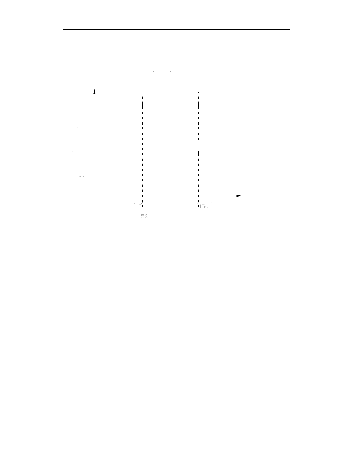
2.1 Cooling
OFF
ON
OFF
ON
OFF
OFF
OFF
OFF
OFF
H
When T
amb.Tpreset t
+1ć, the unit begins cooling operation and the compressor and the outdoor
fan are running; and the indoor fan is running at a set speed.
When T
amb.
tT
preset
-1ć, the unit is in the cooling shutdown state, and the compressor and the
outdoor fan stop running; and the indoor fan is running at a set speed.
When T
preset
-1ć˘T
amb.˘Tpreset
+1ć, the unit keeps in the operation state.
Cooling mode
Compressor
Outdoor fan
Indoor fan
4-way valve
Manual shutdown
Starting up
Operation at a set speed
Time
H grade
U-MATCH AIR CONDITIONERS CONTROL
26
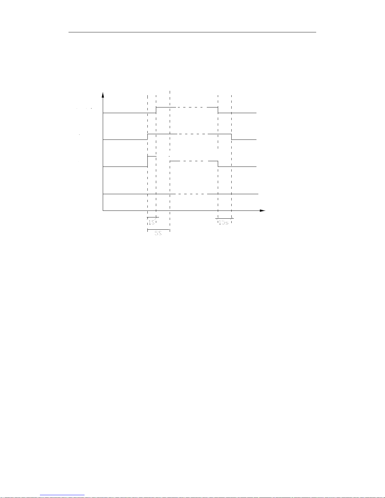
2.2 Dry Mode
OFF
ON
OFF
ON
OFF
OFF
OFF
OFF
OFF
H
When T
amb.Tpreset
+2ć, the unit begins cooling operation and the compressor and the outdoor fan
are running; and the indoor fan is running at a low speed.
When T
amb.Tpreset
-2ć, the unit is in the cooling shutdown state and the compressor and the
outdoor fan stop running.
When T
prese
-2ć˘T
amb.˘Tpreset
+2ć, the unit is in the six-minute stop and four-minute operation
state, that is, the compressor runs for 6 minutes and then stops for 4 minutes, in such cycle
repeatedly; and the indoor fan operates at a low speed.
Compressor
Outdoor fan
Indoor fan
4-way valve
Dry Mode
Manual shutdown
Starting up
Operation at a low speed
H grade
Time
U-MATCH AIR CONDITIONERS CONTROL
27
2.3 Heating Mode
OFF
ON
OFF
ON
OFF
OFF
OFF
OFF
ON
ON
OFF
OFF
OFF
OFF
ON
When T
amb.Tpreset
-1ć, the unit begins heating operation and the compressor and the outdoor fan
are running; and the indoor fan is running at a set speed according to cold fan prevention
conditions.
When T
amb.Tpreset
+1ć, the compressor and the outdoor fan stop running and the four-way valve
keeps energized; and the indoor fan is running according to afterheat blowing conditions.
When T
䇮
-1ć˘T
amb.˘Tpreset
+1ć, the unit keeps in the previous operation state.
Compressor
Outdoor fan
Indoor fan
4-way valve
Heating Mode
Manual shutdown
Starting up
Auxiliary heating
Operation at a
set speed
Operation under normal conditions
Operation in blowing
afterheat state
Cold blast prevention
Time

U-MATCH AIR CONDITIONERS CONTROL
28
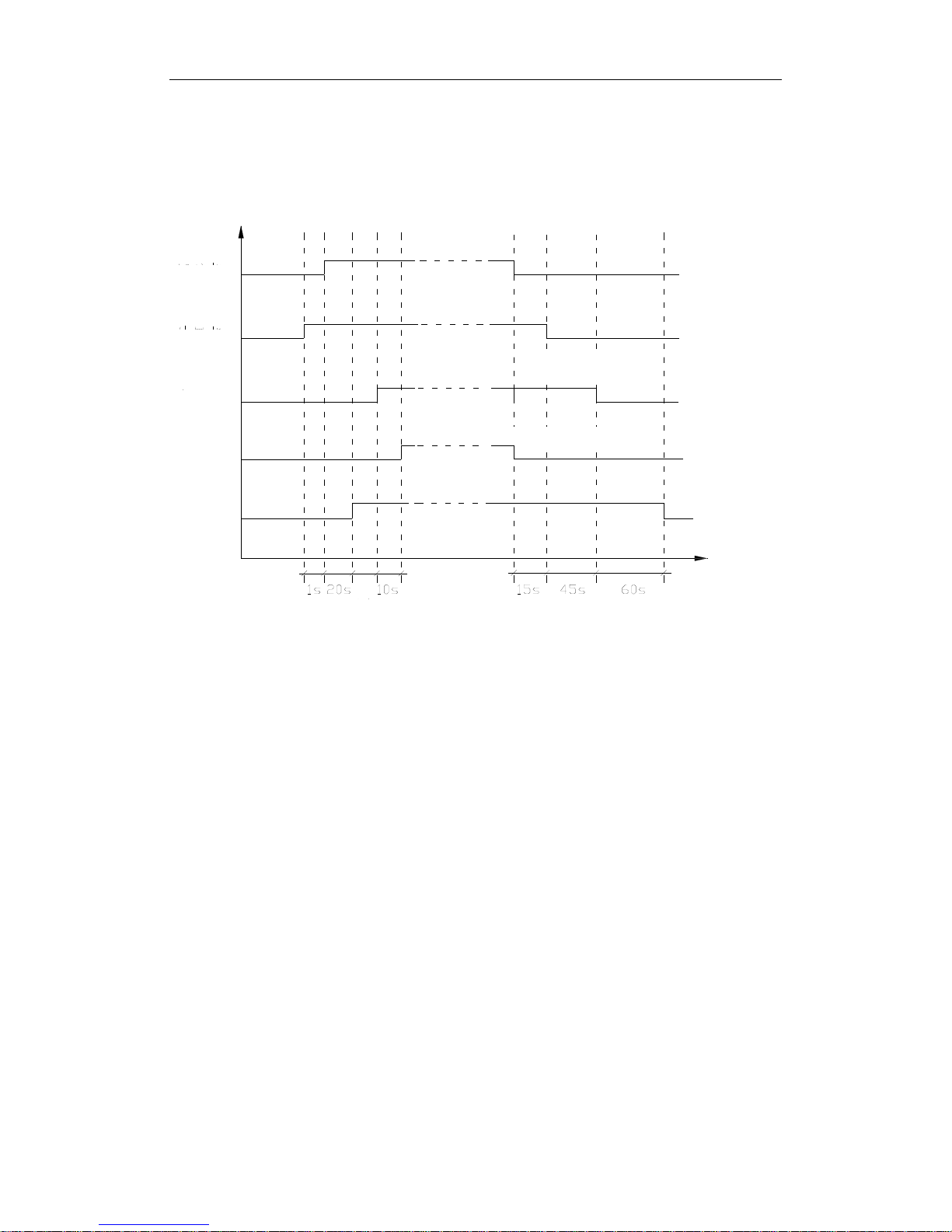
2.4 Defrosting
ON
ON
OFF
ON
OFF
OFF
OFF
ON
ON ON
ON
ON
ON
Defrosting start conditions: after the heating operation runs for an accumulated period of 44
minutes and the compressor continues to operate for 4 hours and 50 seconds, and a one-minute
duration of T
cond.
-5ćis detected, the unit begins defrosting. If an auxiliary heater is available, it
must be stopped firstly, and after 10 seconds, the four-way valve, the indoor fan, the outdoor fan
and the compressor will run compulsively.
Defrosting completion conditions: when defrosting runs 10 minutes or T
cond.
10ć, defrosting will
be completed. In such case, the four-way valve is running, the outdoor fan is running, the
compressor is running compulsively, and the indoor fan operates according to cooling fan proof
conditions.
Compressor
Outdoor fan
Indoor fan
4-way valve
Auxiliary heating
Defrosting
Enter the
defrosting mode
Withdraw the
defrosting mode
Operation at a
set speed
Operation under
normal conditions
Cold blast prevention
Time

U-MATCH AIR CONDITIONERS CONTROL
29
2.5 Fan Mode
OFF
OFF
OFF
OFF
OFF
OFF
H
The indoor fan runs at a fast speed for 5s and then runs at a set speed.
Compressor
Outdoor fan
Indoor fan
4-way valve
Fan Mode
Time
Manual shutdown
Starting up
Operation at a
set speed
H grade

U-MATCH AIR CONDITIONERS CONTROL
30
3 WIRELESS REMOTE CONTROLLER
3.1 Operation View
(1) Controller-Duct Type
212))
02'(
$872)$1
6:,1*
$872
6:,1*
23(5
$,5
)$1
NO. Name Function description
1 ON/OFF button Press the button to set start or close unit
2 Mode button
Press the button to select the mode,
cooling , heating , fan or auto mode.
3 Increase/Decrease button Press this button to increase/decrase the setup temp
4 LCD Screen Display the status of remote information
5 Swing button Press this button set swing function
6 Fan speed button Press this button to set fan speed

U-MATCH AIR CONDITIONERS CONTROL
31
(2)Controller-Cassette Type and Ceiling Type
212))
02'(
/,*+7
$872
7,0(5
212))
6:,1* +80,'
6:,1*
$XWR)DQ
6$9(
+5
$,5
)$1
23(5
7,0(5
212))
212))
$1,21
7,0(2))7,0(21
02'(
/,*+7
6/((3
6$9(
+80,'
$,5
+5
/,*+7
$872)$1
6:,1*
+80,'
$872
6:,1*
6$9(
23(5
$,5
)$1
NO. Name Function description
1 Swing button Press this button to set swing function
2 Increase/Decrease button Press this button to increase/decrase the setup temp
3 Mode button
Press the button to select the mode,
cooling , heating , fan or auto mode.
4 ON/OFF button Press the button to set start or close unit
5 LCD Screen Display the status of remote information
6 Fan speed button Press this button to set fan speed
7 Sleep button Press the button to set sleep function
8 Time on Press the button to set time on function
9 Time off Press the button to set time off function

U-MATCH AIR CONDITIONERS CONTROL
32
3.2 Display View
/,*+7
$872
7,0(5
212))
6:,1*
+80,'
6:,1*
$872)$1
6$9(
+5
$,5
)$1
23(5
No. Display Function description
1 Fan Speed
˖auto fan speed, ˖low fan speed,
˖middle fan speed ˖high fan speedˈ
2 Run Mode
˖Auto running˗ ˖Cool running˗
˖Dry Running˗ ˖Fan Running˗
˖Heat running (Heat and Cool unit only)
3 Setup temp Temperature value of setting
4 Swing function Swing is on
5 Sleep mode Sleep mode is on
6 Time value Timing value of setting
7 OPER The controller is on

U-MATCH AIR CONDITIONERS CONTROL
33
4 WIRED REMOTE CONTROLLER
4.1 Operation View
˄1˅Wired Controller-Duct Type
MODE
ON/OFF
FAN
SLEEP
TIMER
˄2˅Wired Controller-Cassette Type and Ceiling Type
MODE
ON/OFF
FAN
SWING
TIMER

U-MATCH AIR CONDITIONERS CONTROL
34
NO. Name Function description
1 MODE button
Press the button to select the mode,
cooling , heating , fan or auto mode.
2 Increasing button Press this button to increase the setup temp.
3 Decreasing button Press this button to decrase the setup temp.
4 Fan speed button Press this button to set fan speed
5 Sleep/SWING button Press the button to set sleep/swing function
6 Timer button Press the button to set timer function
7 On/off button Press the button to set start or close unit
8 Remote window Get remote information
9 LCD display Display unit information
Note˖
˄1˅ SAVE set up
˖
At unit turned off, to press the “FAN” +“” buttons continuously 5 seconds, it can come
enter save set up interphase, the unit will run at save mode.
˄2˅ FRESH valve setup : At unit is turned off, press the “ FAN” button for 5seconds,And set up the fresh air
setup.
˄3˅ Outer ambient temperature display: Under normal condition, “ENV” will display the room ambient
temperature, at unit turned on, or unit turned off status, press “SLEEP/SWING” button last for 5 seconds,
the LCD will display “OUT ENV”.
˄4˅ MEMORY function setup: At unit turned off, press “MODE” button for 10 seconds, could switch
whether turn on or off the unit state after powered off.
˄5˅ Debugging function: At unit off, continuously press “FAN” + “SLEEP” buttons lasting for 10seconds,
call out debugging menu, and displays “Debugging” icons, use “MODE” button adjust setting item, by
pressing “”, “” button to set up the detailed value.
(A) Ambient sensor set up: it can set three kinds styles.
˄6˅ Lock function: Press “”and“” at the same time for 5 seconds, the set temp. will display “EE” and
shield, all buttons will sound; and repress the“”and “”at the same time for 5 seconds, the lock
function will be released.
(for details, please read corresponding parts of manual).

U-MATCH AIR CONDITIONERS CONTROL
35
4.2 Display View
MODE
ON/OFF
FAN
SWING
TIMER
NO. Name Function description
1 Timer value Display time value
2 Timer on/off
˖display timer onˈ :display timer offˈ
3
Fan speed
display
˖auto fan speedˈ ˖low fan speedˈ
˖middle fan speedˈ ˖high fan speed
4 Set temp display
Display set temp valueˈits range is 16~30
5 Run mode display
˖auto modeˈ ˖cool modeˈ ˖dry modeˈ
˖fresh fan modeˈ ˖fan modeˈ
˖heat mode(only cool and heat unit)
6 Indoor temp display Display surrounding temp indoor
7 Outdoor temp display Display surrounding temp outdoor
8 Frost display When unit frosts ,it display
9 Sleep display Display sleep at Sleep mode
10 Swing display When setting swing function, it displays,
11 Error display When unit error, error code display

U-MATCH AIR CONDITIONERS CONTROL
36
4.3 Dimension
4.4 Installation
1. First select an installation position. According to the size of the communication line of the
wire controller, leave a recess or a embedded wire hole to bury the communication line.
2. If the communication line between the wire controller (85×85×20) and the indoor unit is
surface-mounted, use 1# PVC pipe and make matching recess in the wall (refer to Figure 6);
If concealed installation is adopted, 1# PVC pipe can be used (Refer to Figure 7).
3. No matter if surface mounting or concealed mounting is selected, it is required to drill 2 holes
(in the same level) which distance shall be the same as the distance (60mm) of installation
holes in the bottom plate of the wire controller. Then insert a wood plug into each hole. Fix
the bottom plate of the wire controller to the wall by using the two holes. Plug the
communication line onto the control panel. Lastly install the panel of the wire controller.
Caution:
During the installation of the bottom plate of the wire controller, pay attention to the direction
of the bottom plate. The plate’s side with two notches must be at the lower position, and otherwise
the panel of the wire controller cannot be correctly installed.

U-MATCH AIR CONDITIONERS CONTROL
37
39&SLSH
Fig6˖Surface Mounting of Cable Fig7˖Concealed mounting of Cable
Fig 8 Schematic Diagram of Installation
No. Name
1 Wall Surface
2 Bottom Plate of Wire Controller
3 Screw M4X10
4 Panel of Wire Controller
Caution:
1. The communication distance between the main board and the wire controller can be as far as
20m (The standard distance is 8m).
2. The wire controller shall not be installed in a place where there is water drop or large amount
of water vapor.

U-MATCH AIR CONDITIONERS CONTROL
38
5 CENTRALIZED CONTROLLER
5.1 Centralized Controller-not with week timer
5.1.1 Function
Centralized Controller-not with week timer only control on-off function of every units. Up to 16 sets of units
can be controlled simultaneously by the centralized controller-not with week timer.
5.1.2 Operation View
NO. Name Function description
1 ON button Press the button to set start unit
2 OFF button Press the button to set close unit
3 LCD display Display unit information
4 LED LED indication
5 Increasing / Decreasing button Press buttons select the unit
5.1.3 Display View
Display unit address value in the net.

U-MATCH AIR CONDITIONERS CONTROL
39
5.1.4 Dimensions
5.2 Centralized Controller-week timer
5.2.1 Function
Centralized Control and Week Timer Functions: The centralized controller and the weekly timer
are integrated in the same wire controller. The system has both the centralized control and the
week timing functions. Up to 16 sets of units can be controlled simultaneously by the centralized
controller (weekly timer). The weekly timer has the function of invalidating the lower unit. The
weekly timing function is able to realized four timing ON/OFF periods for any unit every day, so
as to achieve fully automatic operation. No timing control can be set for holidays. On and off of
every duct type unit can be done through the Timer On / Off of this WEEKLY TIMERˈit can not
set other functions except on-off function of units.

U-MATCH AIR CONDITIONERS CONTROL
40
5.2.2 Operation View
NO. Name Function description
1 ENTER button
when “enter” is pressed the setting is validate.
2 Increasing button
Press “” and selected the unit or a certain day in one week or specific value.
Press “” can set week part of time.
3 Decreasing button
Press “
” and selected the unit or a certain day in one week or specific
value. Press “
” can set week part of time.
4
CANCEL/DELETE
button
short-press “cancel/delete” to back to default page or last process, long-press
“cancel/delete” to cancel timer of a certain time period in a certain day
5
SINGLLE/GROUP
button
short-press “single/group” to enter single control setting. “SINGLE”
displayed. long-press “single/group” to enter group control setting.
“GROUP” displayed
6
TIMER/TIME
button
Short-press “timer/time” to enter timer setting.
Long-press “timer/time” under default page can begin time setting.
7 On/off button Control unit run or stop
8 LCD display Display unit information

U-MATCH AIR CONDITIONERS CONTROL
41
5.2.3 Display View
NO. Name Function description
1 unit’s no. displays Display unit’s numbers
2 Group control displays when group controls, it will display
3 Single control displays when single unit controls, it will display
4 Timer time in week displays Display time in week
5 Timer displays Display time
6 timer state displays
“on”: when set unit on, “on” will display;
“off”: when set unit off, “off” will display;
7 timer on time displays Display starts time
8 on control displays When set unit or group on, it will display,
9 off control displays When set unit or group off, it will display,
10 present time in week display Display present time of week.
11 present time in Hr:Min displays Display time of hour and minute now
12 timer off time displays Display over time
13 timer period displays Set to different time segment
Note
Please read corresponding manual of weekly timer controller to be familiar with it.

U-MATCH AIR CONDITIONERS CONTROL
42
5.2.4 Dimensions

U-MATCH AIR CONDITIONERS CONTROL
43
5.3 Field Setting
The centralized controller displays code of various units: unit code is determined by the
position (on the back of the manual operator) of the toggle switch of the manual operator on each
flue pipe air conditioner. Toggling values are corresponding to the 4-1 feet from the right to left of
the toggle switch. “ON” stands for “0”, and conversely, “OFF” stands for “1”
Example 1: to get “0111”, which represents the serial number “8”, you can put foot 1, 2 and 3
of the toggle switch to the opposite of “ON” and foot 4 to “ON”.
Example 2: to get “1010”, which represents the serial number “11”, you can put foot 2 and 4
of the toggle switch to the opposite of “ON” and foot 1 and 3 to “ON”.
Position Serial No. Position Serial No. Position Serial No. Position Serial No.
0000 1 0100 5 1000 9 1100 13
0001 2 0101 6 1001 10 1101 14
0010 3 0110 7 1010 11 1110 15
0011 4 0111 8 1011 12 1111 16
As shown in the following diagram:
ᵪ㓴㕆⸱
ᵪ㓴㕆⸱
ᵪ㓴㕆⸱
ᵪ㓴㕆⸱
ᵪ㓴㕆⸱
ᵪ㓴㕆⸱
ᵪ㓴㕆⸱
ᵪ㓴㕆⸱
ᵪ㓴㕆⸱
ᵪ㓴㕆⸱
ᵪ㓴㕆⸱
ᵪ㓴㕆⸱
ᵪ㓴㕆⸱
ᵪ㓴㕆⸱
ᵪ㓴㕆⸱
ᵪ㓴㕆⸱
Unit code:1
Unit code:2
Unit code:3
Unit code:4
Unit code:5
Unit code:6
Unit code:7
Unit code:8
Unit code:9
Unit code:10
Unit code:11
Unit code:12
Unit code:13
Unit code:14
Unit code:15
Unit code:16

U-MATCH AIR CONDITIONERS CONTROL
44
5.4 Control Wiring Design
16 Units in Max
Week timer
Wired remote controller
LCD LCD LC
Wired remote controlle
Telephone wire box Telephone wire box Telephone wire box
Twisted-wire with crystal joint
Longest distance 1200m
Corresponding relation between code switch and sequence of unit
(Note:Putting code switch to ON means 0.)
AC-L AC-N
Power supply
P S P S P S P S
0000 1 0010 5 0001 9 0011 13
1000 2 1010 6 1001 10 1011 14
0100 3 0110 7 0101 11 0111 15
1100 4 1110 8 1101 12 1111 16

INVENTOR COMMERCIAL AIR CONDITION U-MATCH AIR
CONDITIONERS
45
INSTALLATION

U-MATCH AIR CONDITIONERS INSTALLATION
46
INSTALLATION
1 INDOOR UNIT INSTALLATION
1.1 Installation of Duct Type
1.1.1 Before Installation
When the unit arrives, please check if any damage due to transport is existent. If any hurt is found on the
surface or inside, please declare to the transport company or the manufacturer in writing.
Upon receipt of the unit, the unit and accessories shall be checked in accordance with the packing list. Before
acceptance, it must be confirmed that the model is correct and the unit is in good shape and specification and
quantity of accessories are right.
Correct handling route and method shall be decided to prevent damage to the unit. For protecting the unit and
ensuring its safety, carrying the unit with its package is recommended. If such carrying method is difficult
under particular conditions, the canton shall not be removed to avoid looseness or falling during handling
Confirm the foundation is secure. When the unit is installed on the metal part of a building, electrical
insulation must be in compliance with relevant standards.
Confirm the installation position is away from storage zone of inflammable and explosive substances, or
otherwise leakage of inflammable and explosive substances may lead to explosion or a fire.
1.1.2 Installation Site
Ensure the top hanging piece has strong strength to withstand the weight of the unit.
The drainage pipe has convenient flow of water.
There is no obstacle blocking the air intake and exhaust outlet, so as to ensure sound air circulation.
The installation spaces required by the drawing must be ensured, so as to provide enough space for the
service and maintenance.
The installation site must be far away from heat source, leakage of inflammable gas or smoke.
The indoor unit is of ceiling mount (indoor unit is hidden inside the ceiling).
The indoor and outdoor units, the power cable and the connecting electrical lines must be at least 1 meter
from any TV set or radio. This is to avoid image interference or noise of the TV set or radio. (Even if the
distance is 1 meter, noise can also exist if there is strong electric wave.)
1.1.3 Caution for Installation
1
˅ Ceiling installation mode is applicable to units indoors. The suspender on the ceiling must have sufficient
intensity to bear the weight of the unit.
2
˅ Rubber cushion pads (thickness 20mm) and flexible rubber connectors must be used in the installation of
units to meet noise and vibration prevention requirements.
3
˅ Insert a M10 expansion bolt into the hole. Drive a nail into the bolt. Refer to the profile dimensions drawing
of the indoor unit for the distance between the holes. Refer to Figure 1 for the installation of the expansion
bolt
ˈas Figure 1-1-1 shows.

U-MATCH AIR CONDITIONERS INSTALLATION
47
Figure 1-1-1 Figure 1-1-2
Figure 1-1-3
4˅ Install the hanger onto the indoor unit as Figure 1-1-2 and Figure 1-1-3 shows.
5˅ Install the indoor unit at the ceiling as Figure 1-1-5shows.
Air Supply
Air Intake
Nut
Hanger
Screw
mm
I Enlargement
,
Figure 1-1-5
6˅ Precautions for unfavorable installation:
The preparation of all pipes (connecting pipes and drainage pipes) and cables (connecting lines of wire
controller, indoor unit and outdoor unit) must be ready before the installation, so as to achieve smooth
installation.
Drill an opening on the ceiling. Maybe it is required to support the ceiling to ensure the evenness of it and
avoid the vibration of it. Consult with the user or a construction company for details.
In case the strength of ceiling is not enough, use angle iron sections to set up a beam support. Place the unit
at the beam and fix it.
7˅ Level detection of indoor unit

U-MATCH AIR CONDITIONERS INSTALLATION
48
After installation of indoor unit, level detection for the complete unit must be done to ensure
levelness, as shown in Fig. 1-1-6.
Air Supply
Air Intake
i
Condensate Drainpipe
Level Instrument
Condensate Drainpipe
Enlarged View
As the inside of the unit is in the negative
pressure status, it is required to set up a
backwater elbow. The requirements is:
A=B
ıP/10+20(mm)
P is the absolute pressure inside the unit.
The unit of the pressure is Pa.
Figure 1-1-6
1.1.4 Dimension Data
Figure 1-1-7

U-MATCH AIR CONDITIONERS INSTALLATION
49
Unit
˖mm
Model A B C D E F G H I J
IDI-09
856 571 515 790 913 680 750 100 172 220
IDI-12
IDI-18 932 627 738 894 1012 736 738 125 207 266
IDI-24 1101 395 820 1159 1207 504 1002 160 235 265
IDI-36
1011 635 820 1115 1251 744 980 160 231 290
IDI-45
IDI-50
IDI-60 1015 679 820 1115 1251 788 980 160 261 330
List of Accessories for Installation of Indoor Unit
Designation and shape Qty Description
Operation and installation instructions 1
Heat insulating material for large
connector
1 For air pipe connector of indoor unit
Heat insulating material for small
connector
1
For refrigerant pipe connector of indoor
unit
Heat insulation material for drain pipe 2
For packing condensate pipe and rubber
plug
Nut with washer M8 8 For fixing the hanging hook
Nut with washer M10 4
Four sets, for hoisting the unit on the
ceiling
Nut and spring washer 4
Hanging hook 4 For hoisting the unit on the ceiling
Wire binding tie 4or 8
4 for a two-horsepower unit, 8 for other
unit.
Wire controller 1
Remote controller 1
Battery 2
Bellow
0
ˈ2 or 4
0 for a 2-powerhorse unit, 2 for a 2.5
ˉ3
horsepower unit
ˈ4 for a 4ˉ5 horsepower
unit.
Power cable
1
ˉ2
2 for a 4
ˉ5 horsepower unit and 1 for
other unit.
Connecting cable
2
ˉ3
3 for a 4
ˉ5 horsepower unit and 2 for
other unit.

U-MATCH AIR CONDITIONERS INSTALLATION
50
1.1.5 Installation Clearance Data
only for GFH24 and above models
Indoor Unit Figure 1-1-8
1.1.6 Drain Piping Work
1˅ Installation of Drainage Pipeline
A drainage outlet is located at both the left and right sides of the indoor unit. After selecting one drainage
outlet, the other outlet shall be blocked by rubber plug. Bundle the blocked outlet with string to avoid
l1eakage, and also use thermal insulation materials to wrap the blocked outlet.
When shipped out from factory, both the Drainage outlets are blocked by rubber plugs.
When connecting the drainage pipe with the unit, do not apply excessive force to the pipeline at the side of
the unit. The fixing position of the pipeline shall be near the unit.
Purchase general-purpose hard PVC pipe locally to be used as the drainage pipeline. When carrying out
connection, place the end of the PVC pipeline into the drainage hole. Use flexible drainage tube and tighten
it with thread loop. Never use adhesive to connect the drainage hole and the flexible drainage tube. (As
shown in Figure 1-1-9)
When the laid drainage pipe is used for multiple units, the common pipe shall be about 100mm lower than
the drainage outlet of each set of unit. A pipe with thicker wall shall be used for such purpose.
N
ut with washer
N
ut spring washer

U-MATCH AIR CONDITIONERS INSTALLATION
51
Sponge (gray)
Drain hose
Clamp
Clamp(attachment)
Sponge(attachment)
Below 4mm
Figure 1-1-9
2
˅ Testing of Drainage System
After the electrical installation is completed, carry out the testing of the drainage system.
During the test, check if the water correctly flows through the pipelines. Carefully observe the joints to
ensure that there is no leakage. If the unit is to be installed in a new house, carry out testing before decorating
the ceiling.
3˅ Matters of Attention
The joint of Drainage Pipeline must not have leakage.
The Drainage Pipeline shall be installed with an inclining angel of 5
10°, so as to facilitate the drainage of
condensate. The joints of the Drainage Pipeline must be covered by thermal insulation materials to avoid
generation of exterior condensate. (As shown in Figure 1-1-10)
㇑ⴆ
ߧࠍ≤㇑؍ቲ
Figure 1-1-10
1.1.7 Installation of air pipes and openings
Caution:
The air supply pipe, the air intake pipe and the fresh air pipe must be covered with a layer of thermal
insulation, so as to avoid thermal leakage and condensation. Firstly apply liquid nail on the pipes, then attach
the thermal insulation cotton with a layer of tinfoil. Use the liquid nail cover to fix it. Lastly use tinfoil
adhesive tape to carefully seal the joints; other good thermal insulation materials can also be used.
The air supply pipes and the air intake pipes shall be fixed to the prefabricated boards of the ceiling by using
Insulating layer of condensate pipe
Pipe cover

U-MATCH AIR CONDITIONERS INSTALLATION
52
iron supports. The joints of the pipes must be sealed by glue so as to avoid leakage.
The design and installation of air pipes must be in conformity with the relevant state engineering criteria.
The edge of the air intake pipe must be at least 150mm away from the wall. The air intake must be covered
with filter.
Silencing and shock absorption shall be considered in the design and installation of the air pipes. Additionally,
the noise source must be far away from where people stay. The air intake shall not be located above the place
where users stay (offices and rest places, etc.).
1
˅ Installation of air supply duct
Installation of rectangular air duct, as shown in Figure 1-1-11
䘱
仾
എ
仾
എ
仾
Figure 1-1-11
No. Designation No. Designation
1 Hanger rod 5 Filter screen
2 Return duct 6 Main air supply duct
3 Canvas duct 7 Air outlet
4 Return air inlet
Installation of circular duct, as shown in Figure 1-1-12
Return air
Return air
Supply air

U-MATCH AIR CONDITIONERS INSTALLATION
53
Figure 1-1-12
No. Designation No. Designation
1 Hanger rod 6 Transition duct
2 Air return duct 7 Air supply duct
3 Canvas duct 8 Air diffuser
4 Return air shutter 9 Connector of air diffuser
5 Air outlet
Note:
The above two diagrams show how back return air inlets are installed. Lower return air inlets shall
be used according to actual installation demands. The installation method is similar to the back
return air inlets. Among all air outlets, at least one keeps open. If circular duct is in use, air shall
be supplied to rooms through circular flexible insulating duct. Air supply duct and return duct
shall be heat insulated.
2˅ Installation of fresh air duct (only limited to excessive pressure units with refrigerating output
over 6000W)
The fresh air battle, as shown in Figure 1-1-13(a), must be removed for mounting the fresh
air duct. If the fresh air duct is not in use, gaps around the battle shall be sealed by sponge.
Circular flanges are mounted for convenient connection of the fresh air duct, as shown in
Figure 1-1-14(b)
Ducts and circular flanges must be sealed and insulated sufficiently.
Fresh air must be filtered air.

U-MATCH AIR CONDITIONERS INSTALLATION
54
(a) (b)
Figure 1-1-13
3
˅ Installation of air return duct
Square flanges at ex-factory shall be defaulted to installation at the back and the air return cover plate shall
be mounted at the lower, as shown in figure 1-1-14.
Figure 1-1-14
If lower air return is demanded, the square flange and the air return cover plate should be exchanged in their
respective position.
The air return duct shall be connected to the air return inlet on the indoor unit with rivets, and the other end
of the air return duct is connected to an air return window. To freely adjust the height, a section of canvas
duct can be fabricated and reinforced by
˔ʿ iron wires in the folding shape. A proper installation method
shall be selected by taking into overall consideration of building and maintenance conditions.
Round air duct

U-MATCH AIR CONDITIONERS INSTALLATION
55
No. Designation No. Designation
ˍ Air return window ː Indoor unit
ˎ canvas duct ˑ Air supply duct
ˏ Air return duct 6 Check grating
Figure 1-1-15
4˅ Installation of circular air supply outlet
Figure 1-1-16
1.2 Installation of Ceiling Type
1.2.1 Before Installation
When the unit arrives, please check if any damage due to transport is existent. If any hurt is found on the
surface or inside, please declare to the transport company or the manufacturer in writing.
When the unit arrives, please check if any damage due to transport is existent. If any hurt is found on the
surface or inside, please declare to the transport company or the manufacturer in writing.
Correct handling route and method shall be decided to prevent damage to the unit. For protecting the unit and
ensuring its safety, carrying the unit with its package is recommended. If such carrying method is difficult
under particular conditions, the canton shall not be removed to avoid looseness or falling during handling.
Confirm the foundation is secure. When the unit is installed on the metal part of a building, electrical
insulation must be in compliance with relevant standards.
Confirm the installation position is away from storage zone of inflammable and explosive substances, or

U-MATCH AIR CONDITIONERS INSTALLATION
56
otherwise leakage of inflammable and explosive substances may lead to explosion or a fire.
1.2.2 Installation Site
Such a place where cool air can be distributed throughout the room.
Such a place where condensation water is easily drained out.
Such a place that can handle the weight of indoor unit.
Such a place which has easy access for maintenance.
Such a place where is permitting easy connection with the outdoor unit.
Such a place where is 1m or more away from other electric appliances such as television, audio device, etc.
Avoid a location where there is heat source, high humidity or inflammable gas.
Do not use the unit in the immediate surroundings of a laundry, a bath, a shower or a swimming pool.
Be sure that the installation conforms to the installation dimension diagram.
The space around the unit is adequate for ventilation
1.2.3 Caution for Installation
Adjust the distance from the unit to the ceiling slab beforehand (Refer to Figure 1-2-1).
Fix the hanger bracket to the suspension bolt (Refer to Figure 1-2-2).
Make sure that extended suspension bolt from the ceiling stays inside the arrowed position. Readjust the
hanger bracket when it is outside the arrowed position. (Refer to Figure 1-2-3)
Suspension bolt stays inside the cap of indoor unit .Never remove the cap. Lift the unit and slide forward unit
the dent. (Refer to Figure 1-2-4)
Screw tightly both hanger bracket setting bolts (M8) (Refer to Figure 1-2-2)
Screw tightly both hanger bracket fixing bolts (M6) to prevent the movement of the indoor unit. (Refer to
Figure 1-2-2)
Adjust the height by turning the nut with a spanner. Insert the spanner from the hanger bracket opening.
(Refer to Figure 1-2-5)
Hanger bracket Figure 1-2-1 Figure 1-2-2

U-MATCH AIR CONDITIONERS INSTALLATION
57
Figure 1-2-3
Hanger bracket Figure 1-2-4
In case of hanging:
It is possible to install using inward facing hanger bracket by not removing the brackets from the
indoor unit. (Refer to Figure 1-2-6) Be sure to use only the specified accessories and parts for
installation work.
Figure 1-2-5 Figure 1-2-6
1.2.4 Dimension Data
Figure 1-2-7
Unit: mm
Model A B C D E
IKI-09
836 238 745 695 260

U-MATCH AIR CONDITIONERS INSTALLATION
58
IKI-12
IKI-18
IKI-24
1300 188 1202 600 260
IKI-36
IKI-45
IKI-50
1590 238 1491 695 260
1.2.5 Installation Clearance Data
Figure 1-2-8
1.2.6 Drain Piping Work
1˅ Installation of Drainage Pipeline
A Drainage outlet is located at both the left and right sides of the indoor unit. After selecting one Drainage
outlet, the other outlet shall be blocked by rubber plug. Bundle the blocked outlet with string to avoid
leakage, and also use thermal insulation materials to wrap the blocked outlet.
When shipped out from factory, both the Drainage outlets are blocked by rubber plugs.
When connecting the drainage pipe with the unit, do not apply excessive force to the pipeline at the side of
the unit. The fixing position of the pipeline shall be near the unit.
Purchase general-purpose hard PVC pipe locally to be used as the drainage pipeline. When carrying out
connection, place the end of the PVC pipeline into the drainage hole. Use flexible drainage tube and tighten
it with thread loop. Never use adhesive to connect the drainage hole and the flexible drainage tube. (As
shown in Figure 1-2-9)

U-MATCH AIR CONDITIONERS INSTALLATION
59
When the laid drainage pipe is used for multiple units, the common pipe shall be about 100mm lower than
the drainage outlet of each set of unit. A pipe with thicker wall shall be used for such purpose.
Sponge (gray)
Drain hose
Clamp
Clamp(attachment)
Sponge(attachment)
Below 4mm
Figure 1-2-9
2˅ Testing of Drainage System
After the electrical installation is completed, carry out the testing of the drainage system.
During the test, check if the water correctly flows through the pipelines. Carefully observe the joints to
ensure that there is no leakage. If the unit is to be installed in a new house, carry out testing before decorating
the ceiling.
3˅ Matters of Attention
The drain pipe outlet direction can be chosen from either the right rear or right.
The diameter of the drain pipe should be equal to or greater than the diameter of the connecting pipe. (Vinyl
tube; pipe size: 20mm; outer dimension: 26mm)
Keep the drain pipe short and incline downwards at a gradient of at least 1/100 to prevent air pockets. (Refer
to Figure 1-2-10)
Figure 1-2-10
No folding of drain hose inside the indoor unit. (Refer to Figure 1-2-11)
Confirm that smooth drainage is achieved after the piping work. Pour 600 cc of water into the drain pan from

U-MATCH AIR CONDITIONERS INSTALLATION
60
the air outlet for confirming drainage. (Refer to Figure 1-2-12)
Figure 1-2-11 Figure 1-2-12
1.3 Installation of Cassette Type
1.3.1 Before Installation
When the unit arrives, please check if any damage due to transport is existent. If any hurt is found on the
surface or inside, please declare to the transport company or the manufacturer in writing.
Upon receipt of the unit, the unit and accessories shall be checked in accordance with the packing list. Before
acceptance, it must be confirmed that the model is correct and the unit is in good shape and specification and
quantity of accessories are right.
Correct handling route and method shall be decided to prevent damage to the unit. For protecting the unit and
ensuring its safety, carrying the unit with its package is recommended. If such carrying method is difficult
under particular conditions, the canton shall not be removed to avoid looseness or falling during handling.
Confirm the foundation is secure. When the unit is installed on the metal part of a building, electrical
insulation must be in compliance with relevant standards.
Confirm the installation position is away from storage zone of inflammable and explosive substances, or
otherwise leakage of inflammable and explosive substances may lead to explosion or a fire.
1.3.2 Installation Site
Obstruct should put away from the intake or outlet vent of the indoor unit so that the airflow can be blown
though all the room.
Make sure that the installation had accord with the requirement of the schematic diagram of installation
spaces.
Select the place where can stand 4 times of the weight of the indoor unit and would not increase the
operating noise and oscillate.
The horizontally of the installation place should be guaranteed.
Select the place where is easy to drain out the condensate water, and connect with outdoor unit.
Make sure that there are enough space for care and maintenance. Make sure that the weight between the
indoor unit and ground is above 2300mm.
When installing the steeve bolt, check if the install place can stand the weight 4 times of the unit’s. If not,
reinforce before installation. (Refer to the install cardboard and find where should be reinforced) The
appliance shall not be installed in laundry.

U-MATCH AIR CONDITIONERS INSTALLATION
61
Cautions:
There will be lots of lampblack and dust stick on the acentric, heat exchanger and water pump in dining room and
kitchen, which would reduce the capacity of heat exchanger, lead water leakage and abnormal operation of the
water pump.
The following treatment should be taken under this circumstance:
Ensure that the smoke trap above cooker has enough capacity to obviate lampblack to prevent the indraft of
the lampblack by the air conditioner.
Keep the air conditioner far from the kitchen so that the lampblack would not be indraft by the air
conditioner.
1.3.3 Caution for Installation
1˅ Important notice:
To guarantee the good performance, the unit must be installed by professional personnel according with this
instruction.
Please contact the local INVENTOR special nominated repair department before installation. Any
malfunction caused by the unit that is installed by the department that is not special nominated by
INVENTOR would not deal with on time by the inconvenience of the business contact.
2˅ Dimension of ceiling opening and location of the hoisting screw (M10)
+DQJLQJEROWSRVLWLRQ
PP
ƶPP*ULOOHPHDVXUHPHQW
ƶPP
+DQJLQJEROWSRVLWLRQ
PP
PP
PP
ICI-12/ICI-18

U-MATCH AIR CONDITIONERS INSTALLATION
62
Figure 1-3-1
pe piantergirefR
;
ewcrng sistoiH
dsorwer scngitsi honeewte bspaG
t unirndoo I
gnng openiileiC
dsarboac efrud setarcoeD
sdare bocafd surtearcoeD
ingpeng oilinCe
itnuordon I
sdo rwe scrngtisi honeetw bepsGa
ICI-24/ICI-36/ICI-45 /ICI-50
Figure 1-3-2
The drilling of holes in the ceiling must be done by the professional personnel.
Figure 1-3-3
Cautions:
The dimension for the ceiling openings with * marks can be as large as 910mm. But the
overlapping sections of the ceiling and the decorated surface boards should be maintained at no
less than 20mm.

U-MATCH AIR CONDITIONERS INSTALLATION
63
3˅ Main body of hoisting air conditioner
Bolt ˄attachment˅
Bolt(attachment˅
[Fix the install cardboard]
Center of the ceiling
opening
Bolt of one of the angle of outlet pipe is fix
on the angle of the drainage slot
Install cardboard
Nut (supplied at scene)
Gasket (attachment)
Tighten (double nuts)
Hoisting stand
[Fix the hoisting stand firmly]
Insert
Gasket anchor board (attachment)
[Fix the gasket firmly]
Water lever
Polyethylene pipe
Figure 1-3-4
The primary step for install the indoor unit.
When attach the hoisting stand on hoisting screw, do use nut and gasket individually at the upper
and lower of the hoisting stand to fix it. The use of gasket anchor board can prevent gasket break
off.
Use install cardboard
Please refer to the install cardboard about the dimension of ceiling opening.
The central mark of the ceiling opening is marked on the install cardboard.
Install the install cardboard on the unit by bolt (3 piece), and fix the angle of the drainage
pipe at the outlet vent by bolt.
Adjust the unit to the suitable install place.
Check if the unit is horizontal.
Inner drainage pump and bobber switch are included in the indoor unit, check if 4 angle of
every unit are horizontal by water lever. (If the unit is slant toward the opposite of the coagulate
water flow, there may be malfunction of the bobber switch and lead water drop.)
Backout the gasket anchor board used to prevent gasket break off and tighten the nut on it.
Backout the install cardboard.
Cautions:
Please do tighten the nuts and bolts to prevent air conditioner break off.

U-MATCH AIR CONDITIONERS INSTALLATION
64
1.3.4 Dimension Data
Figure 1-3-5
Model H A B C D E
ICI-12
245 650 400 606 440 66
ICI-18
ICI-24 275 950 680 840 720 76
ICI-36
345 950 680 840 720 76
ICI-45
ICI-50

U-MATCH AIR CONDITIONERS INSTALLATION
65
1.3.5 Installation Clearance Data
ı
ı
ı
+
!
8QLWPP
Figure 1-3-6
Models H(mm)
ICI-12
ICI-18
230
ICI-24
260
ICI-36
ICI-45
ICI-50
320
1.3.6 Drain Piping Work
1˅ Installation of Drainage Pipeline
When connecting the drainage pipe with the unit, do not apply excessive force to the pipeline
at the side of the unit. The fixing position of the pipeline shall be near the unit.
Purchase general-purpose hard PVC pipe locally to be used as the drainage pipeline. When
carrying out connection, place the end of the PVC pipeline into the drainage hole. Use
flexible drainage tube and tighten it with thread loop. Never use adhesive to connect the
drainage hole and the flexible drainage tube. (As shown in Figure 1-3-7)
When the laid drainage pipe is used for multiple units, the common pipe shall be about
100mm lower than the drainage outlet of each set of unit. A pipe with thicker wall shall be
used for such purpose.

U-MATCH AIR CONDITIONERS INSTALLATION
66
Sponge (gray)
Drain hose
Clamp
Clamp(attachment)
Sponge(attachment)
Below 4mm
Figure 1-3-7
2˅ Testing of Drainage System
After the electrical installation is completed, carry out the testing of the drainage system.
During the test, check if the water correctly flows through the pipelines. Carefully observe
the joints to ensure that there is no leakage. If the unit is to be installed in a new house, carry
out testing before decorating the ceiling.
3˅ Matters of Attention
The diameter of the drain hose should be equal or bigger than the connection pipe’s. ( The
diameter of polythene pipe: Outer diameter 25mm Surface thickness 1.5mm)
Drain hose should be short and drooping gradient should at less 1/100 to prevent the
formation of air bubble.
If drain hose cannot has enough drooping gradient, drain raising pipe should be added.
To prevent bent of the drain hose, the distance between hoisting stand should is 1 to 1.5m.
(As shown in Figure 1-3-8)
P
ƻ(Correct) 1/100 or more gradient
h (wrong)
Figure 1-3-8
The install height of the drain raising pipe should less than 280mm.
The drain raising pipe should form a right angle with the unit, and distance to unit should not
beyond 300mm. (As shown in Figure 1-3-9)

U-MATCH AIR CONDITIONERS INSTALLATION
67
Celling
1-1.5m
Hanger bracket
Below
1120mm
Above
280mm
200mm
Drainage raising pipe
Drainage hose
(attachment)
Cassette type unit
with in 300mm
Clamp(attachment)
Figure 1-3-9
The slant gradient of the attached drain hose should be within 75mm so that the drain hole
doesn’t has to endure the unnecessary outside force. (As shown in Figure 1-3-10)
Drain hose(attachment)
Below75mm
Below500mm
Figure 1-3-10
Please install the drain hose according to the following process if several drain hoses join
together. (As shown in Figure 1-3-11)
T-tie in join drain hose
Above100mm
The specs of the selected join drain hose should fits the running capacity of the unit.
Figure 1-3-11
Check the smoothness of drain after installation.
Check the drain state by immiting 600cc water slowly from the outlet vent or test hole. (As
shown in Figure 1-3-12)
Check the drain in the state of refrigerating after installation of the electric circuit.

U-MATCH AIR CONDITIONERS INSTALLATION
68
Test hole cover
Drain hose
< Immiting water from the rest hole>
$ERYHPP
Drain vent for repair use (plastic
stopper is included) (drain the water
in waterspout by this outlet vent)
[Way of immiting]
Test hole
<Immiting water from the outlet
vent terminal>
Plastic water pot (The length of the
pipe should be about 100mm.)
Figure 1-3-12
1.3.7 Installation of panel
1˅ Set the panel to the indoor unit body by matching the position of the swing flap motor of the
decoration panel to the piping position of the panel to the piping position of the indoor unit as
shown in Figure 1-3-13.

U-MATCH AIR CONDITIONERS INSTALLATION
69
Figure 1-3-13
Hang the latch, which is located on the opposite side of the swing flap motor on the panel,
temporarily to the book of the indoor unit. (2 Positions)
Temporarily hang the remaining 2 latches to the hooks on the sides of the indoor unit.(Be
careful not to let the swing motor lead wire get caught in the sealing material.)
Screw all 4 hexagon head screws located right beneath the latches in approximately
15mm.(Panel will rise)
Adjust the panel by turning it to the arrowed direction in Fig.4 so that the ceiling opening is
completely covered.
Tighten the screws until the thickness of the sealing material between the panel and the
indoor unit body is reduced to 5~8 mm.

U-MATCH AIR CONDITIONERS INSTALLATION
70
2˅ Precautions:
Improper screwing of the screws may cause the troubles shown in Figure 1-3-14.
Figure 1-3-14
If gap is still left between the ceiling and the panel after screwing the screws, readjust the
height of the indoor unit body (Refer to Figure 1-3-15)
Figure 1-3-15
After fixing be sure no gap left between the ceiling and the panel
3˅ Wiring of the decoration panel.
Connect the joints for swing flap motor lead wire (at 2 places) installed on the panel (Refer to
Figure 1-3-16)
Figure 1-3-16

U-MATCH AIR CONDITIONERS INSTALLATION
71
2 OUTDOOR UNIT INSTALLATION
2.1 Before Installation
When the unit arrives, please check if any damage due to transport is existent. If any hurt is
found on the surface or inside, please declare to the transport company or the manufacturer in
writing.
Upon receipt of the unit, the unit and accessories shall be checked in accordance with the
packing list. Before acceptance, it must be confirmed that the model is correct and the unit is
in good shape and specification and quantity of accessories are right.
Correct handling route and method shall be decided to prevent damage to the unit. For
protecting the unit and ensuring its safety, carrying the unit with its package is recommended.
If such carrying method is difficult under particular conditions, the canton shall not be
removed to avoid looseness or falling during handling.
Confirm the foundation is secure. When the unit is installed on the metal part of a building,
electrical insulation must be in compliance with relevant standards.
Confirm the installation position is away from storage zone of inflammable and explosive
substances, or otherwise leakage of inflammable and explosive substances may lead to
explosion or a fire.
2.2 Installation Site
To ensure the unit in proper function, selection of installation location must be in accordance
with following principles:
Outdoor unit shall be installed so that the air discharged by outdoor unit will not r eturn and
that sufficient space for repair shall be provided around the unit.
The installation site must have good ventilation, so that the outdoor unit can take in and
exhaust enough air. Ensure that there is no obstacle for the air intake and exhaust of the
outdoor unit. If there is any obstacle blocking the air intake or exhaust, remove it.
Place of installation shall be strong enough to support the weight of outdoor unit, and it shall
be able to insulate noise and prevent vibration. Ensure that the wind and noise from the unit
will not affect your neighbors.
Avoid direct sunshine over the unit. It is better to set up a sun shield as the protection.
Place of installation must be able to drain the rainwater and defrosting water.
Place of installation must ensure the unit will not be buried under snow or subject to the
influence of rubbish or oil fog.
The installation site must be at a place where the air exhaust outlet does not face strong wind.
Outdoor unit should be hoisted through indicated hoisting holes. During hoisting, special
attention must be paid to the unit to prevent collision into its sheet metal parts to avoid rust.
Rubber cushion or spring shock absorber shall be used for outdoor unit to avoid excessive
noise and vibration.
Rubber cushion or spring shock absorber shall be used for outdoor unit to avoid excessive
noise and vibration.
Only professional personnel are allowed for unit installation.
2.3 Caution for Installation

U-MATCH AIR CONDITIONERS INSTALLATION
72
Installation of outdoor unit shall not allow discharged air to return, and sufficient
maintenance space shall be left around the unit.
Installation position must be well-ventilated, enabling the unit to absorb and discharge
enough air. Inlet and outlet must be free of obstruction. Any obstacle blocking air going in
and out must be removed.
When outdoor unit is mounted on the secure floor such as concrete, bolts and nuts in M10
can used for fixing the unit. Uprightness or levelness of the unit must be ensured.
Outdoor unit should be hoisted through indicated hoisting holes. During hoisting, special
attention must be paid to the unit to prevent collision into its sheet metal parts to avoid rust.
Rubber cushion or spring shock absorber shall be used for outdoor unit to avoid excessive
noise and vibration. Uprightness or levelness must be ensured.
In installation of drain pipe, the connector of the drain pipe shall be inserted into a drain hole
on the chassis of the outdoor unit. And then a drain pipe shall be connected to the drain
connector. (If the drain connector is used, installing height of the outdoor unit shall be at least
5cm).
If pipe is put through wall, a wall pipe must be used.
Installation dimension must be in line with requirements by the instructions. Outdoor unit
must be fixed on the mounting position.
Only professional personnel are allowed for unit installation
2.4 Dimension Data
Figure 2-4-1

U-MATCH AIR CONDITIONERS INSTALLATION
73
Unit
˖mm
Model A B C H D
ULS-09
848 320 540 540 286
ULS-12
ULS-18
ULS-24 1018 412 700 572 300
ULS-36
1018 412 840 572 378
ULT-36
ULT-45
950 412 1250 572 378
ULT-50
ULT-60
2.5 Installation Clearance Data
Figure 2-5-1

U-MATCH AIR CONDITIONERS INSTALLATION
74
3 REFRIGERATION PIPING WORK
3.1 Refrigeration Piping Work Procedures
1˅ Connecting pipelines
Connection pipes must be in accordance with the following requirements: the basic principle
--- keeping dry, clean and no leakage inside.
Figure 3-1-1
Align copper pipe flare with the center of screwed connector and tighten fully the nut of the
flare by hand.
Tighten the flare nut with a torque spanner until the torque spanner makes a click, as shown
in Figure 3-1-1. Moment needed for tightening a nut is shown in Tab. 3-1-1.
Figure 3-1-2
Form 3-1-1 the tightening torque needed for tightening nut
Pipe diameter Tightening torque
1/4ʾ
15-30 (N·m)
3/8ʾ
35-40 (N·m)
5/8ʾ
60-65 (N·m)
1/2ʾ
45-50 (N·m)
3/4ʾ 70-75 N·m)

U-MATCH AIR CONDITIONERS INSTALLATION
75
Curvature of piping shall not be too small, or otherwise piping may be broken. So installation
personnel should use a pipe bender to bend pipes.
Upward or longitudinal welding joint method is usually applied to the welding of pipelines.
The welding method that mouth of pipe is downward (face-down welding) should be avoided
as far as possible, because such method is prone to welding defects and even would cause
leakage, as shown in Figure 3-1-3.
Figure 3-1-3
Uninsulated connecting pipes and connectors should be packed with sponge and tied with
plastic adhesive tapes.
2˅ Vacuum-pumping and leak detection
Dismantle the bonnet of refrigerant valve and air valve.
Align with the center of piping and adequately tighten nuts of connecting pipes by hand
Tighten the nuts with a spanner.
Remove the one way valve cap of air valve.
Unscrew the spool of refrigerant valve for 1/4 turn with a socket head wrench, and at the
same time push up the spool of air valve with a screwdriver to let air give off.
Air exhaust continues for 15 seconds until coolant gas appears, immediately shut off one way
valve and tighten the valve cap.
Totally open the spool of refrigerant valve and air value (as shown in Figure 3-1-4)
Figure 3-1-4

U-MATCH AIR CONDITIONERS INSTALLATION
76
Tighten the valve caps and use soapy water or a leak detector to check any leakage on indoor
unit, outdoor unit and connection parts of pipes.
Caution
˖
If conditions are allowed, a vacuum pump shall be used for drawing off air inside the system at a
valve. Method for creation of vacuum by using a vacuum pump is as follows:
Take out the nut cover of the inlet for refrigerant.
Connect the tube of the vacuum watch with the vacuum pump, having the low-pressure end
linking to the inlet for refrigerant. (As shown in Figure 3-1-5)
Figure 3-1-5
Starting the vacuum pump, when the indicator turns to-1 bar, closing the low pressure handle
and stopping vacuumize. Keep for 15 minutes, ensuring the pressure of the vacuum watch
remains.
Take out the valve cover of the gas valve together with the liquid valve.
Loosing the cord of liquid valve until the pressure rise to 0 bar.
Dismantle the tube from the cover of the inlet for refrigerant then, tighten the cover.
Loose the valve cord of the gas valve as well as the liquid valve entirely.
Tighten the valve cover of the gas valve and liquid valve so as to check whether leakage
occurred.
3) Installation of Protective Layer of Connecting Pipe
To avoid generation of condensate on the connecting pipe and avoid leakage, the big pipe and
the small pipe of the connecting pipe must be covered by thermal insulation materials, be
bundled by adhesive tape, and be isolated from air.
The joint connecting to the indoor unit must be wrapped by thermal insulation material.
There shall be no gap between the connecting pipe joint and the wall of the indoor unit. Refer

U-MATCH AIR CONDITIONERS INSTALLATION
77
to Figure 3-1-6.
Figure 3-1-6 Figure 3-1-7
Use adhesive tape to bundle the connecting pipe and the cables together. To prevent
condensate from overflowing out from the drainage pipe, separate the drainage pipe firm the
connecting pipe and the cables.
Use thermal insulation tape to wrap the pipes from the bottom of the outdoor unit until the
upper end of the pipe where the pipe enters the wall. When wrapping thermal insulation tape,
the later circle of tape must cover half of the front circle of tape (Figure 3-1-7).
Wrapped pipe must be fixed to wall using pipe clamps.
Caution:
After the pipes are wrapped by protective materials, never bend the pipes to form very small
angle, and otherwise the pipes may crack or break.
Do not wrap the protective tape too tight, otherwise the efficiency of thermal insulation may
be decreased. Ensure that the condensate drainage flexible tube is separate from the bundled
pipes.
After the protective work is completed and the pipes are wrapped, use seal material to block
the hole in the wall, so as to prevent rain and wind from entering the room.
3.2 Caution in Connecting Pipes
Arrangement of connecting pipes shall be performed according to sit conditions with reference to
the following principles.
Try to shorten the length of connecting pipes, within 5m for the better.
Try to reduce height difference between indoor unit and outdoor unit.
Try to reduce number of joint bends of connecting pipes.
If the length of connecting pipes is more than 20m, adequacy of lubricant of the system must
be checked; and if necessary, add more lubricant properly.
Filling amount of refrigerant in the system is matched to a 7m connecting pipe. If the

U-MATCH AIR CONDITIONERS INSTALLATION
78
connecting pipe is needed to lengthen, appropriate amount of refrigerant should be added.
How much refrigerant should be added for every meter extension refers to the following table.
Allowable maximum pipe length is 30m.
If height difference between indoor unit and outdoor unit exceeds 10m in installation of air
conditioner, an oil return bend must be mounted at an interval of 6m.
If heights of indoor unit and outdoor unit are different, pipes should be laid out with reference
to Figure 3-2-1.
Refrigerant pipe (thin)
- - - - - - Air pipe (large)
Figure 3-2-1
3.3 Specification of Connection Pipe
Model
External Diameter
Maximum
Length
of Connection
Pipe
Maximum Difference
in Height between
Outdoor and Indoor
Unit
Additional
Charge
of
Refrigerant
Gas Pipe Liquid Pipe
(m) (m) (g/m)
ULS-09
3/8
ʾ
1/4
ʾ
20 15 15
ULS-12
1/2
ʾ
ULS-18
ULS-24
5/8
ʾ 3/8ʾ
30 15 60
ULS-36
3/4
ʾ 1/2ʾ
50 30 120
Refrigerant pipes
Air pipe
Outdoor unit
Oil loop of air pipe
Oil loop of air pipe
An oil loop is arranged at a
n
interval of 4-6m.
indoor unit

U-MATCH AIR CONDITIONERS INSTALLATION
79
ULT-36
ULT-45
ULT-50
ULT-60
7/8
ʾ
4 ELECTRIC WIRING WORK
4.1 Wiring Principle
4.1.1General
Perform wiring of the power supply in conformance with the regulations of the local electric
company.
For the control wires connecting indoor units, and between indoor and outdoor units, use of
double-core shield wires is recommended to prevent noise trouble.
Be sure to set the earth leakage breaker and the switches to the power supply section of the
indoor unit.
Supply power to each outdoor unit and provide an earth leakage breaker or hand switch for
each outdoor unit.
Store wiring system for control and refrigerant piping system in the same line.
Arrange the cables so that the electric wires do not come to contact with high-temperature
part of the refrigerant pipe; otherwise coating melts and an accident may be caused.
Do not turn on power of the indoor unit until vacuuming of the refrigerant pipe will finish.
Installation should be conducted by National Wiring Regulation.
The rated voltage and exclusive power supply must be adopted for the air conditioners.
The power cable should be reliable and fixed, in order to avoid the wiring terminal be
suffered from force. And do not drag the power cable forcibly.
The wire diameter of power cable should be large enough, if power cable and connection
wire be damaged, it should be replaced by the exclusive cable.
All electric installation must be done by professional personnel according to local law,
regulation and this manual.
It should be reliably earthed, and it should be connected to the special earth device, the
installation work should be operated by the professional.
The creepage protect switch and air switch must be installed.
Air switch should have the thermal dropout and magnetic dropout function, in order to avoid
the short circuit and overload.
The on spot connection should refer to the circuit diagram, which is stuck on the unit body.
The unit should be reliably earth, if it is improperly earthed that may cause electric shock or
fire.

U-MATCH AIR CONDITIONERS INSTALLATION
80
Air conditioner is the “I” class electric appliance, thus please do conduct reliable grounding
measure.
The yellow-green two-color wiring of air conditioner is grounding wire and cannot be used
for other purposes. It cannot be cut off and be fixed by screw, otherwise it would cause
electric shock.
The user must offer the reliable grounding terminal. Please don’t connect the grounding wire
to the following places:
ķ Water pipe˗
ĸ Gas pipe˗
Ĺ Blowing pipe˗
ĺ Other places that professional personnel consider them unreliable.
4.1.2 Connection of electric wires with the terminal
1˅ Caution
Before installing the electrical equipment, please pay attention to the following matters which
have been specially pointed out by our designers:
ķ Check to see if the power supply used conforms to the rated power supply specified on the
nameplate.
ĸ The capacity of the power supply must be large enough. The section area of fitting line in the
room shall be larger than 2.5mm2.
Ĺ The lines must be installed by professional personnel.
ĺ An electricity leakage protection switch and an air switch with gap between electrode heads
larger than 3 mm shall be installed in the fixed line.
2˅ Connection of single wire
ķ Use wire stripper to strip the insulation layer (25mm long) from the end of the single wire.
ĸ Remove the screw at the terminal board of the air-conditioning unit.
Ĺ User pliers to bend the end of the single wire so that a loop matching the screw size is formed.
ĺ Put the screw through the loop of the single wire and fix the loop at the terminal board.
3˅ Connection of multiple twisted wires
ķ Use wire stripper to strip the insulation layer (10mm long) from the end of the multiple
twisted wires.
ĸ Remove the screw at the terminal board of the air-conditioning unit.
Ĺ Use crimping pliers to connect a terminal (matching the size of the screw) at the end of the
multiple twisted wires.
ĺ Put the screw through the terminal of the multiple twisted wires and fix the terminal at the
terminal board.

U-MATCH AIR CONDITIONERS INSTALLATION
81
Warning:
If the power supply flexible line or the signal line of the equipment is damaged, only use
special flexible line to replace it.
Before connecting lines, read the voltages of the relevant parts on the nameplate. Then carry
out line connection according to the schematic diagram.
The air-conditioning unit shall have special power supply line which shall be equipped with
electricity leakage switch and air switch, so as to deal with overload conditions.
The air-conditioning unit must have grounding to avoid hazard owing to insulation failure.
All fitting lines must use crimp terminals or single wire. If multiple twisted wires are
connected to terminal board, arc may arise.
All line connections must conform to the schematic diagram of lines. Wrong connection may
cause abnormal operation or damage of the air-conditioning unit.
Do not let any cable contact the refrigerant pipe, the compressor and moving parts such as
fan.
Do not change the internal line connections inside the air-conditioning unit. The
manufacturer shall not be liable for any loss or abnormal operation arising from wrong line
connections.
4.1.3 Power Cable Connection
1) Air-conditioning unit with single-phase power supply
ķ Remove the front-side panel of the outdoor unit.
ĸ Pass the cable though rubber ring.
Ĺ Connect the power supply cable to the “L, N” terminals and the grounding screw.
ĺ Use cable fastener to bundle and fix the cable.
2) Air-conditioning unit with 3-phase power supply
ķ Remove the front-side panel of the outdoor unit.
ĸ Attach rubber ring to the cable-cross hole of the outdoor unit.
Ĺ Pass the cable though rubber ring.
ĺ Connect the power cable to the terminal and earthing screws marked “L1, L2, L3 & N”.
Ļ Use cable fastener to bundle and fix the cable.
Caution:
For air-conditioner with auxiliary heater, it is required to connect the power cable to the “L1,
L2 L3”terminals and the grounding screw.
4.1.4 Connection of Signal Line of Wire Controller
Caution:
Take great care when carrying out the following connections, so as to avoid malfunction of
the air-conditioning unit because of electromagnetic interference.
The signal line of the wire controller must be separated from the power line and the

U-MATCH AIR CONDITIONERS INSTALLATION
82
connecting line between the indoor unit and the outdoor unit.
ƹ In case the unit is installed in a place vulnerable by electromagnetic interference, it is
better to use shielded cable or double-twisted cable as the signal line of the wire controller.
Open the cover of the electric box of the indoor unit.
Pull the signal cable of the wire controller through the rubber ring.
Plug the signal line of the wire controller onto the 4-bit pin socket at the circuit board of the
indoor unit.
Use cable fastener to bundle and fix the signal cable of the wire controller.
4.1.5Connection of wires
ķ Remove the board on the right side of outdoor unit and put through the wire running hole on
the outdoor unit and put on a rubber ring.
ĸ Remove wire holders and connect the power cord to the terminal and fix it.
Ĺ Secure the power connecting cord and signal control cable with wire holders and then connect
corresponding adapters.
ĺ Check if wires are fixed properly.
Ļ Fit on the front side board.

U-MATCH AIR CONDITIONERS INSTALLATION
83
4.2 Electric Wiring Design
4.2.1 ULS-09+IDI-09, ULS-12+IDI-12,
ULS-18+IDI-18, ULS-24+IDI-24,
ULS-36+IDI-36
ULT-36+IDI-36, ULT-45+IDI-45,
ULT-50+IDI-50, ULT-60+IDI-60

U-MATCH AIR CONDITIONERS INSTALLATION
84
4.2.2 ULS-09+IKI-09, ULS-12+IKI-12,
ULS-18+IKI-18I, ULS-24+IKI-24,
ULS-36+IKI-36
ULT-36+IKI-36, ULT-45+IKI-45,
ULT-50+IKI-50I, ULT-60+IKI-60

U-MATCH AIR CONDITIONERS INSTALLATION
85
4.2.3 ULS-09+ICI-09, ULS-12+ICI-12,
ULS-18+ICI-8, ULS-24+ICI-24,
ULS-36+ICI-36
ULT-36+ICI-36, ULT-45+ICI-45,
ULT-50+ICI-50, ULT-60+ICI-60

U-MATCH AIR CONDITIONERS INSTALLATION
86
4.3 Specification of Power Supply Wire and Air Switch
4.3.1 Outdoor Unit
Model
Power Supply
˄VˈPhˈHz˅
Capability of
Air Swith
Minimum Sectional
Area of Earth Wire
Minimum Sectional
Area of Power
Supply Wire
(A) (mm2) (mm2)
ULS-09
220-240
ˈ1ˈ50
10 1.5 1.5
ULS-12
220-240
ˈ1ˈ50
13 1.5 1.5
ULS-18
220-240
ˈ1ˈ50
20 2.5 2.5
ULS-24
220-240
ˈ1ˈ50
25 4.0 4.0
ULS-36
220-240
ˈ1ˈ50
40 6.0 6.0
ULT-36
380-415
ˈ3ˈ50
16 2.5 2.5
ULT-45
380-415
ˈ3ˈ50
20 2.5 2.5
ULT-50
380-415
ˈ3ˈ50
20 2.5 2.5
ULT-60
380-415
ˈ3ˈ50
20 2.5 2.5
4.3.2 Indoor Unit
z Duct Type
Model
Power Supply
˄VˈPhˈHz˅
Capability of
Air Swith
Minimum Sectional
Area of Earth Wire
Minimum Sectional
Area of Power
Supply Wire
(A) (mm2) (mm2)
IDI-09
220-240
ˈ1ˈ50
6 1.0 1.0
IDI-12
220-240
ˈ1ˈ50
6 1.0 1.0
IDI-18
220-240
ˈ1ˈ50
6 1.0 1.0
IDI-24
220-240
ˈ1ˈ50
6 1.0 1.0
IDI-36
220-240
ˈ1ˈ50
10 1.5 1.5
IDI-45
220-240
ˈ1ˈ50
10 1.5 1.5
IDI-50
220-240
ˈ1ˈ50
10 1.5 1.5
IDI-60
220-240
ˈ1ˈ50
10 1.5 1.5

U-MATCH AIR CONDITIONERS INSTALLATION
87
z Ceiling Type
Model
Power Supply
˄VˈPhˈHz˅
Capability of
Air Swith
Minimum Sectional
Area of Earth Wire
Minimum Sectional
Area of Power
Supply Wire
(A) (mm2) (mm2)
IKI-09
220-240
ˈ1ˈ50
6 1.0 1.0
IKI-12
220-240
ˈ1ˈ50
6 1.0 1.0
IKI-18
220-240
ˈ1ˈ50
6 1.0 1.0
IKI-24
220-240
ˈ1ˈ50
6 1.0 1.0
IKI-36
220-240
ˈ1ˈ50
6 1.0 1.0
IKI-45
220-240
ˈ1ˈ50
6 1.0 1.0
IKI-50
220-240
ˈ1ˈ50
6 1.0 1.0
z Cassette Type
Model
Power Supply
˄VˈPhˈHz˅
Capability of
Air Swith
Minimum Sectional
Area of Earth Wire
Minimum Sectional
Area of Power
Supply Wire
(A) (mm2) (mm2)
ICI-12
220-240
ˈ1ˈ50
6 1.0 1.0
ICI-18
220-240
ˈ1ˈ50
6 1.0 1.0
ICI-24
220-240
ˈ1ˈ50
6 1.0 1.0
ICI-36
220-240
ˈ1ˈ50
6 1.0 1.0
ICI-45
220-240
ˈ1ˈ50
6 1.0 1.0
ICI-50
220-240
ˈ1ˈ50
6 1.0 1.0

INVENTOR COMMERCIAL AIR CONDITION U-MATCH AIR
CONDITIONERS
88
MAINTENANCE

U-MATCH AIR CONDITIONERS MAINTENANCE
89
MAINTENANCE
1 TROUBLE TABLE
Trouble
Code
Trouble Name
Origin of
Trouble Signal
Control Description
E0 Pump Failure Pump
If water full protection continues for 2 hours and fails to restore,
it is believed that the water pump is at fault and all loads are shut
off and fail to restore automatically.
E1
Compressor High
Pressure Protection
High voltage switch
When high voltage protection is detected for continuous 3
seconds, all loads are shut off (except for the four way valve), all
buttons and remote control signals except for power-on or
power-off are shielded and fail to restore automatically, the unit
should be powered off and on, or failure should be removed after
power supply is restored.
E2
Indoor Frost-Proof
Protection
Evaporator of indoor
unit
Thermal bulb
When the unit has been running for refrigeration or
dehumidification for a period of time and evaporator thermal
bulb is detected to be lower than -2
ć, the unit will re
p
ort a fault
and stops the compressor and the outdoor unit. The unit will
begin to operate after temperature is
ı10ć and the compressor
keeps outage for 3 minutes.
E3
Compressor Low
Pressure Protection
Low voltage switch
When the unit is started or at standby (detection will begin 3
minutes after the compressor is started up) and detected
b
reakdown of the low voltage switch for continuous 30 seconds,
a fault is reported. The unit can be restored automatically after
the first 2 reported faults within 30 minutes. The third reported
fault and so on can not be restored automatically.
E4
Compressor Exhaust High
Temperature Protection
Discharge thermal
bulb
After the compressor is started, if discharge temperature is
detected to be more than or equal to 130 degree for continuous
30 seconds, E4 will be displayed, all loads (except for the four
way valve) will be shut off, the compressor will stop for 3
minutes and the complete system will restore after discharge
temperature is lower than 90 degree. If such fault is reported for
successive three times, the protection can not be restored itself.
E5
Compressor
Overheat
Compressor
After the compressor is started, if the overload switch of the
compressor is detected to shut off, the fault is reported. All loads
(exce
p
t for the four way valve) are shut off, the fault is displayed,
and the compressor will stop for 3 minutes. If the fault is
removed, the compressor can be restarted to run. If successive
three compressor overload protection faults are detected within

U-MATCH AIR CONDITIONERS MAINTENANCE
90
Trouble
Code
Trouble Name
Origin of
Trouble Signal
Control Description
30 minutes, the unit can not be restored itself and the buzzer will
give out an alarm. Push the ON/OFF
b
utton to shut off the unit.
And then push ON/OFF
b
utton again, if high voltage protection
disappears, operation will restore, or otherwise, the fault is
displayed.
E6
Communications
Failure
Communication
When outdoor unit is energized and fails to receive data of indoor
unit within 30 seconds, an indoor unit communication fault is
reported. The compressor and the outdoor unit will be shut off,
and the four way valve will be stopped 2 minutes after the
compressor outage in heating state.
If indoor unit fails to receive information of outdoor unit, a
communication fault is reported. The indoor unit is shut off and
an indicator is twinkling. If the display board fails to receive
information of outdoor unit, a communication fault is determined
and displayed and the unit does not actuate. After communication
b
ecomes normal, the system can restore to the previous running
state itself.
E8
Indoor Fan
Protection
Indoor unit
If fan overload protection is detected for continuous 3 seconds,
relevant compressor and fan shall be shut off immediately and a
fault code E8 is displayed, and at the same time, the buzzer gives
out an alarm. Push the ON/OFF key, if the fault disa
p
pears, clear
the fault display and push the ON/OFF key for restarting the
system.
E9
Full Water
Protection
Liquid level switch
Water full is detected for continuous 8 seconds after the system is
powered on, the water full protection is initiated and the indicator
is twinkling (or E9 is displayed). Under refrigeration and
dehumidification mode, the outdoor fan and the compressor are
shut off and the indoor fan stops after 1 minute delay; under
heating mode, he outdoor fan and the compressor are shut off, the
four way valve keeps at the previous status, and the indoor fan
stops after 1 minute delay; under air supply mode, the load o
f
indoor unit remains.
F0
Failure of Indoor Room
Sensor at Air Intake
Indoor environment
Thermal bulb
Open-circuit or short-circuit of the indoor environment thermal
b
ulb is detected for continuous 5 seconds, indoor environment
temperature will be set compulsively at 24 degree, the system
does not take any measure, and only the indicator is twinkling or
fault code F0 is displayed. After the fault is removed, the system
can restore operation by itself. Under air supply mode, only the

U-MATCH AIR CONDITIONERS MAINTENANCE
91
Trouble
Code
Trouble Name
Origin of
Trouble Signal
Control Description
fault is displayed and the indoor fan is running normally. The
fault display disappears when the fault is removed.
F1
Failure of Evaporator
Temp. Sensor
Indoor evaporator
thermal bulb
Open-circuit or short-circuit of evaporator thermal bulb is
detected for continuous 5 seconds, under refrigeration and
dehumidification mode, the system will be shut off; and under
heating mode, all loads except for the four way valve are shut
off. The indicator is twinkling or fault code F1 is displayed. The
system can restore by itself and display fault elimination after the
fault is removed. Under air supply mode, only the fault is
displayed and the indoor unit is running normally. The fault
display disappears when the fault is removed.
F2
Failure of Condenser
Temp. Sensor
Outdoor condenser
thermal bulb
Open-circuit or short-circuit of condenser thermal bulb is
detected for continuous 5 seconds, under refrigeration and
dehumidification mode, the system will be shut off; and under
heating mode, all loads except for the four way valve are shut
off. The indicator is twinkling or fault code F2 is displayed. The
system can restore by itself and display fault elimination after the
fault is removed. Under air supply mode, only the fault is
displayed and the indoor unit is running normally. The fault
display disappears when the fault is removed.
For other types of refrigeration machines except for air duct
machine, condenser thermal bulb is not detected.
F3
Failure of Outdoor
Ambient Sensor
Outdoor environment
thermal bulb
Open-circuit or short-circuit of outdoor environment thermal
b
ulb is detected for continuous 5 seconds, under refrigeration and
dehumidification mode, the system will be shut off; and under
heating mode, all loads except for the four way valve are shut
off. The indicator is twinkling or fault code F3 is displayed. The
system can restore by itself and display fault elimination after the
fault is removed. Under air supply mode, only the fault is
displayed and the indoor unit is running normally. The fault
display disappears when the fault is removed.
F4
Failure of Exhaust
Temp. Sensor
Discharge thermal
bulb
After the compressor is started, open-circuit of discharge thermal
bulb is detected for continuous 5 seconds. Under refrigeration
and dehumidification mode, all loads will be shut off. Under
heating mode, all loads except for the four way valve are shut
off. The indicator is twinkling or fault code F4 is displayed. And
the buzzer gives out an alarm. After the fault is removed, the
system will restore by itself and clear the fault code.

U-MATCH AIR CONDITIONERS MAINTENANCE
92
Trouble
Code
Trouble Name
Origin of
Trouble Signal
Control Description
If discharge thermal bulb is short circuited, under refrigeration
and dehumidification mode, all loads will be shut off. Under
heating mode, all loads except for the four way valve are shut
off. The indicator is twinkling or fault code F4 is displayed. And
the buzzer gives out an alarm. After the fault is removed, the
system will restore by itself and clear the fault code.
F5
Failure of Indoor
Room Sensor at
Wire Controller
Line controller
Open-circuit or short-circuit of line controller thermal bulb is
detected for continuous 5 seconds, indoor environment
temperature will be set compulsively at 24 degree, the system
does not take any measure, and only the indicator is twinkling or
fault code F0 is displayed. After the fault is removed, the system
can restore operation by itself. Under air supply mode, only the
fault is displayed and the indoor fan is running normally. The
fault display disappears when the fault is removed.

U-MATCH AIR CONDITIONERS MAINTENANCE
93
2 FLOW CHART OF TROUBLESHOOTING
Service personnel shall collect the malfunction information as much as possible and research
them thoroughly, list these electrical parts which may cause malfunction, service personnel shall
be able to determine the specific reason and solve the faulted parts.
z Observe the status of the complete device and do not observe the partial
z It is advised to start from the simple operation during analyzing ,judging and confirming
malfunction reason, then conduct the complicated operations such removal of device, part
replacement and refrigerant filling.
z Find the malfunction reason carefully as unit may occur several malfunction at the same time
and one malfunction may develop into several malfunction, so entire system analysis shall be
established to make the judged result exact and credible .

U-MATCH AIR CONDITIONERS MAINTENANCE
94
Malfunction display: E1 Compressor High Pressure Protection

U-MATCH AIR CONDITIONERS MAINTENANCE
95
Malfunction display: E3 Compressor Low Pressure Protection

U-MATCH AIR CONDITIONERS MAINTENANCE
96
Malfunction display: E4 Compressor Exhaust High Temperature Protection
Compressor Exhaust High
Temperature Protection
Check if the capacity output of the outdoor
unit meets with the capacity requirement of
the indoor unit?
check if the liquid bypass parts are in good
conditions, for examples, if the solenoid
valve works properly or the capillary is
clogged?
check if the liquid bypass plug is connected
when the air exhaust temperature of the
compressor exceeds 115ć?
Check if the air exhaust temperature has
reached 130ć˛
Yes
Yes
Yes
Yes
Check if the resistance value of the
sensor is correct?
Replace the main board of the
outdoor unit
Repair if system tube is
leaking and add refrigerant of
the same quality
refer to capacity code
Replace the liquid bypass
parts
No
No
No
No
replace the corresponding
discharge temperature sensor
No
Yes

U-MATCH AIR CONDITIONERS MAINTENANCE
97
Malfunction display: E5 Compressor Overheat
Compressor Overheat
if the voltage is ok
if the high pressure of the
assembly is ok
if the current value is higher than the set
value of the protector
if the compressor cable is properly
connected
Yes
Yes
Yes
Yes
replace over-current protector
communication is resumed
contact power supplier
refer to ĀE1ā
No
No
No
No
adjust the compressor cable
connection
 Loading...