

• INSTALLATION MANUAL
• ΕΓΧΕΙΡΙΔΙΟ ΕΓΚΑΤΑΣΤΑΣΗΣ
• MANUAL DE INSTALARE
DUCT TYPE
AIR CONDITIONING SYSTEMS
ENGLISH | ΕΛΛΗΝΙΚΑ | ROMANA
MODELS:
V4MDI-12B
U4MRS-12B
Page 2
Table of Contents
Installation Manual
Accessories .................................................... 04
a. Indoor Unit Parts ........................................ 08
b. Indoor Unit Installation Instructions ....... 09
Safety Precautions ..................................... 05
Outdoor Unit Installation ......................... 12
a. Outdoor Unit Installation Instructions ...... 13
b. Outdoor Unit Types and Specifications .... 14
c. Notes on Drilling Hole in Wall .................... 14
Drain pipe Installation ............................... 15
Indoor Unit Installation
........................... 07
Installation Overview ............................... 07
1
2
5
3
4
6
Page 3
Page 3
Refrigerant Piping Connection 81.......................
A. Notes on Pipe Length and Elevation .............. 18
B. Refrigerant Piping Connection Instructions ...20
Wiring ................................................. 20
a. Outdoor Uni W iring .................. 22
b. Indoor Uni W iring ..................... 23
c. Power Specificatio ................... 25
Air Evacuation 72..................................................
a. Evacuation Instructio ................................ 27
b. Note on Adding Refrigera ....................... 28
Test Run ............................................. 29
MC MC
7
8
9
10
L N
Page 4
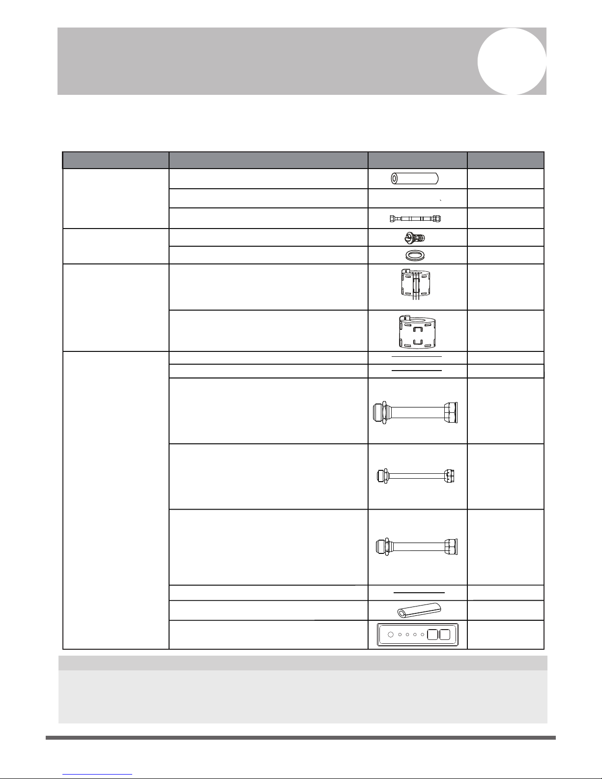
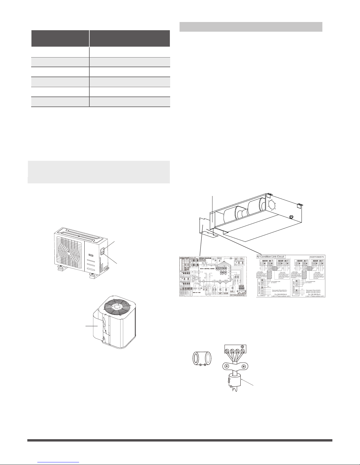
Accessories
1
The air conditioning system comes with the following accessories. Use all of the installation parts
and accessories to install the air conditioner. Improper installation may result in water leakage,
electrical shock and fire, or equipment failure.
There are two types of remote controls: wired and wireless.
Select a remote controller based on customer preferences and requirements and install in an
appropriate place.
Refer to catalogues and technical literature for guidance on selecting a suitable remote controller.
•
Connecting wire for display (2m)
Cord protection rubber ring
QUANTITY
SHAPENAME
Soundproof / insulation sheath
2
1
1
1
Tubing & Fittings
Others
Installation manual
Transfer connector(Φ12.7-Φ15.9)/
Φ0.5in-Φ0.63in
( )(Packed with the indoor unit )
NOTE: Pipe size may dier from appliance to
appliance. To meet dierent pipe size requirements,
sometimes the pipe connections need a transfer
connector installed on the outdoor unit .
Transfer connector(Φ6.35-Φ9.52)/
Φ0.25in-Φ0.375in
( )(Packed with the indoor unit)
NOTE: Pipe size may dier from appliance to
appliance. To meet dierent pipe size requirements,
sometimes the pipe connections need a transfer
connector installed on the outdoor unit .
Transfer connector(Φ9.52-Φ12.7)/
Φ0.375in-Φ0.5in
( ) (Packed with the indoor unit,
used for multi-type models only )
NOTE: Pipe size may dier from appliance to
appliance. To meet dierent pipe size requirements,
sometimes the pipe connections need a transfer
connector installed on the outdoor unit .
1
Owner‘s manual
Drain joint (some models)
Seal ring (some models)
Drainpipe Fittings
(for cooling & heating)
Seal sponge (some models)
EMC Magnetic Ring
(some models)
Magnetic ring
(wrap the electric wires S1 & S2 ( P & Q & E )
around the magnetic ring twice)
Magnetic ring
(Hitch on the connective cable between the indoor
unit and outdoor unit after installation.)
1
1
Orice (some models)
1
1
(on some models)
1
(on some models)
1
(on some models)
1(on some models)
1(on some models)
1
S1&S2(P&Q&E)
Display panel
*Just for testing purposes only
1(on some modelsKJR-120G,KJR-120H)

Page 5
Safety Precautions
2
Read Safety Precautions Before Installation
Incorrect installation due to ignoring instructions can cause serious damage or injury.
The seriousness of potential damage or injuries is classified as either a WARNING or CAUTION.
Failure to observe a warning may result in death. The appliance must be installed in
accordance with national regulations.
Failure to observe a caution may result in injury or equipment damage.
WARNING
CAUTION
WARNING
• Carefully read the Safety Precautions before installation.
• In certain functional environments, such as kitchens, server rooms, etc., the use of specially
designed air-conditioning units is highly recommended.
• Only trained and certified technicians should install, repair and service this air
conditioning unit.
Improper installation may result in electrical shock, short circuit, leaks, fire or other damage to
the equipment and personal property.
• Strictly follow the installation instructions set forth in this manual.
Improper installation may result in electrical shock, short circuit, leaks, fire or other damage to
the equipment.
• Before you install the unit, consider strong winds, typhoons and earthquakes that might aect
your unit and locate it accordingly. Failure to do so could cause the equipment to fail.
• After installation, ensure there are no refrigerant leaks and that the unit is operating properly.
Refrigerant is both toxic and flammable and poses a serious health and safety risk.
Note about Fluorinated Gases
1.
This air-conditioning unit contains fluorinated gases. For specific information on the type of gas
and the amount, please refer to the relevant label on the unit itself.
2.
Installation, service, maintenance and repair of this unit must be performed by a certified
technician.
Product uninstallation and recycling must be performed by a certified technician.3.
If the system has a leak-detection system installed, it must be checked for leaks at least every 12
months.
5.
4.
When the unit is checked for leaks, proper record-keeping of all checks is strongly recommended.

Page 6
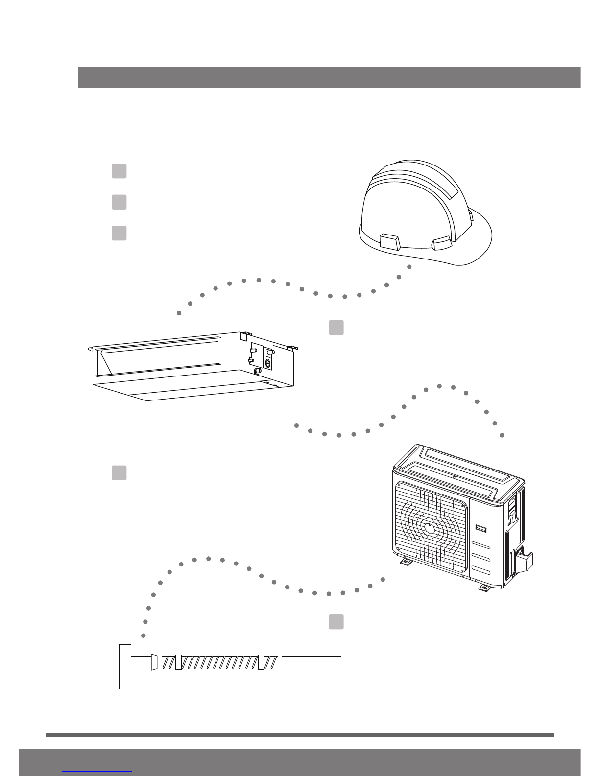
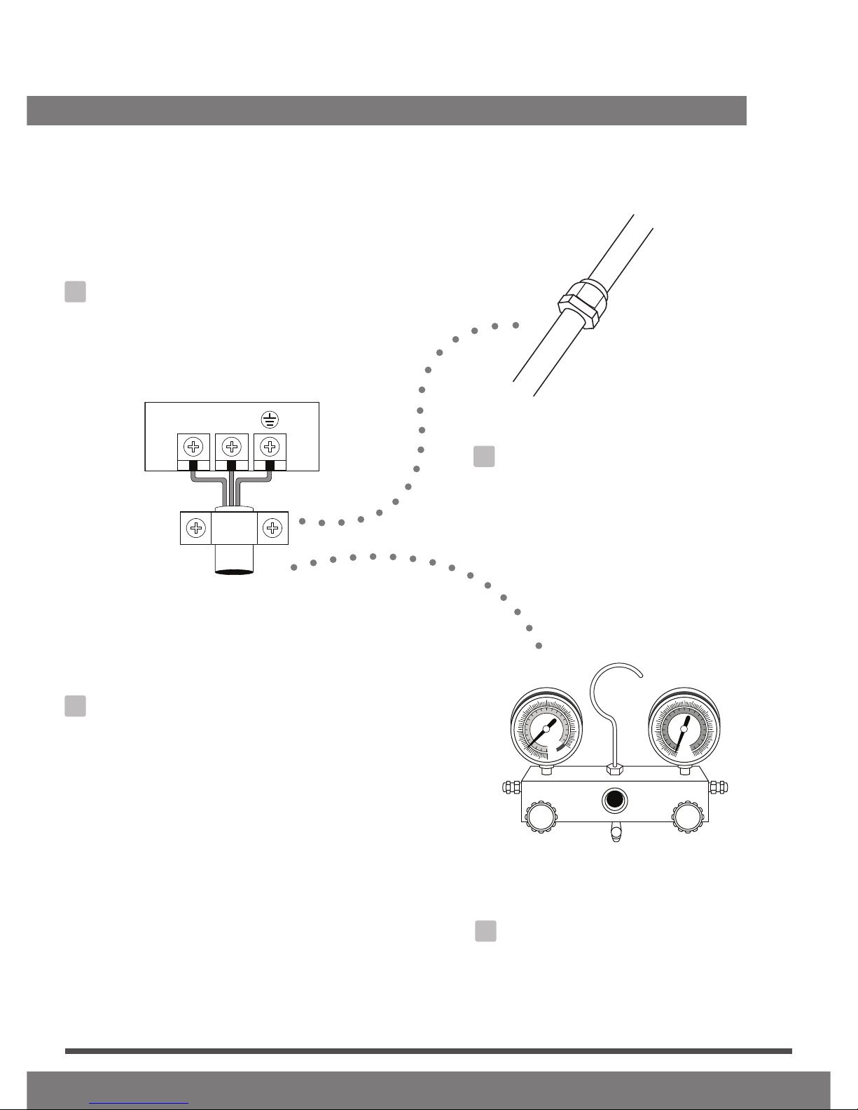
Installation Overview
3
LN
1
2
3
4
5
MC MC
6
7
Install the indoor unit
(Page 8)
INSTALLATION ORDER
Install the outdoor unit
(Page 13)
Install the drainpipe
(Page 15)
Evacuate the refrigeration system
(Page 28)
Connect the wires
(Page 23)
Connect the refrigerant pipes
(Page 18
Perform a test run
(Page 30)
Page 7
Indoor Unit Installation
4
Indoor Unit Parts
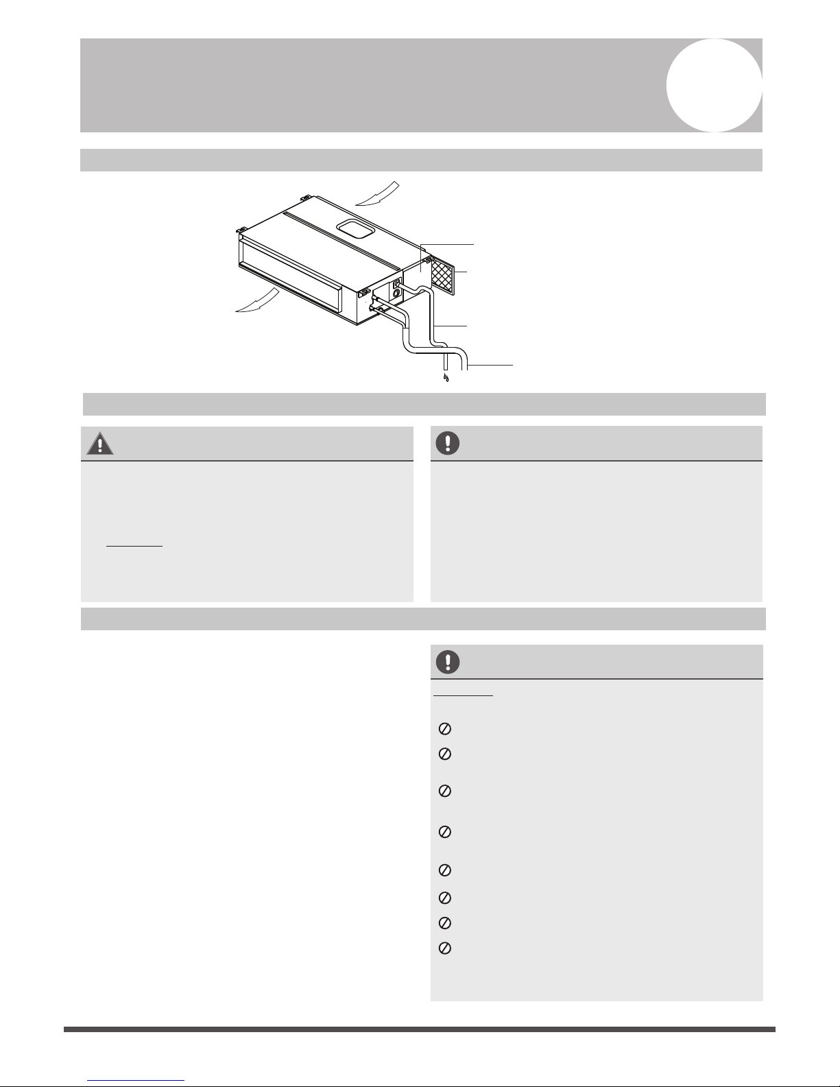
Fig. 4.1
WARNING
• Securely install the indoor unit on a structure
that can sustain its weight. If the structure is
too weak, the unit may fall causing personal
injury, unit and property damage or death.
• DO NOT install the indoor unit in the
bathroom or laundry room as excessive
moisture can short the unit and corrode the
wiring.
CAUTION
• Install the indoor and outdoor units, cables
and wires at least 1m (3.2’) from televisions
or radios to prevent static or image
distortion. Depending on the appliances, a
1m (3.2’) distance may not be sufficient.
• If the indoor unit is installed on a metal
part of the building, it must be electrically
grounded.
Indoor Unit Installation Instructions
Step 1: Select installation location
The indoor unit should be installed in a location
that meets the following requirements:
o Enough room exists for installation and
maintenance.
o Enough room exists for the connecting pipe
and drainpipe.
o The ceiling is horizontal and its structure can
sustain the weight of the indoor unit.
o The air inlet and outlet are not impeded.
o The airflow can fill the entire room.
o There is no direct radiation from heaters.
CAUTION
DO NOT install the unit in the following
locations:
In areas with oil drilling or fracking
In coastal areas with high salt content in the
air
In areas with caustic gases in the air, such as
near hot springs
In areas with power fluctuations, such as
factories
In enclosed spaces, such as cabinets
In areas with strong electromagnetic waves
In areas that store flammable materials or gas
In rooms with high humidity, such as
bathrooms or laundry rooms
Air outlet
Air inlet
Air filter(on some models)
Drain hose
Electric control cabinet
Refrigerant connecting pipe
√
√
√
√
√
√
Safety Precautions
o
√
It is embeded installation.
Models with a cooling capacity of 9000Btu to
18000Btu only apply to one room.
o
√

Page 8
Air outlet
Air inlet
Step 2: Hang indoor unit.
1.
Maintenance space
Installation place
Left
side
Right
side
Strong and durable ceiling
Indoor unit
>4in(10cm) >11.8in(30cm)
>0.8in(2cm)
>0.8in(2cm)
>11.8in(30cm)
> 8.2in(250cm)
Floor
Service access Ceiling
(When no ceiling)
B
Fig. 4.2
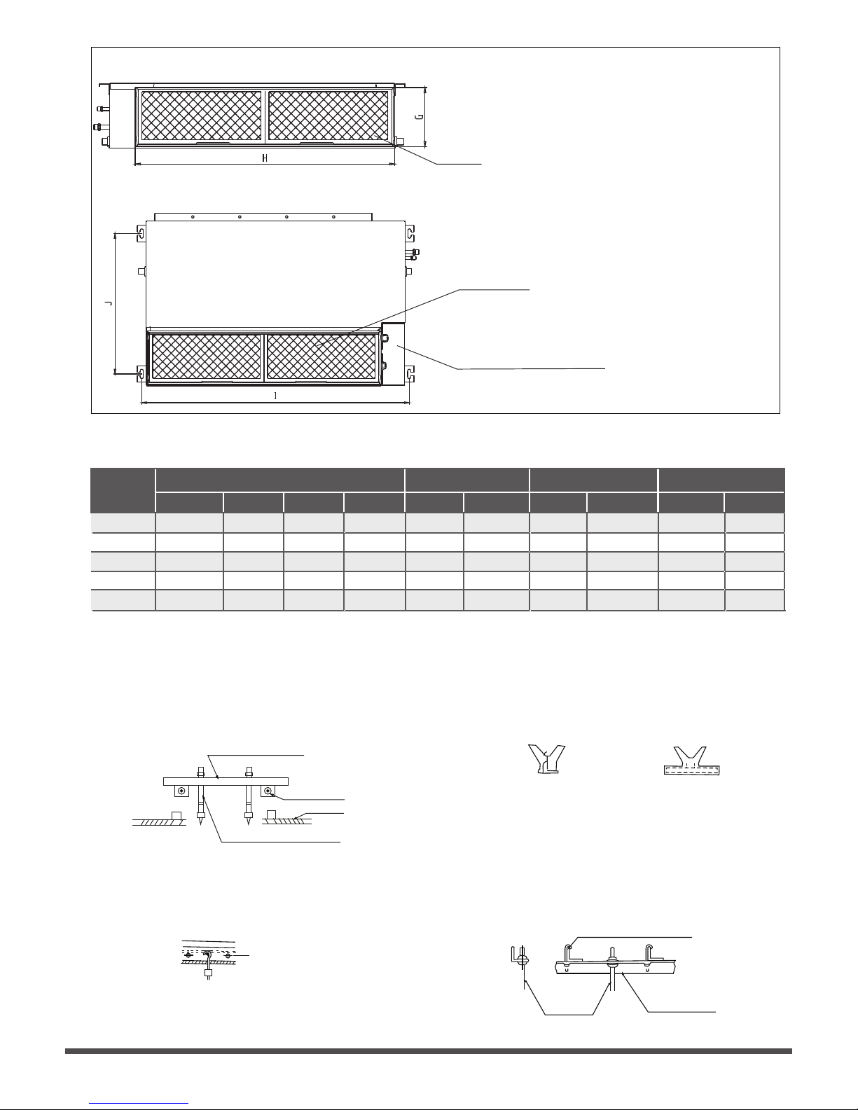
Please refer to the following diagrams to locate the four positioning screw bolt holes on the
ceiling. Be sure to mark the paces where you will drill ceiling hook holes.
Air outlet dimensions
>
7.9
in
(20cm)
11.8in
23.6inx23.6in (60cmx60cm)
checking orifice
> (30cm)
Page 9
Fig. 4.3
Air lter
Descending ventilation opening and mounted hook
Air lter
Electric control box
Table.4-1
MODEL
(Btu/h)
Outline dimension
A B C
air outlet opening size
D E F
air return opening size
(unit: mm/inch)
Size of mounted lug
I
J
G
H
18K 210/8.3 674/26.5880/34.6
24K 249/9.8 774/30.51100/43.3
30K~36K 249/9.8 774/30.51360/53.5
36K~60K 300/11.8 874/34.41200/47.2
136/5.4 706/27.8600/23.6
175/6.9 926/36.5700/27.6
175/6.9 1186/46.7700/27.6
227/8.9 1044/41.1800/31.5
190/7.5
228/8.9
228/8.9
280/11
920/36.2782/30.8
1140/44.91001/39.4
1400/55.11261/49.6
1240/48.81101/43.3
508/20
598/23.5
598/23.5
697/27.4
9K/12K
200/7.9 506/19.9700/27.6
152/6 537/21.1450/17.7 186/7.3 741/29.2599/23.6
360/14.2
Fig. 4.6
Fig. 4.7
Original concrete bricks
Use an embedding screw bolt, crock, and stick
harness.(See Fig.4.6)
Steel Roof beam structure
Install and use the supporting steel angle.
(See Fig.4.7)
Fig. 4.4
Wood
Place the wood mounting across the roof beam,
then install the hanging screw bolts.(See Fig.4.4)
Wood mounting
Roof beam
Hanging screw bolts
Ceiling
Fig. 4.5
New concrete bricks
Inlay or embed the screw bolts. (See Fig. 4.5)
(Blade shape insertion)
(Slide insertion)
Steel bar
Embedding screw bolt
(Pipe hanging and embedding screw bolt)
Hanging screw bolt
Hanging
bolts
Supporting
steel angle
Air inlet dimensions
Page 10
Fig. 4.10
or more.
Step 3: Duct and accessories installation
NOTE: 1. Do not place the connecting duct
weight on the indoor unit.
2. When connecting the duct, use an
nonammable canvas tie-in to prevent
vibrating.
3. Insulation foam must be wrapped outside the
duct to avoid condensate. An internal duct
underlayer can be added to reduce noise,
if the end-user requires.
1. Install the lter (optional) according to the size
of the air inlet.
5. Refer to the following static pressure guidelines
when installing the indoor unit.
Change the fan motor static pressure
according to external duct static pressure.
2. Install the canvas tie-in between the body and
the duct.
3. The air inlet and air outlet duct should be far
enough apart enough to a avoid air passage
short-circuit.
4.
Connect the duct according to the following
diagram:
Canvas tie-in Canvas tie-in
Air outlet
Isolation booth
Isolation booth
checking orice
Air inlet
Air dust lter
Table.4-2
MODEL
(Btu/h)
Static Pressure
(Pa/in.wg)
0~100/0~0.4
18K
0~160/0~0.64
24K
0~160/0~0.64
30K~36K
0~160/0~0.64
42K~60K
0~50/0~0.2
9K
0~50/0~0.2
12K
Cut o the roof beam.
Strengthen the point at which the cut
was made. Consolidate the roof beam.
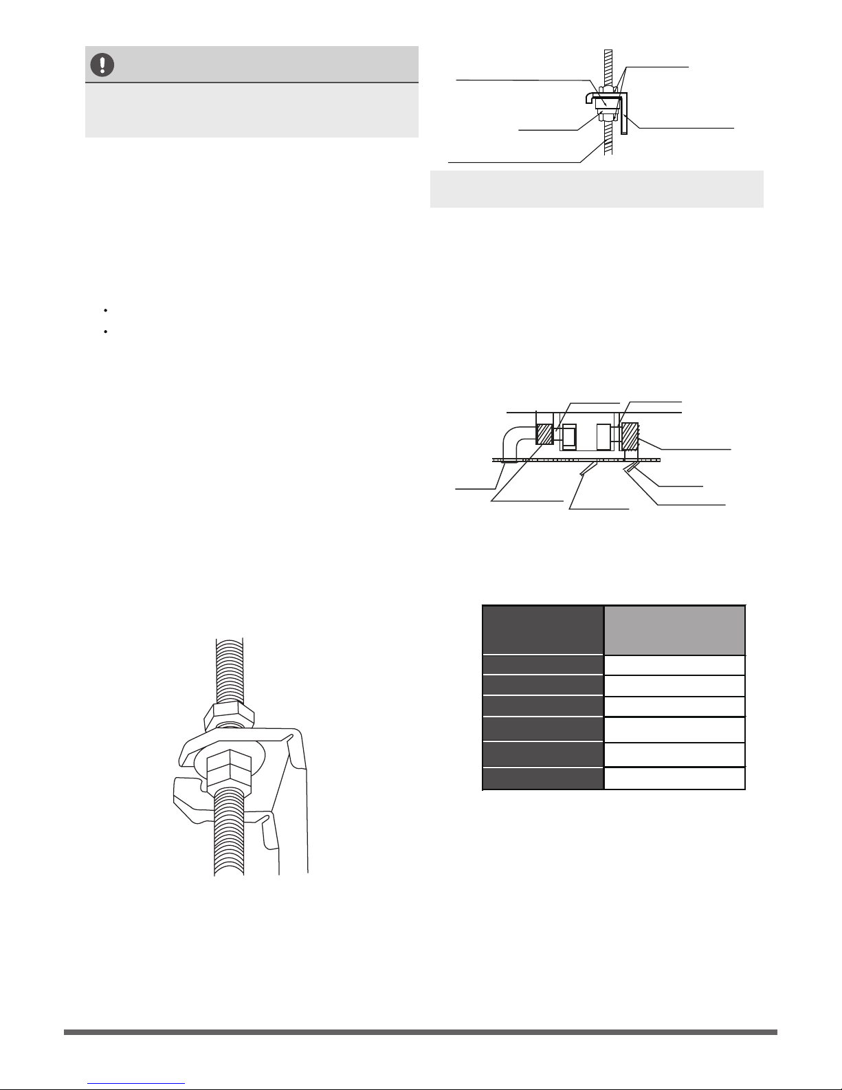
Fig. 4.9
Screw nut
Washer
Hanging screw bolt
Overhang part
Shockproof cushion
NOTE:
Conrm the minimum drain tilt is 1/100
CAUTION
The unit body must be completely aligned with
the hole. Ensure that the unit and the hole are
the same size before moving on.
2.
Install and t pipes and wires after you have
nished installing the main body.When
choosing where to start, determine the
direction of the pipes to be drawn out.
Especially in cases where there is a ceiling
involved, align the refrigerant pipes, drain
pipes, and indoor and outdoor lines with their
connection points before mounting the unit.
3.
Install hanging screw bolts.
4. After you select an installation location,align
the refrigerant pipes, drain pipes, as well as
indoor and outdoor wires with their
connection points before mounting the unit.
5.
Drill 4 holes 10cm (4”) deep at the ceiling
hook positions in the internal ceiling. Be sure
to hold the drill at a 90° angle to the ceiling.
6.
Secure the bolt using the washers and nuts
provided.
7.
Install the four suspension bolts.
8. Mount the indoor unit with at least two
people to lift and secure it. Insert suspension
bolts into the unit’s hanging holes. Fasten
them using the washers and nuts provided.
(See Fig. 4.8).
9. Mount the indoor unit onto the hanging
screw bolts with a block. Position the
indoor unit at using a level indicator to
prevent leaks. (See Fig. 4.9).
Fig. 4.8
Page 11
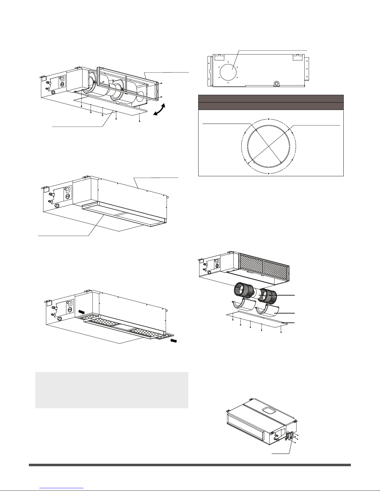
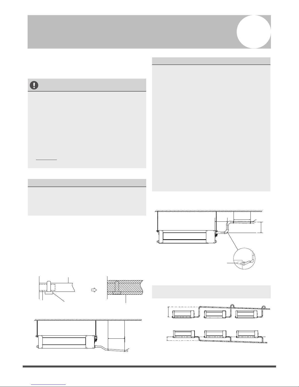
Step 4: Adjust the air inlet direction
(from rear side to under-side).
1. Take o the ventilation panel and ange.
2. Change the mounting positions of the
ventilation panel and air return ange.
Air return ange
Ventilation panel
3. When installing the lter mesh, t it into the
ange as illustrated in the following gure.
NOTE:
All the gures in this manual are for
demonstration purposes only. The air conditioner
you have purchased may be slightly dierent in
design, though similar in shape.
Step 5: Fresh air duct installation
Dimension :
Duct joint for fresh air
Ø125mm(4.92”)
Ø160mm(6.3”)
MODLE
18-60
Fig. 4.14
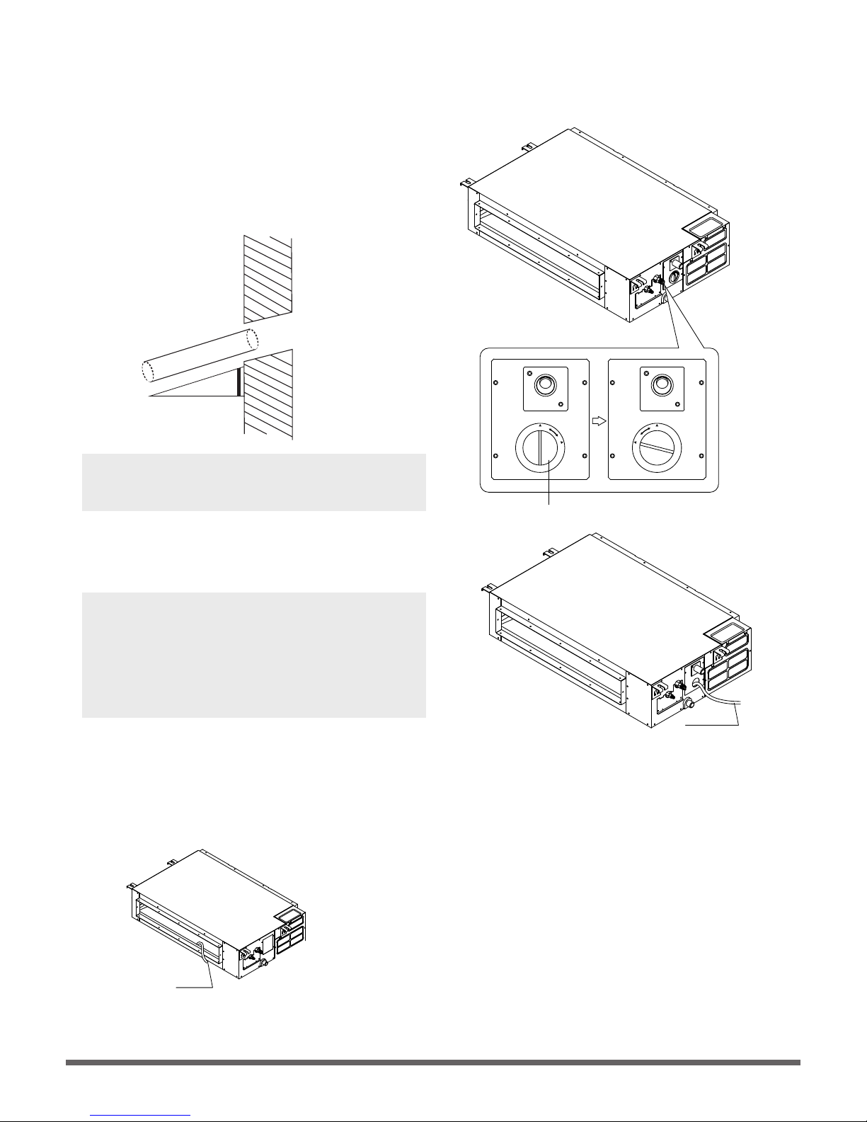
Step 6: Motor and drain pump maintenance
Motor maintain:
Take o the ventilated panel.
Take o the blower housing.
Take o the motor.
1.
2.
3.
(the rear ventilated panel is used as an example)
Motor
Blower housing
Ventilated panel
Pump maintainance:
Remove four screws from the drain pump.
Unplug the pump power supply and water
level switch cable.
Detach the pump.
1.
2.
3.
Pump
Fig. 4.11
Fig. 4.12
Fig. 4.13
Fig. 4.15
Fig. 4.16
Air return ange
Ventilation panel
Page 12
Outdoor Unit Installation
Outdoor Unit Installation Instructions
Step 1: Select installation location.
The outdoor unit should be installed in the
location that meets the following requirements:
o Place the outdoor unit as close to the indoor
unit as possible.
o Ensure that there is enough room for
installation and maintenance.
o The air inlet and outlet must not be
obstructed or exposed to strong wind.
o Ensure the location of the unit will not be
subject to snowdrifts, accumulation of leaves
or other seasonal debris. If possible, provide
an awning for the unit. Ensure the awning
does not obstruct airflow.
o The installation area must be dry and well
ventilated.
o There must be enough room to install the
connecting pipes and cables and to access
them for maintenance.
o The area must be free of combustible gases
and chemicals.
o The pipe length between the outdoor and
indoor unit may not exceed the maximum
allowable pipe length.
o If possible, DO NOT install the unit where it
is exposed to direct sunlight.
o If possible, make sure the unit is located far
away from your neighbors’ property so that
the noise from the unit will not disturb them.
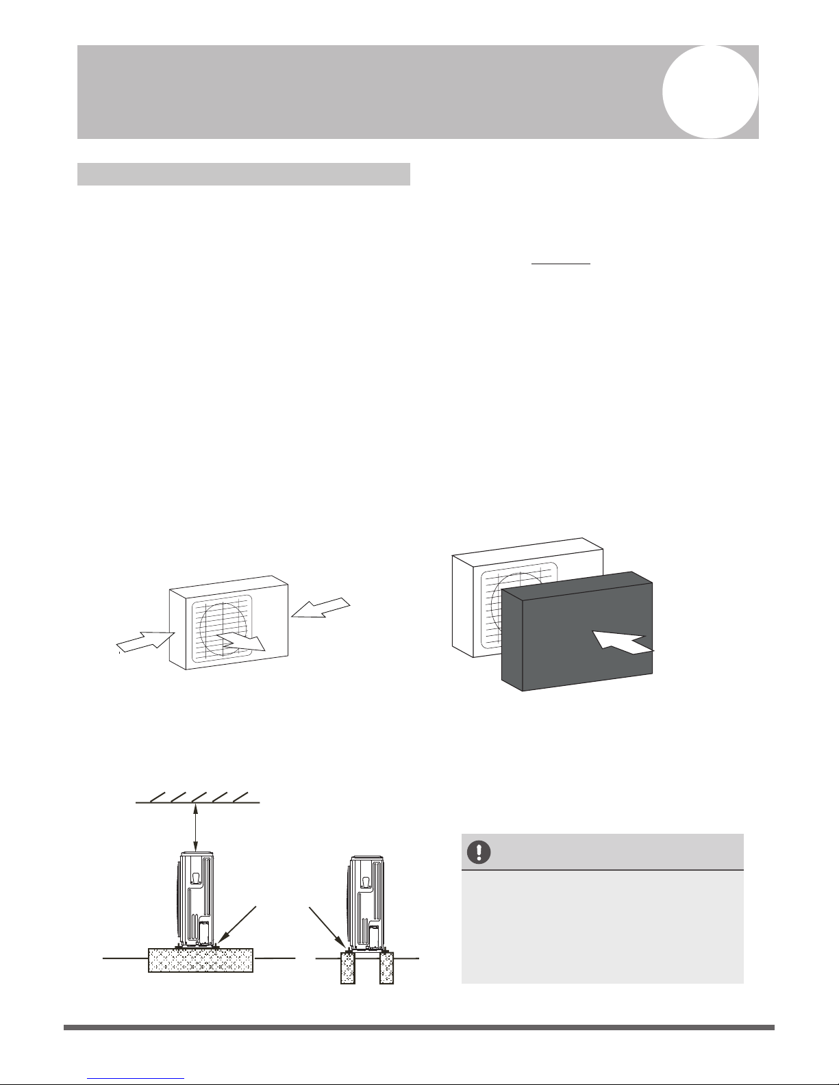
o If the location is exposed to strong winds (for
example: near a seaside), the unit must be
placed against the wall to shelter it from the
wind. If necessary, use an awning.
(See Fig. 5.1 & 5.2)
o Install the indoor and outdoor units, cables
and wires at least 1 meter from televisions or
radios to prevent static or image distortion.
Depending on the radio waves, a 1 meter
distance may not be enough to eliminate all
interference.
Strong wind
Strong wind
Strong wind
Fig. 5.1 Fig. 5.2
Step 2: Install outdoor unit.
Fix the outdoor unit with anchor bolts (M10)
>60cm / 23.6”
Fix with bolts
CAUTION
•
Be sure to remove any obstacles that
may block air circulation.
• Make sure you refer to Length
Specifications to ensure there is
enough room for installation and
maintenance.
Fig. 5.3
5
√
√
√
√
√
√
√
√
√
√
√
√
>120cm / 47”
Air Outlet
(Wall or obstacle)
H
D
W
>30cm / 11.8”
Air inlet
Air inlet
Air inlet
Air inlet
(Wall or obstacle)
>30cm / 11.8”
>30cm / 11.8”
>30cm / 11.8”
Table 5.1: Length Specifications of Split
Type Outdoor Unit (unit: mm/inch)
Table 5.2: Length Specifications of Vertical
Discharge Outdoor Unit (unit: mm/inch)
MODEL
DIMENSIONS
W H D
18 633/25 554/21.8554/21.8
24 633/25 554/21.8554/21.8
36 759/29.8 554/21.8554/21.8
36 633/25 600/23.6600/23.6
48 759/29.8 710/28710/28
60 843/33 710/28710/28
Split Type Outdoor Unit
(Refer to Fig 5.4, 5.5, 5.6, 5.10 and Table 5.1)
Vertical Discharge Type Outdoor Unit
(Refer to Fig 5.7, 5.8, 5.9 and Table 5.2)
Fig. 5.7
Fig. 5.8
Fig. 5.9
Fig. 5.6
Fig. 5.5
A
B
D
W
H
W
H
Fig. 5.4
Outdoor Unit Dimensions
W x H x D
Mounting Dimensions
Distance A Distance B
770x555x300 (30.3x21.85x11.81) 487 (19.2) 298 (11.73)
810x558x310 (31.9x22x12.2) 549 (21.6) 325 (12.8)
845x700x320 (33.27x27.5x12.6) 560 (22) 335 (13.2)
900x860x315 (35.4x33.85x12.4) 590 (23.2) 333 (13.1)
945x810x395 (37.2x31.9x15.55) 640 (25.2) 405 (15.95)
990x965x345 (38.98x38x13.58) 624 (24.58) 366 (14.4)
946x810x420 (37.24x31.9x16.53) 673 (26.5)
403 (15.87)
946x810x410 (37.24x31.9x16.14) 673 (26.5)
403 (15.87)
952x1333x410 (37.5x52.5x16.14) 634 (24.96)
404 (15.9)
952x1333x415 (37.5x52.5x16.34) 634 (24.96)
404 (15.9)
845x702x363 (33.27x27.6x14.3)
540 (21.26)
350 (13.8)
938x1369x392 (36.93x53.9x15.43) 634 (24.96) 404 (15.9)
900x1170x350 (35.4x46x13.8) 590 (23.2) 378 (14.88)
800x554x333 (31.5x21.8x13.1) 514 (20.24) 340 (13.39)

Page 13
>120cm / 47”
Air Outlet
(Wall or obstacle)
H
D
W
>30cm / 11.8”
Air inlet
Air inlet
Air inlet
Air inlet
(Wall or obstacle)
>30cm / 11.8”
>30cm / 11.8”
>30cm / 11.8”
Table 5.1: Length Specifications of Split
Type Outdoor Unit (unit: mm/inch)
Table 5.2: Length Specifications of Vertical
Discharge Outdoor Unit (unit: mm/inch)
MODEL
DIMENSIONS
W H D
18 633/25 554/21.8554/21.8
24 633/25 554/21.8554/21.8
36 759/29.8 554/21.8554/21.8
36 633/25 600/23.6600/23.6
48 759/29.8 710/28710/28
60 843/33 710/28710/28
Split Type Outdoor Unit
(Refer to Fig 5.4, 5.5, 5.6, 5.10 and Table 5.1)
Vertical Discharge Type Outdoor Unit
(Refer to Fig 5.7, 5.8, 5.9 and Table 5.2)
Fig. 5.7
Fig. 5.8
Fig. 5.9
Fig. 5.6
Fig. 5.5
A
B
D
W
H
W
H
Fig. 5.4
Outdoor Unit Dimensions
W x H x D
Mounting Dimensions
Distance A Distance B
770x555x300 (30.3x21.85x11.81) 487 (19.2) 298 (11.73)
810x558x310 (31.9x22x12.2) 549 (21.6) 325 (12.8)
845x700x320 (33.27x27.5x12.6) 560 (22) 335 (13.2)
900x860x315 (35.4x33.85x12.4) 590 (23.2) 333 (13.1)
945x810x395 (37.2x31.9x15.55) 640 (25.2) 405 (15.95)
990x965x345 (38.98x38x13.58) 624 (24.58) 366 (14.4)
946x810x420 (37.24x31.9x16.53) 673 (26.5)
403 (15.87)
946x810x410 (37.24x31.9x16.14) 673 (26.5)
403 (15.87)
952x1333x410 (37.5x52.5x16.14) 634 (24.96)
404 (15.9)
952x1333x415 (37.5x52.5x16.34) 634 (24.96)
404 (15.9)
845x702x363 (33.27x27.6x14.3)
540 (21.26)
350 (13.8)
938x1369x392 (36.93x53.9x15.43) 634 (24.96) 404 (15.9)
900x1170x350 (35.4x46x13.8) 590 (23.2) 378 (14.88)
800x554x333 (31.5x21.8x13.1) 514 (20.24) 340 (13.39)
Page 14
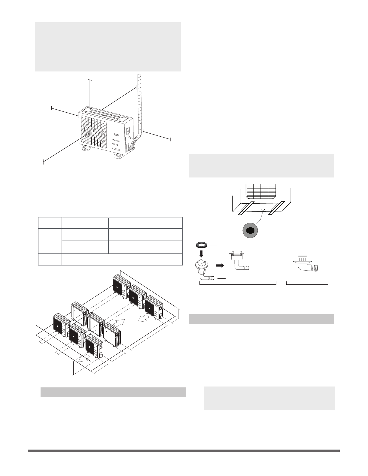
NOTE: The minimum distance between the
outdoor unit and walls described in the
installation guide does not apply to airtight
rooms. Be sure to keep the unit unobstructed
in at least two of the three directions (M, N, P)
(See Fig. 5.10)
M
N
P
30 cm / 11.8” from back wall
60 cm / 23.6” on right
evoba ”6.32 / mc 06
30 cm / 11.8” on left
200 cm / 78” in front
Fig. 5.10
Fig. 5.11
NOTE: Make sure the water drains to a safe
location wher
e it will not cause water damage
or a slipping hazard.
Seal
Drain joint
(A) (B)
Base pan hole of
outdoor unit
Seal
Fig. 5.12
llaW nI eloH gnillirD nO setoN
You must drill a hole in the wall for the
refrigerant piping, and the signal cable that will
connect the indoor and outdoor units.
1. Determine the location of the wall hole
based on the location of the outdoor unit.
2. Using a 65-mm (2.5”) core drill, drill a hole
in the wall.
NOTE: When drilling the wall hole, make
sure to avoid wires, plumbing, and other
sensitive components.
3. Place the protective wall cuff in the hole.
This protects the edges of the hole and will
help seal it when you finish the installation
process.
Fig. 5.11
L
H
300 cm / 118” or more
A
60 cm / 23.6”
or more
150 cm / 59”
or more
25 cm / 9.8”
or more
25 cm / 9.8”
or more
Rows of series installation
L ≤ H
L ≤ 1/2H
L A
25 cm / 9.8” or more
1/2H < L ≤ H
30 cm / 11.8” or more
L > H
Can not be installed
Table 5.3 The relations between H, A and L
are as follows.
Drain Joint Installation
If the drain joint comes with a rubber seal
(see Fig. 5.12 - A ), do the following:
1. Fit the rubber seal on the end of the drain joint
that will connect to the outdoor unit.
2. Insert the drain joint into the hole in the base
pan of the unit.
3. Rotate the drain joint 90° until it clicks in place
facing the front of the unit.
4.
1.
2.
Connect a drain hose extension (not included)
to the drain joint to redirect water from the
unit during heating mode.
If the drain joint doesn’t come with a rubber
seal (see Fig. 5.12 - B ), do the following:
Insert the drain joint into the hole in the base
pan of the unit. The drain joint will click in
place.
Connect a drain hose extension (not included)
to the drain joint to redirect water from the
unit during heating mode.
Page 15
Fig. 6.3
(39-59”)
(7.9”)
<20cm
(21.7”)
<55cm
Lean over 1/50
1-1.5m1-1
Drainpipe installation for units with a pump
Ceiling
0 - 75mm
(3”)
NOTE ON DRAINPIPE INSTALLATION
•
When using an extended drainpipe, tighten
the indoor connection with an additional
protection tube. This prevents it from
pulling loose.
• The drainpipe should slope downward at a
gradient of at least 1/100 to prevent water
from flowing back into the air conditioner.
• To prevent the pipe from sagging, space
hanging wires every 1-1.5m (39-59”).
• If the outlet of the drainpipe is higher than
the body’s pump joint, use a lift pipe for
the indoor unit’s exhaust outlet. The lift
pipe must be installed no higher than
55cm (21.7”) from the ceiling board. The
distance between the unit and the lift pipe
must be less than 20cm (7.9”). Incorrect
installation could cause water to flow back
into the unit and flood.
The drainpipe is used to drain water away from
the unit. Improper installation may cause unit
and property damage.
CAUTION
•
Insulate all piping to prevent condensation,
which could lead to water damage.
•
If the drainpipe is bent or installed
incorrectly, water may leak and cause a
water-level switch malfunction.
•
In HEAT mode, the outdoor unit will
discharge water. Ensure that the drain hose
is placed in an appropriate area to avoid
water damage and slippage.
•
DO NOT pull the drainpipe forcefully. This
could disconnect it.
NOTE ON PURCHASING PIPES
This installation requires a polyethylene tube
(outside diameter = 3.7-3.9cm, inside diameter
= 3.2cm), which can be obtained at your local
hardware store or dealer.
Indoor Drainpipe Installation
Install the drainpipe as illustrated in Figure 6.2.
1.
2.
Drainpipe
connecting port
Drain hose
Pipe clasp
Insulation
Fig. 6.1
Drainpipe Installation
Fig. 6.2
6
Cover the drainpipe with heat insulation to
prevent condensation and leakage.
Attach the mouth of the drain hose to the
unit’s outlet pipe. Sheath the mouth of the
hose and clip it firmly with a pipe clasp.
(Fig 6.1)
NOTE: When connecting multiple drainpipes,
install the pipes as illustrated in Fig 6.4.
(39-59”)
1-1.5m1-1
Lean over 1/50
Ceiling
• To prevent air bubbles, keep the drain hose
level or slightly tiled up (<75mm / 3”).
0-53cm
(20.8”)
≥10cm
(4”)
Fig. 6.4
Page 16
Drainage test
Check whether the drainpipe is unhindered.
This test should be performed on newly built
houses before the ceiling is paved.
Units with a pump.
Units without a pump.
1. Remove the test cover.
Fill the water pan with 2 liters of water.
2. Turn on the unit in COOLING mode. You will
hear the drain pump.Check whether the
water is discharged properly (a 1-minute lag
is possible, depending on the length of the
drain pipe), Check whether water leaks from
the joints.
3. Turn off the air conditioner and put the cap
back on.
3. Using a 65-mm (2.5”) core drill, drill a hole in
the wall. Make sure that the hole is drilled at
a slight downward angle, so that the outdoor
end of the hole is lower than the indoor end
by about 12mm (0.5”). This will ensure proper
water drainage (See Fig. 6.5). Place the
protective wall cuff in the hole. This protects
the edges of the hole and will help seal it
once you finish installation.
Wall
Indoor
Outdoor
≈ 12mm / 0.5 inch
Fig. 6.5
NOTE: When drilling the hole, make sure to
avoid wires, plumbing, and other sensitive
components.
4.
Pass the drain hose through the wall hole.
Make sure the water drains to a safe location
where it will not cause water damage or a
slipping hazard.
NOTE: The drainpipe outlet should be at least
5cm (1.9”) above the ground. If it touches the
ground, the unit may become blocked and
malfunction. If you discharge the water directly
into a sewer, make sure that the drain has a U
or S pipe to catch odors that might otherwise
come back into the house.
Test cap
Fig.6.7
Fig.6.8
C
L
O
S
E
D
O
P
E
N
C
L
O
S
E
D
O
P
E
N
Stow tube
Fig.6.6
Stow tube
Fill the water pan with 2 liters of water.
Check that the drainpipe is unhindered.
Page 17
Refrigerant Piping Connection
Safety Precautions
WARNING
• All field piping must be completed by a
licensed technician and must comply with
the local and national regulations.
• When the air conditioner is installed in a
small room, measures must be taken to
prevent the refrigerant concentration in
the room from exceeding the safety limit
in the event of refrigerant leakage. If the
refrigerant leaks and its concentration
exceeds its proper limit, hazards due to
lack of oxygen may result.
• When installing the refrigeration system,
ensure that air, dust, moisture or foreign
substances do not enter the refrigerant
circuit. Contamination in the system may
cause poor operating capacity, high
pressure in the refrigeration cycle,
explosion or injury.
• Ventilate the area immediately if there is
refrigerant leakage during the installation.
Leaked refrigerant gas is both toxic and
flammable. Ensure there is no refrigerant
leakage after completing the installation
work.
Notes On Pipe Length and Elevation
Ensure that the length of the refrigerant pipe, the
number of bends, and the drop height between
the indoor and outdoor units meets the
requirements shown in Table 7.1:
Table 7.1: The Maximum Length And Drop
Height Based on Models. (Unit: m/ft.)
Type of model Capacity
(Btu/h)
Length of
piping
Maximum drop
height
North America,
Australia and the
eu frequency
conversion Split
Type
<15K 25/82 10/32.8
≥15K - <24K 30/98.4 20/65.6
≥24K - <36K 50/164 25/82
≥36K - ≤60K 65/213 30/98.4
Other Split Type
12K 15/49 8/26
18K-24K 25/82 15/49
30K-36K 30/98.4 20/65.6
42K-60K 50/164 30/98.4
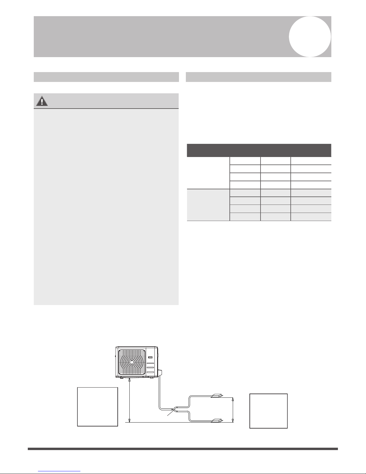
Refrigerant Piping with Twin Indoor Units
When installing multiple indoor units with a single outdoor unit, ensure that the length of the
refrigerant pipe and the drop height between the indoor and outdoor units meet the requirements
illustrated in the following diagram:
L
L1
L2
H2
The line branch pipe
Indoor unit
Outdoor unit
H1
Indoor unit
The drop height
between two
indoor units
must be less
than or equal to
50cm (19.6”)
The drop height
between indoor
unit
and outdoor unit
must be less than
or equal to 20m
(65.6’)
Fig. 7.1
7
Page 18
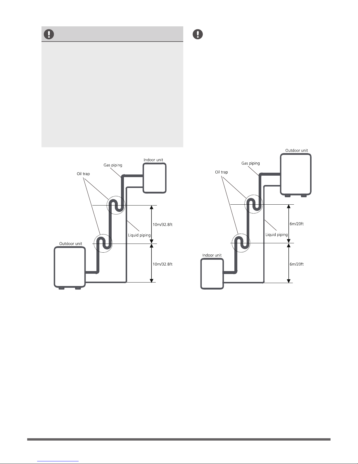
Oil traps
CAUTION
•
If the indoor unit is installed higher than the
outdoor unit:
An oil trap should be installed every 10m
(32.8ft) of vertical suction line riser.
(See Fig. 7.2)
-If oil flows back into the outdoor unit’s
compressor, this might cause liquid
compression or deterioration of oil return.
Oil traps in the rising gas piping can prevent
this.
CAUTION
Fig. 7.2
The indoor unit is installed higher than the
outdoor unit
If the outdoor unit is installed higher than the
indoor unit:
-It is recommended that vertical suction risers
not be upsized. Proper oil return to the
compressor should be maintained with suction
gas velocity. If velocities drop below7.62m/s
(1500fpm (feet per minute)), oil return will be
decreased. An oil trap should be installed every
6m(20ft) of vertical suction line riser.
(See Fig. 7.3)
Fig. 7.3
The outdoor unit is installed higher than the
indoor unit
Page 19
Pipe
Reamer
Point dow n
Fig. 7.5
Table 7.2
Piping
length
Total piping length
Permitted length
18K+18K 30m/98’ L+Max
(L1, L2)
24K+24K
30K+30K
50m/164’
(farthest distance from
the line pipe branch)
15m/49’ L1, L2
(farthest distance from
the line pipe branch)
10m/32.8’ L1-L2
Drop
height
Drop height between
indoor and outdoor unit
20m/65.6’ H1
Drop height between
two indoor units
0.5m/1.6’ H2
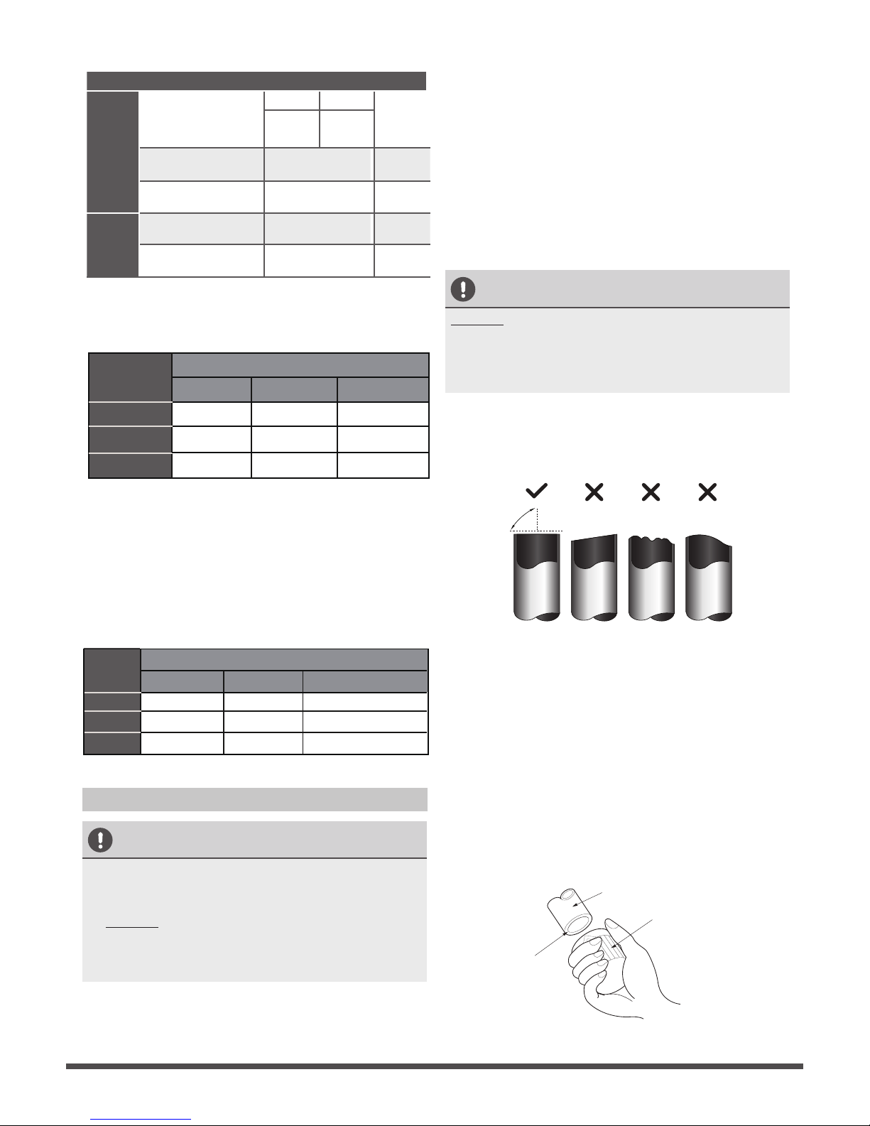
CAUTION
DO NOT deform pipe while cutting. Be extra
careful not to damage, dent, or deform the pipe
while cutting. This will drastically reduce the
heating efficiency of the unit.
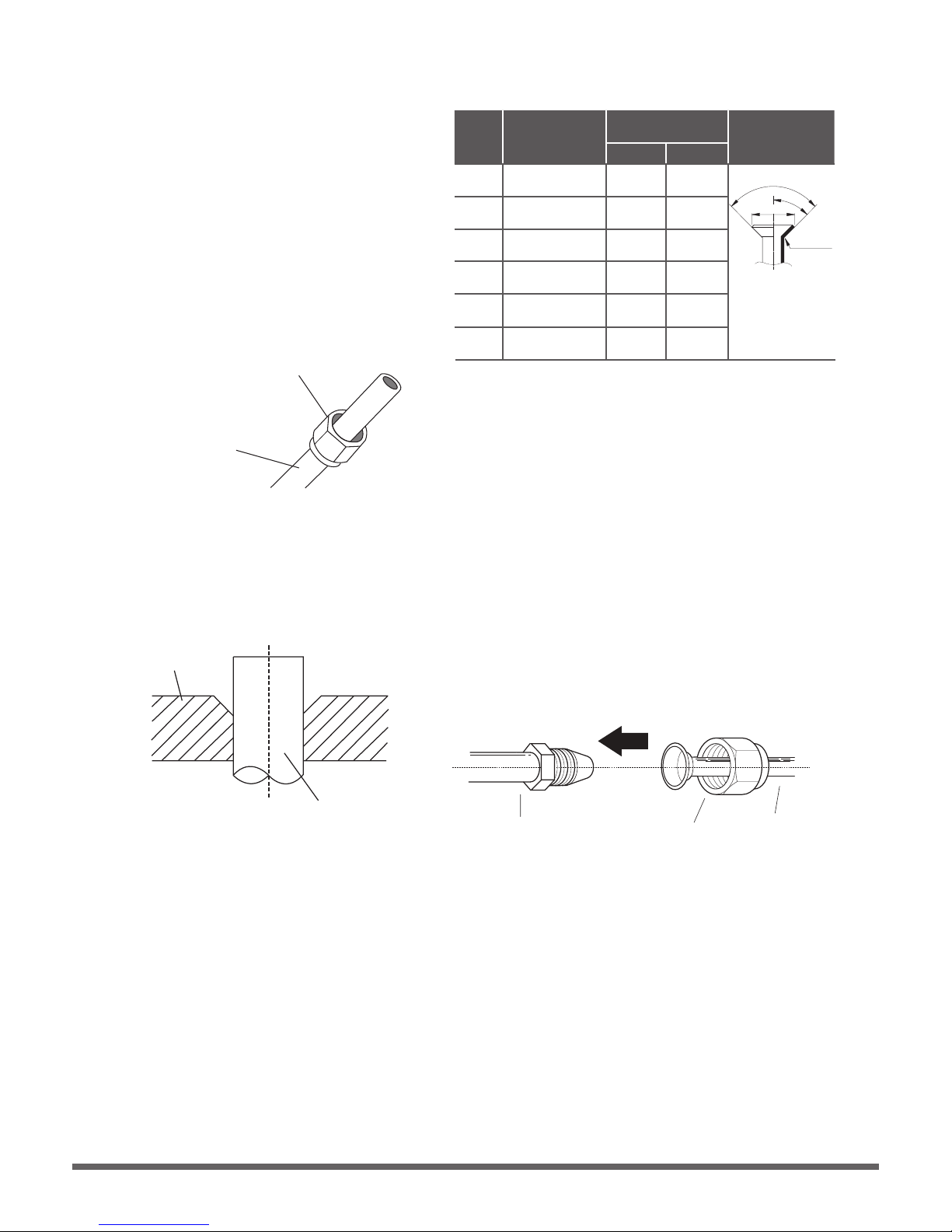
1. Make sure that the pipe is cut at a perfect
90° angle. Refer to Fig. 7.4 for examples
of bad cuts
Oblique
Rough
Warped
90°
Fig. 7.4
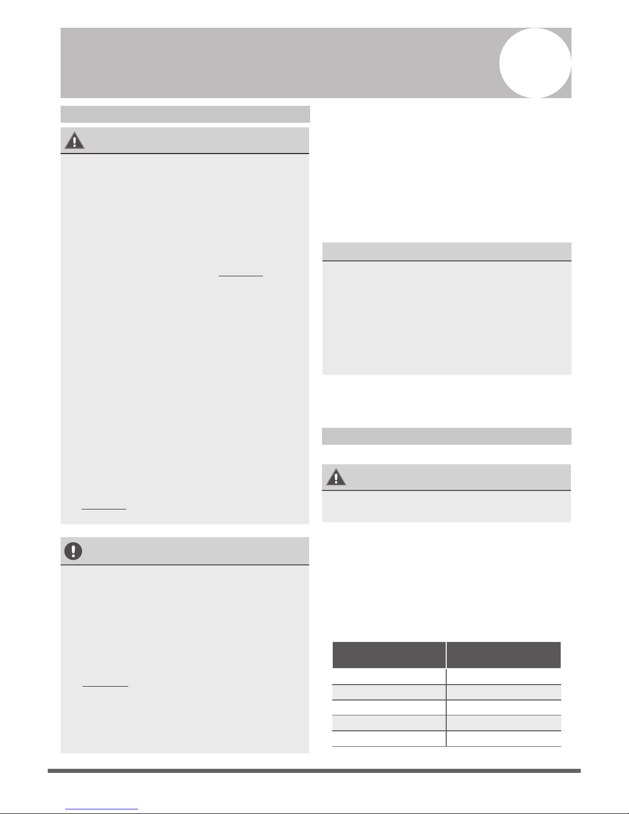
Step2: Remove burrs.
Burrs can aect the air-tight seal of refrigerant
piping connection. They must be completely
removed.
1. Hold the pipe at a downward angle to
prevent burrs from falling into the pipe.
2. Using a reamer or deburring tool, remove
all burrs from the cut section of the pipe.
Size of joint pipes for indoor unit
Gas side
Capacity
of indoor
unit (A)
Size of main pipe(mm)
Liquid side
Φ12.7(0.5”)
Φ15.9(0.626
”)
Φ15.9(0.626
”)
Φ6.35(0.25
”)
Φ9.5(0.375
”)
Φ9.5(0.375
”)
18K
24K
30K
Table 7.3
Size of joint pipes for 410A indoor unit
CE-FQZHN-01C
CE-FQZHN-01C
CE-FQZHN-01C
Available
branching pipe
Size of joint pipes for outdoor unit
Base on the following tables, select the diameters
of the outdoor unit connective pipes. In case of the
main accessory pipe larger than the main pipe, take
the larger one for the selection.
Model
Gas side Liquid side
Φ15.9(0.626”)
Φ15.9(0.626
”)
Φ15.9(0.626
”)
Φ9.5(0.375
”)
Φ9.5(0.375
”)
Φ9.5(0.375
”)
the size of main pipe(mm)
36K
48K
60K
Table 7.4
Size of joint pipes for 410A outdoor unit
The 1st branching pipe
CE-FQZHN-01C
CE-FQZHN-01C
CE-FQZHN-01C
Step1: Cut pipes
When preparing refrigerant pipes, take extra
care to cut and flare them properly. This will
ensure efficient operation and minimize the
need for future maintenance.
1. Measure the distance between the indoor
and outdoor units.
2. Using a pipe cutter, cut the pipe a little
longer than the measured distance.
Refrigerant Piping Connection Instructions
CAUTION
• The branching pipe must be installed
horizontally. An angle of more than 10° may
cause malfunction.
• DO NOT install the connecting pipe until both
indoor and outdoor units have been installed.
• Insulate both the gas and liquid piping to
prevent water leakage.
Page 20
TAKE NOTE OF FUSE SPECIFICATIONS
The air conditioner’s printed circuit board(PCB)
is designed with a fuse that provides overcurrent
protection. The specifications of the fuse are
printed on the circuit board, such as:
T5A/250VAC and 10A/250VAC.
Wiring
Safety Precautions
WARNING
• Disconnect the power supply before
working on the unit.
• All wiring must be performed according to
local and national regulations.
• Wiring must be done by a qualified
technician. Improper connections may
cause electrical malfunction, injury, or fire.
•
An i ndependent circuit and single outlet
must be used for this unit. DO NOT plug
another appliance or charger into the
same outlet. If the cannot handle the load
or there is a defect in the wiring, it can
lead to shock, fire, and unit and property
damage.
• Connect the power cable to the terminals
and fasten it with a clamp. An insecure
connection may cause fire.
• Make sure that all wiring is done correctly
and the control board cover is properly
installed. Failure to do so can cause
overheating at the connection points, fire,
and electrical shock.
• Ensure that main power supply connection
is made through a switch that disconnects
all poles, with contact gap of at least 3mm
(0.118”).
• DO NOT modify the length of the power
cord or use an extension cord.
CAUTION
• Connect the outdoor wires before
connecting the indoor wires.
• Make sure you ground the unit. The
grounding wire should be located away
from gas pipes, water pipes, lightning rods,
telephone wires or other grounding wires.
Improper grounding may cause electrical
shock.
• DO NOT connect the unit to the power
source until all wiring and piping is
completed.
• Make sure that you do not cross your
electrical wiring with your signal wiring.
This may cause distortion and interference.
To prevent distortion when the compressor starts
(you can find the unit’s power information on
the rating sticker):
• The unit must be connected to the main
outlet. Normally, the power supply must
have a impedance of 32 ohms.
• No other equipment should be connected
to the same power circuit.
Outdoor Unit Wiring
WARNING
Before performing any electrical or wiring work,
turn off the main power to the system.
1. Prepare the cable for connection
a. You must first choose the right cable size.
Be sure to use H07RN-F cables.
Table 8.1: Minimum Cross-Sectional Area of
Power and Signal Cables in North America
Rated Current of
Appliance (A)
AWG
≤ 7 18
7 - 13 16
13 - 18 14
18 - 25 12
25 - 30 10
8
Page 21
b. Using wire strippers, strip the rubber jacket
from both ends of the signal cable to reveal
approximately 15cm (5.9”) of wire.
c.
Strip the insulation from the ends.
d. Using a wire crimper, crimp u-lugs on the
ends.
NOTE: When connecting the wires, strictly
follow the wiring diagram found inside the
electrical box cover.
2.
Remove the electric cover of the outdoor unit.
If there is no cover on the outdoor unit, take
off the bolts from the maintenance board
and remove the protection board.
(See Fig. 8.1 and 8.2).
Cover
Screw
Fig. 8.1
Protection Board
Fig. 8.2
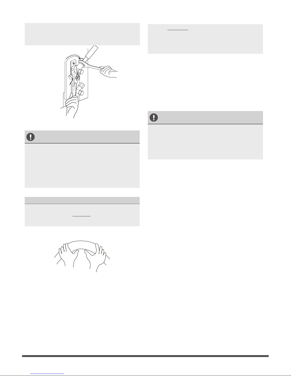
3.
Connect the u-lugs to the terminals
Match the wire colors/labels with the labels
on the terminal block. Firmly screw the u-lug
of each wire to its corresponding terminal.
4. Clamp down the cable with the cable clamp.
5.
Insulate unused wires with electrical tape.Keep
them away from any electrical or metal parts.
6. Reinstall the cover of the electric control box.
Indoor Unit Wiring
1.
Prepare the cable for connection.
a. Using wire strippers, strip the rubber jacket
from both ends of the signal cable to reveal
about 15cm (5.9”) of the wire.
b.
Strip the insulation from the ends of the
wires.
c.
Using a wire crimper, crimp the u-lugs to
the ends of the wires.
2. Remove the cover of the electric control box
on your indoor unit.
3.
Connect the u-lugs to the terminals.
Match the wire colors/labels with the labels
on the terminal block. Firmly screw the
u-lug of each wire to its corresponding
terminal. Refer to the Serial Number and
Wiring Diagram located on the cover of the
electric control box.
Connective wiring diagram
Wiring diagram
Control box
Fig. 8.3
Table 8.2: Other World Regions
Rated Current of
Appliance (A)
Area (mm²)
Nominal Cross-Sectional
≤ 6 0.75
6 - 10 1
10 - 16 1.5
16 - 25 2.5
25- 32 4
32 - 45 6
Fig. 8.4
Magnetic ring
(if supplied and packed with the accessories)
1 2 3
Pass the belt through
the hole of the Magnetic
ring to fix it on the cable
Page 22
Step 3: Flare pipe ends
Proper flaring is essential to achieve an
airtight seal.
1. After removing burrs from cut pipe, seal
the ends with PVC tape to prevent foreign
materials from entering the pipe.
2. Sheath the pipe with insulating material.
3.
Place flare nuts on both ends of pipe.
Make sure they are facing in the right
direction, because you can’t put them on
or change their direction after flaring.
See Fig. 7.6
Flare nut
Copper pipe
Fig. 7.6
4.
Remove PVC tape from ends of pipe when
ready to perform flaring work.
5.
Clamp flare form on the end of the pipe.
The end of the pipe must extend beyond
the flare form.
Flare form
Pipe
Fig. 7.7
6.
Place flaring tool onto the form.
7.
Turn the handle of the flaring tool
clockwise until the pipe is fully flared.
Flare the pipe in accordance with the
dimensions shown in table 7.5.
8.
Remove the flaring tool and flare form, then
inspect the end of the pipe for cracks and
even flaring.
Step 4: Connect pipes
Connect the copper pipes to the indoor unit first,
then connect it to the outdoor unit. You should
first connect the low-pressure pipe, then the highpressure pipe.
1.
When connecting the flare nuts, apply a thin
coat of refrigeration oil to the flared ends of
the pipes.
2. Align the center of the two pipes that you
will connect.
Indoor unit tubing
Flare nut
Pipe
Fig. 7.9
3.
Tighten the flare nut as tightly as possible by hand.
4.
Using a spanner, grip the nut on the unit tubing.
5.
While firmly gripping the nut, use a torque
wrench to tighten the flare nut according to
the torque values in table 7.5.
Table 7.5: PIPING EXTENSION BEYOND FLARE FORM
Pipe
gauge
Tightening
torque
Flare dimension (A)
(Unit: mm/Inch)
Flare shape
Min. Max.
Ø 6.4
R0.4~0.8
45
°
±
2
90
°
±
4
A
Fig. 7.8
Ø 9.5
Ø 12.7
Ø 15.9
Ø 19.1
Ø 22
65-67 N.m
(663-683 kgf.cm)
23.2/0.91 23.7/0.93
75-85N.m
(765-867 kgf.cm)
26.4/1.04 26.9/1.06
18-20 N.m
(183-204 kgf.cm)
8.4/0.33 8.7/0.34
25-26 N.m
(255-265 kgf.cm)
13.2/0.52 13.5/0.53
35-36 N.m
(357-367 kgf.cm)
16.2/0.64 16.5/0.65
45-47 N.m
(459-480 kgf.cm)
19.2/0.76 19.7/0.78
NOTE: Use both a spanner and a torque wrench
when connecting or disconnecting pipes to/from
the unit.
Fig. 7.10
CAUTION
•
Ensure to wrap insulation around the piping.
Direct contact with the bare piping may result
in burns or frostbite.
•
Make sure the pipe is properly connected.
Over tightening may damage the bell mouth
and under tightening may lead to leakage.
NOTE ON MINIMUM BEND RADIUS
Carefully bend the tubing in the middle according
to the diagram below. DO NOT bend the tubing
more than 90° or more than 3 times.
Bend the pipe with thumb
min-radius 10cm (3.9”)
Fig. 7.11
6.
After connecting the copper pipes to the
indoor unit, wrap the power cable, signal
cable and the piping together with binding
tape.
NOTE: DO NOT intertwine signal cable with
other wires. While bundling these items
together, do not intertwine or cross the signal
cable with any other wiring.
7. Thread this pipeline through the wall and
connect it to the outdoor unit.
8. Insulate all the piping, including the valves
of the outdoor unit.
9. Open the stop valves of the outdoor unit
to start the flow of the refrigerant
between the indoor and outdoor unit.
CAUTION
Check to make sure there is no refrigerant leak
after completing the installation work. If there is
a refrigerant leak, ventilate the area immediately
and evacuate the system (refer to the Air
Evacuation section of this manual).
Page 23
NOTE: Use both a spanner and a torque wrench
when connecting or disconnecting pipes to/from
the unit.
Fig. 7.10
CAUTION
•
Ensure to wrap insulation around the piping.
Direct contact with the bare piping may result
in burns or frostbite.
•
Make sure the pipe is properly connected.
Over tightening may damage the bell mouth
and under tightening may lead to leakage.
NOTE ON MINIMUM BEND RADIUS
Carefully bend the tubing in the middle according
to the diagram below. DO NOT bend the tubing
more than 90° or more than 3 times.
Bend the pipe with thumb
min-radius 10cm (3.9”)
Fig. 7.11
6.
After connecting the copper pipes to the
indoor unit, wrap the power cable, signal
cable and the piping together with binding
tape.
NOTE: DO NOT intertwine signal cable with
other wires. While bundling these items
together, do not intertwine or cross the signal
cable with any other wiring.
7. Thread this pipeline through the wall and
connect it to the outdoor unit.
8. Insulate all the piping, including the valves
of the outdoor unit.
9. Open the stop valves of the outdoor unit
to start the flow of the refrigerant
between the indoor and outdoor unit.
CAUTION
Check to make sure there is no refrigerant leak
after completing the installation work. If there is
a refrigerant leak, ventilate the area immediately
and evacuate the system (refer to the Air
Evacuation section of this manual).
Page 24
You can use the unit’s automatic airflow
adjustment function to set external static
pressure.
Automatic airflow adjustment is the volume
of blow-off air that has been automatically
adjusted to the quantity rated.
1. Make sure the test run is done with a dry
coil. If the coil is not dry, run the unit for 2
hours in FAN ONLY mode to dry the coil.
2. Check that both power supply wiring and
duct installation have been completed
Check that any closing dampers are open.
Check that the air filter is properly attached
to the air suction side passage of the unit.
3. If there is more than one air inlet and outlet,
adjust the dampers so that the airflow rate
of each air inlet and outlet conforms with
the designed airflow rate. Make sure the
unit is in FAN ONLY mode. Press and set
the airflow adjustment button on the
remote control to change the airflow rate
from H or L.
•
•
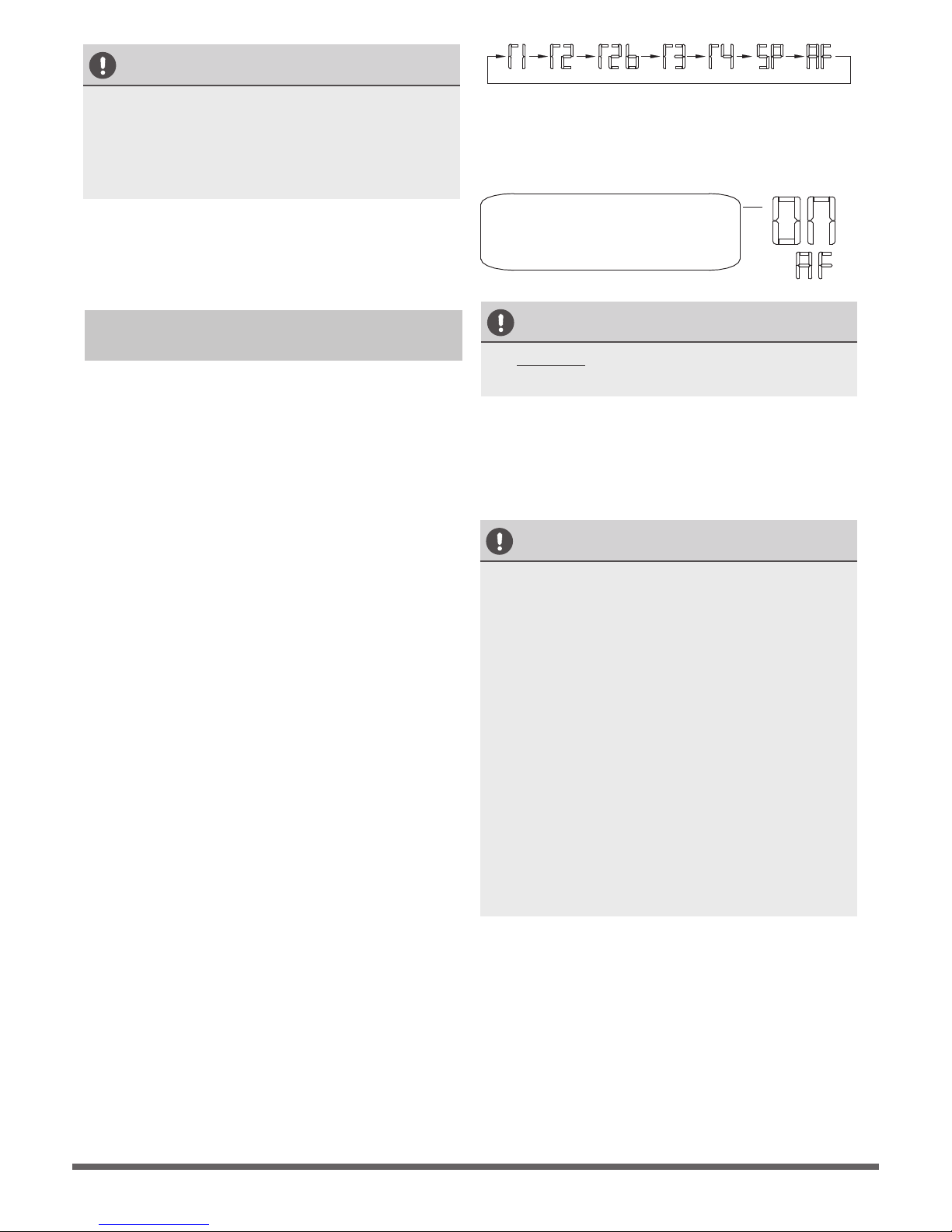
4. Set the parameters for automatic airflow
adjustment. When the air conditioning unit
is off, perform the follwoing steps:
- Press“COPY”.
- Press “+” or “-” to select the AF.
- Press “CONFIRM”. The air conditioning
unit will then start the fan for airflow
automatic adjustment.
ON will flash during when the
fan is on during automatic
airflow adjustment.
After 3 to 6 minutes, the air conditioning
unit stops operating once automatic airflow
adjustment has finished.
CAUTION
• DO NOT adjust the dampers when
automatic airflow adjustment is active.
CAUTION
• If there is no change after airflow
adjustment in the ventilation paths, be sure
to reset automatic airflow adjustment.
• If there is no change to ventilation paths
after airflow adjustment,contact your
dealer, especially if this occurs after
testing the outdoor unit or if the unit has
been moved to a different location.
• Do not use automatic airflow adjustment
with remote control,if you are using
booster fans, outdoor air processing unit,
or a HRV via duct.
• If the ventilation paths have been changed,
reset airflow automatic adjustment as
described from step 3 onwards.
CAUTION
• While connecting the wires, please strictly
follow the wiring diagram.
• The refrigerant circuit can become very
hot. Keep the interconnection cable away
from the copper tube.
4.
Clamp down the cable with the cable clamp.
The cable must not be loose or pull on the
u-lugs.
5. Reinstall the electric box cover .
Using the wire controller to set external
static pressure (some models)
Page 25
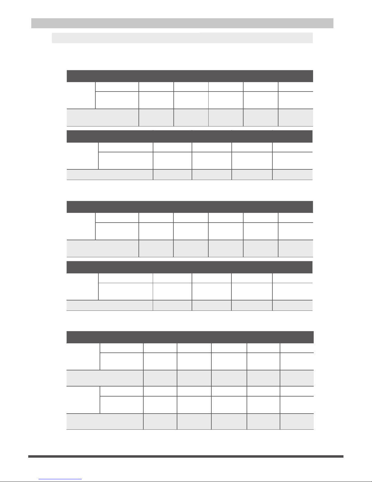
Power Specifications
NOTE: Electric auxiliary heating type circuit bre
aker/fuse need to add more than 10 A.
Indoor Power Supply Specifications
MODEL
(Btu/h)
≤18K 19K~24K 25K~36K 37K~48K 49K~60K
POWER
PHASE 1 Phase 1 Phase 1 Phase 1 Phase 1 Phase
VOLT
VOLT
VOLT
VOLT
VOLT
VOLT
208-240V 208-240V 208-240V 208-240V 208-240V
CIRCUIT BREAKER/
FUSE(A)
25/20 32/25 50/40 70/55 70/60
MODEL
(Btu/h)
≤36K 37K~60K ≤36K 37K~60K
POWER
PHASE 3 Phase 3 Phase 3 Phase 3 Phase
380-420V 380-420V 208-240V 208-240V
CIRCUIT BREAKER/FUSE(A) 25/20 32/25 32/25 45/35
MODEL
(Btu/h)
≤18K 19K~24K 25K~36K 37K~48K 49K~60K
POWER
PHASE 1 Phase 1 Phase 1 Phase 1 Phase 1 Phase
208-240V 208-240V 208-240V 208-240V 208-240V
CIRCUIT BREAKER/
FUSE(A)
25/20 32/25 50/40 70/55 70/60
MODEL
(Btu/h)
≤36K 37K~60K ≤36K 37K~60K
POWER
PHASE 3 Phase 3 Phase 3 Phase 3 Phase
380-420V 380-420V 208-240V 208-240V
CIRCUIT BREAKER/FUSE(A) 25/20 32/25 32/25 45/35
Outdoor Power Supply Specifications
Independent Power Supply Specifications
MODEL
(Btu/h)
≤18K 19K~24K 25K~36K 37K~48K 49K~60K
POWER
(indoor)
PHASE 1 Phase 1 Phase 1 Phase 1 Phase 1 Phase
208-240V 208-240V 208-240V208-240V 208-240V
CIRCUIT BREAKER/
FUSE(A)
15/10 15/10 15/10 15/10 15/10
POWER
(outdoor)
PHASE 1 Phase 1 Phase 1 Phase 1 Phase 1 Phase
208-240V 208-240V 208-240V
208-240V
208-240V
CIRCUIT BREAKER/
FUSE(A)
25/20 32/25 50/40 70/55 70/60
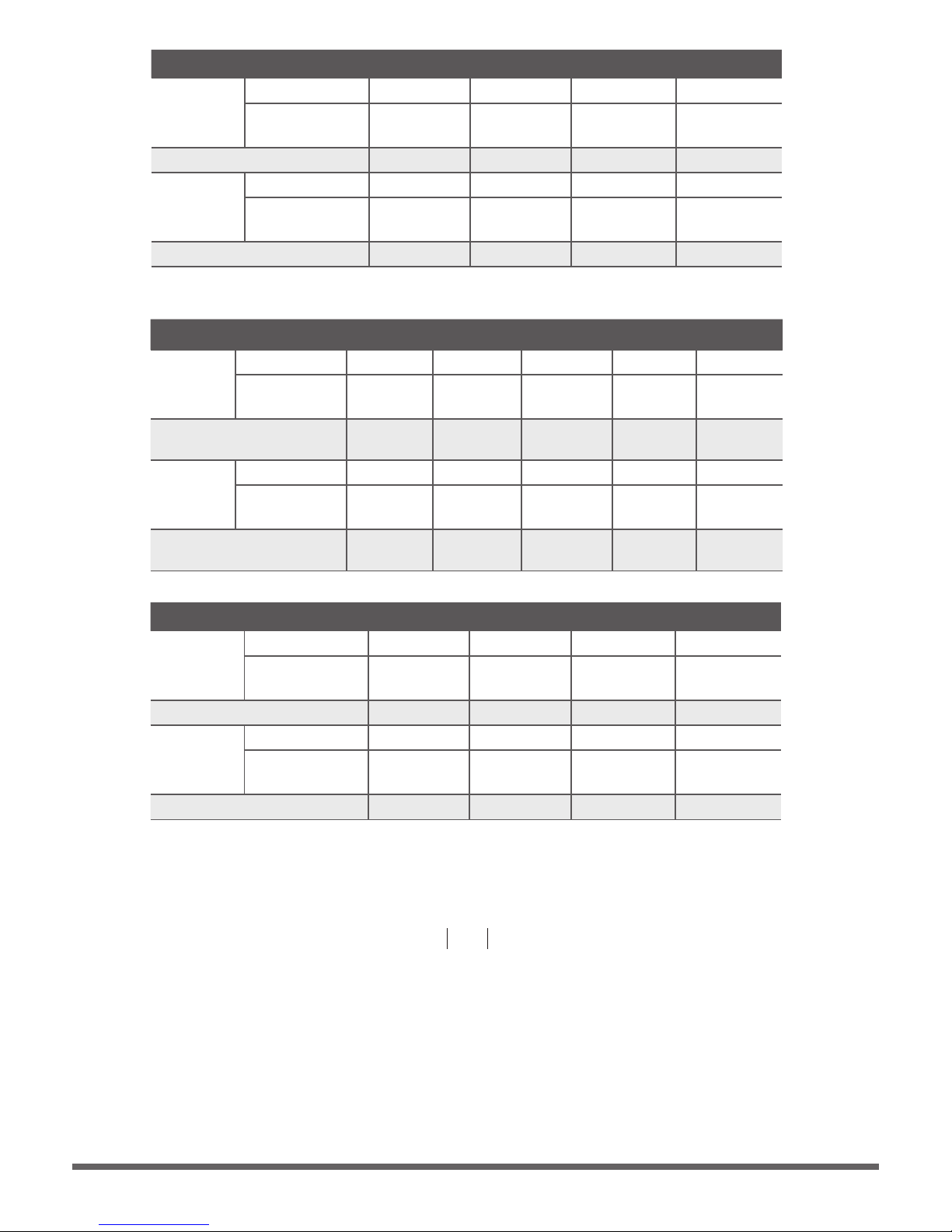
Page 26
MODEL
(Btu/h)
≤18K 19K~24K 25K~36K 37K~48K 49K~60K
POWER
(indoor)
PHASE 1 Phase 1 Phase 1 Phase 1 Phase 1 Phase
220-240V 220-240V 220-240V220-240V 220-240V
CIRCUIT BREAKER/
FUSE(A)
15/10 15/10 15/10 15/10 15/10
POWER
(outdoor)
PHASE 1 Phase 1 Phase 1 Phase 1 Phase 1 Phase
208-240V 208-240V 208-240V
208-240V
208-240V
CIRCUIT BREAKER/
FUSE(A)
25/20 25/20 40/30 50/40 50/40
MODEL
(Btu/h)
≤36K 37K~60K ≤36K 37K~60K
POWER
(indoor)
PHASE 1 Phase 1 Phase 1 Phase 1 Phase
VOLT
VOLT
VOLT
VOLT
VOLT
VOLT
208-240V 208-240V 208-240V 208-240V
CIRCUIT BREAKER/FUSE(A) 15/10 15/10 15/10 15/10
POWER
(outdoor)
PHASE 3 Phase 3 Phase 3 Phase 3 Phase
380-420V 380-420V 208-240V 208-240V
CIRCUIT BREAKER/FUSE(A) 25/20 32/25 32/25 45/35
MODEL
(Btu/h)
≤36K 37K~60K ≤36K 37K~60K
POWER
(indoor)
PHASE 1 Phase 1 Phase 1 Phase 1 Phase
220-240V 220-240V 220-240V 220-240V
CIRCUIT BREAKER/FUSE(A) 15/10 15/10 15/10 15/10
POWER
(outdoor)
PHASE 3 Phase 3 Phase 3 Phase 3 Phase
380-420V 380-420V 208-240V 208-240V
CIRCUIT BREAKER/FUSE(A) 25/20 32/25 32/25 40/30
Inverter Type A/C Power Specifications
NOTE:
To be in compliance with EN61000-3-11, the product shall be connected
= 0.267802236 Ω or less. Before connecting only to a supply of the system impedance: Zsys
the product to public power network, please consult your local power supply authority to
ensure the power network meet above requirement.
Page 27
Air Evacuation
Safety Precautions
CAUTION
• Use a vacuum pump with a gauge reading
lower than -0.1MPa and an air discharge
capacity above 40L/min.
• The outdoor unit does not need vacuuming.
DO NOT open the outdoor unit’s gas and
liquid stop valves.
• Ensure that the Compound Meter reads
-0.1MPa or below after 2 hours. If after
three hours the gauge reading is still above
-0.1MPa, check if there is a gas leak or
water inside the pipe. If there is no leak,
perform another evacuation for 1 or 2 hours.
•
DO NOT use refrigerant gas to evacuate the
system.
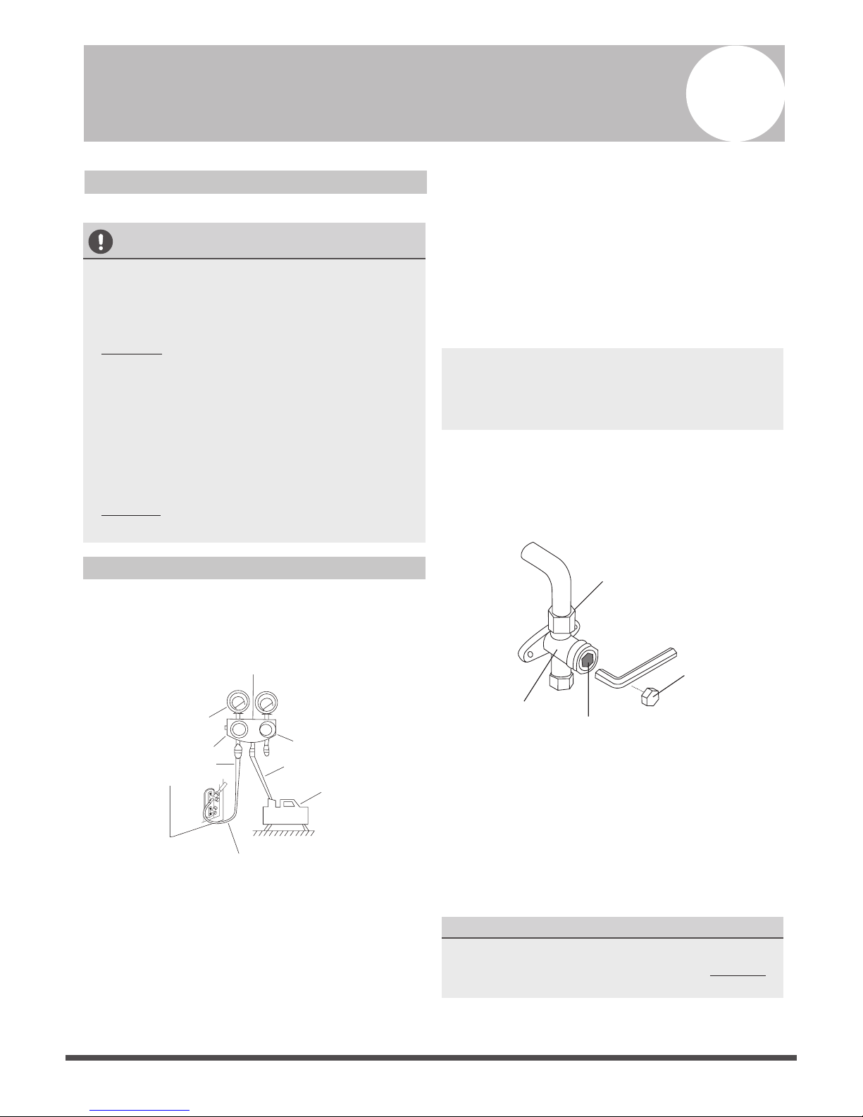
Evacuation Instructions
Before using a manifold gauge and a vacuum
pump, read their operation manuals to make
sure you know how to use them properly.
Manifold Gauge
Compound gauge
-76cmHg
Low pressure valve
High pressure valve
Charge hose
Charge hose
Vacuum pump
Pressure gauge
Low pressure valve
Fig. 9.1
1. Connect the manifold gauge’s charge hose to
the service port on the outdoor unit’s low
pressure valve.
2. Connect the manifold gauge’s charge hose
from the to the vacuum pump.
3. Open the Low Pressure side of the manifold
gauge. Keep the High Pressure side closed.
4. Turn on the vacuum pump to evacuate the
system.
5. Run the vacuum for at least 15 minutes, or
until the Compound Meter reads -76cmHG
(-1x10⁵Pa).
6. Close the manifold gauge’s Low Pressure valve
and turn off the vacuum pump.
7. Wait for 5 minutes, then check that there has
been no change in system pressure.
NOTE: If there is no change in system pressure,
unscrew the cap from the packed valve (high
pressure valve). If there is a change in system
pressure, there may be a gas leak.
8. Insert hexagonal wrench into the packed valve
(high pressure valve) and open the valve by
turning the wrench in a 1/4 counterclockwise
turn. Listen for gas to exit the system, then
close the valve after 5 seconds.
Flare nut
Cap
Valve body
Valve stem
Fig. 9.2
9. Watch the Pressure Gauge for one minute to
make sure that there is no change in pressure. It
should read slightly higher than the atmospheric
pressure.
10.Remove the charge hose from the service port.
11.Using hexagonal wrench, fully open both the
high pressure and low pressure valves.
OPEN VALVE STEMS GENTLY
When opening valve stems, turn the hexagonal
wrench until it hits against the stopper. DO NOT
try to force the valve to open further.
12.Tighten valve caps by hand, then tighten it
using the proper tool.
9
Page 28
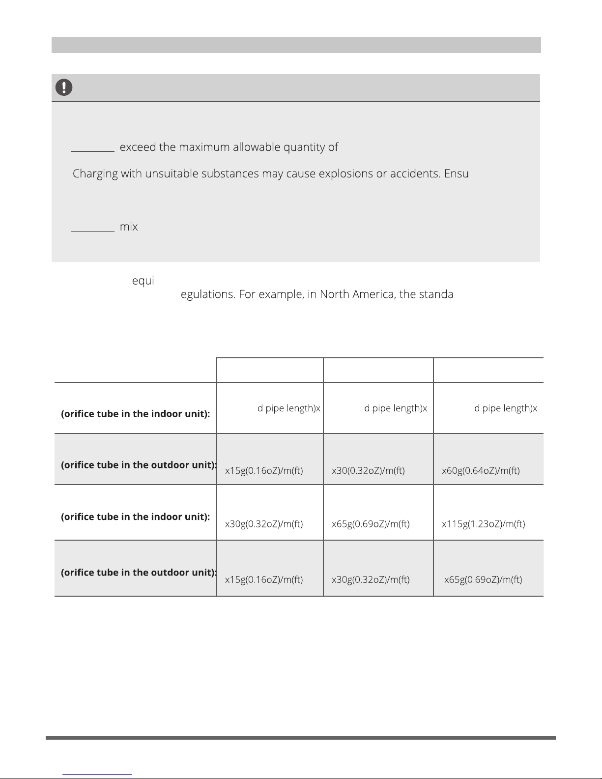
Note On Adding Refrigerant
CAUTION
• Refrigerant charging must be performed after wiring, vacuuming, and the leak testing.
• DO NOT refrigerant or overcharge the system.
Doing so can damage the unit or impact it’s functioning.
•
re that the
appropriate refrigerant is used.
• Refrigerant containers must be opened slowly. Always use protective gear when charging the
system.
• DO NOT refrigerants types.
Some systems r
re additional charging depending on pipe lengths. The standard pipe length
varies according to local r rd pipe length is
7.5m (25’) In other areas, the standard pipe length is 5m (16‘). The additional refrigerant to be
charged can be calculated using the following formula:
Liquid Side Diameter
φ6.35(1/4”) φ9.52(3/8”) φ12.7(1/2”)
R22
(Total pipe length standar
30g (0.32oZ)/m(ft)
(Total pipe length standar
65g(0.69oZ)/m(ft)
(Total pipe length standar
115g(1.23oZ)/m(ft)
R22
(Total pipe length standard pipe length)
(Total pipe length standard pipe length)
(Total pipe length -
standard pipe length)
(Total pipe length -
standard pipe length)
R410A:
(Total pipe length standard pipe length)
(Total pipe length standard pipe length)
(Total pipe length standard pipe length)
R410A:
(Total pipe length standard pipe length)
(Total pipe length standard pipe length)

Page 29
Before Test Run
A test run must be performed after the entire
system has been completely installed. Confirm
the following points before performing the test:
a) Indoor and outdoor units are properly
installed.
b) Piping and wiring are properly connected.
c) No obstacles near the inlet and outlet of the
unit that might cause poor performance or
product malfunction.
d) Refrigeration system does not leak.
e) Drainage system is unimpeded and
draining to a safe location.
f) Heating insulation is properly installed.
Grounding wires are properly connected.
g)
h) Length of the piping and the added
refrigerant stow capacity have been
recorded.
i) Power voltage is the correct voltage for the
air conditioner.
CAUTION
Failure to perform the test run may result in unit
damage, property damage, or personal injury.
Test Run Instructions
1. Open both the liquid and gas stop valves.
2. Turn on the main power switch and allow the
unit to warm up.
3. Set the air conditioner to COOL mode.
4. For the Indoor Unit
a. Ensure the remote control and its buttons
work properly.
b. Ensure the louvers move properly and can
be changed using the remote control.
c. Double check to see if the room
temperature is being registered correctly.
d. Ensure the indicators on the remote
control and the display panel on the indoor
unit work properly.
e. Ensure the manual buttons on the indoor
unit works properly.
f. Check to see that the drainage system is
unimpeded and draining smoothly.
g. Ensure there is no vibration or abnormal
noise during operation.
5. For the Outdoor Unit
a. Check to see if the refrigeration system is
leaking.
b. Make sure there is no vibration or
abnormal noise during operation.
c. Ensure the wind, noise, and water
generated by the unit do not disturb your
neighbors or pose a safety hazard.
6. Drainage Test
a. Ensure the drainpipe flows smoothly. New
buildings should perform this test before
finishing the ceiling.
b. Remove the test cover. Add 2,000ml of
water to the tank through the attached
tube.
c. Turn on the main power switch and run
the air conditioner in COOL mode.
d. Listen to the sound of the drain pump to
see if it makes any unusual noises.
e. Check to see that the water is discharged.
It may take up to one minute before the
unit begins to drain depending on the
drainpipe.
f. Make sure that there are no leaks in any of
the piping.
g. Stop the air conditioner. Turn off the main
power switch and reinstall the test cover.
NOTE: If the unit malfunctions or does not
operate according to your expectations, please
refer to the Troubleshooting section of the
Owner’s Manual before calling customer service.
Test Run
10

Page 30
The design and specifications are subject to change without prior notice for product
improvement. Consult with the sales agency or manufacturer for details.

Page 31

Σελίδα 2
Εγχειρίδιο Εγκατάστασης
Περιεχόμενα
1 Εξαρτήματα........................................04
α. Μέρη εσωτερικής μονάδας..................................08
β. Οδηγίες εγκατάστασης εσωτερικής μονάδας....09
α. Οδηγίες εγκατάστασης εξωτερικής μονάδας……..... 13
β. Τύποι και προδιαγραφές εξωτερικών μονάδων…… 14
γ. Σημειώσεις για τη διάτρηση σε τοίχους.....................14
2 Προφυλάξεις ασφαλείας.................. 05
3 Επισκόπηση εγκατάστασης..............07
6 Εγκατάσταση σωλήνα αποχέτευσης...............15
4 Εγκατάσταση εσωτερικής μονάδας..................07
5 Εγκατάσταση εξωτερικής μονάδας.................... 12
MC MC
L N

Σελίδα 3
MC MC
L N
α. Σημειώσεις για το μήκος και το ύψος των σωλήνων .....18
β. Οδηγίες σύνδεσης σωλήνων ψυκτικού υγρού ...............20
α. Οδηγίες εκκένωσης...........................................................27
β. Σημείωση για την προσθήκη ψυκτικού .........................28
α. Καλωδίωση εξωτερικής μονάδας......... 22
β. Καλωδίωση εσωτερικής μονάδας........ 23
γ. Προδιαγραφές ισχύoς............................. 25
7 Σύνδεση σωληνώσεων ψυκτικού.................................18
9 Εκκένωση του αέρα........................................................27
10 Δοκιμαστική Λειτουργία..................................................29
8 Καλωδίωση..............................................20

Σελίδα 4
S1&S2(P&Q&E)
Εξαρτήματα
1
Το κλιματιστικό μηχάνημα διαθέτει τα εξαρτήματα που παρατίθενται παρακάτω. Χρησιμοποιήστε
όλα τα μέρη και εξαρτήματα εγκατάστασης για να εγκαταστήσετε το κλιματιστικό. Τυχόν εσφαλμένη
εγκατάσταση μπορεί να προκαλέσει διαρροή νερού, ηλεκτροπληξία και πυρκαγιά ή καταστροφή του
εξοπλισμού.
Υπάρχουν δύο τύποι τηλεχειριστηρίων: ενσύρματα και ασύρματα. Επιλέξτε τηλεχειριστήριο με
βάση τις απαιτήσεις και τοποθετήστε το σε κατάλληλο σημείο.
Συμβουλευθείτε καταλόγους και τεχνικά έντυπα για καθοδήγηση ως προς την επιλογή του
κατάλληλου τηλεχειριστηρίου.
ΟΝΟΜΑ ΣΧΗΜΑ ΠΟΣΟΣΤΗΤΑ
Σωληνώσεις και
εξαρτήματα σύνδεσης
Ηχοαπορροφητική / μονωτική επένδυση 2
1
1
1
1
1
1
1
1
1
Αφρώδες υλικό στεγανοποίησης (ορισμένα μοντέλα)
Στόμιο (ορισμένα μοντέλα)
Σύνδεσμος αποχέτευσης (ορισμένα μοντέλα)
Δακτύλιος στεγανοποίησης (ορισμένα μοντέλα)
Εγχειρίδιο χρήστη
Εγχειρίδιο εγκατάστασης
Συνδετήριο καλώδιο για την οθόνη (2m)
Ελαστικός δακτύλιος προστασίας καλωδίου
Μαγνητικός δακτύλιος
(για να περιβάλλει τα καλώδια S1 & S2 ( P & Q & E )
γύρω από το μαγνητικό δακτύλιο δύο φορές)
Μαγνητικός δακτύλιος
(αγκιστρώστε στο καλώδιο σύνδεσης μεταξύ της
εσωτερικής μονάδας και της εξωτερικής μονάδας μετά
από την εγκατάσταση)
Σύνδεσμος μεταφοράς (φ12.7-Φ 15.9)/ (Φ 0.5 i n-Φ 0.63
(συσκευασμένος με την εσωτερική μονάδα)
ΣΗΜΕΙΩΣΗ: Το μέγεθος σωλήνα μπορεί να ποικίλλει
ανάλογα με τη συσκευή. Για να καλυφθούν οι
επιμέρους απαιτήσεις μεγέθους σωλήνα, μερικές
φορές οι συνδέσεις χρειάζονται σύνδεσμο μεταφοράς
τοποθετημένο στην εξωτερική μονάδα.
Σύνδεσμος μεταφοράς (Φ6.35-Φ9.52)/ ( Φ0 .25 i n-Φ
0.375 (συσκευασμένος με την εσωτερική μονάδα)
ΣΗΜΕΙΩΣΗ: Το μέγεθος σωλήνα μπορεί να ποικίλλει
ανάλογα με τη συσκευή. Για να καλυφθούν οι
επιμέρους απαιτήσεις μεγέθους σωλήνα, μερικές
φορές οι συνδέσεις χρειάζονται σύνδεσμο μεταφοράς
τοποθετημένο στην εξωτερική μονάδα.
Σύνδεσμος μεταφοράς (Φ9.52-ΦΊ2.7)/(Φ0.3 75in- Φ 0.5 )in
(συσκευασμένος με την εσωτερική μονάδα , χρησιμοποιείται
μόνο για μοντέλα multi) ΣΗΜΕΙΩΣΗ: Το μέγεθος σωλήνα μπορεί
να ποικίλλει ανάλογα με τη συσκευή. Για να καλυφθούν οι
επιμέρους απαιτήσεις μεγέθους σωλήνα, μερικές φορές οι
συνδέσεις χρειάζονται σύνδεσμο μεταφοράς τοποθετημένο
στην εξωτερική μονάδα.
Εξαρτήματα σωλήνα
αποχέτευσης (για ψύξη
και θέρμανση)
Μαγνητικός δακτύλιος
προστασίας EMC
(ορισμένα μοντέλα)
Λοιπά
Προαιρετικά εξαρτήματα
Οθόνη λειτουργιών
*μόνο για δοκιμαστική λειτουργία
1 (για ορισμένα μοντέλα-
KJR-120G,KJR-120H)
1
(για ορισμένα μοντέλα)
1
(για ορισμένα μοντέλα)
1
(για ορισμένα μοντέλα)
1
(για ορισμένα μοντέλα)

Σελίδα 5
Προφυλάξεις Ασφαλείας
2
Μη συμμόρφωση με μια προειδοποίηση μπορεί να οδηγήσει στον θάνατο.
Η συσκευή θα πρέπει να εγκαθίσταται σύμφωνα με τους εθνικούς κανονισμούς.
ΠΡΟΕΙΔΟΠΟΙΗΣΗ
ΠΡΟΣΟΧΗ
Μη συμμόρφωση με μια σήμανση προσοχής μπορεί να οδηγήσει σε τραυματισμό
ή βλάβη του εξοπλισμού.
Διαβάστε τις προφυλάξεις ασφαλείας πριν από την εγκατάσταση.
Τυχόν εσφαλμένη εγκατάσταση που οφείλεται σε άγνοια των οδηγιών, μπορεί να προκαλέσει
σοβαρή βλάβη ή τραυματισμό. Η σοβαρότητα πιθανής βλάβης ή τραυματισμού αναφέρεται ως
ΠΡΟΕΙΔΟΠΟΙΗΣΗ ή ΠΡΟΣΟΧΗ.
ΠΡΟΕΙΔΟΠΟΙΗΣΗ
Σημείωση σχετικά με τα Φθοριούχα Αέρια
• Διαβάστε προσεκτικά τις Προφυλάξεις Ασφαλείας πριν την εγκατάσταση.
• Σε ορισμένα λειτουργικά περιβάλλοντα, όπως κουζίνες, αίθουσες εξυπηρετήσεων κλπ., συνιστάται η χρήση
ειδικών μονάδων κλιματισμού.
• Μόνο εξειδικευμένοι και πιστοποιημένοι τεχνικοί μπορούν να εγκαταστήσουν, να επισκευάσουν
και να συντηρήσουν το κλιματιστικό.
Η ακατάλληλη εγκατάσταση μπορεί να προκαλέσει ηλεκτροπληξία, βραχυκύκλωμα, διαρροές, πυρκαγιά ή
άλλες ζημιές στον εξοπλισμό και την προσωπική ιδιοκτησία.
• Τηρείτε αυστηρά τις οδηγίες εγκατάστασης που ορίζονται στο παρόν εγχειρίδιο.
Η ακατάλληλη εγκατάσταση μπορεί να προκαλέσει ηλεκτροπληξία, βραχυκύκλωμα, διαρροές, πυρκαγιά ή
άλλες ζημιές στον εξοπλισμό.
• Πριν εγκαταστήσετε τη μονάδα, εξετάστε τους ισχυρούς ανέμους, τους τυφώνες και τους σεισμούς
που μπορεί να προκαλέσουν βλάβες στη μονάδα σας και δράστε ανάλογα. Διαφορετικά ενδέχεται να
προκληθούν ζημιές στο κλιματιστικό σας.
• Μετά την εγκατάσταση, βεβαιωθείτε ότι δεν υπάρχουν διαρροές ψυκτικού μέσου και ότι η μονάδα
λειτουργεί σωστά. Το ψυκτικό μέσο είναι τοξικό και εύφλεκτο και μπορεί να προκαλέσει σοβαρό κίνδυνο
στην υγεία και την ασφάλεια σας.
1. Αυτή η μονάδα κλιματισμού περιέχει φθοριούχα αέρια. Για ειδικές πληροφορίες σχετικά με τον τύπο και
τη ποσότητα του αερίου, ανατρέξτε στη σχετική ετικέτα που φέρει η μονάδα.
2. Η εγκατάσταση, η συντήρηση και η επισκευή αυτής της συσκευής πρέπει να γίνεται από πιστοποιημένο
τεχνικό.
3. Η απεγκατάσταση και η ανακύκλωση του προϊόντος πρέπει να εκτελούνται από πιστοποιημένο τεχνικό.
4. Εάν το σύστημα έχει εγκατεστημένο σύστημα ανίχνευσης διαρροών, πρέπει να ελέγχεται για διαρροές
τουλάχιστον κάθε 12 μήνες.
5. Όταν η μονάδα ελέγχεται για διαρροές, συνιστάται η σωστή καταγραφή όλων των ελέγχων.

Σελίδα 6
LN
1
2
3
4
5
MC MC
6
7
Επισκόπηση εγκατάστασης
3
ΣΕΙΡΑ ΕΓΚΑΤΑΣΤΑΣΗΣ
Τοποθετήστε την
εσωτερική μονάδα
(Σελίδα 9)
Εκκενώστε το ψυκτικό
σύστημα (Σελίδα 27)
Προβείτε σε δοκιμαστική
λειτουργία (Σελίδα 29)
Συνδέστε τα καλώδια
(Σελίδα 22)
Συνδέστε τους σωλήνες
ψυκτικού (Σελίδα 19)
Τοποθετήστε την
εξωτερική μονάδα
(Σελίδα 15)
Τοποθετήστε το
σωλήνα αποχέτευσης
(Σελίδα 17)

Σελίδα 7
Εγκατάσταση εσωτερικής μονάδας
4
Μέρη εσωτερικής μονάδας
Προφυλάξεις Ασφαλείας
Οδηγίες εγκατάστασης εσωτερικής μονάδας
Είσοδος αέρα
Εξαγωγή αέρα
Εικ. 4.1
Ερμάριο ηλεκτρολογικού ελέγχου
Φίλτρο αέρα (σε ορισμένα μοντέλα)
Σωλήνας αποχέτευσης
Σωλήνας σύνδεσης ψυκτικού
ΠΡΟΕΙΔΟΠΟΙΗΣΗ ΠΡΟΣΟΧΗ
ΠΡΟΣΟΧΗ
• Εγκαταστήσετε σταθερά την εσωτερική μονάδα σε
κατασκευή, η οποία να μπορεί να αντέξει το βάρος της.
Εάν η εν λόγω κατασκευή δεν είναι στιβαρή, η μονάδα
ενδέχεται να πέσει και να προκληθεί τραυματισμός, βλάβη
στη μονάδα ή άλλες υλικές ζημίες ή θάνατος.
• ΜΗΝ τοποθετείτε την εσωτερική μονάδα σε μπάνιο ή
πλυσταριό, καθώς η υπερβολική υγρασία από αυτούς
τους χώρους ενδέχεται να προκαλέσει βραχυκύκλωμα της
μονάδας και διάβρωση των καλωδίων.
Βήμα 1: Επιλέξτε τη θέση εγκατάστασης
Η εσωτερική μονάδα θα πρέπει να εγκατασταθεί σε θέση που
να καλύπτει τις παρακάτω προϋποθέσεις:
ΜΗΝ εγκαθιστάτε τη μονάδα στις θέσεις που αναφέρονται
παρακάτω:
Υπάρχει αρκετός χώρος για εγκατάσταση και συντήρηση.
Υπάρχει αρκετός χώρος για τη σύνδεση των σωληνώσεων και
του αγωγού αποχέτευσης.
Η οροφή είναι οριζόντια και η κατασκευή της μπορεί να
δέχεται το βάρος της εσωτερικής μονάδας.
Η εισαγωγή και η εξαγωγή αέρα δεν παρεμποδίζονται.
Η ροή αέρα μπορεί να διοχετευθεί σε ολόκληρο το δωμάτιο.
Δεν υπάρχει απευθείας ακτινοβολία από θερμαντικά σώματα.
Η εγκατάσταση είναι εντοιχισμένη
Σε ένα δωμάτιο μπορούν να εγκατασταθούν κλιματιστικά από
9.000btu/h έως 18.000btu/h.
Περιοχές στις οποίες πραγματοποιείται εξόρυξη
πετρελαίου ή φυσικού αερίου
Παράκτιες περιοχές με υψηλή περιεκτικότητα σε αλάτι
στην ατμόσφαιρα
Θέσεις όπου ο αέρας περιέχει καυστικά αέρια, όπως π.χ.
κοντά σε ιαματικές πηγές
Περιοχές όπου εμφανίζονται διακυμάνσεις του ρεύματος,
π.χ. εργοστάσια
Κλειστοί χώροι, π.χ. ερμάρια
Περιοχές όπου υπάρχουν ισχυρά ηλεκτρομαγνητικά
κύματα
Περιοχές όπου φυλάσσονται εύφλεκτα υλικά ή αέριο
Δωμάτια με υψηλή υγρασία π.χ. μπάνιο ή πλυσταριό
• Εγκαταστήστε την εσωτερική / εξωτερική μονάδα, τα
καλώδια και τους αγωγούς τους σε απόσταση τουλάχιστον
1m (3.2’) από συσκευές τηλεόρασης και ραδιόφωνου
ώστε να μην προκαλούνται παράσιτα ή παραμόρφωση
της εικόνας. Ανάλογα με τις συσκευές, η απόσταση του 1m
(3.2’) ενδέχεται να μην είναι επαρκής.
• Εάν η εσωτερική μονάδα τοποθετηθεί επάνω σε μεταλλικό
μέρος του κτιρίου, θα πρέπει να είναι ηλεκτρικά γειωμένη.

Σελίδα 8
>4in(10cm) >11.8in(30cm)
>0.8in(2cm)
>0.8in(2cm)
>11.8in(30cm)
)mc052(ni2.8 >
B
Εικ. 4.2
>
7.9
in
(20cm)
11.8in
23.6inx23.6in (60cmx60cm)
> (30cm)
Εικ. 4.3
A B C D E F I
J
G
H
18K 210/8.3 674/26.5880/34.6
24K 249/9.8 774/30.51100/43.3
30K~36K 249/9.8 774/30.51360/53.5
36K~60K 300/11.8 874/34.41200/47.2
136/5.4 706/27.8600/23.6
175/6.9 926/36.5700/27.6
175/6.9 1186/46.7700/27.6
227/8.9 1044/41.1800/31.5
190/7.5
228/8.9
228/8.9
280/11
920/36.2782/30.8
1140/44.91001/39.4
1400/55.11261/49.6
1240/48.81101/43.3
508/20
598/23.5
598/23.5
697/27.4
9K/12K
200/7.9 506/19.9700/27.6 152/6 537/21.1450/17.7 186/7.3 741/29.2599/23.6
360/14.2
Εικ. 4.6
Εικ. 4.7
Εικ. 4.4
Εικ. 4.5
Βήμα 2: Ανάρτηση εσωτερικής μονάδας
1. Συμβουλευθείτε τα παρακάτω διαγράμματα για να εντοπίσετε τις οπές των βιδών τοποθέτησης στην
οροφή. Φροντίστε να σημαδέψετε τα σημεία όπου θα γίνει η διάτρηση για τις οπές ανάρτησης οροφής.
Διαστάσεις εξόδου αέρα
Τοποθεσία εγκατάστασης
Τοποθεσία συντήρησης
Στοιβαρή Οροφή
Εξαγωγή Αέρα
Εισαγωγή Αέρα
Έλεγχος
Πρόσβαση
για επισκευή
Οροφή
Δάπεδο
(Όταν δεν υπάρχει οροφή)
Εσωτερική Μονάδα
Αριστερή
Πλευρά
Δεξιά
Πλευρά

Σελίδα 9
Εικ. 4.3
A B C D E F I
J
G
H
18K 210/8.3 674/26.5880/34.6
24K 249/9.8 774/30.51100/43.3
30K~36K 249/9.8 774/30.51360/53.5
36K~60K 300/11.8 874/34.41200/47.2
136/5.4 706/27.8600/23.6
175/6.9 926/36.5700/27.6
175/6.9 1186/46.7700/27.6
227/8.9 1044/41.1800/31.5
190/7.5
228/8.9
228/8.9
280/11
920/36.2782/30.8
1140/44.91001/39.4
1400/55.11261/49.6
1240/48.81101/43.3
508/20
598/23.5
598/23.5
697/27.4
9K/12K
200/7.9 506/19.9700/27.6
152/6 537/21.1450/17.7 186/7.3 741/29.2599/23.6
360/14.2
Εικ. 4.6
Εικ. 4.7
Εικ. 4.4
Εικ. 4.5
Διαστάσεις εισόδου αέρα
Κατερχόμενο άνοιγμα εξαερισμού και τοποθετημένο άγκιστρο
Φίλτρο αέρα
Φίλτρο αέρα
Κιβώτιο ηλεκτρολογικού ελέγχου
Πίνακας.4-1
ΜΟΝΤΕΛΟ
(Btu/h)
(μονάδα: mm/ίντσες)
Ξύλο
Τοποθετήστε το ξύλινο στήριγμα κατά πλάτος της
δοκού οροφής και στη συνέχεια τοποθετήστε τους
κοχλίες ανάρτησης.
(Βλέπε Εικ. 4.4)
Νέα κατασκευή με τούβλο
Διείσδυση ή εγκιβωτισμός των κοχλιών.
(Βλέπε Εικ. 4.5)
Προϋπάρχουσα κατασκευή με τούβλο
Χρησιμοποιήστε βίδα εγκιβωτισμού, τρίψτε και
κολλήστε τον αναρτήρα. (Βλ. Εικ. 4.6)
Κατασκευή οροφής με χαλυβδοδοκούς
Εγκαταστήστε και χρησιμοποιείστε τη χαλυβδογωνία
υποστήριξης. (Βλ. Εικ. 4.7)
Ξύλινο στήριγμα
Δοκός οροφής
Ανάρτηση οροφής
Κοχλίες
(Εισαγωγή σχήματος πτερυγίου)
Αναρτώμενος κοχλίας
Χαλυβδογωνία
στήριξης
Κοχλίες
ανάρτησης
Κοχλίας εγκιβωτισμού (κοχλίας ανάρτησης σωλήνα και εγκιβωτισμού)
(Συρόμενη εισαγωγή)
Διαστάσεις περιγράμματος
Μέγεθος ανοίγματος
εξόδου αέρα
Μέγεθος ανοίγματος
επιστροφής αέρα
Μέγεθος σφιγκτήρα
τοποθέτησης

Σελίδα 10
Εικ. 4.10
or more.
0~100/0~0.4
18K
0~160/0~0.64
24K
0~160/0~0.64
30K~36K
0~160/0~0.64
42K~60K
0~50/0~0.2
9K
0~50/0~0.2
12K
Εικ. 4.9
Εικ. 4.8
Βήμα 3: Εγκατάσταση αεραγωγού και παρελκομένων
1. Τοποθετήστε το φίλτρο (προαιρετικό) ανάλογα με το
μέγεθος της εισόδου αέρα.
2. Τοποθετήστε τον υφασμάτινο σύνδεσμο μεταξύ του κορμού
και του αεραγωγού.
3. Οι αεραγωγοί εισόδου και εξόδου αέρα θα πρέπει να
βρίσκονται σε αρκετή απόσταση μεταξύ τους για να μην
υπάρχει βραχυκύκλωμα στην κυκλοφορία του αέρα.
4. Συνδέστε τον αεραγωγό με βάση το παρακάτω διάγραμμα:
5. Συμβουλευθείτε τις παρακάτω οδηγίες στατικής πίεσης κατά
την εγκατάσταση της εσωτερικής μονάδας.
Αλλάξτε τη στατική πίεση του μοτέρ του ανεμιστήρα
ανάλογα με την εξωτερική στατική πίεση του αεραγωγού.
ΣΗΜΕΙΩΣΗ:
1. Μην αφήνετε την εσωτερική μονάδα να δέχεται το
βάρος του συνδετήριου αεραγωγού.
2. Κατά τη σύνδεση του αεραγωγού, χρησιμοποιήστε
υφασμάτινο μη εύφλεκτο εξάρτημα σύνδεσης για
την αποφυγή κραδασμών.
3. Θα πρέπει να τυλίξετε αφρώδες μονωτικό
(αρμαφλέξ) γύρω από τον αεραγωγό για να
αποφευχθούν συμπυκνώματα. Μπορεί να
προστεθεί εσωτερικό υπόστρωμα στον αεραγωγό
για την ελάττωση του θορύβου.
Πίνακας 4-2
Υφασμάτ. σύνδεσμος Υφασμάτ. σύνδεσμος
Θάλαμος απομόνωσης
Θάλαμος
απομόνωσης
Εξαγωγή
αέρα
Είσοδος αέρα
Φίλτρο σκόνης
Στόμιο ελέγχου
ΜΟΝΤΕΛΟ
(Btu/h)
Στατική πίεση
(Pa)
Ο κορμός της μονάδας θα πρέπει να είναι απολύτως
ευθυγραμμισμένος με την οπή. Βεβαιωθείτε ότι η μονάδα
και η οπή είναι ίδιου μεγέθους, προτού συνεχίσετε.
ΠΡΟΣΟΧΗ
2. Εγκαταστήστε και στερεώστε σωλήνες και αγωγούς μετά
την ολοκλήρωση της εγκατάστασης του κυρίως κορμού.
Κατά την επιλογή του σημείου έναρξης, βρείτε την
κατεύθυνση όπου θα οδεύσουν οι σωλήνες. Ειδικά σε
περιπτώσεις όπου υπάρχει οροφή, τοποθετήστε τους
σωλήνες ψυκτικού, τους σωλήνες αποχέτευσης και τις
γραμμές ρεύματος εσωτερικής / εξωτερικής μονάδας
στα σημεία σύνδεσης πριν από τη συναρμολόγηση της
μονάδας.
3. Εγκαταστήστε τους κοχλίες ανάρτησης.
• Κόψτε τη δοκό οροφής.
• Ενισχύστε το σημείο όπου έγινε η κοπή. Στερεώστε καλά
τη δοκό οροφής.
4. Μετά την επιλογή της θέσης εγκατάστασης,
ευθυγραμμίστε τους σωλήνες ψυκτικού, τους σωλήνες
αποχέτευσης και τα καλώδια εσωτερικής / εξωτερικής
μονάδας με τα σημεία σύνδεσής τους πριν από τη
συναρμολόγηση της μονάδας.
5. Ανοίξτε 4 οπές σε βάθος 10 εκ (4”) στις θέσεις των
γάντζων οροφής, στην εσωτερική επιφάνεια της οροφής.
Κρατήστε το δράπανο σε γωνία 90° ως προς την οροφή.
6. Σφίξτε τον κοχλία με τις παρεχόμενες ροδέλες και
παξιμάδια.
7. Εγκαταστήστε τους τέσσερις κοχλίες ανάρτησης.
8. Κατά τη συναρμολόγηση της εσωτερικής μονάδας θα
χρειαστούν τουλάχιστον δύο άτομα για την ανύψωση
και τη στερέωσή της. Εισάγετε τους κοχλίες ανάρτησης
στις οπές ανάρτησης της μονάδας. Στερεώστε τους με τις
παρεχόμενες ροδέλες και παξιμάδια. (Βλέπε Εικ. 4.8).
9. Τοποθετήστε την εσωτερική μονάδα επάνω στους
αναρτώμενους κοχλίες με τάκο. Τοποθετήστε οριζόντια
την εσωτερική μονάδα χρησιμοποιώντας αλφάδι, για να
αποφευχθούν διαρροές.
(Βλέπε Εικ. 4.9).
ΣΗΜΕΙΩΣΗ: Βεβαιωθείτε ότι η ελάχιστη ρύση
αποχέτευσης είναι 1/100 ή περισσότερο.
Παξιμάδι κοχλία
Αποσβεστήρας κραδασμών
Αναρτώμενος κοχλίας
Ροδέλα
Προεξέχον μέρος

Σελίδα 11
Ø125mm(4.92”)
Ø160mm(6.3”)
18-60
Βήμα 4: Ρύθμιση της κατεύθυνσης εισαγωγής αέρα
(Από την οπίσθια προς την κάτω πλευρά.)
1. Βγάλτε το πάνελ αερισμού και τη φλάντζα.
Βήμα 5: Εγκατάσταση αεραγωγού νωπού αέρα
Διάσταση:
Βήμα 6: Συντήρηση μοτέρ και αντλίας
συμπυκνωμάτων
(το πίσω αεριζόμενο πάνελ χρησιμοποιείται ως
παράδειγμα)
Συντήρηση μοτέρ:
1. Βγάλτε το αεριζόμενο πάνελ.
2. Βγάλτε το κάλυμμα του ανεμιστήρα.
3. Βγάλτε το μοτέρ.
Συντήρηση αντλίας:
1. Αφαιρέστε τέσσερις βίδες από την αντλία
συμπυκνωμάτων.
2. Αποσυνδέστε την παροχή ρεύματος της αντλίας
και το καλώδιο του διακόπτη στάθμης νερού.
3. Απομακρύνετε την αντλία.
2. Αλλάξτε τις θέσεις συναρμολόγησης του πάνελ
εξαερισμού και της φλάντζας επιστροφής αέρα.
3. Κατά την εγκατάσταση του πλέγματος φίλτρου,
τοποθετήστε το μέσα στη φλάντζα όπως εικονίζεται στην
παρακάτω εικόνα.
ΣΗΜΕΙΩΣΗ: Οι τιμές στο εγχειρίδιο αυτό είναι
ενδεικτικές. Το κλιματιστικό που αγοράσατε
ενδέχεται να διαφέρει ελαφρώς ως προς το
σχεδιασμό. Το σχήμα του θα είναι παρόμοιο.
Φλάντζα επιστροφής αέρα
Ένωση αεραγωγού για νωπό αέρα
Πάνελ αερισμού
Φλάντζα επιστροφής αέρα
Μοτέρ
Αντλία
Κάλυμμα ανεμιστήρα
Αεριζόμενο πάνελ
Πάνελ αερισμού
Εικ. 4.11
Εικ. 4.12
Εικ. 4.15
Εικ. 4.16
Εικ. 4.13
ΜΟΝΤΕΛΟ

Σελίδα 12
Εγκατάσταση εξωτερικής μονάδας
5
Οδηγίες εγκατάστασης εξωτερικής μονάδας
Βήμα 1: Επιλέξτε τη θέση εγκατάστασης.
Η εξωτερική μονάδα θα πρέπει να εγκατασταθεί σε θέση
που να καλύπτει τις παρακάτω προϋποθέσεις:
Βήμα 2: Τοποθέτηση εξωτερικής μονάδας.
Στερεώστε την εξωτερική μονάδα με αγκυροειδείς βίδες
(M10).
Τοποθετήστε την εξωτερική μονάδα όσο το δυνατόν
πλησιέστερα στην εσωτερική μονάδα.
Φροντίστε να υπάρχει αρκετός χώρος για εγκατάσταση και
συντήρηση.
Η εισαγωγή και εξαγωγή αέρα δεν πρέπει να φράζονται ή να
εκτίθενται σε ισχυρούς ανέμους.
Βεβαιωθείτε ότι η θέση της μονάδας δεν επηρεάζεται από
αιωρούμενο χιόνι, συσσωρευμένα φύλλα ή άλλα φερτά
αντικείμενα. Αν είναι εφικτό τοποθετήστε κάποιο κάλυμμα
(τέντα) πάνω από τη μονάδα. Φροντίστε το κάλυμμα να μην
παρεμποδίζει τη ροή του αέρα.
Η περιοχή εγκατάστασης θα πρέπει να είναι στεγνή και καλά
αεριζόμενη.
Πρέπει να υπάρχει αρκετός χώρος για την εγκατάσταση των
συνδετήριων σωλήνων και καλωδίων και για πρόσβαση σε
αυτά για συντήρηση.
Η περιοχή δεν πρέπει να επιβαρύνεται από
εύφλεκτα αέρια και χημικά.
Το μήκος σωλήνα μεταξύ εσωτερικής /
εξωτερικής μονάδας δεν θα πρέπει να
υπερβαίνει το μέγιστο επιτρεπόμενο μήκος
σωλήνα.
ΜΗΝ τοποθετείτε τη μονάδα σε θέση
εκτεθειμένη σε έντονο ηλιακό φως.
Φροντίστε η μονάδα να βρίσκεται μακριά
από τις γειτονικές κατοικίες, προκειμένου ο
θόρυβος της μονάδας να μην ενοχλεί.
Εάν η θέση είναι εκτεθειμένη σε ισχυρό
άνεμο, π.χ. κοντά σε ακτή, η μονάδα θα
πρέπει να τοποθετηθεί σε τοίχο για να
προστατεύεται από τον άνεμο. Εάν είναι
απαραίτητο, χρησιμοποιείστε κάλυμμα.
(Βλέπε Εικ. 5.1 και 5.2)
Εγκαταστήστε την εσωτερική / εξωτερική
μονάδα, τα καλώδια και τους αγωγούς τους
σε απόσταση τουλάχιστον 1 μέτρο από
συσκευές τηλεόρασης ή ραδιοφώνου, για να
αποφεύγονται παράσιτα ή παραμόρφωση
της εικόνας. Ανάλογα με τη συχνότητα των
ραδιοκυμάτων, η απόσταση του 1 μέτρου
ενδεχομένως να μην είναι αρκετή για να
αποφευχθούν όλες οι παρεμβολές.
• Φροντίστε να αφαιρέσετε τυχόν εμπόδια
στην κυκλοφορία του αέρα.
• Φροντίστε να συμβουλευθείτε τις
Προδιαγραφές μήκους προκειμένου να
υπάρχει αρκετός χώρος για εγκατάσταση
και συντήρηση.
Ισχυρός άνεμος
>60cm / 23.6”
Στερέωση με
κοχλίες
Ισχυρός άνεμος
Ισχυρός άνεμος
Εικ. 5.1
Εικ. 5.2
Εικ. 5.3
ΠΡΟΣΟΧΗ

Σελίδα 13
>120cm / 47”
H
D
L
>30cm / 11.8”
>30cm / 11.8”
>30cm / 11.8”
>30cm / 11.8”
18 633/25 554/21.8554/21.8
24 633/25 554/21.8554/21.8
36 759/29.8 554/21.8554/21.8
36 633/25 600/23.6600/23.6
48 759/29.8 710/28710/28
60 843/33 710/28710/28
A
B
D
L
H
L
H
770x555x300 (30.3x21.85x11.81) 487 (19.2) 298 (11.73)
810x558x310 (31.9x22x12.2) 549 (21.6) 325 (12.8)
845x700x320 (33.27x27.5x12.6) 560 (22) 335 (13.2)
900x860x315 (35.4x33.85x12.4) 590 (23.2) 333 (13.1)
945x810x395 (37.2x31.9x15.55) 640 (25.2) 405 (15.95)
990x965x345 (38.98x38x13.58) 624 (24.58) 366 (14.4)
946x810x420 (37.24x31.9x16.53) 673 (26.5)
403 (15.87)
946x810x410 (37.24x31.9x16.14) 673 (26.5)
403 (15.87)
952x1333x410 (37.5x52.5x16.14) 634 (24.96)
404 (15.9)
952x1333x415 (37.5x52.5x16.34) 634 (24.96)
404 (15.9)
845x702x363 (33.27x27.6x14.3)
540 (21.26)
350 (13.8)
938x1369x392 (36.93x53.9x15.43) 634 (24.96) 404 (15.9)
900x1170x350 (35.4x46x13.8) 590 (23.2) 378 (14.88)
800x554x333 (31.5x21.8x13.1) 514 (20.24) 340 (13.39)
Εξωτερική μονάδα διαιρούμενου τύπου
(Συμβουλευθείτε τις Εικ. 5.4, 5.5, 5.6,5.10
και τον Πίνακα 5.1)
Πίνακας 5.1: Προδιαγραφές μήκους για την εξωτερική
μονάδα διαιρούμενου τύπου (μονάδα: mm/ίντσες)
Πίνακας 5.2: Προδιαγραφές μήκους για την εξωτερική
μονάδα κάθετης εξαγωγής (μονάδα: mm/ίντσες)
Διαστάσεις Εξωτερικής Μονάδας
WxHxD
ΜΟΝΤΕΛΟ
ΔΙΑΣΤΑΣΕΙΣ
HW D
Διαστάσεις συναρμογής
Απόσταση A Απόσταση Β
Εξωτερική μονάδα τύπου κάθετης εξαγωγής
(Συμβουλευθείτε τις Εικ. 5,7, 5.8, 5.9
και τον Πίνακα 5.2)
(Τοίχος ή εμπόδιο)
(Τοίχος ή εμπόδιο)
Εισ. αέρα
Εισ. αέρα
Εισ. αέρα
(Εξαγωγή αέρα)
Εικ. 5.4
Εικ. 5.7
Εικ. 5.8
Εικ. 5.9
Εικ. 5.5
Εικ. 5.6

Σελίδα 14
M
N
P
30 cm / 11.8”
60 cm / 23.6”
200 cm / 78”
(A) (B)
L
H
A
L ≤ H
L ≤ 1/2H
L A
25 cm / 9.8”
1/2H < L ≤ H
30 cm / 11.8”
L > H
ΣΗΜΕΙΩΣΗ: Η ελάχιστη απόσταση μεταξύ
της εξωτερικής μονάδας και των τοίχων, όπως
περιγράφεται στον οδηγό εγκατάστασης, δεν
ισχύει για ερμητικά κλειστά δωμάτια. Φροντίστε
να διατηρείτε τη μονάδα ελεύθερη από εμπόδια σε
τουλάχιστον δύο από τις τρεις κατευθύνσεις (M, N, P)
(Βλέπε Εικ. 5.10)
2. Εισαγάγετε τον σύνδεσμο αποχέτευσης μέσα στην οπή
στο δίσκο συλλογής συμπυκνωμάτων της μονάδας.
3. Περιστρέψετε τον σύνδεσμο αποχέτευσης κατά 90°
μέχρι να κουμπώσει στη θέση του όντας στραμμένος
προς το εμπρός μέρος της μονάδας.
4. Συνδέστε μια προέκταση για το σωλήνα αποχέτευσης
(δεν συμπεριλαμβάνεται) στον σύνδεσμο
αποχέτευσης, ώστε να κατευθύνετε το νερό μακριά
από τη μονάδα όταν λειτουργεί στη θέρμανση.
Εάν ο σύνδεσμος αποχέτευσης δεν διαθέτει ελαστικό
παρέμβυσμα (βλ. εικ. 5.12 - B ), ενεργήστε ως
ακολούθως: Εισαγάγετε τον σύνδεσμο αποχέτευσης
μέσα στην οπή στο δίσκο συλλογής συμπυκνωμάτων
της μονάδας. Ο σύνδεσμος αποχέτευσης θα κουμπώσει
στη θέση του. Συνδέστε μια προέκταση για το σωλήνα
αποχέτευσης (δεν συμπεριλαμβάνεται) στον σύνδεσμο
αποχέτευσης, ώστε να κατευθύνετε το νερό μακριά από
τη μονάδα όταν λειτουργεί στη θέρμανση.
ΣΗΜΕΙΩΣΗ: Φροντίστε το νερό να αποστραγγίζει προς
ασφαλές σημείο όπου να μην προκαλείται ζημιά από αυτό
και να μην υπάρχει κίνδυνος ολίσθησης.
Εικ. 5.10
Εικ. 5.11
Εικ. 5.12
30cm / 11.8”
25cm / 9.8”
ή περισσότερο
25cm / 9.8”
ή περισσότερο
150cm / 59”
ή περισσότερο
60cm / 23.6”
ή περισσότερο
300cm / 118”
ή περισσότερο
60cm / 23.6”
Σειρές σε εν σειρά εγκατάστασης
Πίνακας 5.3: Οι σχέσεις ανάμεσα στα H, A και L είναι οι εξής:
Εάν ο σύνδεσμος αποχέτευσης διαθέτει ελαστικό
παρέμβυσμα (βλέπε εικ. 5.12 - Α), κάντε τα εξής:
1. Τοποθετήστε το ελαστικό παρέμβυσμα στο άκρο
του συνδέσμου αποχέτευσης που συνδέεται με την
εξωτερική μονάδα.
Απαιτείται η διάτρηση οπής στην τοιχοποιία για τη
σωλήνωση του ψυκτικού και το καλώδιο σήματος με το
οποίο συνδέεται η εσωτερική με την εξωτερική μονάδα.
1. Εντοπίστε τη θέση της οπής με βάση τη θέση της
εξωτερικής μονάδας.
2. Χρησιμοποιώντας ποτηροτρύπανο 65-mm (2.5”), ανοίξτε
μια οπή στον τοίχο.
3. Τοποθετήστε το προστατευτικό χιτώνιο στην οπή. Έτσι
προστατεύονται τα άκρα του ανοίγματος της οπής και
διευκολύνεται η σφράγιση με το τέλος της διαδικασίας
της εγκατάστασης.
ΣΗΜΕΙΩΣΗ: Κατά τη διάτρηση της τοιχοποιίας,
φροντίστε να μην τρυπήσετε καλώδια, σωλήνες
ύδρευσης και άλλες ευαίσθητες εγκαταστάσεις.
Τοποθέτηση συνδέσμου αποχέτευσης
Σημειώσεις για τη διάτρηση οπών σε τοιχοποιία
Δε μπορεί να εγκατασταθεί
Οπή δίσκου συλλογής
για εξ. μονάδα
Παρέμβυσμα
Παρέμβυσμα
Σύνδεσμος εξόδου συμπυκνωμάτων

Σελίδα 15
(39-59”)
(7.9”)
<20cm
(21.7”)
<
mc55
1-1 m5.1-1
0 - 75mm
(3”)
(39-59”)
1-1 m5.1-1
0-53cm
(20.8”)
≥10cm
(4”)
Ο σωλήνας αποχέτευσης χρησιμοποιείται για
την αποχέτευση του νερού από τη μονάδα. Τυχόν
εσφαλμένη εγκατάσταση μπορεί να προκαλέσει ζημιά
στη μονάδα και σε άλλα αντικείμενα.
• Μονώστε όλους τους σωλήνες προς αποφυγή
συμπύκνωσης που θα μπορούσε να προκαλέσει
ζημιά λόγω υγρασίας.
• Εάν ο σωλήνας αποχέτευσης λυγίσει ή
τοποθετηθεί εσφαλμένα, ενδέχεται να διαρρεύσει
νερό και να προκληθεί δυσλειτουργία του
διακόπτη στάθμης νερού.
• Στη λειτουργία ΘΕΡΜΑΝΣΗΣ, από την εξωτερική
μονάδα θα αποβάλλεται νερό. Βεβαιωθείτε ότι
ο σωλήνας αποχέτευσης έχει τοποθετηθεί σε
κατάλληλο σημείο ώστε να μην προκληθεί ζημιά
από το νερό ή ολίσθηση.
• ΜΗΝ τραβάτε βίαια το σωλήνα αποχέτευσης,
καθώς κινδυνεύετε να τον αποσυνδέσετε.
Σε αυτή την εγκατάσταση απαιτείται σωλήνας από
πολυαιθυλένιο (εξωτερική διάμετρος = 3,7-3,9 εκ,
εσωτερική διάμετρος = 3,2 εκ), που μπορείτε να
βρείτε από τα καταστήματα υδραυλικών υλικών ή
από τον αντιπρόσωπό σας.
Εγκατάσταση σωλήνα αποχέτευσης σε εσωτερικό χώρο
Εγκαταστήστε το σωλήνα αποχέτευσης όπως εικονίζεται
στην Εικόνα 6.2.
1. Καλύψτε το σωλήνα αποχέτευσης με θερμομόνωση
για να αποφεύγεται η συμπύκνωση και η διαρροή.
2. Τοποθετήστε το στόμιο του σωλήνα αποχέτευσης στο
σωληνάκι εξαγωγής της μονάδας. Σκεπάστε το στόμιο
του εύκαμπτου σωλήνα και ασφαλίστε το με κολάρο
σωλήνα. (Εικ. 6.1)
ΣΗΜΕΙΩΣΗ:
Κατά τη σύνδεση πολλαπλών σωλήνων
αποχέτευσης, τοποθετήστε τους σωλήνες όπως εικονίζεται
στην εικ. 6.4.
• Κατά τη χρήση προεκτεταμένου σωλήνα αποχέτευσης,
σφίξτε την εσωτερική σύνδεση με πρόσθετο
προστατευτικό σωλήνα, ώστε να αποφευχθεί τυχόν
αποσύνδεση λόγω αθέλητου τραβήγματος.
• Ο σωλήνας αποχέτευσης θα πρέπει να τοποθετηθεί
με καθοδική κλίση τουλάχιστον 1/100, ώστε να
αποφεύγεται η επιστροφή νερού στο κλιματιστικό
μηχάνημα.
• Προκειμένου να μην κάνει κοιλιά ο σωλήνας, τα
συρματόσχοινα ανάρτησης πρέπει να τοποθετούνται
σε αποστάσεις 1-1,5m (39-59”).
• Εάν η έξοδος του σωλήνα αποχέτευσης είναι
υψηλότερα από την ένωση αντλίας στον κορμό,
χρησιμοποιείστε σωλήνα ανύψωσης για την έξοδο
απαγωγής της εσωτερικής μονάδας. Ο σωλήνας
ανύψωσης θα πρέπει να τοποθετηθεί σε ύψος όχι
μεγαλύτερο από τα 55εκ. (21.7”) από το πάνελ της
οροφής. Η απόσταση ανάμεσα στη μονάδα και το
σωλήνα ανύψωσης θα πρέπει να είναι μικρότερη των
20 εκ. (7,9”). Τυχόν εσφαλμένη εγκατάσταση ενδέχεται
να προκαλέσει την ανάστροφη ροή νερού προς τη
μονάδα και το πλημμύρισμά της.
• Για να αποφεύγονται φυσαλίδες αέρα, διατηρήστε
τον σωλήνα αποχέτευσης επίπεδο ή με ελαφρά κλίση
προς τα επάνω (<75mm / 3”).
Εικ. 6.1
Εικ. 6.2
Εικ. 6.4
Εικ. 6.3
Σωλήνας αποχέτευσης
Θύρα σύνδεσης σωλήνα
αποχέταυσης
Κολάρο σωλήνα Μόνωση
Οροφή
Οροφή
Κρεμαστή 1/50
Κρέμαση 1/50
Εγκατάσταση σωλήνα αποχέτευσης
6
ΠΡΟΣΟΧΗ
ΣΗΜΕΙΩΣΗ ΓΙΑ ΤΗΝ ΤΟΠΟΘΕΤΗΣΗ ΤΟΥ ΣΩΛΗΝΑ
ΑΠΟΧΕΤΕΥΣΗΣ
ΣΗΜΕΙΩΣΗ ΓΙΑ ΤΗΝ ΠΡΟΜΗΘΕΙΑ ΣΩΛΗΝΩΝ
Εγκατάσταση σωλήνα αποχέτευσης για μονάδες
με αντλία

Σελίδα 16
≈ 12mm / 0.5 inch
C
L
O
S
E
D
O
P
E
N
C
L
O
S
E
D
O
P
E
N
3. Χρησιμοποιώντας ποτηροτρύπανο 65-mm (2.5”),
ανοίξτε μια οπή στον τοίχο. Βεβαιωθείτε ότι η οπή
ανοίγεται με ελαφρώς καθοδική κλίση, έτσι ώστε το
εξωτερικό άκρο της οπής να είναι χαμηλότερο από
το εσωτερικό άκρο κατά περίπου 12mm (0,5”). Έτσι
θα εξασφαλιστεί σωστή αποστράγγιση του νερού
(Βλέπε Εικ. 6.5). Τοποθετήστε το προστατευτικό
χιτώνιο στην οπή. Έτσι προστατεύονται τα άκρα του
ανοίγματος της οπής και διευκολύνεται η σφράγιση
με το τέλος της εγκατάστασης.
4. Περάστε τον σωλήνα αποχέτευσης διαμέσου της
οπής. Φροντίστε το νερό να αποστραγγίζει προς
ασφαλές σημείο, όπου να μην προκαλείται ζημιά από
το νερό και να μην υπάρχει κίνδυνος ολίσθησης.
Γεμίστε το δοχείο νερού με 2 λίτρα νερό. Βεβαιωθείτε
ότι ο σωλήνας αποστράγγισης δεν φράσσεται.
Δοκιμή αποχέτευσης
Βεβαιωθείτε ότι ο σωλήνας αποστράγγισης
δεν φράσσεται. Αυτή η δοκιμή θα πρέπει να
πραγματοποιείται σε νεόδμητες κατασκευές πριν από
την επένδυση της οροφής.
Μονάδες χωρίς αντλία.
Μονάδες με αντλία.
1. Αφαιρέστε το δοκιμαστικό κάλυμμα.
Γεμίστε το δοχείο νερού με 2 λίτρα νερό.
2. Ενεργοποιήστε τη μονάδα σε λειτουργία ΨΥΞΗΣ. Θα
ακούσετε την αντλία συμπυκνωμάτων. Ελέγξτε εάν
γίνεται σωστά η αποχέτευση του νερού (ενδέχεται να
υπάρξει καθυστέρηση 1 λεπτού, ανάλογα με το μήκος
του σωλήνα αποχέτευσης). Ελέγξτε εάν υπάρχουν
διαρροές νερού από τις ενώσεις.
3. Κλείστε το κλιματιστικό μηχάνημα και ξαναβάλτε το
καπάκι στη θέση του.
ΣΗΜΕΙΩΣΗ: Προσέξτε να μην τρυπήσετε καλώδια,
σωλήνες ύδρευσης και άλλες ευαίσθητες εγκαταστάσεις.
ΣΗΜΕΙΩΣΗ: Το στόμιο εξόδου του σωλήνα αποχέτευσης
θα πρέπει να βρίσκεται τουλάχιστον 5 εκ. (1.9”) επάνω από
το έδαφος. Εάν ακουμπά στο έδαφος, η μονάδα ενδέχεται
να φράξει και να μη λειτουργεί σωστά. Εάν εκκενώσετε το
νερό απευθείας στο αποχετευτικό σύστημα, βεβαιωθείτε
ότι η αποχέτευση διαθέτει διαμόρφωση με σιφόνι
σχήματος U ή S για να μη διεισδύσει στο σπίτι τυχόν
δυσοσμία.
Εικ. 6.5
Εικ. 6.7
Εικ. 6.8
Εικ. 6.6
Μάζεμα σωλήνα
Μάζεμα σωλήνα
Κάλυμμα δοκιμής
Εσωτερικός χώρος Εξωτερικός χώρος
Τοίχος
<15K 25/82 10/32.8
≥15K - <24K 30/98.4 20/65.6
≥24K - <36K 50/164 25/82
≥36K - ≤60K 65/213 30/98.4
12K 15/49 8/26
18K-24K 25/82 15/49
30K-36K 30/98.4 20/65.6
42K-60K 50/164 30/98.4
L
L1
L2
H2
H1

Σελίδα 17
<15K 25/82 10/32.8
≥15K - <24K 30/98.4 20/65.6
≥24K - <36K 50/164 25/82
≥36K - ≤60K 65/213 30/98.4
12K 15/49 8/26
18K-24K 25/82 15/49
30K-36K 30/98.4 20/65.6
42K-60K 50/164 30/98.4
L
L1
L2
H2
H1
• Όλες οι σωληνώσεις στο χώρο εγκατάστασης
πρέπει να πραγματοποιούνται από
εξειδικευμένο τεχνικό και να συμμορφώνονται με
τους τοπικούς και εθνικούς κανονισμούς.
• Όταν η κλιματιστική μονάδα τοποθετείται σε
μικρό δωμάτιο, πρέπει να ληφθούν μέτρα,
ώστε η συγκέντρωση ψυκτικού στο δωμάτιο να
μην υπερβεί το όριο ασφαλείας σε περίπτωση
διαρροής ψυκτικού. Εάν η διαρροή ψυκτικού
και η συγκέντρωσή του υπερβαίνουν το
προβλεπόμενο όριο, ενδέχεται να προκύψουν
κίνδυνοι λόγω έλλειψης οξυγόνου.
• Κατά την εγκατάσταση του συστήματος ψύξης,
φροντίστε να μην εισέλθουν στο κύκλωμα
του ψυκτικού αέρας, σκόνη, υγρασία ή ξένα
σώματα. Η ρύπανση του συστήματος μπορεί να
μειώσει την ψυκτική απόδοση ή να προκαλέσει
υψηλή πίεση στον ψυκτικό κύκλο, έκρηξη ή
τραυματισμό.
• Αερίστε αμέσως το χώρο εάν κατά την
εγκατάσταση υπάρξει διαρροή ψυκτικού.
Το διαρρέον ψυκτικό αέριο είναι τοξικό και
εύφλεκτο. Φροντίστε να μην υπάρχει διαρροή
ψυκτικού μετά την ολοκλήρωση της εργασίας
εγκατάστασης.
Βεβαιωθείτε ότι το μήκος του σωλήνα ψυκτικού
μέσου, ο αριθμός των καμπύλων και η υψομετρική
διαφορά ανάμεσα στην εσωτερική και την εξωτερική
μονάδα πληρούν τις προϋποθέσεις του Πίνακα 7.1:
Σωλήνωση ψυκτικού με δύο εσωτερικές μονάδες
Κατά την εγκατάσταση πολλαπλών εσωτερικών μονάδων με μια εξωτερική μονάδα, βεβαιωθείτε ότι το μήκος
του σωλήνα ψυκτικού και η υψομετρική διαφορά μεταξύ εσωτερικών μονάδων και εξωτερικής, πληρούν τις
απαιτήσεις που εμφανίζονται στο ακόλουθο διάγραμμα:
Βόρειος Αμερική,
Αυστραλία και
ΕΕ μετατροπή
συχνότητας,
Διαιρούμενου
τύπου
Άλλος
διαιρούμενος
τύπος
Πίνακας 7.1: Μέγιστο μήκος και υψομετρική
διαφορά ανάλογα με το μοντέλο. (Μονάδα: m/ft.)
Απόδοση
Τύπος
μοντέλου
Μήκος
σωλήνων
Μέγιστη
υψομετρική
διαφορά
Εικ. 7.1
Εξωτερική μονάδα
Σωλήνας διακλάδωσης γραμμής
Εσωτερική μονάδα
Εσωτερική μονάδα
Η υψομετρική διαφορά
μεταξύ εσωτερικής μονάδας
και εξωτερικής μονάδας
πρέπει να μικρότερη ή ίση
των 20m (65.6’)
Η υψομετρική διαφορά
ανάμεσα σε δύο εσωτερικές
μονάδες πρέπει να είναι
μικρότερη ή ίση των 50cm
(19.6”)
Συνδέσεις σωληνώσεων ψυκτικού
7
ΠΡΟΕΙΔΟΠΟΙΗΣΗ
Προφυλάξεις Ασφαλείας
Σημειώσεις για το μήκος και το ύψος
των σωλήνων

Σελίδα 18
Εικ. 7.2
Εικ. 7.3
Εικ. 7.5
18K+18K 30m/98’ L+Max
(L1, L2)
24K+24K
30K+30K
50m/164’
15m/49’ L1, L2
10m/32.8’ L1-L2
20m/65.6’ H1
0.5m/1.6’ H2
90°
Εικ. 7.4
Φ12.7(0.5”)
Φ15.9(0.626
”)
Φ15.9(0.626
”)
Φ6.35(0.25
”)
Φ9.5(0.375
”)
Φ9.5(0.375
”)
18K
24K
30K
CE-FQZHN-01C
CE-FQZHN-01C
CE-FQZHN-01C
Φ15.9(0.626
”)
Φ15.9(0.626
”)
Φ15.9(0.626
”)
Φ9.5(0.375
”)
Φ9.5(0.375
”)
Φ9.5(0.375
”)
36K
48K
60K
CE-FQZHN-01C
CE-FQZHN-01C
CE-FQZHN-01C
Παγίδες πετρελαίου
• Αν η εσωτερική μονάδα είναι εγκατεστημένη
υψηλότερα από την εξωτερική μονάδα:
- Αν το λάδι ρέει επιστρέφοντας πίσω στον
συμπιεστή της εξωτερικής μονάδας, μπορεί να
προκαλέσει συμπίεση του υγρού ή προβλήματα
κατά την επιστροφή του λαδιού. Οι παγίδες
πετρελαίου στις διογκούμενες σωληνώσεις
αερίου μπορούν να αποτρέψουν κάτι τέτοιο.
Μια παγίδα πετρελαίου πρέπει να εγκατασταθεί
κάθε 10 μέτρα (32,8 πόδια) στον κατακόρυφο
σωλήνα αναρρόφησης. (Βλ. Εικ. 7.2)
Αν η εξωτερική μονάδα είναι εγκατεστημένη
υψηλότερα από το
εσωτερική μονάδα:
-Συνιστάται η κάθετη αναρρόφηση να μην
υπερμεγενθεί. Η ορθή επιστροφή του λαδιού
στον συμπιεστή πρέπει να πραγματοποιείται με
ταχύτητα αναρρόφησης αερίου. Εάν οι ταχύτητες
πέσουν κάτω από 7,62m / s (1500 fpm (πόδια ανά
λεπτό)), η επιστροφή του λαδιού θα μειωθεί. Μια
παγίδα πετρελαίου θα πρέπει να εγκαθίσταται κάθε
6m (20ft) στον κατακόρυφο σωλήνα αναρρόφησης.
(Βλέπε σχήμα 7.3)
Η εσωτερική μονάδα είναι εγκατεστημένη
υψηλότερα από το εξωτερική μονάδα
Η εξωτερική μονάδα είναι εγκατεστημένη
υψηλότερα από την εσωτερική μονάδα
Αγωγός λαδιού Αγωγός λαδιού
Αγωγός αερίου Αγωγός αερίου
Εσωτερική
μονάδα
Εξωτερική
μονάδα
Εξωτερική
μονάδα
Εσωτερική
μονάδα
Αγωγός
ρευστού
Αγωγός
ρευστού
ΠΡΟΣΟΧΗ ΠΡΟΣΟΧΗ

Σελίδα 19
Εικ. 7.5
18K+18K 30m/98’ L+Max
(L1, L2)
24K+24K
30K+30K
50m/164’
15m/49’ L1, L2
10m/32.8’ L1-L2
20m/65.6’ H1
0.5m/1.6’ H2
90°
Εικ. 7.4
Φ12.7(0.5”)
Φ15.9(0.626
”)
Φ15.9(0.626
”)
Φ6.35(0.25
”)
Φ9.5(0.375
”)
Φ9.5(0.375
”)
18K
24K
30K
CE-FQZHN-01C
CE-FQZHN-01C
CE-FQZHN-01C
Φ15.9(0.626”)
Φ15.9(0.626
”)
Φ15.9(0.626
”)
Φ9.5(0.375
”)
Φ9.5(0.375
”)
Φ9.5(0.375
”)
36K
48K
60K
CE-FQZHN-01C
CE-FQZHN-01C
CE-FQZHN-01C
Πίνακας 7.2
Μέγεθος συνδετήριων σωλήνων για την εσωτερική μονάδα
Πίνακας 7.3 Μέγεθος συνδετήριων σωλήνων για εσωτερική
μονάδα με 410A.
Μέγεθος συνδετήριων σωλήνων για την εξωτερική μονάδα
Με βάση τους παρακάτω πίνακες, επιλέξτε τις διαμέτρους των
συνδετήριων σωλήνων της εξωτερικής μονάδας. Σε περίπτωση
που ο κύριος παρελκόμενος σωλήνας είναι μεγαλύτερος από τον
κύριο σωλήνα, χρησιμοποιήστε τον μεγαλύτερο για την επιλογή
σας.
Πίνακας 7.4 Μέγεθος συνδετήριων σωλήνων για εξωτερική
μονάδα με 410A.
Συνολικό μήκος
σωληνώσεων
(μέγιστη απόσταση από τη
διακλάδωση του σωλήνα)
Μήκος
σωληνώσεων
Μοντέλο
Πλευρά αερίου Πλευρά υγρού 1ος σωλήνας διακλάδωσης
Μέγεθος κύριου σωλήνα (mm)
Διαφορά
ύψους
(μέγιστη απόσταση από τη
διακλάδωση του σωλήνα)
Διαφορά ύψους μεταξύ
εσωτερικής και εξωτερικής
μονάδας
Διαφορά ύψους μεταξύ δύο
εσωτερικών μονάδων
Οδηγίες συνδέσεων σωληνώσεων ψυκτικού
ΠΡΟΣΟΧΗ
ΠΡΟΣΟΧΗ
• Ο σωλήνας διακλάδωσης πρέπει να τοποθετείται
οριζόντια. Γωνία άνω των 10° μπορεί να προκαλέσει
δυσλειτουργία.
• ΜΗΝ τοποθετείτε το συνδετήριο σωλήνα μέχρι να
εγκατασταθούν τόσο η εσωτερική όσο και η εξωτερική
μονάδα.
• Μονώστε τις σωληνώσεις αερίου και υγρού για να
αποφεύγεται τυχόν διαρροή νερού.
Βήμα 1: Κοπή των σωλήνων
Κατά την προετοιμασία των σωλήνων ψυκτικού, πρέπει
να επιδεικνύετε ιδιαίτερη προσοχή προς την σωστή κοπή
και εκχείλωση αυτών. Έτσι θα εξασφαλιστεί αποδοτική
λειτουργία και οι ελάχιστες ανάγκες μελλοντικής
συντήρησης.
1. Μετρήστε την απόσταση μεταξύ εσωτερικών και
εξωτερικών μονάδων.
2. Με κόφτη σωλήνων, κόψτε το σωλήνα λίγο παραπάνω
από την απόσταση που μετρήσατε.
ΜΗΝ παραμορφώνετε το σωλήνα κατά την κοπή.
Προσέξτε πάρα πολύ να αποφύγετε ζημιές, αμυχές
ή παραμορφώσεις του σωλήνα κατά την κοπή.
Κάτι τέτοιο θα μειώσει δραστικά την απόδοση
θέρμανσης της μονάδας.
1. Φροντίστε να κόψετε το σωλήνα σε γωνία
ακριβώς 90°. Συμβουλευθείτε την εικ. 7.2 για
παραδείγματα άτεχνων κοπών
Βήμα 2: Αφαιρέστε τα γρέζια.
Τα γρέζια μπορεί να εμποδίσουν την ερμητική
ένωση ανάμεσα στα τμήματα σωλήνων ψυκτικού.
Θα πρέπει να απομακρυνθούν τελείως.
1. Κρατήστε το σωλήνα με κλίση προς τα κάτω για
να μην πέσουν τα γρέζια μέσα στο σωλήνα.
2. Με εργαλείο διεύρυνσης ή ξεχονδρίσματος,
αφαιρέστε όλα τα γρέζια από το κομμένο τμήμα
του σωλήνα.
Λοξή
Σωλήνας
Στραμμένο
προς τα κάτω
Διευρυντής
Τραχιά Στρεβλή
Επιτρεπόμενο μήκος
Δυναμικότητα
εσωτερικής
μονάδας
(A)
Πλευρά αερίου Πλευρά υγρού
Διαθέσιμος σωλήνας
διακλάδωσης
Μέγεθος κύριου σωλήνα (mm)

Σελίδα 20
AWG
≤ 7 18
7 - 13 16
13 - 18 14
18 - 25 12
25 - 30 10
Καλωδίωση
8
ΠΡΟΕΙΔΟΠΟΙΗΣΗ
ΠΡΟΕΙΔΟΠΟΙΗΣΗ
ΠΡΟΣΟΧΗ
Προφυλάξεις ασφαλείας
ΠΡΟΣΕΞΤΕ ΤΙΣ ΠΡΟΔΙΑΓΡΑΦΕΣ ΤΗΣ ΑΣΦΑΛΕΙΑΣ
• Αποσυνδέστε την τροφοδοσία ρεύματος πριν από
την εργασία στη μονάδα.
• Το σύνολο της καλωδίωσης θα πρέπει να
πραγματοποιείται σύμφωνα με τους τοπικούς και
εθνικούς κανονισμούς.
• Η καλωδίωση θα πρέπει να γίνεται από
εξειδικευμένο ηλεκτρολόγο. Τυχόν εσφαλμένη
σύνδεση μπορεί να προκαλέσει δυσλειτουργία
του ηλεκτρικού κυκλώματος, τραυματισμό ή
πυρκαγιά.
• Για τη μονάδα αυτή θα πρέπει να χρησιμοποιείται
ανεξάρτητο κύκλωμα και μια ξεχωριστή πρίζα.
ΜΗΝ τοποθετείτε άλλη συσκευή ή φορτιστή στην
ίδια πρίζα. Εάν το κύκλωμα δεν μπορεί να δεχτεί
το φορτίο της μονάδας ή υπάρχει ατέλεια στην
καλωδίωση, μπορεί να προκληθεί ηλεκτροπληξία,
πυρκαγιά ή ζημιές στη μονάδα και άλλα
αντικείμενα.
• Συνδέστε το καλώδιο ρεύματος στους ακροδέκτες
και στερεώστε με σφιγκτήρα. Τυχόν ανασφαλής
σύνδεση μπορεί να προκαλέσει πυρκαγιά.
• Βεβαιωθείτε ότι το σύνολο της καλωδίωσης
γίνεται σωστά και το κάλυμμα της πλακέτας
ελέγχου έχει τοποθετηθεί σωστά. Εάν δεν γίνει
αυτό μπορεί να προκληθεί υπερθέρμανση στα
σημεία σύνδεσης, πυρκαγιά και ηλεκτροπληξία.
• Βεβαιωθείτε ότι η κύρια σύνδεση παροχής
ρεύματος γίνεται διαμέσου διακόπτη που
απομονώνει όλους τους πόλους, με διάκενο
επαφών τουλάχιστον 3mm (0.118”).
• ΜΗΝ αλλάζετε το μήκος του καλωδίου ρεύματος
και μην χρησιμοποιείτε καλώδιο προέκτασης.
Για να αποφεύγεται τυχόν παραμόρφωση
(παράσιτα) κατά την εκκίνηση του συμπιεστή
(μπορείτε να βρείτε τις πληροφορίες ισχύος της
μονάδας στην πινακίδα χαρακτηριστικών τιμών):
• Η μονάδα θα πρέπει να συνδέεται στην κύρια
πρίζα ρεύματος. Κανονικά, η τροφοδοσία
ρεύματος πρέπει να έχει αντίσταση εισόδου στα
32 Ωμ.
• Καμία άλλη συσκευή δεν πρέπει να συνδέεται στο
ίδιο κύκλωμα ισχύος.
1. Προετοιμάστε το καλώδιο για τη σύνδεση
α. Κατ’ αρχήν θα πρέπει να επιλέξετε το σωστό
μέγεθος καλωδίου. Ο τύπος καλωδίου που πρέπει
να χρησιμοποιείτε είναι H07RN-F.
Πριν από την πραγματοποίηση οποιασδήποτε
ηλεκτρολογικής εργασίας ή καλωδίωσης, κλείστε τη
γενική παροχή ρεύματος στο σύστημα.
ΣΗΜΕΙΩΣΗ: Η ασφάλεια είναι από κεραμικό υλικό.
Καλωδίωση εξωτερικής μονάδας
Πίνακας 8.1: Ελάχιστη διατομή καλωδίων
ισχύος και σήματος στη Βόρειο Αμερική
Η πλακέτα του κλιματιστικού (PCB) έχει σχεδιαστεί
να φέρει ασφάλεια για προστασία υπερέντασης. Οι
προδιαγραφές της ασφάλειας είναι τυπωμένες στην
πλακέτα, π.χ.:
Εσωτερική μονάδα: T5A/250VAC, T10A/250VAC.
(ισχύει για μονάδα με ψυκτικό R32)
Εξωτερική μονάδα: T20A/250VAC(για μονάδα
<24000Btu/h), T30A/250VAC(για μονάδα
>24000Btu/h)
• Συνδέστε τα καλώδια της εξωτερικής μονάδας
προτού συνδέσετε εκείνα της εσωτερικής.
• Φροντίστε η μονάδα να είναι γειωμένη. Το
καλώδιο γείωσης θα πρέπει να βρίσκεται μακριά
από αγωγούς αερίου, σωληνώσεις ύδρευσης,
ακίδες αλεξικέραυνων, τηλεφωνικά καλώδια ή
άλλους αγωγούς γείωσης. Η εσφαλμένη γείωση
μπορεί να προκαλέσει ηλεκτροπληξία.
• ΜΗ συνδέετε τη μονάδα στην πηγή ρεύματος
μέχρι την ολοκλήρωση του συνόλου των
καλωδιώσεων και των σωληνώσεων.
• Φροντίστε να μην διασταυρώνονται τα καλώδια
ρεύματος με τα καλώδια σηματοδότησης.
Ενδέχεται να προκληθεί παραμόρφωση και
παρεμβολές.
Ονομαστικό ρεύμα
συσκευής (A)

Σελίδα 21
≤ 6 0.75
6 - 10 1
10 - 16 1.5
16 - 25 2.5
25- 32 4
32 - 45 6
1 2 3
β. Με απογυμνωτή καλωδίων βγάλτε την ελαστική
μόνωση από τα δύο άκρα του καλωδίου σήματος
για να αποκαλυφθούν περίπου 15 εκ. (5,9”) από
το καλώδιο.
γ. Κόψτε τη μόνωση από τα άκρα.
δ. Χρησιμοποιώντας πρέσα για καλώδια, συμπιέστε
τους ακροδέκτες κως στα άκρα.
1. Προετοιμάστε το καλώδιο για τη σύνδεση.
β. Με απογυμνωτή καλωδίων βγάλτε την ελαστική
μόνωση από τα δύο άκρα του καλωδίου σήματος
για να αποκαλυφθούν περίπου 15 εκ. (5.9”) από
το καλώδιο.
β. Κόψτε τη μόνωση από τα άκρα των συρμάτων.
γ. Χρησιμοποιώντας πρέσα για καλώδια, συμπιέστε
τους ακροδέκτες κως στα άκρα των καλωδίων.
2. Αφαιρέστε το κάλυμμα του κιβωτίου
ηλεκτρολογικού ελέγχου στην εσωτερική μονάδα
σας.
3. Συνδέστε τα κως στις υποδοχές. Ταιριάξτε τα
χρώματα / ετικέτες των καλωδίων με τις ετικέτες
στην κλεμοσειρά. Βιδώστε καλά τον ακροδέκτη
κως του κάθε καλωδίου με την αντίστοιχη
υποδοχή. Συμβουλευθείτε τον Αριθμό Σειράς και
το Διάγραμμα Συνδεσμολογίας που βρίσκεται στο
κάλυμμα του κιβωτίου ελέγχου.
Μαγνητικός δακτύλιος (εάν παρέχεται και
συνοδεύει τα άλλα εξαρτήματα)
2. Αφαιρέστε το καπάκι ηλεκτρολογικών της
εσωτερικής μονάδας. Εάν δεν υπάρχει καπάκι
στην εξωτερική μονάδα, βγάλτε τους κοχλίες
από την πλακέτα συντήρησης και αφαιρέστε τον
πίνακα προστασίας. (Βλ. Εικ. 8.1 και 8.2)
3. Συνδέστε τα κως στις υποδοχές. Ταιριάξτε τα
χρώματα / ετικέτες των καλωδίων με τις ετικέτες
στην κλεμοσειρά. Βιδώστε καλά τον ακροδέκτη
κως του κάθε καλωδίου με την αντίστοιχη
υποδοχή.
4. Στερεώστε το καλώδιο με τον σφιγκτήρα
καλωδίου.
5. Μονώστε τα καλώδια που δεν έχουν
χρησιμοποιηθεί με μονωτική ταινία. Φροντίστε
τα καλώδια να βρίσκονται μακριά από
ηλεκτρολογικά μέρη ή μεταλλικά εξαρτήματα.
6. Επανατοποθετήστε το κάλυμμα του κιβωτίου
ηλεκτρολογικού ελέγχου.
Περάστε τον ιμάντα από
την οπή του μαγνητικού
δακτυλίου για να
στερεωθεί στο καλώδιο.
ΣΗΜΕΙΩΣΗ: Όταν συνδέετε τα καλώδια, να
τηρείτε αυστηρά το διάγραμμα συνδεσμολογίας
που υπάρχει μέσα στο κάλυμμα του κιβωτίου
ηλεκτρολογικών.
Πίνακας 8.2: Άλλες περιοχές του κόσμου
Καλωδίωση εσωτερικής μονάδας
Ονομαστικό ρεύμα
συσκευής (A)
Ονομαστικό εμβαδόν
διατομής (mm2)
Κάλυμμα
Κιβώτιο ελέγχου
Διάγραμμα καλωδίωσης Διάγραμμα συνδεσμολογίας συνδέσεων
Βίδα
Πάνελ προστασίας
Εικ. 8.1
Εικ. 8.3
Εικ. 8.4
Εικ. 8.2

Σελίδα 22
Min. Max.
Ø 6.4
R0.4~0.8
45
°
±
2
90
°
±
4
A
Ø 9.5
Ø 12.7
Ø 15.9
Ø 19.1
Ø 22
65-67 N.m
(663-683 kgf.cm)
23.2/0.91 23.7/0.93
75-85N.m
(765-867 kgf.cm)
26.4/1.04 26.9/1.06
18-20 N.m
(183-204 kgf.cm)
8.4/0.33 8.7/0.34
25-26 N.m
(255-265 kgf.cm)
13.2/0.52 13.5/0.53
35-36 N.m
(357-367 kgf.cm)
16.2/0.64 16.5/0.65
45-47 N.m
(459-480 kgf.cm)
19.2/0.76 19.7/0.78
Βήμα 3: Εκχείλωση άκρων σωλήνα
Οδηγίες συνδέσεων σωληνώσεων ψυκτικού
Η κατάλληλη εκχείλωση είναι ουσιώδης για να
πετύχουμε αεροστεγή σφράγιση.
1. Μετά την αφαίρεση των γρεζιών από τον κομμένο
σωλήνα, σφραγίστε τα άκρα με ταινία PVC για να
μην εισέλθουν ξένα υλικά στο σωλήνα.
2. Καλύψτε το σωλήνα με μονωτικό υλικό.
3. Τοποθετήστε κωνικά παξιμάδια και στα δύο άκρα
του σωλήνα. Φροντίστε να είναι στραμμένα προς
τη σωστή κατεύθυνση, διότι μετά την εκχείλωση
δεν είναι δυνατή η αλλαγή τους. Βλέπε Εικ. 7.4.
4. Αφαιρέστε την ταινία PVC από τα άκρα του
σωλήνα όταν είστε έτοιμοι για την εργασία
εκχείλωσης.
5. Στερεώστε τον κώνο εκχείλωσης στο άκρο
του σωλήνα. Το άκρο του σωλήνα πρέπει να
εκτείνεται πέρα από τον κώνο εκχείλωσης.
Εικ. 7.6
Εικ. 7.7
Εικ. 7.8
Εικ. 7.9
Παξιμάδι
εκχείλωσης
Χαλκοσωλήνας
Σωλήνας
Διάφραγμα
6. Τοποθετήστε το εκχειλωτικό επάνω στον κώνο
εκχείλωσης.
7. Γυρίστε δεξιόστροφα τη χειρολαβή του
εκχειλωτικού μέχρι την πλήρη εκχείλωση του
σωλήνα. Κάντε εκχείλωση σύμφωνα με τις
διαστάσεις που παρουσιάζονται στον πίνακα 7.5.
Διάμετρος
σωλήνα
Σχήμα κωνικής
σύνδεσης
Διάσταση εκχείλωσης (A)
(μονάδα: mm/ίντσες)
Ροπή σύσφιξης
8. Αφαιρέστε το εκχειλωτικό και τον κώνο
εκχείλωσης, στη συνέχεια επιθεωρήστε το άκρο
του σωλήνα εάν υπάρχουν ρωγμές και αν είναι
ομοιόμορφη η εκχείλωση.
Βήμα 4: Συνδέστε τους σωλήνες
Συνδέστε τους χαλκοσωλήνες αρχικά στην
εσωτερική μονάδα και στη συνέχεια συνδέστε
στην εξωτερική μονάδα. Θα πρέπει να συνδέσετε
καταρχάς το σωλήνα χαμηλής πίεσης, στη συνέχεια
το σωλήνα υψηλής πίεσης.
1. Κατά τη σύνδεση των ρακόρ, απλώστε ένα λεπτό
στρώμα λαδιού για ψυκτικούς σωλήνες στα
κωνικά άκρα των σωλήνων.
2. Ευθυγραμμίστε τα κέντρα των δύο σωλήνων που
θα συνδέσετε
Σωλήνας εσ. μονάδας
Παξ. εκχείλωσης Σωλήνας
3. Σφίξτε το ρακόρ όσο το δυνατόν πιο σφικτά με το
χέρι.
4. Συγκρατήστε το παξιμάδι με πολύγωνο κλειδί
επάνω στη σωλήνωση της μονάδας.
5. Έχοντας κρατήσει σταθερά το παξιμάδι,
χρησιμοποιείστε δυναμόκλειδο για να σφίξετε το
ρακόρ σύμφωνα με τις τιμές ροπής στον πίνακα 7.5.
Πίνακας 7.5: ΕΠΕΚΤΑΣΗ ΣΩΛΗΝΩΣΗΣ ΠΕΡΑ ΑΠΟ ΤΟΝ
ΕΚΧΕΙΛΩΤΙΚΟ ΚΩΝΟ

Σελίδα 23
Εικ. 7.10
Εικ. 7.11
ΣΗΜΕΙΩΣΗ: Χρησιμοποιείστε τόσο το πολύγωνο
κλειδί όσο και δυναμόκλειδο κατά τη σύνδεση ή
αποσύνδεση σωλήνων προς/από τη μονάδα.
ΠΡΟΣΟΧΗ
• Φροντίστε να τυλίξετε τη μόνωση γύρω από
την σωλήνωση. Η απευθείας επαφή με γυμνό
σωλήνα μπορεί να προκαλέσει εγκαύματα ή
κρυοπαγήματα.
• Βεβαιωθείτε ότι ο σωλήνας έχει συνδεθεί σωστά.
Τυχόν υπερβολικό σφίξιμο μπορεί να προκαλέσει
βλάβη στο διευρυμένο στόμιο και υπερβολικά
ασθενής σύσφιγξη να συντελέσει σε διαρροή.
Λυγίστε προσεκτικά τη σωλήνωση στο μέσον με
βάση το παρακάτω διάγραμμα. ΜΗΝ λυγίζετε τις
σωληνώσεις περισσότερο από 90° ή περισσότερες
από 3 φορές.
ΣΗΜΕΙΩΣΗ ΓΙΑ ΤΗΝ ΕΛΑΧΙΣΤΗ ΑΚΤΙΝΑ ΚΑΜΨΗΣ
Λυγίστε το σωλήνα με τον αντίχειρα
ελάχ. ακτίνα 10cm (3.9”)
6. Μετά τη σύνδεση των χαλκοσωλήνων στην
εσωτερική μονάδα, τυλίξτε το καλώδιο ρεύματος,
το καλώδιο σήματος και τη σωλήνωση μαζί με
ταινία καλλωπισμού.
ΠΡΟΣΟΧΗ
Βεβαιωθείτε ότι δεν υπάρχει διαρροή ψυκτικού
μετά την ολοκλήρωση της εργασίας εγκατάστασης.
Εάν υπάρχει διαρροή ψυκτικού, αερίστε αμέσως το
χώρο και εκκενώστε το σύστημα (συμβουλευθείτε
την ενότητα Εκκένωση αέρα αυτού του εγχειριδίου).
7. Περάστε αυτή τη δεσμίδα διαμέσου του τοίχου και
συνδέστε την με την εξωτερική μονάδα.
8. Μονώστε όλες τις σωληνώσεις,
συμπεριλαμβανομένων των βαλβίδων της
εξωτερικής μονάδας.
9. Ανοίξτε τις βαλβίδες διακοπής της εξωτερικής
μονάδας, για να ξεκινήσετε τη ροή του ψυκτικού
μεταξύ της εσωτερικής και της εξωτερικής
μονάδας.
ΣΗΜΕΙΩΣΗ: ΜΗΝ συστρέφετε το καλώδιο σήματος
με τα άλλα καλώδια. Όταν δένετε σε δεσμίδα τα
παραπάνω, μην συστρέφετε και μη διασταυρώνετε
το καλώδιο σήματος με οποιοδήποτε άλλο καλώδιο.

Σελίδα 24
ΠΡΟΣΟΧΗ
ΠΡΟΣΟΧΗ
ΠΡΟΣΟΧΗ
• Κατά τη σύνδεση των καλωδίων, να τηρείτε
αυστηρά το διάγραμμα συνδεσμολογίας.
• Το κύκλωμα ψυκτικού ενδέχεται να αναπτύξει
πολύ υψηλή θερμοκρασία. Το καλώδιο
διασύνδεσης θα πρέπει να βρίσκεται μακριά από
το χαλκοσωλήνα.
Πατήστε “CONFIRM”. Στη συνέχεια η κλιματιστική
μονάδα θα αρχίσει τον ανεμιστήρα για την
αυτόματη ρύθμιση της παροχής.
ΜΗ ρυθμίζετε τα κλαπέτα όταν είναι ενεργή η
αυτόματη ρύθμιση της παροχής
Μετά από 3 έως 6 λεπτά, σταματά η
λειτουργία της κλιματιστικής μονάδας εφόσον
ολοκληρωθεί η αυτόματη ρύθμιση παροχής.
Το ON θα αναβοσβήνει όσο διάστημα ο
ανεμιστήρας είναι ενεργός (on) κατά την
αυτόματη ρύθμιση της παροχής
4. Στερεώστε το καλώδιο με τον σφιγκτήρα
καλωδίου. Το καλώδιο δεν πρέπει να είναι
χαλαρό, ούτε να τραβά τους ακροδέκτες κως.
5. Επανατοποθετήστε το κάλυμμα του κιβωτίου
ηλεκτρολογικών.
1. Βεβαιωθείτε ότι η δοκιμαστική λειτουργία γίνεται
με στεγνή σερπαντίνα. Εάν η σερπαντίνα δεν
είναι στεγνή, θέστε τη μονάδα για 2 ώρες σε
λειτουργία FAN ONLY (αερισμό), προκειμένου να
στεγνώσει η σερπαντίνα.
2. Βεβαιωθείτε ότι η καλωδίωση τροφοδοσίας
ισχύoς και η εγκατάσταση του αγωγού
έχουν ολοκληρωθεί. Βεβαιωθείτε ότι τυχόν
κινητά κλαπέτα (διαφράγματα) είναι ανοικτά.
Βεβαιωθείτε ότι το φίλτρο αέρα είναι σωστά
στερεωμένο στη δίοδο πλευράς αναρρόφησης
αέρα της μονάδας.
3. Εάν υπάρχουν περισσότερες από μία εισαγωγές
και εξαγωγές αέρα, ρυθμίστε τα κλαπέτα, έτσι
ώστε η παροχή από κάθε εισαγωγή και εξαγωγή
αέρα να συμμορφώνεται με την παροχή
σχεδιασμού. Βεβαιωθείτε ότι η μονάδα είναι σε
λειτουργία FAN ONLY. Πιέστε και ρυθμίστε το
πλήκτρο ρύθμισης παροχής στο τηλεχειριστήριο
για να αλλάξετε την παροχή μεταξύ H ή L.
4. Ορίστε τις παραμέτρους για την αυτόματη
ρύθμιση παροχής. Όταν η κλιματιστική μονάδα
είναι κλειστή, ενεργήστε ως ακολούθως:
- Πατήστε “COPY”.
- Πατήστε “+” ή “-” για να επιλέξετε την AF.
• Εάν δεν σημειώνεται αλλαγή μετά τη ρύθμιση
της παροχής στις διόδους αερισμού, φροντίστε
να κάνετε επαναφορά της αυτόματης ρύθμισης
παροχής αέρα.
• Εάν δεν υπάρχει μεταβολή στις διόδους
αερισμού μετά τη ρύθμιση της παροχής αέρα,
επικοινωνήστε με τον αντιπρόσωπό σας, ειδικά
εάν αυτό συμβεί μετά τη δοκιμή της εξωτερικής
μονάδας ή εάν η μονάδα έχει μετακινηθεί σε
άλλη τοποθεσία.
• Μην χρησιμοποιείτε την αυτόματη ρύθμιση
της παροχής με το τηλεχειριστήριο, εάν
χρησιμοποιείτε ανεμιστήρες ενίσχυσης της ροής
(booster), μονάδα καθαρισμού του εξωτερικού
αέρα ή HRV μέσω αεραγωγού (καναλιού).
• Εάν αλλάξουν οι δίοδοι αερισμού, επαναφέρετε
την αυτόματη ρύθμιση παροχής αέρα, όπως
περιγράφεται στο παραπάνω βήμα 3 και μετά.
Χρήση του ενσύρματου χειριστηρίου για τη
ρύθμιση της εξωτερικής στατικής πίεσης
(ορισμένα μοντέλα)

Σελίδα 25
Alimentarea interna cu energie electrica
(Btu/h)
≤18K 19K~24K 25K~36K 37K~48K 49K~60K
208-240V 208-240V 208-240V 208-240V 208-240V
25/20 32/25 50/40 70/55 70/60
≤36K 37K~60K ≤36K 37K~60K
380-420V 380-420V 208-240V 208-240V
25/20 32/25 32/25 45/35
Alimentarea externa cu energie electrica
(Btu/h)
≤18K 19K~24K 25K~36K 37K~48K 49K~60K
208-240V 208-240V 208-240V 208-240V 208-240V
25/20 32/25 50/40 70/55 70/60
(Btu/h)
≤36K 37K~60K ≤36K 37K~60K
380-420V 380-420V 208-240V 208-240V
25/20 32/25 32/25 45/35
(Btu/h)
≤18K 19K~24K 25K~36K 37K~48K 49K~60K
208-240V 208-240V 208-240V208-240V 208-240V
15/10 15/10 15/10 15/10 15/10
208-240V 208-240V 208-240V
208-240V
208-240V
25/20 32/25 50/40 70/55 70/60
ΣΗΜΕΙΩΣΗ: Θα πρέπει να προστεθεί βοηθητικός αυτόματος διακόπτης / ασφάλεια
ρεύματος τύπου θέρμανσης, τιμής άνω των 10 A.
Προδιαγραφές τροφοδοσίας ρεύματος εσωτερικής μονάδας
Προδιαγραφές τροφοδοσίας ρεύματος εξωτερικής μονάδας
Προδιαγραφές ανεξάρτητης τροφοδοσίας ρεύματος
ΜΟΝΤΕΛΟ
ΙΣΧΥΣ
ΙΣΧΥΣ
ΙΣΧΥΣ
ΙΣΧΥΣ
ΙΣΧΥΣ
ΙΣΧΥΣ
ΡΕΥΜΑ
1-φασικό
1-φασικό
1-φασικό
1-φασικό 1-φασικό 1-φασικό 1-φασικό 1-φασικό
1-φασικό 1-φασικό 1-φασικό 1-φασικό
1-φασικό 1-φασικό 1-φασικό 1-φασικό
3-φασικό
3-φασικό 3-φασικό 3-φασικό 3-φασικό
3-φασικό 3-φασικό 3-φασικό
1-φασικό 1-φασικό 1-φασικό 1-φασικό
ΡΕΥΜΑ
ΡΕΥΜΑ
ΡΕΥΜΑ
ΡΕΥΜΑ
ΡΕΥΜΑ
ΤΑΣΗ
ΤΑΣΗ
ΤΑΣΗ
ΤΑΣΗ
ΤΑΣΗ
ΤΑΣΗ
ΑΥΤΟΜΑΤΟΣ ΔΙΑΚΟΠΤΗΣ/
ΑΣΦΑΛΕΙΑ (A)
ΑΥΤΟΜΑΤΟΣ ΔΙΑΚΟΠΤΗΣ/
ΑΣΦΑΛΕΙΑ (A)
ΑΥΤΟΜΑΤΟΣ ΔΙΑΚΟΠΤΗΣ/
ΑΣΦΑΛΕΙΑ (A)
ΑΥΤΟΜΑΤΟΣ ΔΙΑΚΟΠΤΗΣ/
ΑΣΦΑΛΕΙΑ (A)
ΑΥΤΟΜΑΤΟΣ ΔΙΑΚΟΠΤΗΣ/ΑΣΦΑΛΕΙΑ (A)
ΑΥΤΟΜΑΤΟΣ ΔΙΑΚΟΠΤΗΣ/ΑΣΦΑΛΕΙΑ (A)
ΜΟΝΤΕΛΟ (Btu/h)
ΜΟΝΤΕΛΟ
ΜΟΝΤΕΛΟ
ΜΟΝΤΕΛΟ
Προδιαγραφές ρεύματος

Σελίδα 26
(Btu/h)
≤18K 19K~24K 25K~36K 37K~48K 49K~60K
220-240V 220-240V 220-240V220-240V 220-240V
15/10 15/10 15/10 15/10 15/10
208-240V 208-240V 208-240V
208-240V
208-240V
25/20 25/20 40/30 50/40 50/40
(Btu/h)
≤36K 37K~60K ≤36K 37K~60K
208-240V 208-240V 208-240V 208-240V
15/10 15/10 15/10 15/10
380-420V 380-420V 208-240V 208-240V
25/20 32/25 32/25 45/35
(Btu/h)
≤36K 37K~60K ≤36K 37K~60K
220-240V 220-240V 220-240V 220-240V
15/10 15/10 15/10 15/10
380-420V 380-420V 208-240V 208-240V
25/20 32/25 32/25 40/30
ΙΣΧΥΣ
(εσωτερική)
ΙΣΧΥΣ
(εσωτερική)
ΙΣΧΥΣ
(εσωτερική)
ΙΣΧΥΣ
(εσωτερική)
ΙΣΧΥΣ
(εσωτερική)
ΙΣΧΥΣ
(εσωτερική)
ΦΑΣΕΙΣ
ΦΑΣΕΙΣ
ΦΑΣΕΙΣ
ΦΑΣΕΙΣ
ΦΑΣΕΙΣ
ΦΑΣΕΙΣ
ΤΑΣΗ
ΤΑΣΗ
ΤΑΣΗ
ΤΑΣΗ
ΤΑΣΗ
ΤΑΣΗ
ΑΥΤΟΜΑΤΟΣ ΔΙΑΚΟΠΤΗΣ/
ΑΣΦΑΛΕΙΑ (A)
ΑΥΤΟΜΑΤΟΣ ΔΙΑΚΟΠΤΗΣ/
ΑΣΦΑΛΕΙΑ (A)
ΑΥΤΟΜΑΤΟΣ ΔΙΑΚΟΠΤΗΣ/ΑΣΦΑΛΕΙΑ (A)
ΑΥΤΟΜΑΤΟΣ ΔΙΑΚΟΠΤΗΣ/ΑΣΦΑΛΕΙΑ (A)
ΑΥΤΟΜΑΤΟΣ ΔΙΑΚΟΠΤΗΣ/ΑΣΦΑΛΕΙΑ (A)
ΑΥΤΟΜΑΤΟΣ ΔΙΑΚΟΠΤΗΣ/ΑΣΦΑΛΕΙΑ (A)
ΜΟΝΤΕΛΟ
ΜΟΝΤΕΛΟ
ΜΟΝΤΕΛΟ
1-φασικό
3-φασικό
1-φασικό
1-φασικό
1-φασικό
3-φασικό 3-φασικό 3-φασικό 3-φασικό
1-φασικό 1-φασικό 1-φασικό
1-φασικό 1-φασικό 1-φασικό 1-φασικό
1-φασικό 1-φασικό 1-φασικό 1-φασικό
3-φασικό 3-φασικό 3-φασικό
1-φασικό 1-φασικό 1-φασικό
Προδιαγραφές ρεύματος κλιματιστικού τύπου Inverter
ΣΗΜΕΙΩΣΗ:
Για να είναι συμμορφωμένο το κλιματιστικό με την οδηγία EN61000-3-11, θα πρέπει να
συνδεθεί το προϊόν σε παροχή με αντίσταση: Zsys = 0.267802236 ή λιγότερο.
Πριν συνδέσετε το προϊόν σε δημόσιο δίκτυο , συμβουλευτείτε την τοπική αρχή παροχής
ηλεκτρικού ρεύματος ώστε να εξασφαλίσετε ότι το δίκτυο ανταποκρίνεται στις απαιτήσεις
ομαλής λειτουργίας του κλιματιστικού.

Σελίδα 27
-76cmHg
Εκκένωση του αέρα
9
ΠΡΟΣΟΧΗ
Οδηγίες εκκένωσης
ΑΝΟΙΞΤΕ ΟΜΑΛΑ ΤΑ ΣΤΕΛΕΧΗ ΤΩΝ ΒΑΛΒΙΔΩΝ
Προφυλάξεις ασφαλείας
• Χρησιμοποιήστε αντλία κενού με ένδειξη οργάνου κάτω
των -0,1 MPa και ικανότητα εκκένωσης αέρα άνω των
40L/min.
• Η εξωτερική μονάδα δεν χρειάζεται εκκένωση. Μην
ανοίγετε τους διακόπτες (βαλβίδες διακοπής) αερίου
και υγρού της εξωτερικής μονάδας.
• Βεβαιωθείτε ότι το όργανο δίνει ένδειξη -0.1MPa και
κάτω, μετά από 2 ώρες. Εάν μετά από τρεις ώρες η
ένδειξη του οργάνου είναι ακόμα άνω των -0.1MPa,
ελέγξτε εάν υπάρχει διαρροή αερίου ή νερού μέσα στο
σωλήνα. Εάν δεν υπάρχει διαρροή, κάντε μια ακόμα
εκκένωση για 1 ή 2 ώρες.
• ΜΗΝ χρησιμοποιείτε ψυκτικό αέριο για την εκκένωση
του συστήματος.
Όταν ανοίγετε τα στελέχη των βαλβίδων, γυρίστε το
εξαγωνικό κλειδί μέχρι να ακουμπήσει στο τέρμα (στοπ).
ΜΗΝ επιχειρήσετε να ζορίσετε τη βαλβίδα να ανοίξει
ακόμα περισσότερο.
ΣΗΜΕΙΩΣΗ: Εάν δεν υπάρχει μεταβολή της πίεσης του
συστήματος, ξεβιδώστε το καπάκι της βαλβίδας υψηλής
πίεσης. Εάν υπάρχει μεταβολή της πίεσης, ενδέχεται να
υπάρχει διαρροή αερίου.
Πριν από τη χρήση μανόμετρων πολλαπλής και
αντλίας κενού, διαβάστε το εγχειρίδιο χειρισμού
του κάθε οργάνου για να βεβαιωθείτε για τη σωστή
χρήση τους.
1. Συνδέστε το σωλήνα πλήρωσης των μανόμετρων
πολλαπλής με τη θυρίδα συντήρησης στη
βαλβίδα χαμηλής πίεσης της εξωτερικής
μονάδας.
2. Συνδέστε το σωλήνα πλήρωσης των μανόμετρων
πολλαπλής μέχρι την αντλία κενού.
3. Ανοίξτε την πλευρά χαμηλής πίεσης των
μανόμετρων πολλαπλής. Διατηρήστε κλειστή την
πλευρά υψηλής πίεσης.
4. Ανοίξτε την αντλία κενού για να εκκενώσετε το
σύστημα.
5. Θέστε σε λειτουργία το κενό για τουλάχιστον 15
λεπτά, ή μέχρι να εμφανιστεί η ένδειξη -76cmHG
(-1x10⁵Pa) στο σύνθετο όργανο.
6. Κλείστε τη βαλβίδα χαμηλής πίεσης στην
πολλαπλή μανόμετρων και κλείστε την αντλία
κενού.
7. Περιμένετε 5 λεπτά, στη συνέχεια βεβαιωθείτε ότι
δεν μεταβάλλεται η πίεση του συστήματος.
8. Εισαγάγετε εξαγωνικό κλειδί στη βαλβίδα υψηλής
πίεσης και ανοίξτε τη βαλβίδα στρέφοντας το
κλειδί αριστερόστροφα κατά 1/4 της στροφής.
Παρατηρήστε με το αυτί την εκκένωση του
αερίου από το σύστημα και στη συνέχεια, μετά
από 5 δευτερόλεπτα, κλείστε τη βαλβίδα.
9. Παρατηρήστε το Μανόμετρο για ένα λεπτό ώστε
να βεβαιωθείτε ότι δεν αλλάζει η ένδειξη της
πίεσης. Θα πρέπει να δείχνει ελαφρά υψηλότερη
πίεση από την ατμοσφαιρική πίεση.
10. Αφαιρέστε τον εύκαμπτο σωλήνα πλήρωσης από
τη θυρίδα συντήρησης.
11. Με πολύγωνο κλειδί, ανοίξτε τελείως και τις δύο
βαλβίδες, χαμηλής και υψηλής πίεσης.
12. Σφίξτε τα πώματα των βαλβίδων με το χέρι
και στη συνέχεια σφίξτε τα με το κατάλληλο
εργαλείο.
Πολλαπλή οργάνων
Σύνθετο όργανο Νανόμετρο
Κωνικό παξιμάδι (ρακόρ)
Πώμα
Στέλεχος βαλβίδας
Κορμός βαλβίδας
Βαλβίδα υψηλής πίεσης
Εύκαμπτος σωλήνας πλήρωσης
Αντλία κενού
Βαλβίδα χαμηλής πίεσης
Εύκαμπτος σωλήνας
πλήρωσης
Βαλβίδα χαμηλής πίεσης
Εικ. 9.1
Εικ. 9.2

Σελίδα 28
φ6.35(1/4”) φ9.52(3/8”) φ12.7(1/2”)
ΠΡΟΣΟΧΗ
Σημείωση για την προσθήκη ψυκτικού μέσου
• Η πλήρωση με ψυκτικό θα πρέπει να γίνεται μετά τη συνδεσμολογία, τη διοχέτευση κενού και τη δοκιμή
για διαρροές.
• ΜΗΝ υπερβαίνετε τη μέγιστη επιτρεπόμενη ποσότητα ψυκτικού και μην πληρώνετε υπερβολικά το
σύστημα. Κάτι τέτοιο μπορεί να προκαλέσει βλάβη στη μονάδα ή να επηρεάσει την καλή λειτουργία της.
• Η πλήρωση με ακατάλληλες ουσίες μπορεί να προκαλέσει εκρήξεις ή ατυχήματα. Βεβαιωθείτε ότι
χρησιμοποιείται το κατάλληλο ψυκτικό.
• Τα δοχεία του ψυκτικού θα πρέπει να ανοίγονται αργά. Πάντα να χρησιμοποιείτε προστατευτικό
εξοπλισμό κατά την πλήρωση του συστήματος.
• ΜΗΝ αναμιγνύετε ανόμοιους τύπους ψυκτικών.
Κάποια συστήματα χρειάζονται πρόσθετη φόρτιση ανάλογα με το μήκος των σωλήνων. Το τυπικό μήκος
σωληνώσεων ποικίλλει ανάλογα με τους κατά τόπους κανονισμούς. Για παράδειγμα, στη Βόρειο Αμερική, το
τυπικό μήκος σωλήνωσης είναι 7,5m (25’). Σε άλλες περιοχές, το τυπικό μήκος σωλήνωσης είναι 5m (16’). Το
πρόσθετο ψυκτικό που πρέπει να πληρωθεί, μπορεί να υπολογιστεί χρησιμοποιώντας τον παρακάτω τύπο:
(Συνολικό μήκος
σωλήνωσης - τυπικό
μήκος σωλήνωσης)x
30g (0.32oZ)/m(ft)
(Συνολικό μήκος
σωλήνωσης -τυπικό
μήκος σωλήνωσης)x
15g(0.16oZ)/m(ft)
(Συνολικό μήκος
σωλήνωσης -τυπικό
μήκος σωλήνωσης)x
30g(0.32oZ)/m(ft)
(Συνολικό μήκος
σωλήνωσης -τυπικό
μήκος σωλήνωσης)
x15g(0.16oZ)/m(ft)
(Συνολικό μήκος
σωλήνωσης -τυπικό
μήκος σωλήνωσης)x
30g(0.32oZ)/m(ft)
(Συνολικό μήκος
σωλήνωσης -τυπικό
μήκος σωλήνωσης)x
65g(0.69oZ)/m(ft)
(Συνολικό μήκος
σωλήνωσης -τυπικό
μήκος σωλήνωσης)x
65g(0.69oZ)/m(ft)
(Συνολικό μήκος
σωλήνωσης - τυπικό
μήκος σωλήνωσης)x
115g (1.23 oZ)/m(ft)
(Συνολικό μήκος
σωλήνωσης -τυπικό
μήκος σωλήνωσης)x
30(0.32oZ)/m(ft)
Συνολικό μήκος
σωλήνωσης -τυπικό
μήκος σωλήνωσης)x
60g(0.64oZ)/m(ft)
(Συνολικό μήκος
σωλήνωσης -τυπικό
μήκος σωλήνωσης)x
65g(0.69oZ)/m(ft)
(Συνολικό μήκος
σωλήνωσης - τυπικό
μήκος σωλήνωσης)x
115g (1.23 oZ)/m(ft)
Διάμετρος πλευράς υγρού
R22
(στόμιο στην εσωτερική μονάδα):
R22
(στόμιο στην εξωτερική μονάδα):
R410A:
(στόμιο στην εσωτερική μονάδα):
R410A:
(στόμιο στην εξωτερική μονάδα):

Σελίδα 29
ΣΗΜΕΙΩΣΗ: Εάν η μονάδα δυσλειτουργεί ή δεν
λειτουργεί όπως αναμένετε, συμβουλευθείτε
την ενότητα Αντιμετώπιση Προβλημάτων του
Εγχειριδίου χειρισμού, προτού καλέσετε την
εξυπηρέτηση πελατών.
Αμέλεια εκτέλεσης της δοκιμαστικής λειτουργίας
μπορεί να συντελέσει σε ζημιά της μονάδας, υλική
ζημία ή ατομικό τραυματισμό.
Θα πρέπει να πραγματοποιηθεί δοκιμαστική
λειτουργία μετά την πλήρη εγκατάσταση ολόκληρου
του συστήματος. Επιβεβαιώστε τα παρακάτω σημεία
πριν από την πραγματοποίηση της δοκιμής:
α) Οι εσωτερικές και εξωτερικές μονάδες έχουν
εγκατασταθεί σωστά.
β) Οι σωληνώσεις και η καλωδίωση έχουν συνδεθεί
σωστά.
γ) Δεν υπάρχουν εμπόδια κοντά στα στόμια εισόδου και
εξόδου της μονάδας που θα μπορούσαν να μειώσουν
την απόδοσή της ή να προκαλέσουν δυσλειτουργία.
δ) Το ψυκτικό σύστημα δεν παρουσιάζει διαρροή.
ε) Το σύστημα αποχέτευσης δεν φράσσεται και η
αποχέτευση γίνεται σε ασφαλές σημείο.
στ) Η θερμομόνωση έχει τοποθετηθεί σωστά.
ζ) Τα καλώδια γείωσης είναι σωστά συνδεδεμένα.
η) Το μήκος των σωληνώσεων και η πρόσθετη
χωρητικότητα αποθήκευσης ψυκτικού έχουν
καταγραφεί.
θ) Η τάση του ρεύματος είναι σωστή για το
κλιματιστικό.
1. Ανοίξτε τους διακόπτες (βαλβίδες διακοπής) υγρού
και αερίου.
2. Ανοίξτε το γενικό διακόπτη ρεύματος και αφήστε τη
μονάδα να προθερμανθεί.
3. Θέστε το κλιματιστικό σε λειτουργία COOL (ψύξη).
4. Για την Εσωτερική Μονάδα
α. Βεβαιωθείτε ότι το τηλεχειριστήριο και τα πλήκτρα
του λειτουργούν σωστά.
β. Βεβαιωθείτε ότι οι περσίδες κινούνται σωστά
και η λειτουργία τους μπορεί να αλλάξει από το
τηλεχειριστήριο.
γ. Ελέγξτε σχολαστικά εάν η θερμοκρασία δωματίου
καταγράφεται σωστά.
d. Βεβαιωθείτε ότι οι ενδείξεις στο τηλεχειριστήριο
και τον πίνακα ενδείξεων της εσωτερικής μονάδας,
λειτουργούν σωστά.
ε. Βεβαιωθείτε ότι τα χειροκίνητα πλήκτρα επάνω στην
εσωτερική μονάδα λειτουργούν σωστά.
στ. Βεβαιωθείτε ότι το σύστημα αποχέτευσης δεν
φράσσεται και η αποχέτευση γίνεται ομαλά.
ζ. Βεβαιωθείτε ότι δεν αναπτύσσονται κραδασμοί ή
αντικανονικός θόρυβος κατά τη λειτουργία.
5. Για την Εξωτερική Μονάδα
α. Ελέγξτε το ψυκτικό σύστημα για τυχόν διαρροές.
β. Βεβαιωθείτε ότι δεν αναπτύσσονται κραδασμοί ή
αντικανονικός θόρυβος κατά τη λειτουργία.
γ. Φροντίστε ο αέρας, ο θόρυβος και το νερό που
εκλύεται από τη μονάδα να μην ενοχλούν τους
γείτονες, ούτε και να ενέχουν κινδύνους ασφαλείας.
6. Δοκιμή αποχέτευσης
α. Βεβαιωθείτε ότι ο σωλήνας αποχέτευσης έχει ομαλή
ροή. Στα νέα κτίρια αυτή η δοκιμή θα πρέπει να
εκτελείται πριν από το τελείωμα του ταβανιού.
β. Αφαιρέστε το κάλυμμα ελέγχου. Προσθέστε 2.000ml
νερό στη δεξαμενή διαμέσου του προσαρτημένου
σωλήνα.
γ. Ενεργοποιήστε το γενικό διακόπτη ρεύματος και
θέστε σε λειτουργία το κλιματιστικό μηχάνημα σε
ψύξη (COOL).
δ. Ακροαστείτε την αντλία συμπυκνωμάτων για τυχόν
ασυνήθιστους θορύβους.
ε. Βεβαιωθείτε ότι γίνεται εκκένωση του νερού.
Ενδέχεται να χρειαστεί μέχρι ένα λεπτό προτού
αρχίσει η αποχέτευση η αποχέτευση της μονάδας,
ανάλογα με το σωλήνα αποχέτευσης.
στ. Βεβαιωθείτε ότι δεν υπάρχουν διαρροές σε κανένα
σημείο της σωλήνωσης.
ζ. Σταματήστε το κλιματιστικό μηχάνημα. Σβήστε το
γενικό διακόπτη ρεύματος και επανατοποθετήστε το
κάλυμμα δοκιμών.
Δοκιμαστική λειτουργία
10
Πριν από τη δοκιμαστική λειτουργία
Οδηγίες δοκιμαστικής λειτουργίας
ΠΡΟΣΟΧΗ

Σελίδα 30
Ο σχεδιασμός και οι προδιαγραφές μπορεί να τροποποιηθούν χωρίς προηγούμενη ειδοποίηση με σκοπό τη
βελτίωση των προϊόντων.
Για λεπτομέρειες, συνεννοηθείτε με τον αντιπρόσωπο πωλήσεων ή τον κατασκευαστή.

Σελίδα 31

Pagina 2
Accesorii ...........................................................................
04
a.
Componentele unitatii interioa .....................................08
b.
Instructiuni pentru instalarea unitatii interioare......09
............................................
05
.............................12
..115
..13
..14
a.
b.
...
c.
Informatii cu privire la strapungerea peretului............14
Instalarea conductei de scurgere ..............
Cuprins
Instalarea unitatii interioare............................07
.............................................
07
1
2
5
3
4
6

Pagina 3
Page 3
............................. 18
28
25
A. Informatii cu privire la elevatie si lungimea conductei.........18
B. Instructiuni pentru conectarea conductei
de refrigerant.......................................................................................20
Lucrari de conexiune a cablurilor electrice....20
a.
Cablajul unitatii exterioare..............22
b.
Cablajul unitatii...................................23
c.
Vidarea instalatiei......................................................27
a. Instructiuni pentru vidare................................27
b. Note cu privire la completarea
MC MC
7
8
9
L N
10 Testarea instalatiei.....................................................................................29

Pagina 4
Accesoriile incluse
1
Aparatul dumneavoastra de aer conditionat, are accesoriile de mai jos incluse in colet.
La instalare, folositi toate partile componente si accesoriile. Instalarea necorespunzatoare,
poate duce la scurgeri de apa, soc electric, incendiu sau defectarea aparatului.
Cantitate
Aspect fizicDenumire
Membrană fonică/ de izolare (disponibil la anumite
modele)
Burete sigilare (disponibil doar la anumite modele)
Dispozitiv gaurire
Racord scurgere (disponibil la anumite modele)
Garnitura etansare (disponibil la anumite modele)
Manualul utilizatorului
Manual instalare
Cablu de conectare display (2m)
Cablu de protectie
Conector transfer (Φ12.7-Φ15.9)/(Φ0.5in-Φ0.63in)
(Inclus in cutia unitatii interioare)
Nota: Dimensiunea conductei difera in functie de aparat.
Pentru siguranta conxiunilor, acest conector de
transfer trebuie instalat la unitatea exterioara.
Conector transfer (Φ6.35-Φ9.52)/(Φ0.25in-Φ0.375in)
(Inclus in cutia unitatii interioare)
Nota: Dimensiunea conductei difera in functie de aparat.
Pentru siguranta conxiunilor, acest conector de
transfer trebuie instalat la unitatea exterioara.
Conector transfer (Φ9.52-Φ12.7)/(Φ0.37in-Φ0.5in)
(Inclus in cutia unitatii interioare)
Nota: Dimensiunea conductei difera in functie de aparat.
Pentru siguranta conxiunilor, acest conector de
transfer trebuie instalat la unitatea exterioara.
Colier magnetic (infasurati cablurile S1&S2 P&Q&E, de doua ori, in jurul colierului)
Colier magnetic (conectati-l pe cablul de conectare
dintre unitatea interioara si cea exterioara,
dupa instalare).
Conducte si garnituri
Accesorii conducta de
scurgere. (pentru racire
si incalzire)
Colier magnetic
(disponibil la anumite
modele)
Altele
1
(disponibil la
anumite modele)
1
(disponibil la
anumite modele)
1
(disponibil la
anumite modele)
1 (disponibil la anumite modele)
1 (disponibil la anumite modele)
S1&S2(P&Q&E)
1
1
1
1
1
1
1
1
2
Accesorii optionale
2 tipuri de telecomenzi sunt disponibile : cu fir sau wireless. Alegeti telecomanda in functie de nevoile clientulu si
instalti-o in locul potrivit. Consultati catalogul pentru sfaturi cu privire la alegerea telecomenzii.
Panou cu asaj
*Se va folosi doar la testare
1 buc (disponibil doar la anumite
modele - KJR-120G, KJR-120H)

Pagina 5
Masuri de siguranta
2
Cititi aceste informatii cu privire la masurile de siguranta, inaintea instalarii.
Instalarea incorecta datorata ignorarii acestor informatii, poate cauza ranirea utilizatorului sau defectarea
aparatului. Gradul pericolului de ranire este clasificat cu AVERTIZARE sau ATENTIONARE.
Ignorarea instructiunilor poate duce la deces. Aparatul va fi instalat doar respectand
normele nationale si legislatia in vigoare.
Ignorarea acestor instructiuni poate duce la ranirea utilizatorului sau
defectarea aparatului.
AVERTIZARE
CAUTION
• Cititi cu atentie capitolul Masuri de Sigurata, inainte de a incepe instalarea.
• In incaperi precum bucatariile, camerele de server, etc., se vor folosi aparate de aer conditionat special
concepute pentru acel tip de incapere.
• Instalarea, repararea si mentenanta acestui aparat va facuta doar de catre tehncieni autorizati.
Instalarea necorespunzatoare poate duce la electrocutare, scrut circuitarea instalatiei, scurgeri, incendii,
deteriorarea aparatului sau proprietatii dvs.
• Respectati cu strictete instructiunile din acest manual. Nstalarea necorespunzatoare poate duce la
electrocutare, scrut circuitarea instalatiei, scurgeri, incendii sau deteriorarea aparatului.
• Inainte de instalarea aparatului, luati in considerare conditiile atmosferice (vant puternic, taifun,
cutremure), ce pot afecta unitatea si montati-o conform conditiilor, altfel aparatul poate afectat.
• Dupa instalare, asigurati-va ca nu exista scurgeri de freon si ca aparatul functioneaza corect. Freonul este
atat toxic cat si inamabil si prezinta un risc pentru sanatatea dvs.
1. Acest aparat contine gaze uorurate. Pentru mai multe inforatii in legatura cu tipul de gaz si cantitatea
folosita, consultati eticheta aata pe unitate.
2. Instalarea, repararea si lucrarile de mentenanta vor facute doar de catre personal autorizat.
3. Dezinstalarea si reciclarea aparatului vor facute doar de catre personal autorizat.
4. Daca unitatea dvs. este echipata cu un sistem de detectare a scurgerilor, acesta trebuie vericat cel putin
o data la 12 luni.
5. Atunci cand vericati unitatea impotriva scurgerilor, se recomanda pastrarea tuturor notitelor luate.
Note cu privire la gazele uorurate

Pagina 6
Sumarul instalarii
LN
1
2
3
4
5
MC MC
6
7
Instalati unitatea interioara
(Pagina 9)
Vidarea traseului frigorific
(Pagina 27)
Testarea instalatiei
(pagina 29)
Conectarea cablurilor
(Pagina 22)
Conectarea conductelor
pentru refrigerant
(Pagina 19)
ORDINEA INSTALARII
Instalati unitatea exterioara
(Pagina 15)
Instalati conducta de scurgere
(Pagina 17)
3

Pagina 7
Partile componente ale unitatii interioare
Fig. 4.1
Avertizare
Atentionare
Instructiuni pentru instalarea unitatii interioare.
Atentionare
Priza evacuare aer
Priza admisie aer
Filtru de aer (disponibil doar cu anumite modele)
Conducta scurgere
Cutia electrica de control
Conducta conectare traseu frigorific
o
√
o
√
o
√
o
√
o
√
o
√
o
√
o
√
o
√
Precautii
Instalarea unitatii interioare
4
• Instalati corect unitatea pe o structura suficient de
solida, care sa sustina greutatea acesteia. In cazul
in care structura nu este suficient de solida,
unitatea poate cadea si poate cauza ranirea
utilizatorului, defectarea aparatului sau chiar moartea.
• NU INSTALATI unitatea intr-o baie sau spalatorie,
unde nivelul umiditatii este ridicat. Pericol de scurt
circuit sau coroziune a cablajului.
• Instalati unitatile interioara/exterioara si cablajul la
cel putin 1m fata de televizoare sau aparate de radio,
pentru a preveni distorsiunile. Depinzand de aparate,
distanta poate fi crescuta.
• Daca instalati unitatea interioara pe suprafete de
metal, aceasta trebuie impamantata.
Pasul 1: Alegeti locatia instalarii
Unitatea interioara tva fi instalata respectand cerintele
de mai jos:
Unitatea va fi instalata la o distanta de cel putin 1m fata
de cel mai apropiat perete.
Asigurati suficient spatiu liber pentru lucrarile de
mentenanta si reparatie.
Asigurati suficient spatiu pentru conectarea tubulaturii
si a cablajului.
Plafonul este drept (orizontal) si poate sustine
greutatea unitatii.
Prizele de aer nu sunt obstructionate.
Fluxul de aer poate fi distribuit in toata incaperea.
Nu se afla in raza incalzitoarelor.
NU INSTALATI unitatea in situatiile de mai jos:
In zone de foraj (petrolier sau gazifer)
In zone de coasta cu aer foarte sarat.
In zone cu o concentratie mare de de gaze
caustice in aer ( in zona cu izvoare de apa fierbinte.
In zone cu fluctuatii mari de tensiune (fabrici).
In spatii inchise (dulapuri)
In zone cu fluctuatii electromagnetice puternice.
In spatii in care se depoziteaza materiale sau gaze
inflamabile.
In incaperi cu umiditate ridicata (bai, spalatorii, etc.).
Atentionare
Incorporat in instalare
Modelele cu o capacitate de 9 pana la 18000 BTU
sunt destinate unei singure incaperi.

Pagina 8
>4in(10cm) >11.8in(30cm)
>0.8in(2cm)
>0.8in(2cm)
>11.8in(30cm)
)mc052(ni2.8 >
B
Fig. 4.2
>
7.9
in
(20cm)
11.8in
23.6inx23.6in (60cmx60cm)
> (30cm)
Fig. 4.3
A B C D E F I
J
G
H
18K 210/8.3 674/26.5880/34.6
24K 249/9.8 774/30.51100/43.3
30K~36K 249/9.8 774/30.51360/53.5
36K~60K 300/11.8 874/34.41200/47.2
136/5.4 706/27.8600/23.6
175/6.9 926/36.5700/27.6
175/6.9 1186/46.7700/27.6
227/8.9 1044/41.1800/31.5
190/7.5
228/8.9
228/8.9
280/11
920/36.2782/30.8
1140/44.91001/39.4
1400/55.11261/49.6
1240/48.81101/43.3
508/20
598/23.5
598/23.5
697/27.4
9K/12K
200/7.9 506/19.9700/27.6 152/6 537/21.1450/17.7 186/7.3 741/29.2599/23.6
360/14.2
Fig. 4.6
Fig. 4.7
Fig. 4.4
Fig. 4.5
Pasul 2: Agatarea unitatii interioare
1. Consultati diagramele de mai jos pentru a putea determina pozitia de montare a conexpandurilor de
sustinere. Asigurati-va ca ati marcat pozitia respectiva.
Dimensiunile prizei de evacuare
Locatia instalarii
Punct de acces mentenanta
Tavan solid si durabil
Gura evacuare aer
Gura de admisie aer
Partea
stanga
Partea
dreapta
unitatea interioara
Punct de acces service
Tavan
Podea
Oriciu pentru vericare
In lipsa unui tavan

Pagina 9
Fig. 4.6
Fig. 4.7
Constructie existenta
Folositi conexpanduri. (Fig.4.6)
Structura cu grinda de metal
Instalati si folositi suportul de otel. (Fig 4.9)
Fig. 4.4
Traversa
Montati traversa de lemn perpendicular pe grinda
acoperisului apoi instalati suruburile de sustinere.
(Fig.4.4)
Traversa deasupra
Grinda
Suruburi de sustinere
Tavan
Fig. 4.5
Constructie noua
Incastrarea suruburilor. (Fig. 4.5)
(Insertie in forma de lama)
(Insertie laterala)
Bara otel
Incastrarea suruburilor
Conexpand
Suruburi
sustinere
Suport de otel
pentru sustinere
Fig. 4.9
Piulita
Saiba
Surub sustinere
Lesitura
Tampon anti-soc
NOTA: Asigurati-va ca inclinarea minima pentru
scurgere este cel putin 1/100.
Atentionare
Corpul unitatii se va alinia perfect cu deschiderea
din tavan. Asigurati-va ca unitatea si deschiderea
din tavan au aceeasi dimensiune.
2. Instalati conductele si traseul din tavan dupa
instalarea corpului principal. Atunci cand alegeti
unde veti incepe lucrarea, stabiliti directia traseului.
In cazul unui tavan existent, positionati mai intai
traseul frigorific si cel de scurgere, liniile interne
si externe, apoi montati corpul principal.
3. Instalarea suruburilor de sustinere
• Taiati grinda
• Consolidati zona in care ati taiat grinda.
4. Dupa ce ati ales locatia instalarii, pozitionati
mai intai traseul de scurgere si pe cel frigorific,
cablajul interior si exterior si apoi instalati
aparatul.
5. Dati 4 gauri de 10cm in locurile unde vor fi prinse
carligele de sustinere. Asigurati-va ca unghiul
este de 90°.
6. Fixati suruburile cu saibe si piulite.
7. Instalati carligele de sustinere.
8. Montati unitatea interioara. La acest pas este
nevoie de 2 persoane. Introduceti carligele de
sustinere in spatiile speciale de pe unitate
interioara si fixati-le cu ajutorul saibelor si piulitelor
disponibile.
9. Fixati unitatea interioara pe carligele de ancorare.
Asezati unitatea in pozitie perfecta, dreapta si
folositi polobocul pentru a va putea evita
scurgerile. Fig.4.9
Fig. 4.8
Fig. 4.3
A B C D E F I
J
G
H
18K 210/8.3 674/26.5880/34.6
24K 249/9.8 774/30.51100/43.3
30K~36K 249/9.8 774/30.51360/53.5
36K~60K 300/11.8 874/34.41200/47.2
136/5.4 706/27.8600/23.6
175/6.9 926/36.5700/27.6
175/6.9 1186/46.7700/27.6
227/8.9 1044/41.1800/31.5
190/7.5
228/8.9
228/8.9
280/11
920/36.2782/30.8
1140/44.91001/39.4
1400/55.11261/49.6
1240/48.81101/43.3
508/20
598/23.5
598/23.5
697/27.4
9K/12K
200/7.9 506/19.9700/27.6
152/6 537/21.1450/17.7 186/7.3 741/29.2599/23.6
360/14.2
Fig. 4.6
Fig. 4.7
Fig. 4.4
Fig. 4.5
Dimensiunile prizei pentru admisia aerului
Priza descendenta de ventilare
Filtrul de aer
Filtrul de aer
Panou electric de control
Tabel.4-1
MODEL
(Btu/h)
(UM: mm/inch)
Traversa
Montati traversa de lemn perpendicular pe grinda
acoperisului apoi instalati suruburile de sustinere.
(Fig.4.4)
Constructie noua
Incastrarea suruburilor. (Fig. 4.5)
Constructie existenta
Folositi conexpanduri. (Fig.4.6)
Structura cu grinda de metal
Instalati si folositi suportul de otel. (Fig 4.7)
Traversa deasupra
Grinda
Tavan
Suruburi de sustinere
(Εισαγωγή σχήματος πτερυγίου)
Conexpand
Suport de otel
pentru sustinere
Suruburi
sustinere
Incastrarea suruburilor
Bara otel
(Συρόμενη εισαγωγή)
Dimensiuni exterioare
Dimensiunea prizei de
evacuare a aerului
Dimensiuni priza
retur
Dimensiuni dupa
montaj

Pagina 10
Fig. 4.10
or more.
0~100/0~0.4
18K
0~160/0~0.64
24K
0~160/0~0.64
30K~36K
0~160/0~0.64
42K~60K
0~50/0~0.2
9K
0~50/0~0.2
12K
Fig. 4.9
Fig. 4.8
Instalarea unitatii duct si a accesoriilor
1. Instalati ltrul (optional), in conform dimensiunii prizei de
admisie aer.
2. Instalati jonctiunea intre corp si duct.
3. Prizele de admisie si evacuare aer trebuie sa e montate
la o distanta sucient de mare una fata de cealalata, pentru
ca transmiterea unui scurtcircuit sa nu e posibil.
4. Conectati ductul conform diagramei de mai jos:
5. La instalarea unitatii interioare, respectati valorile din tabelul
de mai jos.
Schimbarea presiunii motorului ventilatorului se va face
respectand valorile presiunii statice a ductului extern.
NOTE:
1. Nu asezati ductul exterior pe unitatea interioara.
2. La conectarea ductului, folositi o jonctiune gonabila,
ignifuga, pentru a preveni vibratiile.
3. Spuma izolanta va infasurata pe exteriorul
ductului, pentru a preveni aparitia condensului. Un
strat izolant poate adaugat ductului interior pentru
a reduce zgomotul, la cererea utilizatorului nal.
Table.4-2
Jonctiune Jonctiune
Spatiu izolare
Spatiu
izolare
Evacuare
aer
Admisie aer
Filtru de praf
Oriciu pentru vericare
MODEL
(Btu/h)
Presiune statica
(Pa)
Corpul unitatii se va alinia perfect cu deschiderea din tavan.
Asigurati-va ca unitatea si deschiderea din tavan au aceeasi
dimensiune.
Atentionare
2. Instalati conductele si traseul din tavan dupa instalarea
corpului principal. Atunci cand alegeti unde veti incepe
lucrarea, stabiliti directia traseului. In cazul unui tavan
existent, positionati mai intai traseul frigoric si cel de
scurgere, liniile interne si externe, apoi montati corpul
principal.
3. Instalarea suruburilor de sustinere
• Taiati grinda
• Consolidati zona in care ati taiat grinda.
4. Dupa ce ati ales locatia instalarii, pozitionati mai intai
traseul de scurgere si pe cel frigoric, cablajul interior si
exterior si apoi instalati aparatul.
5. Dati 4 gauri de 10cm in locurile unde vor prinse carligele
de sustinere. Asigurati-va ca unghiul este de 90°.
6. Fixati suruburile cu saibe si piulite.
7. Instalati carligele de sustinere.
8. Montati unitatea interioara. La acest pas este
nevoie de 2 persoane. Introduceti carligele
de sustinere in spatiile speciale de pe unitate
interioara si xati-le cu ajutorul saibelor si piulitelor
disponibile.
9. Fixati unitatea interioara pe carligele de ancorare. Asezati
unitatea in pozitie perfecta, dreapta si folositi polobocul
pentru a va putea evita scurgerile. Fig.4.9.
NOTA: Asigurati-va ca inclinarea minima pentru
scurgere este cel putin 1/100.
Piulita
Tampon anti-soc
Surub sustinere
Saiba
Lesitura

Pagina 11
Pasul 4: Ajustati directia prizei de admisie aer
(din partea din spate catre cea inferioara).
Pasul 5: Instalarea conductei de aer proaspat
1. Demontati panoul si flansa
Pasul 6: Mentenanta motorului si a pompei de
scurgere
(panoul ventilat posterior este folosit ca exemplu)
Mentenanta motorului:
1. Demontati panoul.
2. Demontati suflanta.
3. Demontati motorul.
2. Schimbarea pozitiei pentru panou si
flansa de retur.
3. La instalarea filtrului de aer, fixati flansa conform
imaginii de mai jos.
Mentenanta pompei:
1. Deontati suruburile.
2. Demontati cablul de alimentare si cablul pentru
flotor.
3. Detasati pompa.
Panou
Panou
Flansa retur aer
Flansa retur aer
NOTA: Toate ilustratiile din acest manual au doar
scop informativ. Aparatul achizitionat de catre
dumneavoastra poate fi usor diferit ca aspect.
Dimensiuni:
Articulatie conducta de aer proaspat
Ø125mm(4.92”)
Ø160mm(6.3”)
MODEL
18-60
Motor
Carcasa suflantei
Panou ventilat
Pump
Fig. 4.11
Fig. 4.12
Fig. 4.13
Fig. 4.14
Fig. 4.15
Fig. 4.16

Pagina 12
Instalarea unitatii exterioare
Instructiuni pentru instalarea unitatii exteriorare
Pasul 1: Alegeti locul instalarii
Locul in care veti instala unitatea exterioara trebuie
sa indeplineasca urmatoarele conditii:
Unitatea exterioara se va monta cat mai aproape
de unitatea interioara.
Asigurati spatiu suficient pentru a instala unitatea.
Prizele de aer ale unitatii, nu vor fi obstructionate.
Asigurati-va ca unitatea nu va fi afectata de
acumulari de zapada, frunze, etc. Daca este posibil,
asigurati un acoperis de protectie.
Locatia instalarii trebuie sa fie bine ventilata si
uscata.
Asigurati suficient spatiu liber pentru conectarea
cablurilor si conductelor si pentru lucrarile de
mentenata sau reparatie.
Nu instalati unitatea daca in zona se pot gasi
gaze inflamabile sau substante chimice
periculoase.
Conducta de legatura intre unitatea interioara
si cea exterioara nu trebuie sa depaseasca
lungimea maxima admisa.
Daca este posibil, NU INSTALATI unitatea in
lumina directa a soarelui.
Daca este posibil, asigurati-va ca unitatea
exterioara va fi montata cat mai departe de
vecini, pentru ca zgomotul generat sa nu
deranjeze.
Daca locatia este expusa la vant puternic
(in apropierea marii), unitatea va fi montata in
apropierea unui perete, pentru a fi protejata.
Daca este posibil asigurati un acoperis
(fig. 5.1&5.2).
Instalati unitatea interioara, exterioara si cablurile
la o distanta de cel putin 1m fata de televizoare
sau aparate de radio, pentru a evita distorsiunile.
In functie de undele radio, distanta de 1 m ar putea
fi prea mica.
Vant puternic
Vant puternic
Vant puternic
Fig. 5.1
Fig. 5.2
Pasul 2: Instalati unitatea exterioara.
Fixati unitatea exterioara cu suruburi de ancorare
(conexpand - M10)
>60cm / 23.6”
Fixati cu suruburi
de ancorare
Atentionare
• Asigurati-va ca ati eliminat orice obstacol
care poate bloca circulatia aerului.
• Consultati sectia "DIMENSIUNILE
UNITATILOR", pentru a va asigura ca
aveti sucient spatiu pentru instalare si
lucrarile de mentenanta.
Fig. 5.3
5
o
√
o
√
o
√
o
√
o
√
o
√
o
√
o
√
o
√
o
√
o
√
o
√

Pagina 13
>120cm / 47”
evacuare aer
(perete sau obstacol)
H
D
L
>30cm / 11.8”
Admisie aer
Admisie aer
Admisie aer
Admisie aer
(perete sau obstacol)
>30cm / 11.8”
>30cm / 11.8”
>30cm / 11.8”
Tabel 5.1: Dimensiunile unitatilor exterioare
de tip split Unit (UM: mm/inch)
Tabel 5.2: Dimensiunile unitatilor exterioare
cu evacuare verticala (UM: mm/inch)
MODEL
Dimensiuni
L H A
18 633/25 554/21.8554/21.8
24 633/25 554/21.8554/21.8
36 759/29.8 554/21.8554/21.8
36 633/25 600/23.6600/23.6
48 759/29.8 710/28710/28
60 843/33 710/28710/28
Unitate exterioara tip SPLIT
(Consultati Fig 5.4, 5.5, 5.6, 5.10 si tabelul 5.1)
Unitate exterioara cu evacuare verticala
(Consultati Fig 5.7, 5.8, 5.9, si tabelul 5.2)
Fig. 5.8
Fig. 5.9
Fig. 5.6
Fig. 5.5
A
B
D
L
H
L
H
Fig. 5.4
Fig. 5.7
Dimensiunile unitatii exterioare
L x H x A
Dimensiuni montaj
Distanta A Distanta B
770x555x300 (30.3x21.85x11.81) 487 (19.2) 298 (11.73)
810x558x310 (31.9x22x12.2) 549 (21.6) 325 (12.8)
845x700x320 (33.27x27.5x12.6) 560 (22) 335 (13.2)
900x860x315 (35.4x33.85x12.4) 590 (23.2) 333 (13.1)
945x810x395 (37.2x31.9x15.55) 640 (25.2) 405 (15.95)
990x965x345 (38.98x38x13.58) 624 (24.58) 366 (14.4)
946x810x420 (37.24x31.9x16.53) 673 (26.5)
403 (15.87)
946x810x410 (37.24x31.9x16.14) 673 (26.5)
403 (15.87)
952x1333x410 (37.5x52.5x16.14) 634 (24.96)
404 (15.9)
952x1333x415 (37.5x52.5x16.34) 634 (24.96)
404 (15.9)
845x702x363 (33.27x27.6x14.3)
540 (21.26)
350 (13.8)
938x1369x392 (36.93x53.9x15.43) 634 (24.96) 404 (15.9)
900x1170x350 (35.4x46x13.8) 590 (23.2) 378 (14.88)
800x554x333 (31.5x21.8x13.1) 514 (20.24) 340 (13.39)

Pagina 14
M
N
P
30 cm / 11.8”
de la peretele din spate
60 cm / 23.6” in lateral-dreapta
6 0 c m / 23.6 ” deasupra
30 cm / 11.8”
in lateral-stanga
200 cm / 78” in fata
Fig. 5.10
Fig. 5.11
Garnitura
Racord scurgere
(A) (B)
Canalul de scurgere de la baza unitatii
Garnitura
Fig. 5.12
Note cu privire la strapungerea peretelui
Fig. 5.11
L
H
300 cm / 118” sau mai mult
A
60 cm / 23.6”
sau mai mult
150 cm / 59”
sau mai mult
25 cm / 9.8”
sau mai mult
25 cm / 9.8”
sau mai mult
Seriile de instalare
L ≤ H
L ≤ 1/2H
L A
25 cm / 9.8” sau mai mult
1/2H < L ≤ H
30 cm / 11.8” sau mai mult
L > H
Nu se poate instala
Tabelul 5.3 Relatiile dintre H, A si L,
dupa cum urmeaza:
Instalarea racordului de scurgere
In cazul in care racordul are inclusa garnitura de
cauciuc (fig 5.12-A), urmati pasii:
1. Fixati garnitura pe racordul ce va fi conectat la
unitatea exterioara.
2. Introduceti racordul de scurgere in orificiul de la
baza unitatii.
3. Rotiti racordul intr-un unghi de 90° pana se aude
un "click".
4. Conectati un furtun de scurgere (nu este inclus
in pachet), pentru a elimina apa acumulata in
timpul functionarii in modul incalzire.
Daca racordul de scurgere nu are inclusa o
garnitura la baza unitatii, (Fig 5.12-B),
urmati pasii de mai jos:
Introduceti racordul de scurgere in orificiul
de la baza unitatii.
La cuplare veti auzi un sunet "click". Conectati
un furtun de scurgere (nu este inclus in pachet).
Strapungeti peretele pentru conducta de agent frigorific
si cablurile de semnal ce vor conecta cele 2 unitati.
1. Alegeti pozitia strapungerii in functie de locatia
unitatii exterioare.
2. Pentru strapungere, folositi un burghiu de 65mm.
3. Introduceti un inel de protectie in gaura, pentru a
proteja marginile strapungerii si pentru o etansare
usoara la finalizarea instalarii.
NOTA: La strapungere, evitati cablurile,
instalatia sau alte elemente interiorul
peretelui.
NOTA: Distanta minima intre unitate si pereti, nu
se va aplica in cazul camerelor etanse.
Asigurati-va ca unitatea va fi neobstrucionata pe
cel putin 2 dintre cele 3 laturi (M, N, P).
NOTA: Asigurati-va ca apa scursa nu va cauza
defectiuni sau pericol de alunecare.

Pagina 15
Fig. 6.3
(39-59”)
(7.9”)
<20cm
)”7.12(
< mc55
Inclinare 1/50
1-1.5m1-1
Instalarea conductei de scurgere - valabil
pentru unitatile echipate cu pompa
Tavan
0 - 75mm
(3”)
• Daca extindeti conducta de scurgere, securizati
conexiunea la unitatea interioara cu un tub de
protectie, pentru a preveni smulgerea acesteia.
• Conducta de scurgere trebuie indreptata in jos,
in treapta de cel putin 1/100 pentru a preveni
scurgerea apei inapoi, catre unitate.
• Pentru a preveni incovoierea/indoirea conductei,
asigurati sustinere ajutorul cablurilor la o
distanta de cel mult 1.5m.
• In cazul in care capatul de evacuare al
conductei se afla la o inaltime mai mare decat
pompa, asigurati o conducta de ridicare pentru
evacuarea unitatii interioare. Conducta de
ridicare trebuie instalata la o inaltime de cel
mult 75cm fata de tavan iar distanta intre dintre
unitate si conducta nu trebuie sa depaseasca
30cm. Instalarea incorecta poate duce la
scurgerea apei inapoi in unitatea interioara,
cauzand inundatii.
• Pentru a evita aparitia bulelor de aer, tineti
furtunul de scurgere la nivel sau chiar usor
indreptat in sus (<75m/3")
Atentionare
Pentru aceasta instalare, veti avea nevoie de
conducta de poliethilena, cu diametru exterior
de 3.7-3.9cm si diametru interior de 3.2cm.
Aceste conducte pot fi achizitionate de la orice
magazin de specialitate.
Instalarea conductei de scurgere interioara
Instalati conducta respectand instructiunile din fig. 6.2
1. Izolati conducta cu banda izolanta, pentru a
preveni aparitia condensului si a scurgerilor.
2. Conectati conducta la portul de conectare al
unitatii. Izolati si strangeti cu o clema metalica (fig 6.1)
Port conectare
conducta de scurgere
Furtun scurgere
Clema metalica
Izolatie
Fig. 6.1
Fig. 6.2
(Fig 6.1)
NOTA: La conectarea conductelor multiple,
respectati fig. 6.4
(39-59”)
1-1.5m1-1
Inclinare 1/50
Tavan
0-53cm
(20.8”)
≥10cm
(4”)
Fig. 6.4
Instalarea conductei de scurgere
6
Conducta de scurgere este folosita pentru
eliminarea apei din unitate. Instalarea incorecta
a acesteia, poate duce la defectarea aparatului.
• Izolati tubulatura pentru a preveni aparitia
condensului. Pericol de defectare a aparatului.
• Daca tubulatura de scurgere este indoita sau
instalata incorect, pot aparea scurgeri de apa
care pot cauza defectiuni ale sistemului
descurgere.
• In timpul functionarii in modul HEAT, unitatea
exterioara va elimina apa. Asigurati-va ca
furtunul de scurgere este montat corect, pentru
a evita scurgerea apei si inghetarea acesteia
in locuri circulate.
• NU TRAGETI de conducta de scurgere
pentru a o deconecta.
NOTA CU PRIVIRE LA ACHIZITIONAREA CONDUCTELOR
NOTE CU PRIVIRE LA INSTALAREA CONDUCTEI
DE SCURGERE

Pagina 16
Testarea traseului de drenaj
Verificati integritatea furtunului de scurgere.
Acest test va fi efectuat inainte de finisarea
tavanului, pentru locatiile noi.
Pentru unitatile cu pompa
Pentru unitatile fara pompa
3. Opriti aparatul si montati capacul.
3. Strapungeti peretele folosind un burghiu de
65mm. Asigurati-va ca strapungerea este
facuta cu inclinare inferioara, pentru ca
punctul de iesire sa fie mai jos decat punctul
de intrare cu 12mm. Aceasta inclinare v-a
asigura o scurgere mai eficienta a apei
(vezi fig. 6.5). Introduceti tubul de protectie
in interiorul strapungerii. Acesta va proteja
marginile si va ajuta la sigilarea strapungerii
atunci cand finalizati instalarea.
1. Demontati capacul pentru teste si umpleti
recipientul cu 2 litri de apa.
2. Porniti aparatul in modul COOL. In acel moment
veti auzi pompa de drenaj. Verificati daca
scurgerea apei se face corect (o intarziere de
1 minut poate aparea, in functie de lungimea
condutei de scurgere) si verificati daca exista
scurgeri la incheieturi.
4. Treceti furtunul de scurgere prin strapungere.
Asigurati-va ca apa se va scurge intr-un loc sigur,
unde nu va cauza deteriora peretele si nu va cauza
pericol de alunecare.
Perete
Interior
Exterior
≈ 12mm / 0.5 inch
Fig. 6.5
NOTA: In momentul strapungerii, asigurati-va ca
nu loviti instalatia electrica, conducte sau alte
elemente importante.
Capac teste
Fig.6.7
Fig.6.8
C
L
O
S
E
D
O
P
E
N
C
L
O
S
E
D
O
P
E
N
Tub aranjare
Fig.6.6
Tub aranjare
Turnati 2 litri de apa in recipient si verificati daca
furtunul de scurgere este functional.
NOTA: Capatul conductei de scurgere va trebui
sa se situeze la cel putin 5cm deasupra
pamantului. In caz contrar, scurgerea ar putea fi
blocata si aparatul se poate defecta. Daca
scurgerea se face direct in canalizare, asigurati o
conducta in U sau S, pentru a elimina posibilitatea
mirosurilor sa patrunda in incapere.

Pagina 17
Avertizare
Asigurati-va ca lungimea conductei, numarul de
curburi si diferenta de inaltime intre unitati,
respecta parametrii inscrisi in tabelul 7.1.
Tip aparat
Capacitate
(Btu/h)
Lungimea
conductei
Diferenta maxima
de inaltime
Aparate de tip
SPLIT cu conversie
a frecventei
(America de Nord,
Australia, UE)
<15K 25/82 10/32.8
≥15K - <24K 30/98.4 20/65.6
≥24K - <36K 50/164 25/82
≥36K - ≤60K 65/213 30/98.4
Alte tipuri de
aparate split
12K 15/49 8/26
18K-24K 25/82 15/49
30K-36K 30/98.4 20/65.6
42K-60K 50/164 30/98.4
Instalarea conductei de refrigerant cu 2 unitati interioare (TWIN)
Atunci cand conectati mai multe unitati interioare la o unitate exterioara, asigurati-va ca lungimea conductei
de refrigerant si diferenta de inaltime intre unitati, respecta urmatorii parametrii:
L
L1
L2
H2
Conducta de linie
Unitate interioara
Unitatea exterioara
H1
Unitate interioara
Diferenta
de inaltime intre
cele doua unitati
interioare nu trebuie
sa depaseasca
50cm.(19.6”)
Diferenta
dintre unitatea
interioara si cea
exterioara nu trebuie
sa depaseasca
20m. (65.6’)
Fig. 7.1
Instalarea conductei de agent frigorific
7
Precautii Note cu privire la lungimea conductei
si elevatie
Tabel 7.1: Lungimea si diferenta de inaltime
maxime in functie de model (m/ft)
• Toate conexiunile trebuie efectuate de catre
un tehnician autorizat, aceste conexiuni
respectand reglementarile nationale si locale.
• Cand instalati un aparat de aer conditionat
intr-o incapere mica, luati toate masurile pentru
a evita situatia in care concentratia de agent
frigorific depaseste limita de siguranta. In cazul
unei scurgeri de agent frigorific si daca nivelul
concentratiei este mai mare decat limita, pot
aparea pericole cauzate de lipsa de oxigen.
• Atunci cand instalati un traseu frigorific,
asigurati-va ca aerul, praful, umiditatea sau
alte substante straine nu se vor infiltra in
instalatie. Contaminarea traseului poate cauza
eficienta scazuta, presiune crescuta in traseul
frigorifc, explozia unitatii sau ranirea
utilizatorului/instalatorului.
• In cazul unei scurgeri de agent frigorific, in
timpul instalarii, aerisiti imediat camera.
Agentul frigorific este atat inflamabil cat si
toxic. Asigurati-va ca nu exista scurgeri inainte
de finalizarea instalarii.

Pagina 18
Fig. 7.2
Fig. 7.3
Fig. 7.5
18K+18K 30m/98’ L+Max
(L1, L2)
24K+24K
30K+30K
50m/164’
15m/49’ L1, L2
10m/32.8’ L1-L2
20m/65.6’ H1
0.5m/1.6’ H2
90°
Fig. 7.4
Φ12.7(0.5”)
Φ15.9(0.626
”)
Φ15.9(0.626
”)
Φ6.35(0.25
”)
Φ9.5(0.375
”)
Φ9.5(0.375
”)
18K
24K
30K
CE-FQZHN-01C
CE-FQZHN-01C
CE-FQZHN-01C
Φ15.9(0.626
”)
Φ15.9(0.626
”)
Φ15.9(0.626
”)
Φ9.5(0.375
”)
Φ9.5(0.375
”)
Φ9.5(0.375
”)
36K
48K
60K
CE-FQZHN-01C
CE-FQZHN-01C
CE-FQZHN-01C
Unitate interioara
Unitatea interioara este instalata mai
sus decat unitatea exterioara
Unitatea exterioara este instalata mai
sus decat unitatea interioara
Unitate interioara
Conducta gaz
Spatii colectare ulei
Unitate exterioara
Conducta
lichid
Conducta
lichid
Unitate exterioara
Conducta gaz
Spatii colectare ulei
Atentie Atentie
Spatiu colectare ulei.
Daca unitatea interioara este instalata mai sus
decat unitatea exterioara:
- In cazul in care uleiul se scurge inapoi in
compresorul unitatii exterioare, aparatul se
poate defecta.
Asigurati spatii de colectare a uleiului pentru a
preveni aceasta situatie.
Instalati un spatiu de colectare la 10m (32,8ft),
conform imaginii de mai jos (g. 7.2).
Daca unitatea exterioara este instalata mai sus
decat unitatea interioara:
- Este recomandat ca returul de ulei sa e
mentinut la aceeasi viteza cu aspirarea gazului.
Daca vitezele scad sub 7.62 m/s (1500 picioare/
minut), returul uleiului va scadea. Un spatiu de
colectare va instalat la ecare 6m.
(vezi g 7.3)

Pagina 19
Fig. 7.5
18K+18K 30m/98’ L+Max
(L1, L2)
24K+24K
30K+30K
50m/164’
15m/49’ L1, L2
10m/32.8’ L1-L2
20m/65.6’ H1
0.5m/1.6’ H2
90°
Fig. 7.4
Φ12.7(0.5”)
Φ15.9(0.626
”)
Φ15.9(0.626
”)
Φ6.35(0.25
”)
Φ9.5(0.375
”)
Φ9.5(0.375
”)
18K
24K
30K
CE-FQZHN-01C
CE-FQZHN-01C
CE-FQZHN-01C
Φ15.9(0.626”)
Φ15.9(0.626
”)
Φ15.9(0.626
”)
Φ9.5(0.375
”)
Φ9.5(0.375
”)
Φ9.5(0.375
”)
36K
48K
60K
CE-FQZHN-01C
CE-FQZHN-01C
CE-FQZHN-01C
Tabelul 7.2
Dimensiunile conductelor de conectare - unitate interioara
Tabelul 7.3 Dimensiunile conductelor - unitati cu R410A
Dimensiunile conductelor pentru unitatea interioara
Alegeti diametrul conductelor de conectare, respectand
instructiunile inscrise in tabel.
Tabelul 7.4 Dimensiunile conductelor - unitate exterioara cu R410A
Lungimea totala
(punctul cel mai indepartat
fata de conducta de linie)
Lungimea
conductei
Model
Conducta gaz Conducta lichid Prima conducta de ramicare
Dimensiunea conductei (mm)
Diferenta de
inaltime
(punctul cel mai indepartat
fata de conducta de linie)
Diferenta de inaltime intre
unitatea interioara si cea
exterioara
Diferenta de inaltime intre
unitatea interioara si cea
exterioara
Instructiuni pentru instalarea conductei de conectare traseu frigoric
Atentionare
Atentie
• Conducta de linie trebuie instalata orizontal. Un unghi
mai mare de 10° poate duce la defectarea aparatului.
• NU INSTALATI conducta inainte de instalarea unitatilor
interioare si exterioare.
• Izolati atat conducta pentru gaz cat si pe cea pentru lichid,
pentru a evita scurgerea apei.
Pasul 1: Taiati tevile
Cand pregatiti conductele pentru freon, asigurati-va ca veti
taia scient pentru a realiza expansiunea corect. Acest lucru
va duce la o functionare ecienta si va minimiza nevoia de
mentenanta pe viitor.
1. Masurati distanta intre unitatea interioara si cea
exterioara.
2. Folosind un dispozitiv pentru taiat tevi, taiati
conducta de o lungime putin mai mare fata de
dimensiunea masurata de catre dvs.
NU deformati conducta in timpul taierii. Acordati
atentie sporita procedeului de taiere, pentru a nu
deteriora, lovi sau deforma teava in timpul taierii.
Aceste modicari pot reduce capacitatea de incalzire
a unitatii.
1. Asigurati-va ca unghiul de taiere este de 90°,
perfect. Consultati g. 7.3 pentru exemple de
taiere imperfecta.
Pasul 2: Indepartati bavura
Bavura poate afecta etansarea traseului rigoric.
Eliminati in totalitate bavura inainte de a continua.
1. Tineti partea taiata in jos astfel incat bavura sanu
patrunda in conducta.
2. Folosind un alezor, inlaturati bavura in intregime,
din interiorul conductei.
Oblica
Conducta
Indreptati in jos
Alezor
Neregulata Curbata
Lungimea maxima permisa
Capacitatea unitatii
interioare
Conducta gaz Conducta lichid
Conducta disponibila de
ramicare
Dimensiunea conductei (mm)

Pagina 20
AVERTIZARE
Cablajul unitatii exterioare
Inainte de a incepe orice lucrare la instalatia
electrica, opriti aparatul.
Amperajul
nominal (A)
AWG
≤ 7 18
7 - 13 16
13 - 18 14
18 - 25 12
25 - 30 10
NOTA: Siguranta este din material ceramic.
8
Cablajele
Masuri de siguranta
NOTE CU PRIVIRE LA SPECIFICATIILE SIGURANTEI
• Intrerupeti alimentarea cu energie electrica
inainte de a incepe orice lucrare asupra unitatii.
• Circuitul electric trebuie instalat, respectand
legislatia locala si nationala.
• Circuitul electric trebiue instalat de catre un
tehnician autorizat. Lucrarile incorecte pot duce
la defectarea aparatului, ranirea utilizatorului sau
incendii.
• Folositi un circuit si o priza independente pentru
acest aparat. Nu conectati un alt aparat electric
in aceeasi priza. In vazul unui defect la instalatia
electrica, sau daca instalatia electrica nu are o
capacitate corespunzatoare, aparatul se poate
defecta sau poate aparea pericolul declansarii
unui incendiu.
• Conectati cablurile la terminalul electric si
securizati-le cu o clema. O conexiune nesigura
poate produce incendii.
• Verificati corectitudinea executarii instalatiei
cablajului si instalarea placii de baza. In cazul
unei lucrari necorespunzatoare, poate aparea
pericolul de supraincalzire, incendiu si
electrocutare.
• Asigurati-va ca alimentarea cu energie electrica
este facuta printr-o siguranta du distanta de 3mm.
• NU modificati lungimea cablului de alimentare si
nu folositi un prelungitor.
• Conectati instalatia electrica a unitatii exterioare
si dupa aceea pe cea a unitatii interioare.
• Asigurati-va ca aparatul este impamantat.
Cablul de impamantare trebuie tinut departe de
conducte de gaz, de apa, paratrasnete, cabluri de
telefonie sau alte tipuri de instalatii.
Impamantarea incorecta poate cauza pericol de
electrocutare.
• NU alimentati aparatul pana nu ati terminat
lucrarea.
• Asigurati-va ca nu incrucisati cablurile de
alimentare cu cele de semnal. Aceasta actiune
poate produce distorsiuni si bruiaje.
Urmati instructiunile de mai jos pentru a preveni
distorsiuni la pornirea compresorului.
• Aparatul trebuie conectat la priza principala.
Impedanta nominala trebuie sa fie la valoarea
de 32 ohmi.
• Nu conectati un alt aparat la acelasi circuit electric.
• Informatiile despre alimentarea cu energie
electrica sunt afisate pe unitate.
1. Pregatiti cablurile pentru conectare.
a. Alegeti dimensiunea corecta pentru cabluri,
inainte de a pregatii conectarea. Folositi
cabluri H07RN-F.
Tabelul 8.1 - Sectiunea minima a cablurilor de
alimentare si semnal - America de Nord.
Placa de baza a aparatului de aer conditionat are
integrata o siguranta de protectie la supratensiune.
Specificatiile acestei sigurante sunt mentionate pe
placa de baza, astfel:
Unitatea interioara: T3.15A/250VAC,
T5A/250VAC (aplicabil doar aparatelor care
folosesc agent frigorific R32).
Unitatea exterioara: T20A/250VAC (pentru
capacitati <24000 Btu/h), T30A/250VAC (pentru
capacitati >24000 Btu/h).
ATENTIE
AVERTIZARE

Pagina 21
Capac
Surub
Fig. 8.1
Placa de protectie
Fig. 8.2
Diagrama conectare cablaje.
Diagrama cablaj
Cutia electrica
Fig. 8.3
Tabelul 8.2: Celelalte regiuni
Instalatia electrica a unitatii interioare
Amperajul
nominal (A)
Suprafata sectiunii (mm²)
≤ 6 0.75
6 - 10 1
10 - 16 1.5
16 - 25 2.5
25- 32 4
32 - 45 6
Fig. 8.4
Inel magnetic (in cazul in care este disponibil pentru modelul dvs.)
1 2 3
Treceti cablul prin inelul
magnetic pentru a-l fixa.
b&c. Folosind clestele, inlaturati camasa
protectoare la ambele capete ale cablului de
semnal, pe o lungime de 15cm.
d. Fixati papucii conectori cu ajutorul unui cleste,
la ambele capete ale cablurilor.
1. Pregastiti cablurile pentru conectare.
a&b. inlaturati camasa de protectie a cablurilor,
la ambele capete ale cablului de semnal, pe o
lungime de 15cm.
c. Fixati papucii conectori cu ajutorul unui cleste,
la ambele capete ale cablurilor.
2. Deschideti panoul frontal al unitatii interioare.
Inlaturati capacul cutiei electrice cu ajutorul unei
surubelnite.
3. Treceti cablurile de alimentare si semnal prin
canaletul de cablu.
2. Inlaturati capacul unitatii exterioare. In cazul in
care unitatea exterioara nu are capac, scoateti
suruburile placii de mentenanta si inlaturati
capacul de protectie. (vezi Fig 8.1 si 8.2)
3. Conectati papucii la terminale. Asigurati-va ca
potriviti culorile/etichetele cablurilor cu cele de pe
blocul terminal.
4. Fixati cablul cu o clema speciala pentru cabluri.
5. Izolati firele nefolosite cu banda izolanta.
Mentineti aceste fire departe de orice componenta
metalica sau electrica.
6. Reinstalati capacul cutiei.
NOTA: Atunci cand conectati firele, respectati cu
strictete diagrama disponibila in interiorul
cutiei elctrice.

Pagina 22
Min. Max.
Ø 6.4
R0.4~0.8
45
°
±
2
90
°
±
4
A
Ø 9.5
Ø 12.7
Ø 15.9
Ø 19.1
Ø 22
65-67 N.m
(663-683 kgf.cm)
23.2/0.91 23.7/0.93
75-85N.m
(765-867 kgf.cm)
26.4/1.04 26.9/1.06
18-20 N.m
(183-204 kgf.cm)
8.4/0.33 8.7/0.34
25-26 N.m
(255-265 kgf.cm)
13.2/0.52 13.5/0.53
35-36 N.m
(357-367 kgf.cm)
16.2/0.64 16.5/0.65
45-47 N.m
(459-480 kgf.cm)
19.2/0.76 19.7/0.78
Pasul 3: Expansiunea capatului conductei
Expansiunea corecta a capatului este esentiala
pentru a obtine o etansare superioara a instalatie.
1.Dupa ce ati inlaturat bavura, taiati conducta
si sigilati cu banda izolanta, pentru a preveni
patrunderea materiilor straine in conducta.
2. Izolati conducta cu banda izolanta.
3. Montati piulitele de expansiune la ambele capete
ale conductei. Vericati daca piulitele se aa in
pozitie corecta, intrucat nu le mai puteti schimba
dupa expansiune (g. 7.6).
4. Inlaturati banda izolanta de la capetele conductei
atunci cand incepeti expansiunea.
5. Fixati dispozitivul de expansiune la capatul
conductei. Capaul conductei trebuie sa e mai sus
decat dispozitivul de expansiune.
Fig. 7.6
Fig. 7.7
Fig. 7.8
Fig. 7.9
Piulita expansiune
Conducta de
cupru
Conducta
Dispozitiv de
expansiune
6. Montati dispozitivul de expansiune.
7. Rotiti manerul dispozitivului pentru expansiune
in sensul acelor de ceasornic pana cand
expansiunea este completa. Expansiunea trebuie
sa respecte dimensiunile din tabelul de mai jos.
Diametrul
conductei
Forma expansiunii
Dimensiunea expansiunii (A)
Unitate de masura: mm/Inch
Cuplu de torsiune
8. Indepartati dispozitivul de expansiune si
inspectati conducta, pentru a va asigura ca nu
s-au produs crapaturi sau alte defecte.
Pasul 4: Conectarea conductelor
Conectati conductele de cupru la unitatea interioara
prima data apoi la unitatea exterioara. Se va
conecta conducta de presiune scazuta prima data
apoi conducta de presiune crescuta.
1. La strangerea piulitei de expansiune, aplicati putin
ulei frigoric pe capetele conductei.
2. Aliniati perfect centrele celor 2 conducte ce vor
conectate.
Tubulatura de interior
Piulita de
expansiune
Conducta
3. Strangeti piulita de expansiune cat de tare puteti, cu
mana.
4. Fixati piulita cu ajutorul unei chei hexagonale xe.
5. Strangeti piulita de expansiune cu ajutorul unei chei
de torsiune, respectand valorile cuplului mentionate
in tabelul 7.5.
Tabel 7.5: EXTENSIA CONDUCTEI DUPA FORMA
EXPANSIUNII

Pagina 23
Fig. 7.10
Fig. 7.11
NOTA: La conectarea/deconectarea conductelor,
utilizati atat o cheie de torsiune cat si o cheie xa
hexagonala.
ATENTIE
• Asigurati-va ca ati infasurat banda izolatoare in
jurul conductei. Contactul direct cu teava poate
duce la arsuri sau degeraturi.
• Asigurati-va ca teava este conectata corect.
Strangerea prea puternica poate deteriora
expansiunea iar
Indoiti cu grija conducta, in mijloc, conform imaginii
de mai jos. NU INDOITI conducta la un unghi de 90°,
de mai mult de 3 ori.
NOTE CU PRIVIRE LA RAZA MINIMA DE CURBARE
Λυγίστε το σωλήνα με τον αντίχειρα
ελάχ. ακτίνα 10cm (3.9”)
6. Dupa conectarea conductelor de cupru la unitatea
interioara, xati cablurile de alimentare, de
semnal si conductele cu banda.
ATENTIE
La nalizarea instalarii, asigurati-va ca nu exista
scurgeri de freon. In cazul unei scurgeri, aerisiti
imediat incaperea si eliminati agentul frigoric din
instalatie (consultati sectiunea corespunzatoare
din acest manual).
7. Treceti acest manunchi prin perete si conectati-l la
unitatea exterioara.
8. Izolati toate conductele, incluzand supapele unitatii
exerioare.
9. Deschideti supapele “stop”, ale unitatii exterioare,
pentru a putea permite trecerea agentului frigoric
prin unitati (interioara si exterioara).
NOTA: NU intercalati cablul de semnal cu alte
cabluri atunci cand le xati in manunchi.
Indoiti teava cu degetul mare
Raza minima 10cm (3.9”)

Pagina 24
ATENTIE
ATENTIE
ATENTIE
Folosirea telecomenzii cu fir pentru a regla presiunea
statica exterioara (valabil doar la anumite modele)
• Respectati diagrama atunci cand conectati
cablurile.
• Traseul frigorific se poate incalzii in timpul
functionarii. Mentineti cablurile departe de
conducta de cupru.
• NU ajustati amortizoarele in timpul functionarii.
Dupa 3-6 minute de functionare a functiei de
ajustare automata a fluxului de aer, aparatul se
va opri.
• Daca nu observati nici o schimbare dupa
ajustarea automata, verificati si resetati
aceasta functie.
• Daca nu observati nici o schimbare in directia
de ventilare, dupa ajustarea automata,
contactati unitatea vanzatoare.
Contactati vanzatorul in special daca acest
fenomen apare in timpul testarii sau dupa ce
aparatul a fost mutat intr-o alta locatie.
• Daca folositi ventilatoare aditionale, unitati
exterioare pentru procesarea aerului sau HRV
prin duct, nu folositi telecomanda pentru
selectarea functiei de ajustare automata.
• In cazul in care ati schimbat traseul de
ventilare, resetati functia de ajustare automata,
urmand pasii de la punctul 3.
Apasati butonul "CONFIRM". Aparatul va porni
ventilatorul pentru ajustarea automata a fluxului
de aer.
Simbolul ON se va aprinde
intermitent in timpul functionarii
automate a ventilatorului.
• Pentru reglarea presiunii statice exerne, puteti
folosi functia de ajustare automata a fluxului
de aer.
• Reglarea automata a fluxului de aer reprezinta
volumul de aer evacuat, in concordanta cu
valoarea setata.
4. Fixati cablurile cu o clema. Cablul trebuie sa fix,
pentru a nu misca papucii conectori.
5. Montati capacul cutiei si panoul frontal al unitatii
interioare.
1. Testarea se va face numai cu arc uscat.
Daca arcul nu este uscat, porniti unitatea si
mentienti-o in modul FAN pentru cel putin 2 ore.
2. Asigurati-va ca atat sursa de alimentare cat si
instalarea ductului, au fost finalizate.
Asigurati-va ca amortizoarele sunt deschise.
Asigurati-va ca filtrul de aer este fixat corect.
3. In cazul in care aveti instalate mai multe guri de
admisie/evacuare aer, ajustati amortizoarele
astfel incat fluxul de aer al fiecarei guri de
admisie/evacuare sa fie conform cu valorile
inscrise. Asigurati-va ca aparatul functioneaza
doar in modul FAN. Pentru schimbarea valorilor,
apasati butonul pentru reglarea fluxului de aer.
4. Pentru a regla parametrii de ajustare automata
a fluxului de aer, atunci cand aparatul este oprit,
urmati pasii de mai jos:
- Apasati butonul "COPY"
- Apasati butonul "+" sau "-" pentru a selecta AF.

Pagina 25
MODEL
(Btu/h)
≤18K
19K~24K 25K~36K 37K~48K 49K~60K
PUTERE
FAZA 1 Faza 1 Faza 1 Faza 1 Faza 1 Faza
VOLTAJ
VOLTAJ
VOLTAJ
VOLTAJ
VOLTAJ
VOLTAJ
208-240 208-240V 208-240V 208-240V 208-240V
SIGURANTA (A)
PUTERE
PUTERE
PUTERE
FAZA
FAZA
FAZA
FAZA
FAZA
25/20 32/25 50/40 70/55 70/60
MODEL
(Btu/h)
≤36K 37K~60K ≤36K 37K~60K
3 Faza 3 Faza 3 Faza 3 Faza
380-420V 380-420V 208-240V 208-240V
25/20 32/25 32/25 45/35
MODEL
(Btu/h)
≤18K
19K~24K 25K~36K 37K~48K 49K~60K
1 Faza 1 Faza 1 Faza 1 Faza 1 Faza
208-240V 208-240V 208-240V 208-240V 208-240V
25/20 32/25 50/40 70/55 70/60
MODEL
(Btu/h)
≤36K 37K~60K ≤36K 37K~60K
3 Faza 3 Faza 3 Faza 3 Faza
380-420V 380-420V 208-240V 208-240V
25/20 32/25 32/25 45/35
MODEL
(Btu/h)
≤
18K 19K~24K 25K~36K 37K~48K 49K~60K
PUTERE
(interior)
PUTERE
(exterior)
1 Faza 1 Faza 1 Faza 1 Faza 1 Faza
208-240V 208-240V
208-240V208-240V 208-240V
15/10 15/10 15/10 15/10 15/10
1 Faza 1 Faza 1 Faza 1 Faza 1 Faza
208-240V 208-240V
208-240V
208-240V
208-240V
25/20 32/25 50/40 70/55 70/60
Specificatii Electrice
NOTA: Pentru o siguranta auxiliara de incalzire, adaugati 10A
Alimentarea interna cu energie electrica
Alimentarea externa cu energie electrica
Alimentarea cu energie electrica a unitatilor independente
SIGURANTA (A)
SIGURANTA (A)
SIGURANTA (A)
SIGURANTA (A)
SIGURANTA (A)

Pagina 26
MODEL
(Btu/h)
≤18K 19K~24K 25K~36K 37K~48K 49K~60K
220-240
V 220-240V
220-24
0V
220-24
0V 220-240V
15/10 15/10 15/10 15/10 15/10
208-240
V 208-240V
208-24
0V
208-24
0V
208-240V
25/20 25/20 40/30 50/40 50/40
MODEL
(Btu/h)
≤36K 37K~60K ≤36K 37K~60K
Putere
(interior)
Putere
(interior)
Putere
(interior)
Putere
(exterior)
Putere
(exterior)
Putere
(exterior)
Faza
Siguranta (A)
Siguranta (A)
Siguranta (A)
Siguranta (A)
Siguranta (A)
1 Faza 1 Faza 1 Faza 1 Faza
Faza
1 Faza1 Faza 1 Faza 1 Faza 1 Faza
Faza
1 Faza 1 Faza 1 Faza 1 Faza
Faza
1 Faza1 Faza 1 Faza 1 Faza 1 Faza
Faza
3 Faza
Faza
3 Faza 3 Faza 3 Faza 3 Faza
3 Faza 3 Faza 3 Faza
Voltaj
Voltaj
Voltaj
Voltaj
Voltaj
Voltaj
208-240
V
208-240
V
208-240
V 208-240V
15/10 15/10 15/10 15/10
380-420
V
380-420
V
208-240
V 208-240V
25/20 32/25 32/25 45/35
MODEL
(Btu/h)
≤36K 37K~60K ≤36K 37K~60K
220-240V 220-240V 220-240V 220-240V
15/10 15/10 15/10 15/10
380-420V 380-420V 208-240V 208-240V
25/20 32/25 32/25 40/30
Specificatii alimentare pentru unitatile inverter
NOTA:
Pentru a in conformitate cu EN6100-3-11, produsul va conectat la un sistem cu o
impedanta de |Zsys|: 0.267802236 ohmi sau mai putin. Inainte de a conecta aparatul la
reteaua de electricitate, va recomandam sa consultati furnizorul de energie electrica, pentru
a va asigura ca reteaua electrica este conforma cu cerintele aparatului.

Pagina 27
Indicator colector
Indicator combinat
-76cmHg
Supapa presiune scazuta
Supapa inalta presiune
Furtun incarcare
Furtun incarcare
Pompa vid
Indicator presiune
Supapa presiune scazuta
Fig. 9.1
Piulita expansiune
Capac
Corpul supapei
Trunchiul supapei
Fig. 9.2
9
Eliminarea aerului din instalatie
Precautii
Instructiuni pentru vidarea instalatiei
DESCHIDETI SUPAPELE CU GRIJA
ATENTIE
• Folositi o pompa de vid cu o capacitate
de -0.1MPa si capcitatea de evacuare a aerului
peste 40L/min.
• Unitatea exterioara nu trebuie vidata.
NU DESCHIDETI supapele de gaz si lichid.
• Asigurati-va ca indicatorul afiseaza o valoare
de maxim -0.1MPa dupa 2 ore. Dupa 3 ore de
functionare, valoarea afisata este de
peste -0.1MPa, verificati daca exista o scurgere
de gaz sau apa in conducta. Daca nu exista
scurgeri, faceti o alta vidare timp de 1-2 ore.
• NU folositi agent frigorific la vidarea sistemului.
4. Porniti pompa de vid pentru a etansa sistemul.
5. Mentineti pompa de vid cel putin 15minute sau
pana indicatorul combinat afiseaza -76cmH
(-1x10⁵Pa)
6. Inchideti supapa de presiune scazuta a
colectorului si opriti pompa.
7. Asteptati 5 minute si apoi verificati daca exista
schimbari in presiunea sistemului.
8. Deschideti supapa de inalta presiune cu ajutorul
unei chei hexagonale (imbus), intorcand in sensul
acelor de ceasornic, 1/4 dintr-o miscare completa.
Veti auzi cum gazul este evacuat din sistem.
Dupa 5 secunde puteti inchide supapa.
9. Urmariti indicatorul de presiune pentru 1 minut,
pentru a va asigura ca nu apar schimbari.
Indicatorul va afisa o valoare usor mai mare
decat presiunea atmosferica.
10. Inlaturati furtunul de incarcare de la supapa
de service.
11. Folosind cheia fixa hexagonala, deschideti
complet atat supapa de inalta presiune cat si pe
cea de presiune scazuta.
12. Strangeti capacele supapelor cu mana si apoi
cu o unealta corespunzatoare.
Atunci cand deschideti supapele, intoarceti cheia
fixa hexagonala pana cand ajunge la opritor.
NU FORTATI deschiderea suplimentara a supapei.
NOTA: Daca nu exista schimbari in presiunea
sistemului, desurubati capacul supapei de
presiune ridicata. Schimbarea presiunii sistemului
poate indica o scurgere de gaz.
Inainte de folosirea unei pompe de vid cu colector,
cititi manualul de utilizare pentru a va familiariza
cu acest echipament.
1. Conectati furtunul de incarcare al colectorului
la supapa de presiune scazuta a unitatii
exterioare.
2. Conectati un alt furtun de incarcare de la
indicatorul colectorului, la pompa de vid.
3. Deschideti supapa de presiune scazuta a
colectorului si mentineti supapa de presiune
ridicata inchisa.

Pagina 28
φ6.35(1/4”) φ9.52(3/8”) φ12.7(1/2”)
R22:
Conducta unitatii interioare.
(Lungimea totala a
conductei-lungimea
standard)x 30g
(0.32oZ)/m(ft)
(Lungimea totala a
conductei-lungimea
standard)x 15g
(0.16oZ)/m(ft)
(Lungimea totala a
conductei-lungimea
standard)x 30g
(0.32oZ)/m(ft)
(Lungimea totala a
conductei-lungimea
standard)x 15g
(0.16oZ)/m(ft)
(Lungimea totala a
conductei-lungimea
standard)x 30g
(0.32oZ)/m(ft)
(Lungimea totala a
conductei-lungimea
standard)x 65g
(0.69oZ)/m(ft)
(Lungimea totala a
conductei-lungimea
standard)x 65g
(0.69oZ)/m(ft)
(Lungimea totala a
conductei-lungimea
standard)x 115g
(1.23oZ)/m(ft)
(Lungimea totala a
conductei-lungimea
standard)x 30g
(0.32oZ)/m(ft)
(Lungimea totala a
conductei-lungimea
standard)x 60g
(0.64oZ)/m(ft)
(Lungimea totala a
conductei-lungimea
standard)x 65g
(0.69oZ)/m(ft)
(Lungimea totala a
conductei-lungimea
standard)x 115g
(1.23oZ)/m(ft)
R22:
Conducta unitatii exterioare.
R410A:
Conducta unitatii interioare.
R410A:
Conducta unitatii exterioare.
Note cu privire la adaugarea agentului frigorific
Atentie
• Incarcarea cu agent frigorific trebuie facuta doar dupa finalizarea lucrarilor la instalatia electrica,
etansare si dupa testul de scurgere.
• NU depasiti cantitatea maxima permisa de agent frigorific. Supraincarcarea cu freon poate duce la
defectarea aparatului.
• Incarcarea instalatiei cu substante necorespunzatoare poate produce explozii sau alte accidente.
Asigurati-va ca folositi agentul frigorific corect.
• Containerele cu freon trebuie deschise cu grija. Folositi echipament de protectie atunci cand
incarcati sistemul.
• NU AMESTECATI 2 tipuri diferite de freon
Anumite sisteme vor necesita adaugarea de freon, in functie de lungimea conductelor.
Lungimea standard a conductelor variaza in functie de legile si normele locale. De exemplu, lungimea
standard pentru America de Nord este de 7.5m(25'). In alte zone, lungimea standard este de 5m (16').
Cantitatea aditionala de freon se va adauga, calculand formulele de mai jos:
Diametrul conductei penru lichid

Pagina 29
Testarea
10
O testare a functionarii aparatului va trebui facuta
dupa finalizarea instalarii. Inainte de inceperea
testarii, verificati urmatoarele aspecte:
a) Atat unitatea interioara cat si cea exterioara au
fost montate corect.
b) Tubulatura si cablajul sunt conectate corect.
c) Asigurati-va ca prizele de admisie/evacuare aer
nu sunt obstructionate. In cazul in care sunt
blocate, eficienta aparatului va fi scazuta si se
pot produce defectiuni.
d) Traseul frigorific nu are scurgeri.
e) Sistemul de scugere nu este blocat si scurgerea
se face intr-o zona sigura.
f) Izolatia termica este instalata corect.
g) Firele de impaantare sunt corect conectate.
h) Lungimea traseului si cantitatea de freon au fost
inregistrate.
j) Tensiunea retelei electrice corespunde cu
cerintele aparatului.
NOTA: Daca aparatul nu functioneaza corect
sau se defecteaza, consultati capitolul
"DEPANARE" din manualul utilizatorului inainte
de a suna departamentul de service.
1. Deschideti supapele pentru lichid si gaz.
2. Porniti aparatul si permiteti unitatii sa se
incalzeasca.
3. Treceti aparatul in modul COOL.
4. Pentru unitatea interioara:
a) Asigurati-va ca butoanele telecomenzii
functioneaza corect.
b) Asigurati-va ca flapsurile functioneaza corect
si ca le puteti schimba pozitia cu ajutorul
telecomenzii.
c) Verificati daca temperatura incaperii este
inregistrata corect.
d) Verificati daca indicatorii de pe telecomanda
si de pe panoul unitatii interioare functioneaza.
e) Verificati daca butoanele aflate pe unitatea
interioara functioneaza corect.
f) Verificati daca traseul de scurgere este blocat
si daca scurgerea se face corect.
g) Verificati daca exista vibratii sau zgomote
anormale in timpul functionarii.
5. Pentru unitatea exterioara
a) Verificati daca traseul frigorific are scurgeri
b) Verificati daca exista vibratii sau zgomote
anormale in timpul functionarii.
c) Verificati daca vantul, zgomotul sau apa
produsa de unitate pot afecta si pot deranja
vecinii.
6. Testul de scurgere
a) Asigurati-va ca traseul de scurgere este
corect. Cladirile nou construite vor trebuie sa
faca aceasta testare dupa terminarea
lucrarilor la tavan.
b) Inlaturati capacul pentru teste. Adaugati
2000l de apa in rezervor cu ajutorul tubului
atasat.
c) Porniti aparatul si treceti-l in modul COOL.
d) Fiti atent la zgomotul generat de pompa de
scurgere, pentru a detecta anumite zgomote
neobisnuite.
e) Verificati daca apa a fost scursa in totalitate.
Poate trece pana la 1 minut pana cand pompa
incepe sa dreneze apa.
f) Asigurati-va ca nu exista scurgeri.
g) Opriti aparatul, opriti alimentarea centrala si
reatasati capacul pentru teste.
Lipsa testarii poate duce la defectarea aparatului,
pagube materiale sau ranirea utilizatorului.
ATENTIE
Inainte de inceperea testului
Instructiuni

Pagina 30
Aspectul zic si specicatiile tehnice se pot schimba fara o noticare prealabila datorita imbunatatirii continue a
echipamentelor noastre. Pentru mai multe informatii, contactati vanzatorul sau producatorul.

Pagina 31

Pagina 32
Scan here to download the latest version of this manual.
Σαρώστε εδώ για να κατεβάσετε την τελευταία έκδοση του εγχειριδίου.
DUCT TYPE
AIR CONDITIONING SYSTEMS
 Loading...