


• This manual gives detailed description of
the precautions that should be brought to
your attention during operation.
• In order to ensure correct service of the
wired controller please read this manual
carefully before using the unit.
• For convenience of future reference,
keep this manual after reading it.

CONTENTS
1. SAFETY PRECAUTIONS. ...............................................................3
2. INSTALLATION ACCESSORY. ........................................................ 4
3. INSTALLATION METHOD. ..............................................................6
4. SPECIFICATION. ...........................................................................12
5. FEATURE AND FUNCTION OF THE WIRED CONTROLLER. .....13
6. NAME ON THE LCD OF THE WIRE CONTROLLER. ...................14
7. NAME OF BUTTON ON THE WIRE CONTROLLER. ...................15
8. PREPARATORY OPERATION. .....................................................17
9. OPERATION. ................................................................................. 18
10. TIMER FUNCTIONS. .....................................................................23
11. WEEKLY TIMER. ...........................................................................26
12. FAULT ALARM HANDING. ............................................................ 33
13. TECHNICAL INDICATION AND REQUIREMENT. ........................33
• Read the safety precautions carefully before installing the unit.
• Stated below are important safety issues that must be obeyed.
1. SAFETY PRECAUTIONS
WARNING
CAUTION
Means improper handling may lead to personal death or
severe injury.
Means improper handling may lead to personal injury or
property loss.
WARNING
Please entrust the distributor or professionals to install the unit.
Installation by other persons may lead to imperfect installation, lectric shock or re.
Adhere to this installation manual.
Imporper installation may lead to electric shock or re.
Reinstallation must be performed by professionals, improper installation may lead to elec-
tric shock or re.
Do not uninstall the unit randomly.
Random uninstalling may lead to abnormal operation, heating or re of the air condition.
NOTE
1. Do not install the unit in a place vulnerable to leakage of ammable gases.Once ammable gases are leaked and left around the wire controller, re may occure.
2. Do not operate with wet hands or let water enter the wire controller. Otherwise, electric
shock may occur.
3. The wiring should adapt to the wire controller current. Otherwise, electric leakage or
heating may occur and result in re.
4. The specied cables shall be applied in the wiring. No external force may be applied to
the terminal. Otherwise, wire cut and heating may occur and result in re.
3

2. INSTALLATION ACCESSORY
Select the installation location
Don’t install at the place where cover with heavy oil, vapor or sulfureted gas, otherwise,
this product would be deformed that would lead to system malfunction.
Preparation before installation
1. Please conrm that all the following parts you have been supply.
No. Name Qty. Remarks
1 Wire controller 1
2 Installation and owner’s manual 1
3 Screws 3 M4X20 (For Mounting on the Wall)
4 Wall plugs 3 For Mounting on the Wall
5 Screws 2 M4X25 (For Mounting on switch box)
6 Plastic screw bars 2 For xing on switch box
7 The connective wires group 1 Optional
2. Prepare the following assemblies on the site.
No. Name
1 Switch box 1
Wiring Tube(lnsulating
2
Sleeve and Tightening
Screw)
4
Qty. (embeded
into wall)
1
Specication (only for
reference)
Remarks

2. INSTALLATION ACCESSORY
Precaution of install the wire controller
1. This manual provides the installation method of wire controller. Please refer to the
wiring diagram of this installation manual to wire the wire controller with indoor unit.
2. The wire controller working in low voltage loop circuit. Forbid to directly contact the
cable of 220Vcommercial electricity or of 380V high voltage, and don’t wire this kind
of wire in the said loop; wiring clearance between congured tubes should at the
range of 300~500mm or above.
3. The Shielded wire of the wire controller must be grounded reliable.
4. Upon nish the wire controller connection, do not employed tramegger to detect the
insulation.
5. The connective cable of wire controller should not be longer than 20 meters.
5
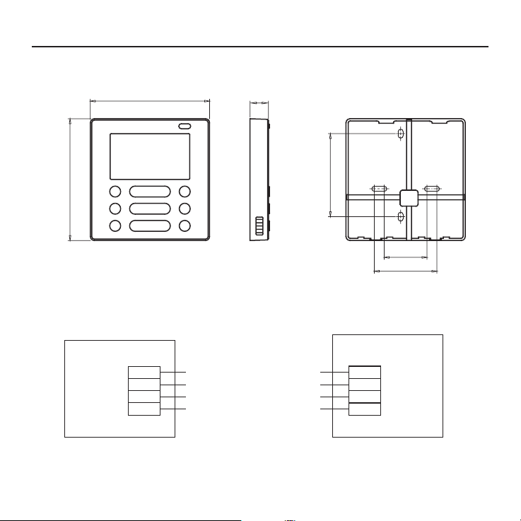
Fig 3-3
CN40
3. INSTALLATION METHOD
1 .Wired remote controller structure size gure
120
122
2.Wiring Principle Sketch:
red
black
yellow
brown
Wire controller
6
18.5
Fig 3-1
-----------------------------------
-----------------------------------
-----------------------------------
-----------------------------------
4-Core Shield Cable,
the length is decided
by installation
83.5
Insert of the
mainboard CN40
red
black
yellow
brown
Indoor unit mainboard
46
62
3.Wiring gure
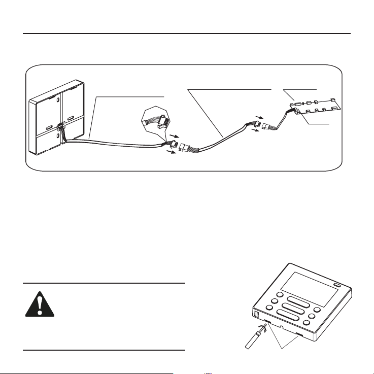
3. INSTALLATION METHOD
The connective wires group
4-core shielding wire
Mainboard
CN40
Fig 3-3
• Connect the female joint of wires group from the mainboard with the male joint of
connective wires group. (See Fig.3-3)
• Please connect the other side of connective wires group with the male joint of
wires group leads from wire controller. (See Fig.3-3)
4.Remove the upper part of wire controller
• Insert a slot screwdriver into the slots in the lower part of the wire controller (2 places),
and remove the upper part of the wire controller. (Fig.3-4)
NOTICE
The PCB is mounted in the upper
part of the wire controller. Be
careful not to damage the board
with the slot screwdriver.
Slots
7
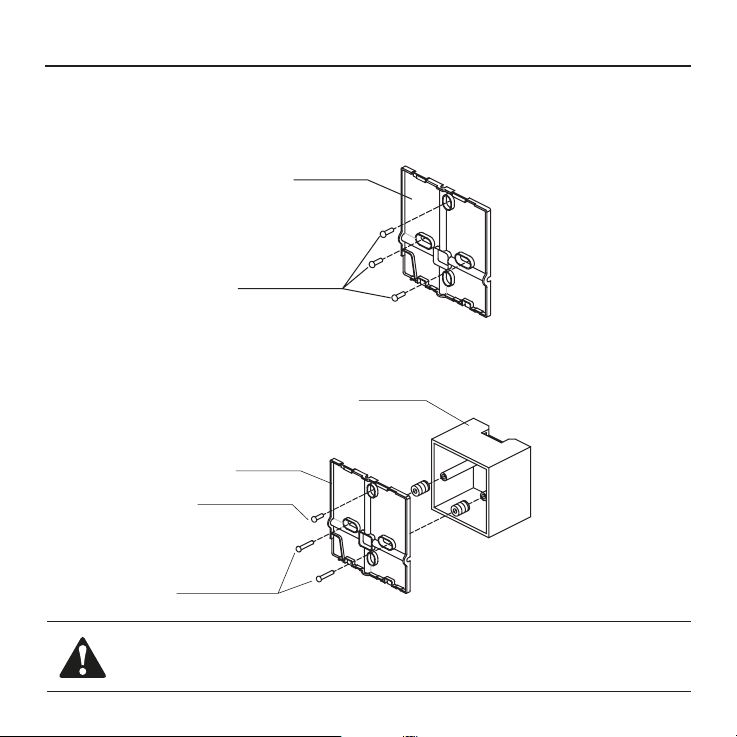
3. INSTALLATION METHOD
4. Fasten the back plate of the wire controller
• For exposed mounting, fasten the back plate on the wall with the 3 screws (M4x20) and
plugs. (Fig.3-5)
• For ush-mounting, fasten the back plate on the switch box with 2 screws (M4x25) and
fasten it on the wall with 1 screw (M4x20). (Fig.3-6)
Screws (M4x20)
Back plate
Screws (M4x20)
Fig 3-5
Switch box
Back plate
Screws (M4x25)
Fig 3-6
NOTICE
Put on a at surface. Be careful not to distort the back plate of the wire controller by overtightening the mounting screws.
8
3. INSTALLATION METHOD
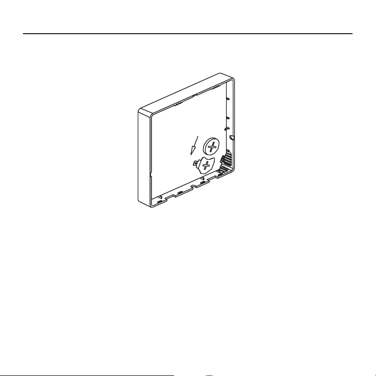
5. Battery installation
Fig 3-7
• Put the battery into the installationsite and make sure the positive side of the battery is in
accordance with the positive side of installationsite.(See Fig.3-7)
• Please set the time corrected on the rst time operation. Batteries in the wire control-
ler can timing under power failure which ensure the time keep right. When the power
restores, if the time displayed is not correct, it means the battery is dead and replace the
battery.
9

3. INSTALLATION METHOD
6. Wiring
A. For wiring in the slot, four outletting positions. There are three need cutting.
Line groove
Left side
wire outlet
Line groove
Top side
wire outlet
Bottom side
wire outlet
Right side
wire outlet
Line groove
Fig. 3-8
Cutting place
of top side wire
outlet
Cutting place
of left side wire
outlet
Cutting place
of right side
wire outlet
B.Shielded wiring
Embedded
switch box wiring
Wiring hole
Fig. 3-9 Fig. 3-10
Wiring through the wall
Wall hole and wiring hole Diameter of
wall hole: Φ20mm
Putty
Trap
Putty
Trap
CAUTION
Avoid the water enter into the wired remote controller, use trap and putty to seal the connectors of wires during wiring installation. (Fig.3-10)
When under installation, reserve certain length of the connecting wire for convenient to
take down the wired remote controller while during maintenance.
10
Putty
Trap
3. INSTALLATION METHOD
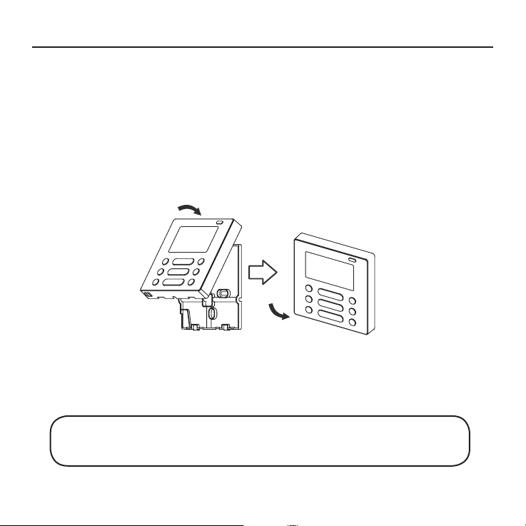
7.Reattach the upper part of the wire controller
• After adjusting the upper case and then buckle the upper case; avoid clamping the
wiring during installation. (Fig 3-11)
Fig. 3-11
All the pictures in this manual are for explanation purpose only.
Your wire controller may be slightly different. The actual shape shall prevail.
11

4. SPECIFICATION
Input voltage DC 5V/DC 12V
Ambient temperature
-5~43°C (23~110°F)
Ambient humidity RH40%~RH90%
12

swing
5. FEATURE AND FUNCTION OF THE WIRED CONTROLLER
Feature:
LCD display.
Malfunction code display: it can display the
error code, helpful for service.
4-way wire layout design, no raised part
at backside, more convenient to place the
wires and install the device.
Room temperature display.
swing
Weekly Timer.
Dimension:
HxWxD(mm) 122x120x18.5
Function:
Mode: choose Auto-Cool-Dry- Heat -Fan
Fan speed: Auto/Low/Med/High speed
Vertical swing & Horizontal swing(on some
models)
Timer ON/OFF Temp, setting Weekly timer
Follow Me Child Lock
PTC heater (on some models)
LCD display Clock
Infrared remote receiver (on some models)
Lifting panel (on some models)
13
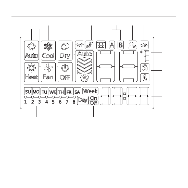
6. NAME ON THE LCD OF THE WIRE CONTROLLER
123457
10
11
15 14
68
9
12
13
1. Operation mode indication
2. Fan speed indication
3. Left-right swing indication
4. Up-down swing indication
5. Faceplate function indication
6. Main unit and secondary unit indication
7. Follow me function indication
8. PTC function indication
14
9. C°/F° indication
10. Temperature display
11. Lock indication
12. Room temperature indication
13. Clock display
14. On/Off timer
15. Timer display
56
10
11
13
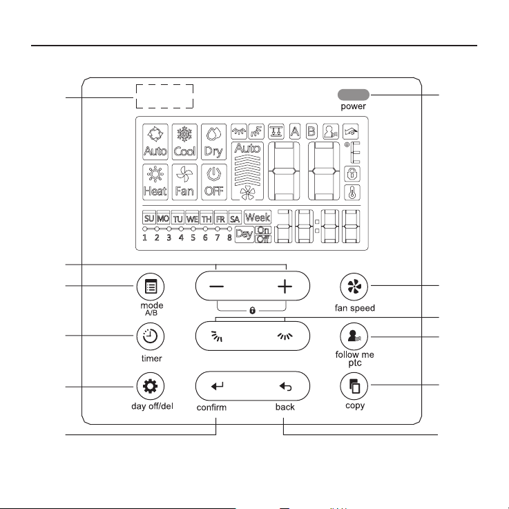
7. NAME OF THE BUTTON ON THE WIRE CONTROLLER
1
3
2
4
8
swing
9
swing
7
12
15

7. NAME OF THE BUTTON ON THE WIRE CONTROLLER
1. Power Button
2. Mode(A/B) Button
3. Adjust Button
4. Fan speed Button
5. Up-down Airow Direction and Swing Button
6. Left-right Airow Swing Button
7. Follow me(PTC) Button
8. Tinner Button
9. Day off(Del) Button
10. Conrm Button
11. Back Button
12. Copy Button
13. Infrared remote receiver (on some models)
16
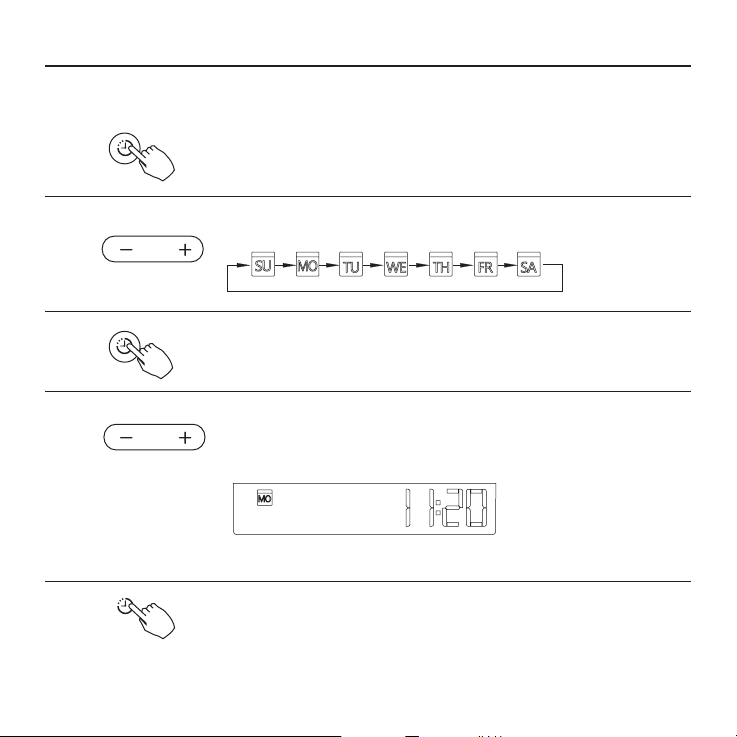
Set the current day and time
Press the Timer button for 3 seconds
1
2
timer
or more. The timer display will ash.
Press the button” + “or” - “to set the date.The
selected date will ash.
8. PREPARATORY OPERATION
3
4
5
timer
timer
The date setting is nished and the time setting is prepared after
pressing Timer button or there is no pressing button in 10 seconds.
Press the button “+”or”-”to set the current time.
Press repeatedly to adjust the current time in 1 -minute
increments.
Press and hold to adjust the current time continuous.
ex.Monday AM 11:20
The setting is done after pressing Timer button or there is no
pressing button in 10 seconds.
17
9. OPERATION
Remote signal receiving function
The wired remote controller can be a remote signal receiving device, you can use the
wireless remote controller to control the air-conditioner through the wired remote controller when the system have been powered on.
To start/stop operation
Press the Power button.
power
Operation lamp
Air conditioner ON :Lit brightly
Air conditioner OFFiNot lit
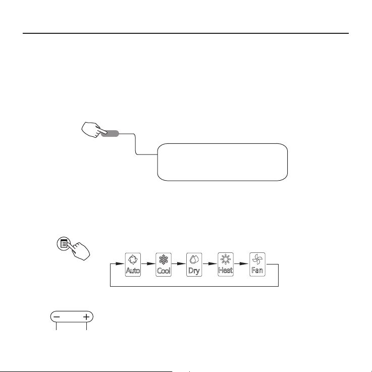
To set the operation mode
Operation mode setting
Press the Mode button to set the operation mode. (Heat
function is invalid for cool only type unit)
Mode A/B
Room temperature setting
Press the button” + “or” - “to set the room temperature.
Indoor Setting Temperature Range: 17~30°C (62~86°F)
18
Lower Rise
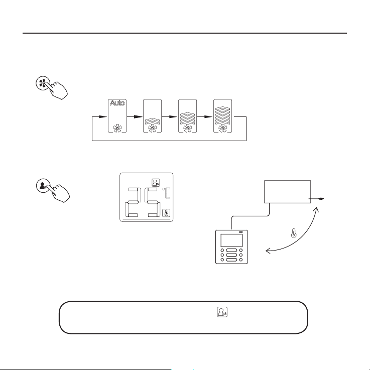
Fan speed setting
Press the Fan speed button to set the fan speed.
(This button is unavailable when in the mode of Auto or Dry)
fan speed
Room temperature sensor selection
9. OPERATION
follow
me ptc
Press the Follow me/PTC button to select
whether the room temperature is detected at
the indoor unit or the wire controller.
When the Follow me function indication appears the room
temperature is detected at the wire controller.
Indoor Unit
19
9. OPERATION
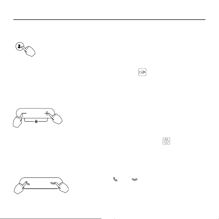
PTC function (on some models)
Press the Follow me/PTC button for 2 seconds or more to activate the
PTC function,when the unit is under the Heat mode.
Press the buttons again for 2 seconds or more to deactivate the PTC
follow me ptc
function.
When the PTC function is activated,the mark appears.(Not applicable to all the models)
Child lock function
Press and hold “+” and “-“ buttons together for 3 seconds or
more to activate the child lock function and lock all buttons on
the wire controller.
Press the buttons again for 3 seconds or more to deactivate the
child lock function.
When the child lock function is activated,the mark appears.
°C & °F scale selection (on some models)
Press and hold and buttons together for 3
seconds will alternate the temperature display between
the °C&°F scale.
20
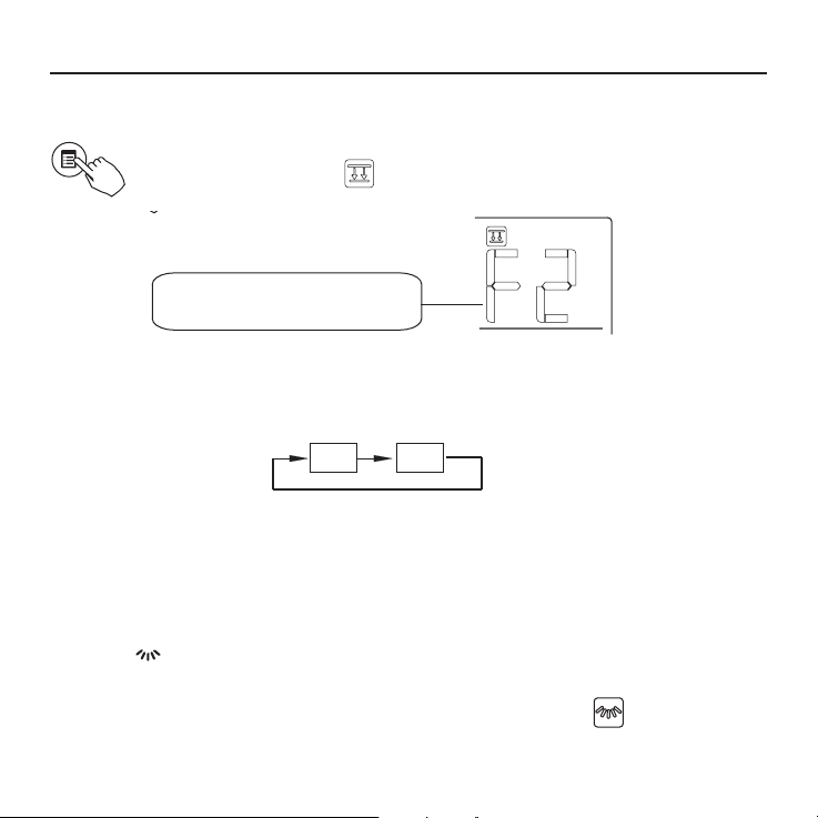
Faceplate function (on some models)
1. When the unit is off, Press the Mode(A/B) button long to activate the
faceplate function.The mark will ash.
Mode A/B
The F2 mark appears when
the faceplate is adjusted.
2. Push the Mode(A/B) button to select Unit A or Unit B, the wire controller select in a sequence that goes from(this step do not need to perform if the wire
controller is connected with one unit only):
A B
3. Press the button “+”and to control the lift and drop of the faceplate.
Pressing the “+” button can stop the face plate, while it is dropping.
Pressing the button can stop the faceplate, while it is lifting.
Left-right airow swing (on some models)
9. OPERATION
Press the button to activate the auto Left-right swing feature of the louver.
And then the louver would swing automatically. Press it again to stop.
When the auto Left-right swing feature of the louver is activated, the mark appears.
(Not applicable to all the models)
21
9. OPERATION
Up-Down airow direction and swing (on some models)
• Use button to adjust the Up-down airow direction.
1. When press the button once and quickly ,the Up-down airow direction setting feature
of the louver is activated. The moving angle of the louver is 6° for each press. Keep
pressing the button to move the louver to the desired position.
2. lf press the button long/the auto Up-down swing feature of the louver is activated. The
louver would swing automatically. Press it again to stop.
When the auto Up-down swing feature of the louver is activated, the mark appears.
(Not applicable to all the models)
• The operation can refer to the following instructions for the unit with four Up-down lou-
vers can be operated individually.
1. Press the button to activate the Up-down adjusting louver function.
The mark will ash.(Not applicable to all the models)
2. Push the Mode(A/B) button to select Unit A or Unit B, the wire controller select in
a sequence that goes from(this step do not need to perform if the wire controller is
connected with one unit only):
3. Pressing the button “+” and can select the movement of four louvers. Each time you
push the button, the wire controller select in a sequence that goes from:(the icon
means the four louvers move at the same time.)
-0
-0
-1
-3
-2
-4
A B
4. And then use button to adjust the Up-down airow direction of the selected louver.
22
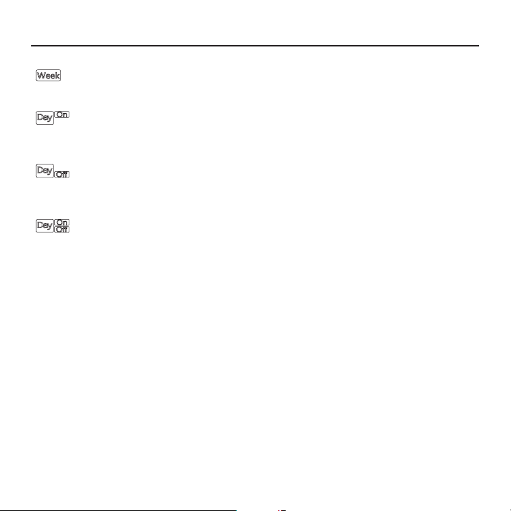
10.TIMER FUNCTIONS
WEEKLY timer
Use this timer function to set operating times for each day of the week.
On timer
Use this timer function to start air conditioner operation. The timer operates and air conditioner operation starts after the time has passed.
Off timer
Use this timer function to stop air conditioner operation. The timer operates and air conditioner operation stops after the time has passed.
On and Off timer
Use this timer function to start and stop air conditioner operation. The
timer operates and air conditioner operation starts and stops after the
time has passed.
23

10.TIMER FUNCTIONS
To set the On or Off TIMER
1
Press the Timer button to select the
timer
2
No display
Press the Conrm button and the Clock display is
ashing.
conrm
3
ex.Off timer set at PM 6:00
Press the button “ + “or” - “to set the time. After the time is set, the timer will start
or stop automatically.
Press the Conrm button again to nish the settings.
4
conrm
24
To set the On and Off TIMER
10.TIMER FUNCTIONS
1
timer
2
3
Press the button” + “or” - “to set the time of On timer, and then press the Conrm
button to conrm the setting.
Press the Timer button to select the
Press the Conrm button and the Clock display is
ashing.
conrm
conrm
Press the button” + “or” - “to set the time of Off timer.
4
5
conrm
Press the Conrm button to nish the settings.
conrm
25
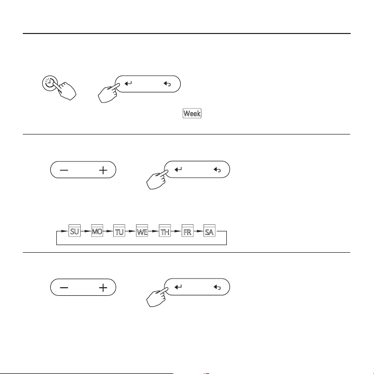
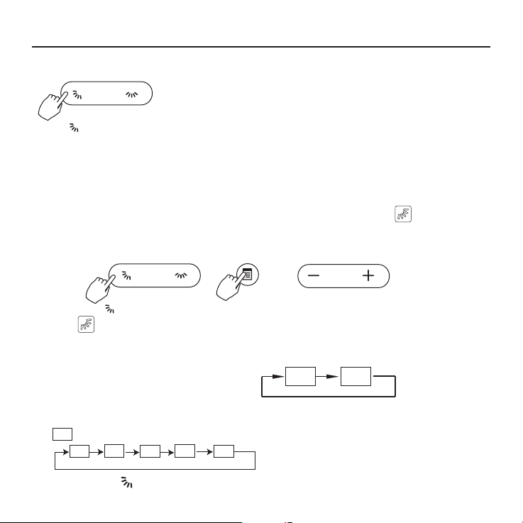
11. WEEKLY TIMER
Weekly timer setting
1
timer
Press the Timer button to select the and then press the
Conrm button to
Day of the week setting
conrm
2
conrm
Press the button” + “and” - “to select the day of the weekend then press the
CONFIRM button to conrm the setting.
Time scale setting
3
conrm
Press the button” + “and” - “to select the setting time. The setting time, mode,
temperature and fan speed will be shown on the LCD, Press the Conrm button
to enter the setting-time process.
26

Up to 8 time scales can be setted
in one day. Mode, temperature and
fan speed in different time scale
can be setted.
ex. Tuesday time scale 1
Time setting
4
conrm
Press the button” + “and” - “to set the time and then press the Conrm
button to conrm the setting.
Operation mode setting
5
conrm
Press the button” + “and” - “to set the operation mode .and then press the
Conrm button to conrm the setting.
Room temperature setting
6
11. WEEKLY TIMER
conrm
27
11. WEEKLY TIMER
Press the button “ + “and “ - “to set the room temperature .and then press the Conrm
button to conrm the setting.
NOTE:This setting is unavailable when in the mode of Fan or Off.
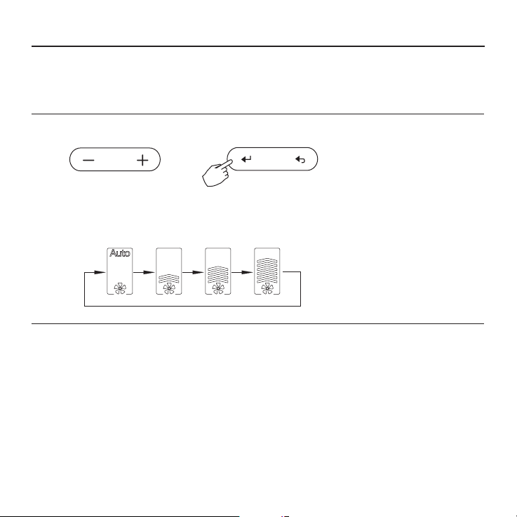
Fan speed setting
7
conrm
Press the button” + “and “-”to set the fan speed .and then press the Conrm
button to conrm the setting.
NOTE: This setting is unavailable when in the mode of Auto, Dry or Off
Different time scales can be setted by repeating step 3 to 7
8
Other days in one week can be setted by repeating step 3 to 8.
9
NOTE:
The weekly timer setting can be returned to the previous step by pressing Back button.
The current setting will be restored and withdrawn the weekly timer setting automatically when there is no operation
for 30 seconds.
28

WEEKLY timer operation
11. WEEKLY TIMER
• To start
timer
• To cancel
power
timer
Press the Timer button to select the and the timer
starts automatically.
Press the Power button to cancel the timer mode.
The timer mode can also be canceled by changing the
timer mode using the Timer button.
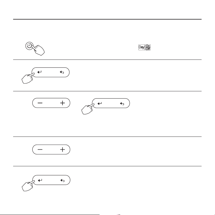
To set the DAY OFF (for a holiday)
During the weekly timer, press the Conrm button to
1
conrm
2
set the day.
Press the button “ + ” and “ - ” to select the day to set
the DAY OFF.
29

11. WEEKLY TIMER
3
day off/on
4
The DAY OFF can be setted for other days by repeating the steps 2 and 3.
5
back
• To cancel: Follow the same procedures as those for setup
• Notes: The DAY OFF setting is cancelled automatically after the set day has passed.
Copy out the setting in one day into the other day.
A reservation made once can be copied to another day of the week.
The whole reservation of the selected day of the week will be copied.
The effective use of the copy mode ensures ease of making reservations.
1
conrm
2
30
Press the Day off button to set the DAY OFF.
The mark is hidden
ex. The DAY OFF is set for Wednesday
Press the Back button to back to the weekly tinner.
During the weekly timer, press the Conrm button.
Press the button” + “and” - “to select the day to copy from.

11. WEEKLY TIMER
3
copy
4
5
copy
The mark ashes quickly
Other days can be copied by repeating step 4 and 5.
6
7
conrm
8
back
Press the Copy button, the letter “CY” will be shown on the
LCD.t
Press the button” + “and” - “to select the day to copy to.
Press the Copy button to conrm .
Press the Conrm button to conrm the settings.
Press the Back button to back to the weekly timer.
ex. Copy the setting of Monday to Wednesday
31

11. WEEKLY TIMER
Delete the time scale in one day.
1
conrm
During the weekly timer, press the Conrm button.
2
conrm
Press the button” + “and” -” to select the day of the weekend then press the Conrm
button to conrm the setting.
3
Press the button” + “and” - “to select the setting time want to be deleted.
The setting time, mode, temperature and fan speed will be shown on the LCD.
The setting time, mode, temperature and fan speed can be deleted by pressing
the Day off(Del) button.
32
day off/del
ex. Delete the time scale 1 on Saturday

12. FAULT ALARM HANDING
If the system does not properly operate except the above mentioned cases or the
above mentioned malfunctions is evident, investigate the system according to the
following procedures.
MALFUNCTION & PROTECTION
No.
DEFINE
Error of communication between wire
1
controler and indoor unit
DISPLAY DIGITAL TUBE
F0
2 The faceplate is abnormal F1
Please check the error display of indoor unit and read “OWNER’S MANUAL” if other error
code appears.
13.TECHNICAL INDICATION AND REQUIREMENT
EMC and EMI comply with the CE certication requirements.
33


• Στο παρόν εγχειρίδιο θα βρείτε αναλυτικές
οδηγίες σχετικά με όλα όσα πρέπει να
προσέξετε κατά τη λειτουργία.
• Για την ορθή λειτουργία του ενσύρματου
τηλεχειριστηρίου διαβάστε προσεκτικά το
παρόν εγχειρίδιο πριν τη χρήση.
• Φυλάξτε το παρόν εγχειρίδιο για μελλοντική
αναφορά.

ΠΕΡΙΕΧΟΜΕΝΑ
1. ΟΔΗΓΙΕΣ ΑΣΦΑΛΕΙΑΣ ....................................................................3
2. ΠΑΡΕΛΚΟΜΕΝΑ ΕΓΚΑΤΑΣΤΑΣΗΣ.................................................4
3. ΜΕΘΟΔΟΛΟΓΙΑ ΕΓΚΑΤΑΣΤΑΣΗΣ ...................................................6
4. ΤΕΧΝΙΚΑ ΧΑΡΑΚΤΗΡΙΣΤΙΚΑ .........................................................12
5. ΙΔΙΟΤΗΤΕΣ ΚΑΙ ΛΕΙΤΟΥΡΓΙΕΣ ΤΟΥ ΤΗΛΕΧΕΙΡΙΣΤΗΡΙΟΥ ..........13
6. ΟΝΟΜΑΤΟΛΟΓΙΑ ΕΝΔΕΙΞΕΩΝ ΣΤΗΝ ΟΘΟΝΗ LCD ΤΟΥ
ΤΗΛΕΧΕΙΡΙΣΤΗΡΙΟΥ ....................................................................14
7. ΠΕΡΙΓΡΑΦΗ ΤΩΝ ΠΛΗΚΤΡΩΝ ΣΤΟ ΕΝΣΥΡΜΑΤΟ ΧΕΙΡΙΣΤΗΡΙΟ 15
8. ΕΝΑΡΞΗ ΛΕΙΤΟΥΡΓΙΑΣ ................................................................17
9. ΛΕΙΤΟΥΡΓΙΑ ..................................................................................18
10. ΛΕΙΤΟΥΡΓΙΕΣ ΧΡΟΝΟΔΙΑΚΟΠΤΗ ................................................23
11. ΕΒΔΟΜΑΔΙΑΙΟΣ ΧΡΟΝΟΔΙΑΚΟΠΤΗΣ .........................................26
12. ΠΙΝΑΚΑΣ ΠΡΟΒΛΗΜΑΤΩΝ ..........................................................33
13. ΤΕΧΝΙΚΕΣ ΠΡΟΔΙΑΓΡΑΦΕΣ .........................................................33

1. ΟΔΗΓΙΕΣ ΑΣΦΑΛΕΙΑΣ
• Διαβάστε προσεκτικά τις οδηγίες ασφαλείας πριν την εγκατάσταση της μονάδας.
• Βεβαιωθείτε πως έχετε κατανοήσω πλήρως τα παρακάτω, για την ασφαλή λειτουργία της
μονάδας.
ΠΡΟΕΙΔΟΠΟΙΗΣΗ
ΠΡΟΣΟΧΗ
Η εσφαλμένη χρήση μπορεί να οδηγήσει σε θάνατο ή σε
σοβαρούς τραυματισμούς.
Η εσφαλμένη χρήση μπορεί να οδηγήσει σε τραυματισμούς ή
φθορά περιουσίας.
ΠΡΟΕΙΔΟΠΟΙΗΣΗ
Η εγκατάσταση και επανεγκατάσταση της μονάδας θα πρέπει να πραγματοποιείται από
εξειδικευμένο προσωπικό.
Λανθασμένη εγκατάσταση μπορεί να προκαλέσει πυρκαγιά, ηλεκτροπληξία, τραυματισμό ή
διαρροή νερού.
Ανατρέξτε στο παρόν εγχειρίδιο.
Μην εγκαθιστάτε τη μονάδα παραβλέποντας τις σχετικές οδηγίες.
ΣΗΜΕΙΩΣΗ
- Μην εγκαθιστάτε τη μονάδα σε μέρος με πιθανότητα διαρροής ή εύφλεκτων αερίων.
Σε περίπτωση που διαρρεύσουν εύφλεκτα αέρια δεν απομακρυνθούν από το
τηλεχειριστήριο, μπορεί να προκαλέσουν πυρκαγιά.
- Μην λειτουργείτε τη μονάδα με βρεγμένα χέρια και μην αφήνετε νερό να εισέλθει στο
τηλεχειριστήριο. Σε αντίθετη περίπτωση μπορεί να προκληθεί ηλεκτροπληξία.
- Η καλωδίωση θα πρέπει να συμφωνεί με τη τάση ρεύματος του τηλεχειριστηρίου.
Διαφορετικά μπορεί να προκληθεί υπερθέρμανση και πυρκαγιά.
- Θα πρέπει να προσαρμοστούν ειδικά καλώδια. Δεν θα πρέπει να ασκείται εξωτερική
πίεση στα καλώδια για την αποφυγή φθοράς τους, καθώς υπάρχει πιθανότητα
υπερθέρμανσης και πυρκαγιάς.
3

2. ΕΞΑΡΤΗΜΑΤΑ ΕΓΚΑΤΑΣΤΑΣΗΣ
Επιλέξτε τοποθεσία εγκατάστασης
Μην εγκαθιστάτε σε μέρη με έντονη ύπαρξη στοιχείων όπως λαδιού, ατμού ή διοξείδιο
του θείου, διαφορετικά μπορεί να μειωθεί η απόδοση της συσκευής και να παρουσιάσει
δυσλειτουργίες.
Προετοιμασία πριν από την εγκατάσταση
1. Παρακαλούμε βεβαιώστε ότι έχετε προμηθευτεί τα ακόλουθα.
No. Ονομασία Qty. Παρατηρήσεις
1 Τηλεχειριστήριο 1
Εγχειρίδιο χρήσης και
2
εγκατάστασης
3 Βίδες 3 Μ4Χ20 (για τη στήριξη στον τοίχο)
4 Ούπα 3 Για την στήριξη στον τοίχο
5 Βίδες 2
6 Πλαστικές μπάρες βιδών 2 Για προσαρμογή στο ηλεκτρολογικό κουτί
7 Ο συλλέκτης καλωδίων 1 Προεραιτικό
2. Προετοιμάστε τα ακόλουθα στον χώρο.
1
Μ4Χ25 (για εγκατάσταση στο
ηλεκτρολογικό κουτί)
No. Όνομα
1 ηλεκτρολογικό κουτί 1
Ηλεκτρολογικός σωλήνας
2
(Μόνωση και σφιγκτήρες)
4
Ποσότητες
(τοποθέτηση
εντός του τοίχου)
1
Προδιαγραφές
(μόνο για αναφορά)
Παρατηρήσεις

2. ΕΞΑΡΤΗΜΑΤΑ ΕΓΚΑΤΑΣΤΑΣΗΣ
Προφυλάξεις κατά την εγκατάσταση
1. Αυτό το εγχειρίδιο παρέχει πληροφορίες σχετικά με την εγκατάσταση του
τηλεχειριστήριου. Παρακαλούμε ανατρέξτε στο ηλεκτρολογικό διάγραμμα για την
εγκατάσταση με την εσωτερική μονάδα.
2. Το χειριστήριο δέχεται μικρή τάση. Απαγορεύεται η σύνδεση του με καλώδιο με
τάση 220V ή με καλώδιο υψηλής τάσης 380V. Η απόσταση από τέτοια καλώδια θα
πρέπει να είναι μεταξύ 300mm~500mm ή μεγαλύτερη.
3. Το θωρακισμένο καλώδιο του χειριστηρίου πρέπει να γειωθεί σωστά.
4. Μετά την σύνδεση του χειριστηρίου μην χρησιμοποιείτε μετρητή γείωσης &
μόνωσης (μέγγερ) για να ελέγξετε την μόνωση.
5. Το καλώδιο σύνδεσης του χειριστηρίου δεν πρέπει να είναι μεγαλύτερο από 20m.
5

Fig 3-3
CN40
3. ΜΕΘΟΔΟΛΟΓΙΑ ΕΓΚΑΤΑΣΤΑΣΗΣ
1. Διαστάσεις ενσύρματου χειριστηρίου
120
122
2. Σκαρήφημα Συνδεσμολογίας
Κόκκινο
μαύρο
κίτρινο
καφέ
Ενσύρματο χειριστήριο
6
-----------------------------------
-----------------------------------
-----------------------------------
-----------------------------------
18.5
Εικ. 3-1
Fig 3-1
4- 5-κλωνο θωρακισμένο καλώδιο,
το μήκος του οποίου ορίζεται κατά
την εγκατάσταση
Εικ. 3-2
83.5
46
62
Δίοδος στην οθόνη
εσωτερικής μονάδας
Κόκκινο
μαύρο
κίτρινο
καφέ
Οθόνη εσωτερικής μονάδας

3. Σχηματική Αναπαράσταση σύνδεσης
3. ΜΕΘΟΔΟΛΟΓΙΑ ΕΓΚΑΤΑΣΤΑΣΗΣ
Καλώδια σύνδεσης
4-κλωνο καλώδιο
Οθόνη εσωτερικής
μονάδας
CN40
Εικ. 3-3
Fig 3-3
• Συνδέστε την θηλυκή επαφή της πλακέτας με την αρσενική επαφή του καλωδίου
σύνδεσης (Βλ. Εικ. 3-3)
• Συνδέστε την άλλη επαφή του καλωδίου σύνδεσης με την αρσενική επαφή του
ενσύρματου χειριστηρίου (Βλ. Εικ. 3-3)
4.Αφαιρέστε το πάνω μέρος του ενσύρματου χειριστηρίου
• Εισάγετε ένα ίσιο κατσαβίδι στις 2 σχισμές που υπάρχουν στο κάτω μέρος του
ενσύρματου χειριστηρίου (2 μέρη) και αφαιρέστε το πάνω μέρος του. (Εικ. 3-4)
ΣΗΜΕΙOΣΗ
Η πλακέτα βρίσκεται στο πάνω μέρος του
ενσύρματου χειριστηρίου. Δώστε ιδιαίτερη
προσοχή ώστε να μην προκαλέσετε
φθορά στην πλακέτα με το κατσαβίδι.
Σχισμές
Εικ. 3-4
7

3. ΜΕΘΟΔΟΛΟΓΙΑ ΕΓΚΑΤΑΣΤΑΣΗΣ
4. Τοποθετήστε την βάση του ενσύρματου χειριστηρίου
• Για εξωτερική τοποθέτηση, στερεώστε την βάση στον τοίχο με 3 βίδες (Μ4Χ20) και ούπα
(Εικ. 3-5)
• Για χωνευτή τοποθέτηση, στερεώστε την βάση στο ηλεκτρολογικό κουτί με 2 βίδες
(Μ4Χ25) και έπειτα στερεώστε στον τοίχο με 1 βίδα (Μ4Χ20). (Εικ. 3-6)
Βίδα (M4×20)
Βάση
Βίδες (M4×20)
Εικ. 3-5
Ηλεκτρολογικό κουτί
Βάση
Βίδες (M4×25)
Εικ. 3-6
ΣΗΜΕΙΩΣΗ
Τοποθετήστε το σε επίπεδη επιφάνεια. Μην σφίξετε υπερβολικά τις βίδες στήριξης.
8

3. ΜΕΘΟΔΟΛΟΓΙΑ ΕΓΚΑΤΑΣΤΑΣΗΣ
5. Εγκατάσταση Μπαταρίας
Εικ. 3-7
• Τοποθετήστε την μπαταρία στη περιοχή εγκατάστασης και βεβαιωθείτε ότι έχετε λάβει
υπόψη την θετική πλευρά της μπαταρίας αντίστοιχα με την σήμανση στο χειριστήριο.
(Εικ. 3-7)
• Ρυθμίστε την ώρα κατά την πρώτη εκκίνηση. Με τη χρήση των μπαταριών εξασφαλίζεται
η διατήρηση της ρυθμισμένης ώρας κατά την επανεκκίνηση έπειτα από διακοπή
ρεύματος. Αν η ώρα δεν είναι η σωστή, παρακαλούμε αντικαταστήστε τις μπαταρίες.
9

3. ΜΕΘΟΔΟΛΟΓΙΑ ΕΓΚΑΤΑΣΤΑΣΗΣ
6. Συνδεσμολογία
A. Εξωτερική τοποθέτηση, 4 θέσεις εξόδου.
Απαιτείται να κόψετε σε 3 σημεία
Αριστερή
Έξοδος
καλωδίου
Γραμμή
Εγκοπής
Γραμμή
Εγκοπής
Γραμμή
Εγκοπής
Έξοδος
καλωδίου
Δεξιά Έξοδος
καλωδίου
Κάτω Έξοδος
καλωδίου
Γραμμή
Εγκοπής
Εικ. 3-8
Σημείο κοπής
στην πάνω
πλευρά εξόδου
του καλωδίου
Σημείο κοπής
στην αριστερή
πλευρά εξόδου
του καλωδίου
Σημείο κοπής
στην δεξιά
πλευρά εξόδου
του καλωδίου
B. Χωνευτή τοποθέτηση
Εισάγετε στον τοίχο το
ηλεκτρολογικό κουτί
Οπή οδήγησης καλωδίου Οπή στον τοίχο καθώς και οπή
Εικ 3-9 Εικ. 3-10
Καλώδια εντός του τοίχου
οδήγησης του καλωδίου. Διάμετρος
οπής στον τοίχο: Φ20mm
Στόκος
Παγίδα
Στόκος
Παγίδα
ΠΡΟΣΟΧΗ
Αποφύγετε εισροή νερού στο ενσύρματο χειριστήριο και χρησιμοποιήστε στόκο για να
καλύψετε τις επαφές των καλωδίων κατά την εγκατάσταση (Εικ. 3-9). Βεβαιωθείτε πως
έχετε αφήσει επαρκές ελεύθερο καλώδιο, διότι κατά τη διάρκεια εργασιών συντήρησης
μπορεί να χρειαστεί να ξεμοντάρετε το ενσύρματο χειριστήριο.
10
Στόκος
Παγίδα

3. ΜΕΘΟΔΟΛΟΓΙΑ ΕΓΚΑΤΑΣΤΑΣΗΣ
7.Προσαρμόστε το πάνω μέρος του τηλεχειριστηρίου
• Αφότου προσαρμόσετε το πάνω μέρος αποφύγετε κατά την εγκατάσταση τη σύσφιξη
και τον εγκλωβισμό της συνδεσμολογίας. (Εικ. 3-11)
Εικ. 3-11
Fig. 3-11
Όλες οι εικόνες του εγχειριδίου είναι αναφορικές. Το τηλεχειριστήριο που
προμηθευτήκατε μπορεί να διαφέρει. Παρακαλούμε ανατρέξτε στο πραγματικό μοντέλο.
11

4. ΤΕΧΝΙΚΑ ΧΑΡΑΚΤΗΡΙΣΤΙΚΑ
Παροχή ρεύματος: DC 5V/DC 12V
Θερμοκρασιακά εύρη λειτουργίας
-5~43°C (23~110°F)
Εύρος σχετικής υγρασίας RH40%~RH90%
12

swing
Διαστάσεις:
HxWxD(mm) 122x120x18.5
5. ΙΔΙΟΤΗΤΕΣ ΚΑΙ ΛΕΙΤΟΥΡΓΙΕΣ ΤΟΥ ΤΗΛΕΧΕΙΡΙΣΤΗΡΙΟΥ
Περιγραφές:
Οθόνη LCD
Κωδικός σφάλματος: εμφανίζεται
προειδοποιώντας για σφάλμα κατά τη λειτουργία.
4-κλωνο θωρακισμένο καλώδιο ειδικού
σχεδιασμού για εύκολη εγκατάσταση
Ένδειξη θερμοκρασίας χώρου.
Εβδομαδιαίος Χρονοδιακόπτης
swing
Λειτουργία:
Κατάσταση: επιλέξτε Auto- Cool- Dry- Heat- Fan
Ταχύτητα Ανεμιστήρα: Auto/Low/Med/High speed
Κάθετη & Οριζόντια κίνηση (σε ορισμένα μοντέλα)
Χρονοδιακόπτης ON/OFF
Ρύθμιση θερμοκρασίας
Εβδομαδιαίος χρονοδιακόπτης
Follow Me
Παιδικό κλείδωμα
PTC αντίσταση (σε ορισμένα μοντέλα)
LDC οθόνη
Ρολόι
Υπέρυθρες (σε ορισμένα μοντέλα)
Ανασηκωμένο πάνελ (σε ορισμένα μοντέλα)
13

6. ΟΝΟΜΑΤΟΛΟΓΙΑ ΕΝΔΕΙΞΕΩΝ ΣΤΗΝ ΟΘΟΝΗ LCD ΤΟΥ ΤΗΛΕΧΕΙΡΙΣΤΗΡΙΟΥ
123457
10
11
15 14
68
9
12
13
1. Ένδειξη λειτουργίας
2. Ένδειξη ταχύτητας ανεμιστήρα
3. Ένδειξη Αριστερής – Δεξιάς κίνησης
4. Ένδειξη Πάνω- Κάτω κίνησης
5. Ένδειξη λειτουργίας «Faceplate»
6. Ένδειξη της κυρίως και της βοηθητικής
μονάδας
7. Ένδειξη της λειτουργίας Follow me
14
8. Ένδειξη λειτουργίας PTC
9. Ένδειξη C° / F°
10. Ένδειξη θερμοκρασίας
11. Ένδειξη κλειδώματος
12. Ένδειξη θερμοκρασίας δωματίου
13. Ένδειξη ρολογιού
14. On/Off χρονοδιακόπτη
15. Ένδειξη Χρονοδιακόπτη

56
10
11
13
7. ΠΕΡΙΓΡΑΦΗ ΤΩΝ ΠΛΗΚΤΡΩΝ ΣΤΟ ΕΝΣΥΡΜΑΤΟ ΧΕΙΡΙΣΤΗΡΙΟ
1
3
2
4
8
swing
9
swing
7
12
15

7. ΠΕΡΙΓΡΑΦΗ ΤΩΝ ΠΛΗΚΤΡΩΝ ΣΤΟ ΕΝΣΥΡΜΑΤΟ ΧΕΙΡΙΣΤΗΡΙΟ
1. Πλήκτρο Ενεργοποίησης
2. Πλήκτρο κατάστασης (Α/Β)
3. Πλήκτρο προσαρμογής
4. Πλήκτρο ταχύτητας ανεμιστήρα
5. Κατεύθυνση ανεμιστήρα Πάνω – Κάτω και Πλήκτρο Κίνησης
6. Πλήκτρο Αριστερής-δεξιάς κίνησης αέρα
7. Πλήκτρο Follow me (PTC)
8. Πλήκτρο Χρονοδιακόπτη
9. Πλήκτρο DAY off (Διαγραφή)
10. Πλήκτρο βεβαίωσης
11. Πλήκτρο Επιστροφής
12. Πλήκτρο Αντιγραφής
13. Υπέρυθρες (σε ορισμένα μοντέλα)
16

Ρυθμίστε την συγκεκριμένη μέρα και ώρα
Πιέστε το πλήκτρο Χρονοδιακόπτη για 3 δευτερόλεπτα ή
1
Χρονοδιακόπτης
2
περισσότερο. Θα αναβοσβήσει η ένδειξη του χρονοδιακόπτη.
Πιέστε το πλήκτρο «+» ή «-» για να ρυθμίσετε την ημέρα.
Η επιλεγμένη ημέρα θα αναβοσβήσει.
8. ΕΝΑΡΞΗ ΛΕΙΤΟΥΡΓΙΑΣ
3
4
5
Χρονοδιακόπτης
Χρονοδιακόπτης
Η ρύθμιση της θερμοκρασίας έχει ολοκληρωθεί και η ρύθμιση του
χρονοδιακόπτη είναι ενεργή μόλις πιέσετε το πλήκτρο Χρονοδιακόπτη
για 10 δευτερόλεπτα.
Πατήστε το πλήκτρο «+» ή «-» για να ρυθμίσετε την ώρα.
Πατήστε επανειλημμένα για να προσαρμόσετε την ώρα σε 1 λεπτό.
Πατήστε και κρατήστε παρατεταμένα για να προσαρμόσετε την ώρα.
πχ. Δευτέρα 11:20πμ
Η ρύθμιση πραγματοποιείτε μόλις πατήσετε το πλήκτρο
Χρονοδιακόπτη για 10 δευτερόλεπτα.
17

9. ΛΕΙΤΟΥΡΓΙΑ
Σήμα τηλεχειριστηρίου
Το τηλεχειριστήριο είναι μια συσκευή λήψης σήματος, όπου μπορείτε να τη
χρησιμοποιήσετε για τον έλεγχο του κλιματιστικού σας όταν αυτό τεθεί σε λειτουργία.
Λειτουργία έναρξης/ διακοπής
Πατήστε το πλήκτρο Ενεργοποίηση.
Ρεύμα
Ένδειξη λειτουργίας
Κλιματιστικό ΟΝ: Ανάβει
Κλιματιστικό OFF: Δεν ανάβει
Ρύθμιση κατάστασης λειτουργίας
Ρύθμιση λειτουργίας
Κατάσταση
(Α/Β)
Ρύθμιση θερμοκρασίας δωματίου
Lower Rise
18
Πατήστε το πλήκτρο Mode για να ρυθμίσετε την κατάσταση λειτουργίας.
(Στα μοντέλα μόνο ψύξη, δεν υπάρχει διαθέσιμη η λειτουργία της
θέρμανσης)
Πατήστε το πλήκτρο «+» ή «-» για να ρυθμίσετε τη θερμοκρασία
δωματίου. Ρύθμιση εσωτερικού Θερμοκρασιακού εύρους:
17~30°(62~86°)

Ρύθμιση Ταχύτητας ανεμιστήρα
Πατήστε το πλήκτρο Fan Speed για να ρυθμίσετε τη ταχύτητα
του ανεμιστήρα. (Αυτό το πλήκτρο δεν διατίθεται όταν είναι σε
κατάσταση Auto ή Dry)
Ταχύτητα
Ανεμιστήρα
Αισθητήρας επιλογής θερμοκρασίας δωματίου
follow
me ptc
Πατήστε το πλήκτρο Follow me/PTC για να
επιλέξετε αν η θερμοκρασία δωματίου θα
εμφανίζεται στην εσωτερική μονάδα ή στο
τηλεχειριστήριο.
Όταν εμφανίζεται η Follow me ένδειξη, η θερμοκρασία
δωματίου θα εμφανιστεί στο τηλεχειριστήριο.
9. ΛΕΙΤΟΥΡΓΙΑ
Εσωτερική
Μονάδα
19

9. ΛΕΙΤΟΥΡΓΙΑ
PTC λειτουργία ( σε ορισμένα μοντέλα)
Πατήστε το πλήκτρο Follow me/PTC για 2 δευτερόλεπτα ή περισσότερα
ώστε να ενεργοποιήσετε τη λειτουργία PTC, όταν η μονάδα βρίσκεται
σε λειτουργία θέρμανσης.
follow me ptc
Πατήστε τα πλήκτρα ξανά για 2 δευτερόλεπτα ή περισσότερα για να
απενεργοποιήσετε τη PTC λειτουργία.
Όταν ενεργοποιηθεί η λειτουργία PTC, το εμφανίζεται.
(Δεν εφαρμόζεται σε όλα τα μοντέλα)
Λειτουργία Παιδικού Κλειδώματος
Πατήστε παρατεταμένα τα πλήκτρο «+»και «-» μαζί για 3
δευτερόλεπτα ή περισσότερα ώστε να ενεργοποιήσετε τη
λειτουργία παιδικού κλειδώματος και κλειδώστε όλα τα πλήκτρα
του τηλεχειριστηρίου.
Όταν η λειτουργία παιδικού κλειδώματος ενεργοποιηθεί,
εμφανίζεται
°C & °F κλίμακα επιλογής (σε ορισμένα μοντέλα)
Πατήστε παρατεταμένα τα πλήκτρα και μαζί για
3 δευτερόλεπτα ώστε να αλλάξετε τη κλίμακα °C & °F.
20

9. ΛΕΙΤΟΥΡΓΙΑ
Faceplate λειτουργία (σε ορισμένα μοντέλα)
1. Όταν η μονάδα είναι απενεργοποιήμενη, πατήστε το πλήκτρο Mode (A/B)
ώστε να ενεργοποιήσετε τη λειτουργία Faceplate. Θα ανάψει το .
Mode A/B
To F2 σήμα εμφανίζεται όταν
προσαρμοστεί το Faceplate.
2. Πατήστε το πλήκτρο Mode (A/B) για να επιλέξετε τη μονάδα Α ή τη μονάδα
Β, όπως φαίνεται παρακάτω(αυτό το βήμα δεν χρειάζεται σε περίπτωση που
το τηλεχειριστήριο είναι συνδεδεμένο σε μια μονάδα):
A B
3. Πατήστε τα πλήκτρα «+»και «-» μαζί ώστε να ανασηκώσετε ή να κατεβάσετε
το faceplate.
Πατήστε το πλήκτρο «+» για να σταματήσετε το faceplate όταν κατεβαίνει.
Πατήστε το πλήκτρο «-» για να σταματήσετε το faceplate, όταν ανεβαίνει.
Αριστερή - δεξιά κίνηση αέρα (σε ορισμένα μοντέλα)
Πατήστε το πλήκτρο για να ενεργοποιήσετε την αυτόματη αριστερή-δεξιά κίνηση της
περσίδας. Πατήστε ξανά για να διακόψετε τη λειτουργία.
Όταν η αυτόματη λειτουργία αριστερής-δεξιάς κίνησης της περσίδας ενεργοποιηθεί, θα
εμφανιστεί το . (Δεν εφαρμόζεται σε όλα τα μοντέλα)
21

-0
9. ΛΕΙΤΟΥΡΓΙΑ
-0
Πάνω-Κάτω Κατεύθυνση του αέρα και κίνηση περσίδων (σε ορισμένα μοντέλα)
• Χρησιμοποιήστε το πλήκτρο ώστε να εφαρμόσετε την Πάνω-Κάτω κατεύθυνση του αέρα.
1. Πατώντας το πλήκτρο μια φορά και γρήγορα, η ρύθμιση της λειτουργίας Πάνω-Κάτω
κατεύθυνσης του αέρα ενεργοποιείται. Η κλίση της γωνίας είναι 6 μοίρες για κάθε πάτημα.
Πατήστε παρατεταμένα το πλήκτρο μέχρι να ρυθμιστεί η επιθυμητή γωνία της περσίδας.
2. Πατώντας το πλήκτρο παρατεταμένα, η αυτόματη Πάνω-Κάτω κίνηση της περσίδας
ενεργοποιείται. Πατήστε ξανά για να διακόψετε τη λειτουργία.
• Η λειτουργία πραγματοποιείται όπως παρακάτω στην περίπτωση 4 Πάνω- κάτω περσίδων
όπου πραγματοποιείται ξεχωριστά.
1. Πατήστε το πλήκτρο για να ενεργοποιήσετε την Πάνω-Κάτω λειτουργία της
περσίδας. Το σήμα θα αναβοσβήσει. (Δεν εφαρμόζεται σε όλα τα μοντέλα)
2. Πιέστε το πλήκτρο Mode (A/B) το τηλεχειριστήριο επιλέγει τη σειρά όπως φαίνεται
παρακάτω (αυτό το βήμα δεν χρειάζεται να ακολουθηθεί σε περίπτωση που το
τηλεχειριστήριο είναι συνδεδεμένο σε μια μονάδα):
3. Πατώντας τα πλήκτρα «+»και «-» μπορείτε να επιλέξετε τη κίνηση των 4 περσίδων.
Κάθε φορά που πατάτε το πλήκτρο, το τηλεχειριστήριο επιλέγει τη σειρά όπως
παρακάτω (το εικονίδιο σημαίνει ότι οι 4 περσίδες κινούνται ταυτόχρονα.
-0
-1
-3
-2
A B
-4
4. Η χρήση του πλήκτρου αφορά τη προσαρμογή τη Πάνω-Κάτω κατεύθυνσης του
αέρα της επιλεγμένης περσίδας.
22

10. ΛΕΙΤΟΥΡΓΙΕΣ ΧΡΟΝΟΔΙΑΚΟΠΤΗ
Εβδομαδιαίος Χρονοδιακόπτης
Χρησιμοποιήστε τη λειτουργία εβδομαδιαίου χρονοδιακόπτη για κάθε
ημέρα της εβδομάδας.
Ενεργοποίηση χρονοδιακόπτη
Χρησιμοποιήστε αυτή τη λειτουργία για να εκκινήσετε το κλιματιστικό.
Ο χρονοδιακόπτης λειτουργεί και το κλιματιστικό ενεργοποιείται μόλις ο
χρόνος περάσει.
Απενεργοποίηση χρονοδιακόπτη
Χρησιμοποιήστε αυτή τη λειτουργία για να διακόψετε τη λειτουργία
του κλιματιστικού. Ο χρονοδιακόπτης λειτουργεί και το κλιματιστικό θα
απενεργοποιηθεί μόλις ο χρόνος περάσει.
Ενεργοποίηση και απενεργοποίηση χρονοδιακόπτη
Χρησιμοποιήστε τη λειτουργία χρονοδιακόπτη για την ενεργοποίηση και
απενεργοποίηση του κλιματιστικού. Ο χρονοδιακόπτης θα λειτουργήσει
και το κλιματιστικό θα ενεργοποιηθεί και απενεργοποιηθεί μόλις ο χρόνος
περάσει.
23

10. ΛΕΙΤΟΥΡΓΙΕΣ ΧΡΟΝΟΔΙΑΚΟΠΤΗ
Ρύθμιση Χρονοδιακόπτη ON ή OFF
Πατήστε το πλήκτρο χρονοδιακόπτη
1
χρονοδιακόπτης
για να επιλέξετε
No display
2
επιβεβαίωση
Πατήστε το πλήκτρο Επιβεβαίωσης και το ρολόι θα
ανάψει.
3
πχ. Ρύθμιση απενεργοποίησης
χρονοδιακόπτη στις 6:00μμ
Πατήστε το πλήκτρο «+» ή «-» για να ρυθμίσετε την ώρα. Αφότου
πραγματοποιηθεί η ρύθμιση ο χρονοδιακόπτης θα αρχίσει ή θα
σταματήσει αυτόματα.
4
επιβεβαίωση
24
Πατήστε το πλήκτρο Επιβεβαίωσης ξανά για να
ολοκληρώσετε τη ρύθμιση.

Ενεργοποίηση Χρονοδιακόπτη ON και OFF
10. ΛΕΙΤΟΥΡΓΙΕΣ ΧΡΟΝΟΔΙΑΚΟΠΤΗ
1
χρονοδιακόπτης
2
3
Πατήστε το πλήκτρο «+» ή «-» για να ρυθμίσετε την ενεργοποίηση
του χρονοδιακόπτη και πατήστε το πλήκτρο Επιβεβαίωσης για να
επιβεβαιώσετε τη ρύθμιση.
4
5
Πατήστε το πλήκτρο χρονοδιακόπτη
για να επιλέξετε
Πατήστε το πλήκτρο Επιβεβαίωσης και το ρολόι θα
ανάψει.
επιβεβαίωση
επιβεβαίωση
Πατήστε το πλήκτρο «+» ή «-» για να
απενεργοποιήσετε τον χρονοδιακόπτη.
Πατήστε το πλήκτρο επιβεβαίωσης για να
ολοκληρώσετε τις ρυθμίσεις.
επιβεβαίωση
25

11. ΕΒΔΟΜΑΔΙΑΙΟΣ ΧΡΟΝΟΔΙΑΚΟΠΤΗΣ
Ρύθμιση εβδομαδιαίου χρονοδιακόπτη
1
timer
Πατήστε το πλήκτρο Χρονοδιακόπτη για να επιλέξετε το
και πατήστε το πλήκτρο Επιβεβαίωσης.
Ρύθμιση Day Off
conrm
2
conrm
Πατήστε το πλήκτρο «+» ή «-» για να επιλέξετε την ημέρα της εβδομάδας και
επιλέξτε το πλήκτρο Επιβεβαίωσης.
Ρύθμιση Χρόνου
3
conrm
Πατήστε το πλήκτρο «+» ή «-» για να επιλέξετε τον ρυθμισμένο χρόνο. Ο
ρυθμισμένος χρόνος/ κατάσταση/ θερμοκρασία και ταχύτητα ανεμιστήρα θα
εμφανιστούν στην οθόνη LCD. Πατήστε το πλήκτρο Επιβεβαίωσης για να ξεκινήσει
26
η διαδικασία ρύθμισης του χρόνου.

11. ΕΒΔΟΜΑΔΙΑΙΟΣ ΧΡΟΝΟΔΙΑΚΟΠΤΗΣ
Μπορούν να ρυθμιστούν μέχρι και 8 κλίμακες
σε μια μέρα. Μπορεί να γίνει ρύθμιση του
Mode/ της θερμοκρασίας και της ταχύτητας
ανεμιστήρα σε διαφορετικές κλίμακες.
Πχ. Τρίτη, 1 κλίμακα χρόνου
Ρύθμιση χρόνου
4
conrm
Πατήστε το πλήκτρο «+» και «-» ώστε να ρυθμίσετε τον χρόνο και μετά
πιέστε το πλήκτρο Επιβεβαίωσης.
Ρύθμιση κατάστασης λειτουργίας
5
conrm
Πατήστε το πλήκτρο «+» και «-» για να ρυθμίσετε τη κατάσταση
λειτουργίας και πιέστε το πλήκτρο Επιβεβαίωσης.
Ρύθμιση θερμοκρασίας δωματίου
6
conrm
27

11. ΕΒΔΟΜΑΔΙΑΙΟΣ ΧΡΟΝΟΔΙΑΚΟΠΤΗΣ
Πατήστε το πλήκτρο «+» και «-» για να ρυθμίσετε τη θερμοκρασία δωματίου και
πατήστε το πλήκτρο Επιβεβαίωσης.
ΣΗΜΕΙΩΣΗ: Η ρύθμιση δεν είναι διαθέσιμη σε κατάσταση λειτουργίας Fan ή Off.
Ρύθμιση ταχύτητας ανεμιστήρα
7
conrm
Πατήστε το πλήκτρο «+» και «-» για να ρυθμίσετε τη ταχύτητα του ανεμιστήρα και
πατήστε το πλήκτρο Επιβεβαίωσης.
ΣΗΜΕΙΩΣΗ: Η ρύθμιση δεν είναι διαθέσιμη σε κατάσταση λειτουργίας Auto, Dry ή Off
Η ρύθμιση για διαφορετικές κλίμακες μπορεί να πραγματοποιηθεί
8
επαναλαμβάνοντας τα βήματα 3 έως 7
Μπορείτε να ρυθμίσετε τις υπόλοιπες μέρες μέσα στην
9
εβδομάδα επαναλαμβάνοντας τα βήματα 3 έως 8
ΣΗΜΕΙΩΣΗ:
Η ρύθμιση εβδομαδιαίου χρονοδιακόπτη μπορεί να ανακτηθεί πατώντας το πλήκτρο Επιστροφής.
Η τρέχουσα ρύθμιση μπορεί να αποκατασταθεί αυτόματα όταν δεν υπάρχει λειτουργία για 30 δευτερόλεπτα.
28

11. ΕΒΔΟΜΑΔΙΑΙΟΣ ΧΡΟΝΟΔΙΑΚΟΠΤΗΣ
Λειτουργία Εβδομαδιαίου χρονοδιακόπτη
• Εκκίνηση
timer
• Ακύρωση
power
timer
Πατήστε το πλήκτρο Χρονοδιακόπτη για να επιλέξετε το
και ο χρονοδιακόπτης θα εκκινήσει αυτόματα.
Πατήστε το πλήκτρο Ενεργοποίησης για να ακυρώσετε τη
λειτουργία του χρονοδιακόπτη.
Η λειτουργία του χρονοδιακόπτη μπορεί επίσης να
ακυρωθεί αλλάζοντας τη λειτουργία του χρονοδιακόπτη
μέσω το πλήκτρου Timer.
Ενεργοποίηση DAY OFF ( για διακοπές)
Κατά τη διάρκεια το εβδομαδιαίου χρονοδιακόπτη,
1
conrm
2
πατήστε το πλήκτρο Επιβεβαίωσης για να ρυθμίσετε
την ημέρα.
Πατήστε το πλήκτρο «+» και «-» για να επιλέξετε τη
ρύθμιση της ημέρας DAY OFF.
29

11. ΕΒΔΟΜΑΔΙΑΙΟΣ ΧΡΟΝΟΔΙΑΚΟΠΤΗΣ
3
day off/on
4
Η DAY OFF μπορεί να ρυθμιστεί για άλλες μέρες επαναλαμβάνοντας τα
βήματα 2 και 3.
5
back
• Ακύρωση: Ακολουθήστε τα ίδια βήματα με αυτά της εγκατάστασης.
• Σημειώσεις: Η ρύθμιση της DAY OFF ακυρώνεται αυτόματα αφότου περάσει η
ρυθμισμένη ημέρα.
Αντιγράψτε τις ρυθμίσεις μιας ημέρας σε μια άλλη.
Οι ρυθμίσεις που έχουν πραγματοποιηθεί μια φορά μπορούν να αντιγραφούν σε άλλη
μέρα μέσα στην εβδομάδα.
Θα αντιγραφούν όλες οι ρυθμίσεις και η διαδικασία μπορεί να πραγματοποιηθεί εύκολα
για οποιαδήποτε ημέρα μέσα στην εβδομάδα.
1
conrm
2
30
Πατήστε το πλήκτρο Day OFF για να ρυθμίσετε τη λειτουργία.
Η ένδειξη δεν εμφανίζεται
Πχ. Η DAY OFF έχει ρυθμιστεί για Τετάρτη
Πατήστε το πλήκτρο Επιστροφής για να επιστρέψετε
στον εβδομαδιαίο χρονοδιακόπτη.
Κατά τη λειτουργία του εβδομαδιαίου χρονοδιακόπτη,
πατήστε το πλήκτρο Επιβεβαίωσης.
Πατήστε το πλήκτρο «+» και «-» για να επιλέξετε την
ημέρα από την οποία θέλετε να αντιγράψετε τις ρυθμίσεις.

11. ΕΒΔΟΜΑΔΙΑΙΟΣ ΧΡΟΝΟΔΙΑΚΟΠΤΗΣ
3
copy
4
5
copy
Το θα ανάψει αμέσως
Η αντιγραφή μπορεί να πραγματοποιηθεί επαναλαμβάνοντας τα βήματα 4 και 5.
6
7
conrm
8
back
Πατήστε το πλήκτρο Αντιγραφής και τα γράμματα «CY» θα
εμφανιστούν στην οθόνη LCD.
Πατήστε το πλήκτρο «+» και «-» για να επιλέξετε την ημέρα
στην οποία θέλετε να αντιγραφούν οι ρυθμίσεις.
Πατήστε το πλήκτρο Αντιγραφής για επιβεβαίωση.
Πχ. Αντιγραφή των ρυθμίσεων από Δευτέρα σε Τετάρτη
Πατήστε το πλήκτρο επιβεβαίωσης.
Πατήστε το πλήκτρο Επιστροφής για να επιστρέψετε στον
εβδομαδιαίο χρονοδιακόπτη.
31

11. ΕΒΔΟΜΑΔΙΑΙΟΣ ΧΡΟΝΟΔΙΑΚΟΠΤΗΣ
Διαγράψτε τη κλίμακα χρόνου σε μια ημέρα.
1
conrm
Κατά τη διάρκεια του εβδομαδιαίου χρονοδιακόπτη, πατήστε
το πλήκτρο Επιβεβαίωσης.
2
conrm
Πατήστε το πλήκτρο «+» και «-» για να επιλέξετε την ημέρα της εβδομάδας και
πατήστε το πλήκτρο Επιβεβαίωσης για να επιβεβαιώσετε τη ρύθμιση
3
Πατήστε το πλήκτρο «+» και «-» για να επιλέξετε τη ρύθμιση του χρόνου που θέλετε να
διαγραφεί.
Ο ρυθμισμένος χρόνος, κατάσταση, θερμοκρασία και ταχύτητα ανεμιστήρα θα εμφανιστούν
στην οθόνη LCD.
Ο ρυθμισμένος χρόνος, κατάσταση, θερμοκρασία και ταχύτητα ανεμιστήρα θα διαγραφούν
πατώντας το πλήκτρο Day Off.
32
day off/del
Πχ. Διαγραφή της κλίμακας 1 το Σάββατο

12. ΠΙΝΑΚΑΣ ΠΡΟΒΛΗΜΑΤΩΝ
Αν το σύστημα δεν παρουσιάζει ομαλή λειτουργία εκτός των προαναφερθέντων
περιπτώσεων, παρακαλούμε εξετάστε την λειτουργία σύμφωνα με τις παρακάτω
διαδικασίες.
No. ΔΥΣΛΕΙΤΟΥΡΓΙΕΣ & ΠΡΟΣΤΑΣΙΑ
ΕΜΦΑΝΙΣΗ ΚΩΔΙΚΟΥ
ΣΤΗΝ ΟΘΟΝΗ
Σφάλμα επικοινωνίας μεταξύ
1
τηλεχειριστηρίου και εσωτερικής
F0
μονάδας
2 Δυσλειτουργία του Faceplate F1
Παρακαλούμε ελέγτε το σφάλμα της εσωτερικής μονάδας και διαβάστε το Εγχειρίδιο
Χρήσης σε περίπτωση που εμφανίζονται και άλλοι κωδικοί σφάλματος.
13. ΤΕΧΝΙΚΕΣ ΠΡΟΔΙΑΓΡΑΦΕΣ
EMC και EMI συμφωνούν με τις CE εθνικές προδιαγραφές.
33


• Acest manual va ofera o descriere detaliata a masurilor de precautie care trebuie
adoptate in timpul utilizarii.
• Pentru a utiliza corespunzator aceasta
telecomanda, va rugam sa cititi manualul
inainte de folosire.
• Va recomandam sa pastrati acest manual
pentru referinte viitoare.

Cuprins
1. Masuri de siguranta. ........................................................................3
2. Accesorii pentru instalare. ...............................................................4
3. Recomandari pentru instalare. ......................................................... 6
4. Specicatii tehnice. ........................................................................ 12
5. Caracteristici si functii ale telecomenzii. ........................................13
6. Descrierea simbolurilor asate pe ecran. ......................................14
7. Descrierea butoanelor. ...................................................................15
8. Operatiuni preparatorii ................................................................... 17
9. Folosirea telecomenzii. .................................................................. 18
10. Functiile temporizatorului (timer-ului). ............................................ 23
11. Temporizator saptamanal ..............................................................26
12. Proceduri in cazul atentionarilor sonore ........................................ 33
13. Cerinte si specicatii tehnice ......................................................... 33

1. MASURI DE SIGURANTA
• Inainte de a instala unitatea, va rugam sa cititi cu atentie aceste instructiuni.
• Instructiunile mentionate mai jos sunt foarte importante si trebuie urmate.
Avertisment
Atentionare
Acest simbol semnica faptul ca folosirea necorespunzatoare
poate duce la vatamare corporala sau deces.
Acest simbol semnica faptul ca folosirea necorespunzatoare
poate produce rani sau pagube materiale.
AVERTISMENT
Acest produs trebuie montat doar de catre distribuitor sau persoane calicate.
Instalarea de catre alte persoane poate incorecta si poate provoca electrocutari sau
incendii. Respectati instructiunile.
Reinstalarea acestui produs trebuie facuta doar de catre persoane calicate autorizate.
Instalarea/reinstalarea necorespunzatoare poate provoca electrocutare sau incendiu.
Nu instalati acest aparat “la intamplare”.
Acest lucru poate cauza o functionare anormala si incendiu.
NOTA
1. Nu instalati unitatea intr-o incapere unde pot exista scurgeri de gaze. Pericol de incendiu/explozie.
2. Asigurati-va ca telecomanda este departe de apa si nu operati telecomanda cu mainile
ude. Pericol de electrocutare..
3. Asigurati-va ca instalatia electrica este corespunzatoare. Pericol de supraincalzire sau
scurt circuit.
4. Folositi doar cablurile electrice mentionate. Nu interveniti asupra terminalului. Pericol de
supraincalzire sau scurtcircuit.
3

2. ACCESORII PENTRU INSTALARE
Alegeti locul in care veti face instalarea.
Nu instalati aparatul intr-o incapere unde poate intra in contact cu uleiuri, vapori sau gaze
sulfuroase. Produsul se poate defecta si poate afecta intregul sistem.
Pregatirea instalarii.
1. Asigurati-va ca toate piesele mentionate mai jos au fost incluse in colet.
No. Denumire Cantitate Observatii
1 Telecomanda cu r 1
Manualul de utilizare si
2
manualul de instalare
3 Suruburi 3 M4X20 (Pentru montarea pe perete.)
4 Dibluri 3 Pentru montarea pe perete.
5 Suruburi 2
6 Suruburi din plastic 2 Pentru xarea comutatorului
7 Cabluri de conectare 1 Optional
2. Pregatiti accesoriile de mai jos in locul unde doriti sa montati telecomanda.
1
M4X25 (Pentru montarea pe
comutator)
No. Nume
1 Comutator 1
Tub pentru cabluri
2
(manson de izolare si
surub pentru strangere)
4
Cantitatea
(de incorporat
in perete)
1
Descriere
(doar pentru referinta)
Observatii

2. ACESORII PENTRU INSTALARE
Atentionare cu privire la instalarea telecomenzii.
1. Acest manual va descrie metoda de instalare a telecomenzii cu r. Consultati dia-
grama de cablare pentru a conecta telecomanda la unitatea interioara.
2. Telecomanda functioneaza la tensiune mica, intr-un circuit bucla. Asigurati-va ca nu
conectati cabluri cu tensiune 220 sau 380V la acel circuit. Distanta intre tuburi trebuie
sa e de 300-500mm sau peste.
3. Cablul ecranat al telecomenzii trebuie sa e impamantat corespunzator.
4. Dupa ce ati conectat telecomanda, nu folositi aparatul pentru detectarea izolatiei.
5. Cablul de conectare al telecomenzii nu trebuie sa e mai mare de 20m.
5

Fig 3-3
CN40
3. RECOMANDARI PENTRU INSTALARE
1 .Schita telecomenzii.
120
122
2.Schita pentru cablare:
rosu
negru
galben
maro
Telecomanda cu r
6
18.5
Fig 3-1
-----------------------------------
-----------------------------------
-----------------------------------
-----------------------------------
Cablu ecranat cu 4 re. Lungimea
va determinata de instalare.
83.5
Insert of the
mainboard CN40
rosu
negru
galben
maro
Placa de baza a unitatii
interioare
46
62

3.Schita cablaj.
3. RECOMANDARI PENTRU INSTALARE
Grup conjuctiv
Cablu ecranat cu 4 re
Placa de baza
CN40
Fig 3-3
• Conectati mufele mama si tata conform imaginii 3-3.
4.Demontati capacul superior al telecomenzii.
• Introduceti o surubelnita dreapta in cele 2 oricii situate in partea inferioara a tele-
comenzii. (Imaginea 3-4)
Remarca
Placa de baza a telecomenzii este
situata in partea superioara a acesteia.
Aveti grija sa nu deteriorati placa
atunci cand folositi surubelnita.
Slots
7

3. RECOMANDARI PENTRU INSTALARE
4. Fixati suportul telecomenzii
• Pentru instalarea expusa a telecomenzii, xati suportul pe perete cu dibluri si 3 suruburi
(M4x20). (Fig.3-5)
• Pentru montarea pe comutator, xati suportul telecomenzii pe comutator cu 2 suruburi
(M4x25) si xati comutatorul pe perete cu un surub (M4x20). (Fig.3-6)
Surub (M4x20)
Suport
Suruburi (M4x20)
Fig 3-5
Comutator
Suport
Suruburi (M4x25)
Fig 3-6
Remarca
Montarea trebuie facuta pe o suprafata dreapta. Nu strangeti suruburile
foarte tare pentru a nu deforma suportul telecomenzii.
8

3. RECOMANDARI PENTRU INSTALARE
5. Instalarea bateriei
Fig 3-7
• Instalati bateria corect, conform imaginii 3-7
• Setati ora corecta la prima folosire. Bateria va asigura pastrarea orei corecte in timpul
unei pene de curent. Daca ora asata nu este corecta dupa revenirea alimentarii cu electricitate, exista posibilitatea ca bateria sa se descarcat. Inlocuiti bateria.
9

3. RECOMANDARI PENTRU INSTALARE
6. Cablarea
A. Iesirile pentru cabluri trebuie taiate conform
imaginii de mai jos.
Canal cablu
Iesire
cabluri
Canal cablu
Canal cablu
Iesire
cabluri
Iesire
cabluri
Iesire
cabluri
Canal cablu
Fig. 3-8
Taierea slotului
pentru iesirea
superioara
Taierea slotului
pentru iesirea
din stanga
Taierea slotului
pentru iesirea
din dreapta
B.Cablarea ecranata
Doza pentru
cabluri
Oriciu cabluri Gaura din perete pentru cablaj.
Fig. 3-9 Fig. 3-10
Cablarea prin perete
Diametru : Φ20mm
Chit
Traseu
Chit
Traseu
ATENTIONARE
Pentru a evita contactul relor cu apa, izolati folosind chit. (Fig.3-10)
In timpul instalarii, asigurati-va ca lasati sucient cablu pentru a putea demonta telecoman-
da in timpul lucrarilor viitoare de mentenanta.
Chit
Traseu
10

3. RECOMANDARI PENTRU INSTALARE
7.Montati telecomanda pe suportul de perete.
• Montati telecomanda pe suportul de perete conform imaginii de mai jos. Aveti grija sa
nu prindeti rele in timpul montarii. (Fig 3-11)
Fig. 3-11
Toate imaginile din acest manual au doar rol de ilustrare a procedurilor. Tele-
comanda dumneavoastra poate usor diferita. Toate procedurile se vor aplica
la forma telecomenzii dumneavoastra, aceasta ind prioritara.
11

4. SPECIFICATII TEHNICE
Tensiune DC 5V/DC 12V
Temperatura incaperii
-5~43°C (23~110°F)
Umiditatea incaperii RH40%~RH90%
12

5. CARACTERISTICI SI FUNCTII ALE TELECOMENZII
Caracteristici:
Ecran LCD.
Telecomanda va asa codul defectiunii,
folositor in cazul reparatiilor.
Design cu 4 iesiri pentru re. Pentru o instalare usoara, partea din spate este dreapta.
Asarea temperaturii incaperii.
Temporizator saptamanal.
swing
Dimensiuni:
HxWxD(mm) 122x120x18.5
swing
Functii:
Mod (selectarea modului): alegeti Auto-CoolDry- Heat -Fan
Viteza ventilatorului: Auto/Low/Med/High
speed
Oscilare verticala si orizontala (valabil doar la
anumite modele)
Temporizator ON/OFF
Setarea temperaturii
Temporizator saptamanal
Follow Me
Protectie copii
Sistem PTC (valabil doar la anumite modele)
LCD display
Ceas
Receptor infrarosu (doar la anumite modele)
Panou de ridicare (doar la numite modele)
13

6. DESCRIEREA SIMBOLURILOR AFISATE PE ECRAN
123457
10
11
15 14
68
9
12
13
1. Indicator mod de functionare
2. Indicator viteza ventilator
3. Indicator oscilare orizontala
4. Indicator oscilare verticala
5. Indicator functie FACEPLATE (panou
caseta reglabil).
6. Indicator unitate principala/secundara
7. Indicator Follow Me
14
8. Indicator PTC
9. Indicator Celsius/Fahrenheit
10. Indicator temperatura
11. Indicator blocare
12. Indicator temperatura interioara
13. Ceas
14. Temporizator pornire/oprire
15. Indicator TIMER (temporizator)

56
10
11
13
7. DESCRIEREA BUTOANELOR
1
3
2
4
8
swing
9
swing
7
12
15

7. DESCRIEREA BUTOANELOR
1. Buton POWER (pornire/oprire)
2. Mode(A/B) Button
3. Butoane de reglare
4. Buton selectare viteza ventilator
5. Buton selectare oscilare verticala
6. Buton oscilare orizontala
7. Buton FOLLOW ME/ PTC
8. Buton temporizator
9. Buton DAY OFF/ DELETE
10. Buton conrmare
11. Buton BACK
12. Buton copiere
13. Receptor infrarosu (doar la anumite modele)
16

Setati data si ora
1
timer
2
3
timer
4
5
timer
8. OPERATIUNI PREPARATORII
Tineti butonul TIMER apasat pentru 3
secunde pana incepe sa clipeasca
Apasati butonul “ +” sau “-” pentru a seta
data. Data selectata v-a asata intermitent.
Dupa nalizarea setarilor pentru data, setarea orei este pregatita in
cazul in care nu apasati nici un buton timp de 10 secunde sau dupa
apasarea butonului TIMER.
Apasati butonul “+” sau “-” pentru a selecta ora.
Apasati butoanele repetat pentru a ajusta ora in trepte de
cate 1 minut.
ex.Luni AM 11:20
Ora este memorata dupa apasarea butonului Timer sau daca
nu apasati nici un buton timp de 10 secunde.
17

9. FOLOSIREA TELECOMENZII
Functia de primire a semnalului.
Telecomanda cu r poate folosita pe post re receptor pentru o telecomanda fara
r. Puteti folosi telecomanda fara r pentru a controla aparatul de aer conditionat prin
telecomanda cu r (de perete).
Pentru a porni/opri functionarea
Apasati butonul POWER
power
Infdicatorul luminos
Aparatul este pornit - indicatorul lumineaza
Aparatul este oprit - indicatorul este stins
Pentru a alege modul de functionare
Setarea modului
Mode A/B
Setarea temperaturii interioare
Apasati butonul MODE pentru a alege modul de operare,
conform imaginii de mai jos. Modul HEAT nu este disponibil
pentru unitatile care au doar functie de racire.
Apasati butonul “+” sau “-” pentru ajustarea temperaturii
interioare in intervalul: 17~30°C (62~86°F)
18
Lower Rise

9. FOLOSIREA TELECOMENZII
Alegerea vitezei ventilatorului
Apasati butonul FAN SPEED pentru a regla viteza ventilatorului, conform imaginii de mai jos. Aceasta optiune nu este disponibila in timpul
functionarii modului AUTO sau DRY.
fan speed
Selectarea temperaturii interioare de referinta pentru senzorul FOLLOW ME
Unitatea
follow
me ptc
Apasati butonul FOLLOW ME/PTC pentru a alege
daca temperatura interioara va detectata de
catre unitatea interioara sau de telecomanda cu r.
Atunci cand indicatorul este asat pe display, temperatura
interioara este detectata de telecomanda cu r.
interioara
19

9. FOLOSIREA TELECOMENZII
Functia PTC (disponibila doar la anumite modele)
Tineti apasat butonul FOLLOW ME/PTC pentru cel putin 2 secunde
pentru a activa functia PTC, atunci cand unitatea se aa in modul
HEAT. Pentru dezactivare, urmati aceeasi procedura.
follow me ptc
Atunci cand functia PTC este activata, simbolul , este asat.
(disponibil doar la anumite modele).
Activarea protectiei pentru copil.
Tineti apsate butoanele “+” si “-” pentru 3 secunde pentru a
activa functia si toate butoanele de pe telecomanda de perete
vor blocate.
Pentru dezactiva functia, aplicati procedura de mai sus.
Atunci cand functia este activata, simbolul , va asat pe
display.
Selectarea asarii temperaturii in °C sau °F
Apasati butoanele pentru 3 secunde pentru ca
display-ul sa alterneze asarea intre °C si °F.
20

9. FOLOSIREA TELECOMENZII
Functia FACEPLATE (panou caseta reglabil) - optiune valabila doar
la anumite modele.
1. Cand unitatea este oprita, tineti apasat butonul MODE (A/B) pentru a
activa functia faceplate si pentru a putea regla panoul unitatii tip caseta.
Mode A/B
Simbolul , va asat intermitent.
Atunci cand reglati functia face-
plate, simbolul F2 va asat.
2. Apasati butonul MODE (A/B) pentru a selecta unitatea A sau unitatea B.
Selectia se va face conform imaginii de mai jos. In cazul in care telecomanda
de perete (cu r) este conectata decat la o unitate, acest procedeu nu este
necesar.
A B
3. Apasati butoanele “+” si “-” pentru a controla ridicarea si coborarea panoului.
Apasand butonul “+”, veti opri panoul in timp ce coboara.
Apasand butonul “-” veti opri panoul in timp ce se ridica.
Oscilarea orizontala (valabila doar la anumite modele)
Apasati butonul pentru a activa oscilarea orizontala (stanga/dreapta).
Cand aceasta functie a fost activata, simbolul va asat pe ecran. (aceasta functie
este disponibila doar la anumite modele).
21

9. FOLOSIREA TELECOMENZII
Oscilarea verticala (valabila doar pentru anumite modele).
• Apasati butonul , pentru a ajusta in plan vertical (sus/jos) uxul de aer.
1. La prima pasare a butonului, functia de oscilare verticala va activata. Dupa activare,
ecare apasare a butonului, va ajusta unghiul apsului cu 6°. Apasati butonul pana
atingeti unghiul dorit.
2. Daca mentineti apasat butonul, oscilarea verticala se va activa in modul auto iar apsul
va oscila vertical in mod automat. Apasati inca odata butonul pentru a dezactiva..
Atunci cand oscilarea verticala este activata in modul auto, simbolul va asat pe
ecran. (valabil doar la anumite modele).
• Aceasta operatiune se refera la urmatoarele instructiuni, pentru unitatile cu 4 apsuri cu
miscare verticala care pot operate individual.
1. Apasati butonul pentru a activa oscilarea verticala (sus-jos)
Simbolul va asat. (functie valabila doar la anumite modele).
2. Apasati butonul MODE(A/B) pentru a selecta unitatea A sau B. Telecomanda de perete
(cu r), va selecta unitatea conform schitei de mai jos. (acesti pasi nu sunt valabil daca
telecomanda de perete este conectata la o singura unitate):
3. Apasand butoanele “+” si “-” veti putea selecta miscarea celor 4 apsuri. La ecare apasare
a butonului, telecomanda cu r va face selectia conform schitei de mai jos. (punctul
reprezinta faptul ca toate cele 4 apsuri se misca in acelasi timp).
-0
-0
-1
-3
-2
-4
A B
4. Dupa operatiunile de la pasul 3, apasati butonul pentru ajusta unghiul apsului selectat.
22

10.FUNCTIILE TEMPORIZATORULUI (TIMER-ULUI)
Temporizator saptamanal.
Folositi aceasta functie pentru a alege intervalul de functionare a aparatu-
lui pentru ecare zi a saptamanii.
Temporizator pornire.
Folositi aceasta functie pentru a alege intervalul de timp dupa care
aparatul va trebui sa porneasca.
Temporizator oprire.
Folositi aceasta functie pentru a alege intervalul dupa care aparatul de
aer conditionat se va opri..
Temporizator pornire/oprire.
Folositi aceasta functie pentru a alege cand porneste aparatul si durata
de functionare, pana la oprire.
23

10.FUNCTIILE TEMPORIZATORULUI (TIMER-ULUI)
Setarea temporizatorului pentru Pornire/Oprire
Apasati butonul TIMER pentru a selecta
1
timer
functia dorita, conform schitei alaturate
No display
2
conrmati
Apasati butonul de conrmare si asajul ceasului se va
aprinde intermitent.
3
ex.Temporizatorul este setat
pentru oprire la ora 18:00 (6PM).
Apasati butoanele “+” si “-” pentru a seta ora. Dupa ce ati ales ora,
temporizatorul va activat.
4
conrm
24
Apasati butonul de conrmare inca odata pentru a
naliza setarile.

10.FUNCTIILE TEMPORIZATORULUI (TIMER-ULUI)
Setarea temporizatorului pentru Pornire si Oprire
1
timer
2
3
Apasati “+” si “-” pentru a seta ora de pornire (ON) si apasati butonul CONFIRM
pentru a conrma selectia.
Apasati butonul TIMER pentru a selecta
Apasati butonul de conrmare si asajul ceasului se
va aprinde intermitent.
conrm
conrm
Apasati “+” si “-” pentru a selecta ora de oprire.
4
5
conrm
Apasati butonul de conrmare inca odata pentru a
naliza setarile.
25

11. TEMPORIZATOR SAPTAMANAL
Setarea temporizatorului saptamanal
1
timer
Apasati butonul TIMER pentru a selecta si dupa aceea
apasati butonul CONFIRM pentru a conrma selectia.
Setarea zilelor saptamanii
conrm
2
conrm
Apasati “+” si “-” pentru a selecta ziua saptamanii si apasati CONFIRM pentru a
conrma selectia.
Setarea orei
3
conrm
Apasati “+” si “-” pentru a selecta ora. Modul, temperatura, viteza ventilatorului si
ora vor asate pe ecran. Apasati butonul CONFIRM pentru accesa meniul de
setare a orei.
26

11. TEMPORIZATOR SAPTAMANAL
Puteti selecta pana la 8 intervale
orare per zi. Modul, temperatura si
viteza ventilatorului pot selectate
in diferite intervale orare.
ex. Marti, intervalul de timp 1
Setarea orei
4
conrm
Apasati “+” si “-” pentru a seta timpul. Apasati CONFIRM pentru a conrma
setarea.
Setarea modului de functionare
5
conrm
Apasati “+” si “-” pentru a alege modul de operare (conform schitei de mai
jos). Apasati CONFIRM pentru conrmarea selectiei.
Setarea temperaturii
6
conrm
27

11. TEMPORIZATOR SAPTAMANAL
Apasati “+” si “-” pentru a alege temperatura incaperii si apasati CONFIRM pentru a
conrma setarea.
Nota: Aceasta setare nu este disponibila in modul FAN sau OFF
Viteza ventilatorului
7
conrm
Apasati “+” si “-” pentru a alege viteza ventilatorului si apasati CONFIRM
pentru a conrma selectia.
NOTA : Aceasta setare nu este disponibila in modul AUTO, DRY sau OFF.
Repetand pasii 3-7, puteti seta intervale de timp diferite.
8
Repetand pasii 3-8, puteti alege alte zile a saptamanii.
9
NOTE:
• Setarea temporizatorului saptamanal poate reveni la meniul anterior apasand butonul
BACK.
• Setarea curenta poate retrasa sau repusa in functiune automat atunci cand nici un
buton nu este apasat timp de 30 de secunde.
28

Operarea temporizatorului saptamanal.
11. TEMPORIZATOR SAPTAMANAL
• Pentru pornire
timer
• Pentru anulare
power
timer
Apasati butonul TIMER pentru a selecta si temporizatorul va porni automat.
Apasati butonul POWER pentru anularea temporizatoruluil
Temporizatorul poate anulat si prin schimbarea modului
temporizatorului, cu ajutorul butonului TIMER
Pentru setarea DAY OFF (in cazul unei vacante).
In meniul temporizatorului saptamanal, apasati butonul
1
conrm
CONFIRM pentru a alege ziua.
Apasati “+” si “-” pentru a alege ziua pentru DAY OFF
2
29

11. TEMPORIZATOR SAPTAMANAL
3
day off/on
4
DAY OFF poate setata si pentru alte zile, repentand pasii 2 si 3.
5
back
• Pentru anulare, aplicati aceleasi proceduri ca si pentru setare.
• NOTA : Setarea DAY OFF este anulata automat dupa ce aceasta zi a trecut.
Puteti copia setarea si pentru o alta zi.
Setarile unei zile pot copiate si pentru o alta zi din saptamana. Toate setarile for
copiate. Acest fapt asigura o usurinta in setarea temporizatorului saptamanal.
1
conrm
2
30
Apasati butonul DAY OFF pentru a seta ziua DAY OFF
Simbolul WED nu va asat.
ex. Ziua DAY OFF este setata MIERCURI (WED).
Apasati butonul BACK pentru a va intoarce la
temporizatorul saptamanal.
In meniul temporizatorului saptmanal, apasati butonul
CONFIRM.
Apasati “+” si “-” pentru a selecta ziua pe care vreti sa o
copiati.
 Loading...