


• USER’S MANUAL
• ΕΓΧΕΙΡΙΔΙΟ ΧΡΗΣΗΣ
• MANUAL DE UTILIZARE
ENGLISH | ΕΛΛΗΝΙΚΑ | ROMANA
AIR CONDITIONING SYSTEMS
MODELS:
RFI-66B/RFO-66B
FLOOR STANDING

Notes prior to use
erutcurtS
ecnanetniaM
2
3
4
5
16
17
18
19
20
21
23
24
25
CONTENTSCONTENTS
Structure
Models & specifications
Control panel
Remote control
Breeze Guided
Care and Maintenance
Trouble shooting
Electric wiring
Notes for piping
noitallatsnI
Installation of indoor unit
Installation of outdoor unit
T
rial running
7
Install slant protection cable
1

NOTES PRIOR TO USE
Power supply requirements:
WARNING
1. Capacity of power supply must be at least 10kw, cross section area of copper core wires must be at
least 2.5mm
2. The air conditioner must be safely earthed! Earth wire must be connected to special device of the
building instead of water pipe or gas pipe.
3. Wiring must be done by special technician according to relevant electrical safety rules and regulations.
4. In fixed circuit, there must be electricity leakage protection switch of enough power capacity and
air switch with enough space.
5. Shut down power supply when not using the air conditioner.
Safety requirements:
Please read this manual carefully prior to using the air conditioner and contact your local dealer or
designated service center for help if there are any questions or problems.
The air conditioner is only suitable for purposes described in this manual.
NEVER use or store petrol or other inflammable gas or liquid near the air conditioner that’s very
dangerous!
The air conditioner is not equipped with a device to bring in fresh air from outdoors, so when you
are using a heater fueled by gas or petrol in the same room, please open the door or window
regularly, as such kind of heater will consume oxygen in the air and may cause people to feel
uncomfortable for lack of oxygen.
2
. Please discuss with the local dealer or professional technician for details.
BE
CAREFUL
Don’t start or stop the air conditioner by turning the power supply on or off and please press the
ON/OFF key instead.
Don’t insert anything into the air intake grille or the air outlet.
Don’t let young children operate the air conditioner.
If there are young children or sick people in the room, please readjust the set temperature
accordingly.
Working temperature range
Working
conditions
Heating
Temp. Indoor temperature Outdoor temperature
Max. 27
Min. 20
dry bulb 24 dry bulb / 18 wet bulb
dry bulb -5 dry bulb / -6 wet bulb
2
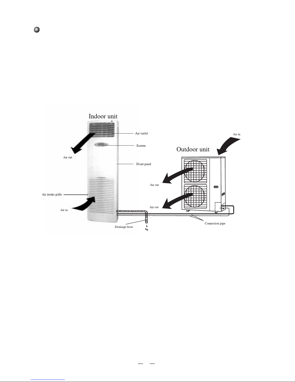
STRUCTURE
3
4
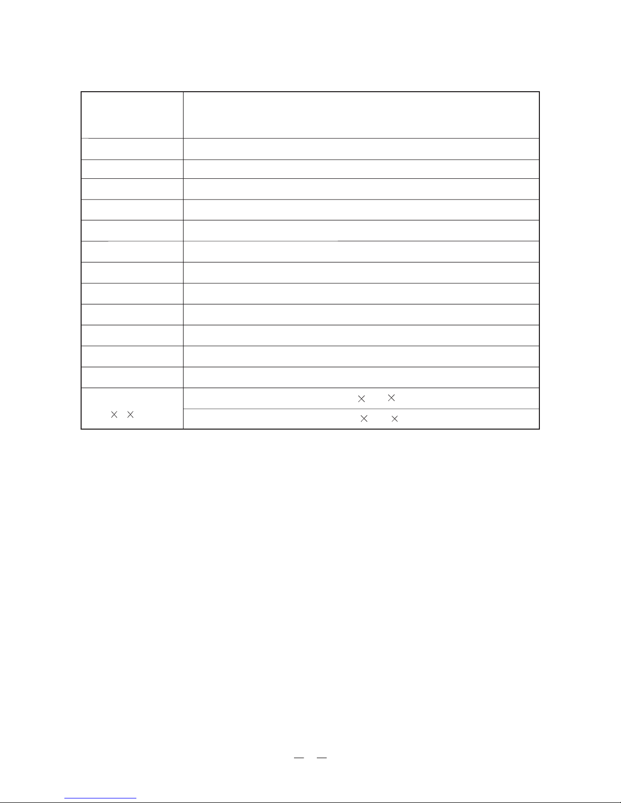
MODELS & SPECIFICATIONS
All above should be changed without notice, there are latest and accurate specifications on the nameplate of your
air conditioner.
Cooling capacity (W)
Heating capacity (W)
Power supply
Input power (W)
Air flow volume (m
3
/h)
Refrigerant
Noise (in/out) dB(A)
Climate
Water resistance level
Isolation
Weight (in/out) (kg)
Dimension(in/out)
(W H D) (mm)
Model
Functions
RFI-66B /RFO-66B
6400/6200(9700)
16000
18000(21500)
380-415V 3N~ 50Hz
2000
58/63
T1
IP24
I
60/115
Indoor:540
1750 380
Outdoor:950
1250
412
Cool Heat
R410A 5.0
5
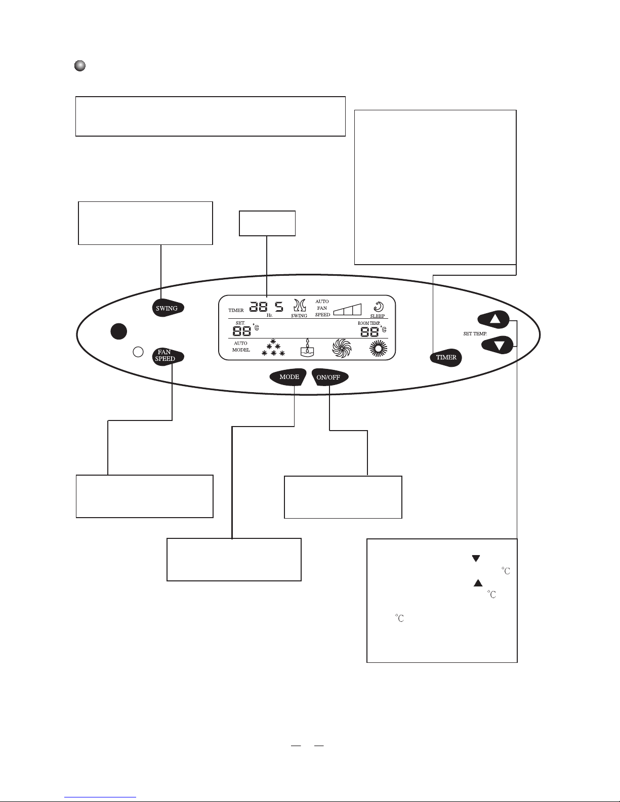
CONTROL PANEL
Floor standing type air conditioner with LCD control panel
SWING key
Choose between SWING and stop
modes.
LCD screen
FAN SPEED key
Choose between AUTO/LO/MED/
HI speeds.
MODE key
Choose between AUTO/COOL/
DRY/FAN/HEAT modes.
ON/OFF key
Press once to start and press
once more to stop the unit.
SET TEMP. key
Every time when pressing
,the set
room temperature is lowered by 1
,
every time when pressing
, the set
room temperature is raised by1
.The
room temperature can be set between
16-30
. In normal operation, pressing
the two keys at the same time will shield
the screen, and pressing the two keys
once more will release the shield.
When the air conditioner is in OFF mode,
the key is used to set the time when the
unit is to be started. and every time when
pressing, the time interval being set will
be 0.5 hour more or less, ranging from
0.5-24 hour (s). when the set time arrives,
the unit will run in the set modes. When
the air conditioner is in ON mode,the key
is used to set the time when the unit is to
be stopped, and the time interval to be set
scrolls between 0.5-24 hour (s). When the
set time arrives,the unit will stop running.
6
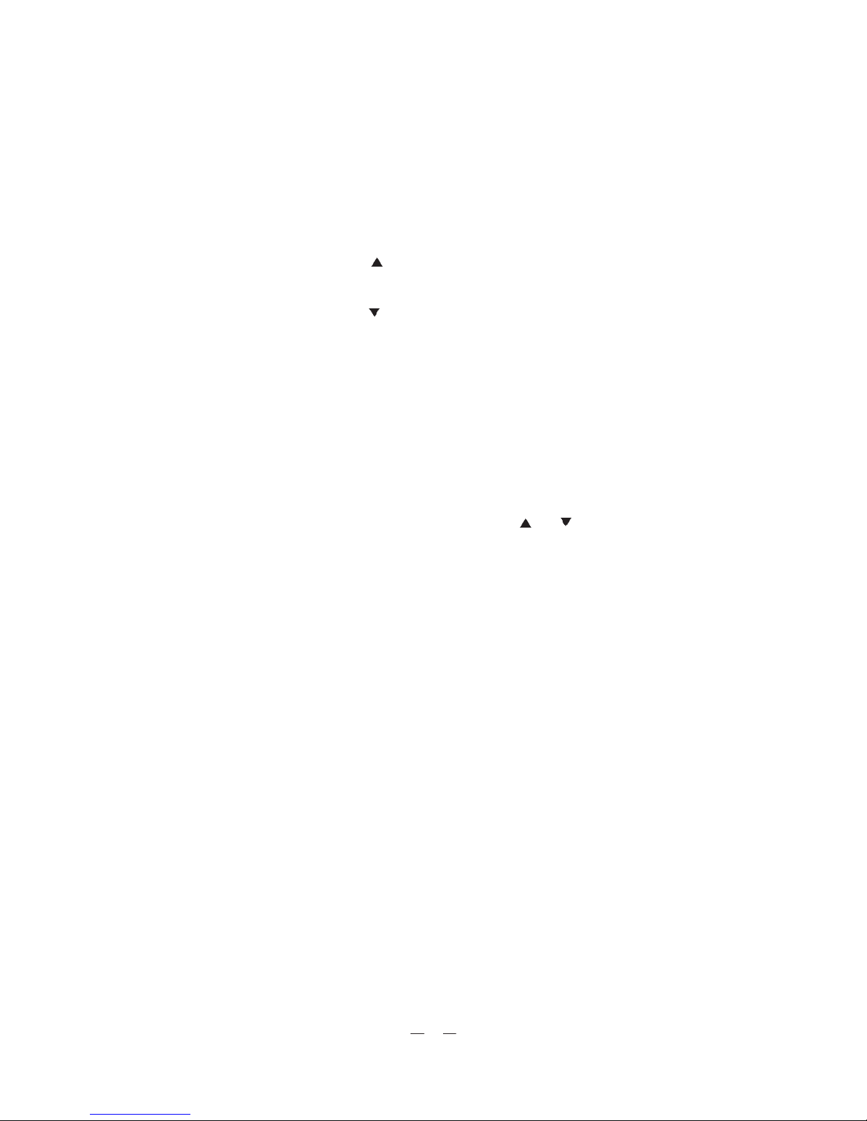
SPECIAL FUNCTIONS:
Test function:
Every time when the unit is plugged on and there is not any key signal is accepted:
(1) Press SET TEMP. key
to enter forced cooling mode, the compressor starts and the unit is in
auto swing mode, indoor and outdoor fans run at high speed. LCD displays all symbols. Five
minutes later, the unit stops and enter normal waiting mode.
(2) Press SET TEMP. key
to enter forced heating mode, the compressor and supplementary electric
heater starts and the unit is in auto swing mode, indoor and outdoor fans run at high speed. LCD
displays all symbols. Five minutes later, the unit stops and enter normal waiting mode.
Compressor running protection function:
In all modes, compressor needs 3 minutes to restart once it has been stopped; if there is no changes in
mode, the compressor will keep running for 6 minutes before it can be stopped. Between changes
of modes, compressor will stop for 3 minutes.,
Shielded screen function:
In normal running, pressing the two SET TEMP. keys and at the same time will shield all
functions of keys on the screen, pressing the two key simultaneously once more will release the
shield.
- 7 -
- 8 -
- 9 -
- 10 -
- 11 -
- 12 -

- 13 -

- 14 -
- 15 -
16
2. Breeze guided up and down
Readjust breezing angles of air louvers with hands. Hold
two ends of the louvers with both hands when doing
the readjustment. When cooling and drying, set to
breeze straightly or upwards; when heating, set to breeze
downwards.
When cooling and drying, set to breeze straightly or upwards
1. Breeze guided left and right
* Press SWING key on control panel
to choose SWING and END SWING, then the swing
louvers will swing left and right or stop swinging
and breeze from a fixed direction.
*
Every time when pressing SWING, “SWING” will appear
on LCD,if indoor fan is already working, then swing motor
will start and breeze left and right ;press the key once more,
“SWING” disappears from LCD, swing motor stops, the
louvers stop swinging and breeze from a fixed direction.
Breeze Guided
Swing louvers
(guide wind breeze
horizontally).
Breeze
straightly
Breeze
upwards
When heating, set to breeze downwards.
Breeze
downwards.
MAINTENANCE
17
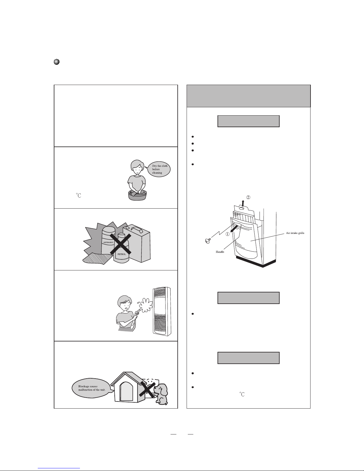
1.Cut power off before cleaning
Cleaning unit Cleaning the air filter
Air filter should be cleaned every two weeks
Removing air filter
Make sure that the A/C has been turned off.
Remove screw from handle of air intake grille.
Pull out air intake grille by the handle towards
direction.
Air filter is attached to the air intake grille. Pull out
the filter towards direction.
Cleaning
Clean by patting the filter softly or use an electric
vacuum. If too much accumulated on the filter, use
water with containing some neutral detergent to
clean, then wash with tap water. Dry after cleaning
and put it back into place.
Note
Do not dry the filter by exposing it under direct sun-
shine or near a heating oven, or it may get deformed.
The filter may get deformed when it is cleaned with
hot water (above 50
).
2.Use soft cloth
when cleaning
cabinet.
If the cabinet is very dirty,
dip cloth into warm water
below 40
, dry the cloth and
then rub off the dirt.
3. Don’t use acid and alkaline solution to clean.
* Make sure there is nothing
blocking the air in and out of the
outdoor unit.
4. Don’t spray water on indoor unit
Care and maintenance
Plug out only after air conditioner stops at all.
18
If your air conditioner is not working properly, please check the following before asking for help. After checking the
following point and the A/C is still not working normally, please contact the nearest service center to examine it.
The A/C does not start
The A/C stops soon after
started, screen displays
“E1”
The A/C stops soon after
started, screen displays
“E2”
TEMP. indicates 0
and
the COOL mode is not
working
Poor cooling performance
Poor heating performance
1. No power
2. Electricity leakage switch shut down
3. Voltage too low
4. Operation key turned off
5. Controlling circuit troubles
1. Blocking in front of condenser
2. Controlling circuit troubles
3. Cooling operation when outdoor temp. is
above 43
4. The tube pressure is too high.
1. Indoor fan motor doesn’t work or air outlet
get blocked
2. Indoor temp. is below 18
3. Wire of tube temp. sensor broken
4. Tube temp. sensor not in place
5. Controlling circuit troubles
6. Electricity leakage of capacitor
1. Wire of room temp. sensor broken
2. room temp. sensor not in place
3. Electricity leakage of capacitor
1. Air filter is too dirty or get clogged
2. There are too many people or heating sources
in the room
3. Door or window opened
4. Air in/out is blocked
5. Set temp. too high
6. Leakage of refrigerant
7. Poor performance of room temp. sensor
1. Air filter is too dirty or get clogged
2. Door or window opened
3. Set temp. too low
4. Leakage of refrigerant
5. Outdoor temp. below-5
6. Controlling circuit troubles
1. Connect to power supply
2. Contact service center
3. Contact electrician or dealer
4. Press Operation key again
5. Contact service center
1. Clear blocking
2. Contact service center
3. Put outdoor unit at shady place
4. Contact service center
1. Contact service center
2. Check if there is the need to turn on the A/C
3. Contact service center
4. Fit tube temp. sensor into place
5. Contact service center
6. Contact service center
1. Connect wire of room temp. sensor
2. Fit room temp. sensor into place
3. Contact service center
1. Clean air filter
2. Clear heating sources if possible
3. Close door and window
4. Clear blocking to insure free air flow
5. Set lower temp.
6. Contact service center
7. Replace room temp. sensor
1. Clean air filter
2. Close door and window
3. Set higher temp
4. Contact service center
5. Heating performance is affected
6. Contact service center
Troubles Possible Causes Solution
Trouble shooting
The A/C stops soon after
started, screen displays
“E3”.
The A/C stops soon after
started, screen displays
“E4”.
1.Leakage of refrigerant
2.Controlling circuit troubles
1.Contact service center
2.Contact service center
1.Leakage of refrigerant
2.Controlling circuit troubles
3.wire of sensor broken
4.Voltage is too low
1.Contact service center
2.Contact service center
3.Contact service center
4.Contact service center
19
INSTALLATION
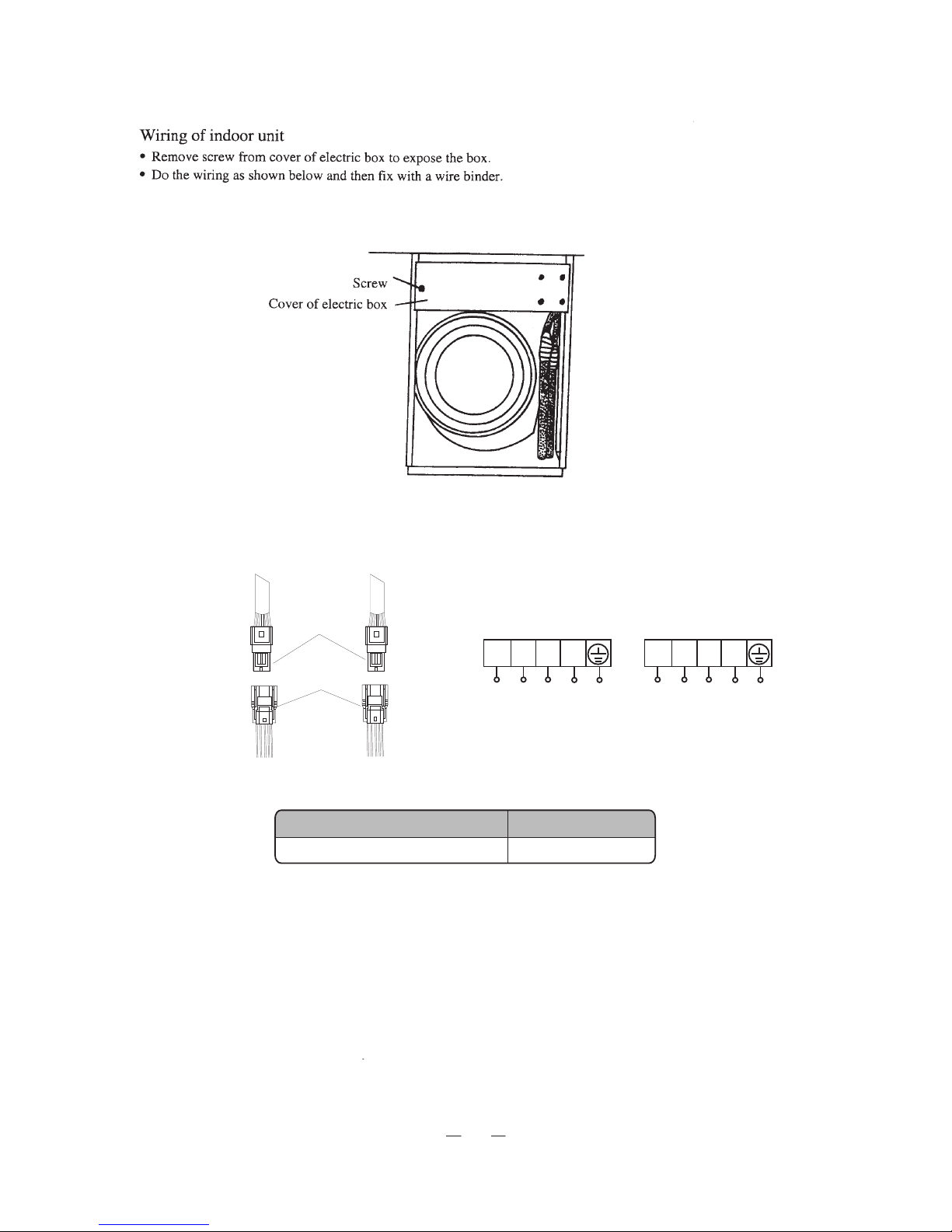
Electric wiring
Please read this manual carefully before installation.
Please strictly follow the instructions of this manual when installing indoor unit and its piping.
First install wire of outdoor unit and then wire of indoor unit. After finishing wiring and piping, connect the unit to the
power supply.
Design of the unit is subject to change without prior notice.
Wiring Example
Model
Power supply
Input capacity Air switch
Lines
Cross section area of
power cord (mm
2
)
Minimum cross section area
of indoor/outdoor power
connecting cable (mm
2
)
Note:
1. Please pay attention to surrounding conditions (eg. ambient temperature, direct sun shine, rain drops etc.).
2. When the voltage declines, please use thicker power conducting wires.
3. Earth wire must be connected to both of indoor and outdoor units.
4. Data listed in this table is for reference only, and please do the wiring according to relevant government rules
a
nd regulations.
25A
2.5/1.5
/
380
RFI-66B/RFO66B
-415V 3N~50Hz
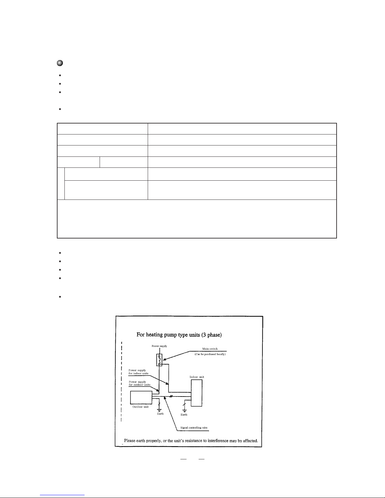
Special circuit must be used for power supply.
The circuit must be installed by special serviceman.
Please do the wiring according to the following wiring diagram. The screws must be tightly fastened.
Connecting wire and power conducting wire between the indoor/outdoor units must be properly arranged so that they
do not touch each other.
Please connect the power phase correctly. If the connection is wrong, the unit will stop automatically in such case,
exchange the connection of two of the three phasewires and the air conditioner can work normally again.
20
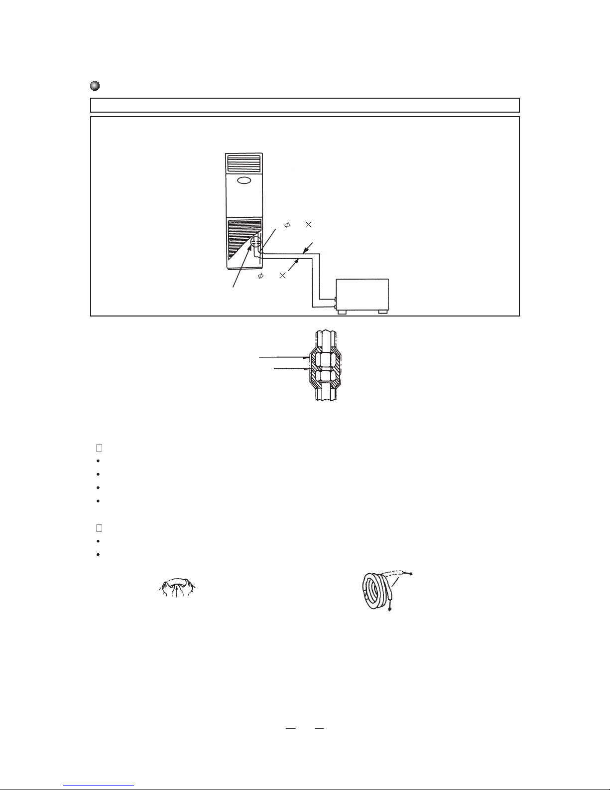
Notes for piping
Pipes for refrigerant and drainage should be insulated to avoid frosting and dripping.
Both of the indoor and outdoor units adopt flare-end connection.
Refrigerant pipe as shown below is used to connect indoor and outdoor units.
Note: Don’t bend the bendable pipe back and forth more than 3 times.
Note: Insulate all exposed parts of the flare-end connection joint and the refrigerant pipe.
2. When using copper pipe bought locally
Check valve of the outdoor unit should be shut (like position unworking). After the refrigerant pipe has been connected to both indoor and outdoor units, exhaust from service mouth on low-pressure check valve of the outdoor
unit. After exhausting, put back nut of the service mouth and fasten.
3. After finishing step 1 and 2, check valve of outdoor unit should be fully open so that there is not blockage between
the indoor and outdoor refrigerant pipe.
Note: before fastening nut of the flare-end pipe, please apply some refrigerant oil to the end of the pipe and the joint.
1. Connecting the pipe
Check valve of the outdoor unit should be shut (like position unworking). Every time when connecting, remove
bonnet from the check valve and connect to flare-end pipe immediately (within five minutes), otherwise dust, moisture and other small things may go into the pipe and cause troubles.
About the bendable pipe
The part with bendable pipe should be used on the indoor side.
The bending angle should not be more than 90.
It’s better for the bend to be in the middle of the pipe, and the radius of the bend is the bigger the better.
Don’t bend the bendable pipe more than three times.
When bending the pipe
Cut some part of the insulation pipe at the place of the bend (and wrap with polythene tape after bending)
Make radius of the bend as big as possible so that the pipe will not get flat or broken.
Indoor unit
Bendable pipe
19 1
Flare-end connection
12 1
Outdoor unit
Polythene tape
Insulation cover
Loosen the roll of pipe
Straighten end of pipe
Bend the pipe with thumb
Minimum radius: 100mm
21
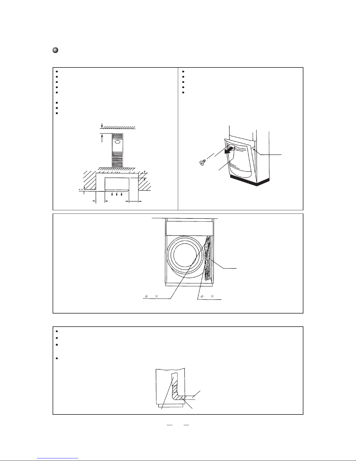
Installation of indoor unit
1. Choose a place 2. Install pipes
Where it’s least likely to be affected by outdoor air.
Where free flow of air in and out of the unit will not be blocked.
Where the refrigerant pipe can be easily lead outdoors.
Where conditioned air can reach every corner of the room.
Where there is not too much moisture and can not be easily splashed
with oil.
Where there inflammable gas is not likely to leak or stay.
Choose a solid and even ground.
Leave enough space for installation and maintenance.
Remove air intake grille.
Before wiring and piping, please remove air intake grille.
Remove screw from the grille.
Open the grille by pulling it out by the handle.
Remove chain and take off the whole grille.
3. Install drainage pipe
Make sure drainage pipe is leading to the outdoor side (discharge side.)
Joint drainage pipe with blow moulding drainage pipe and fix with tape from the accessories.
If the drainage pipe needs to be led indoors, please wrap it with insulation material (at least 9mm thick), and then wrap with tape to prevent
air from going into the pipe and cause congealing.
After connecting, check if water can be discharged properly and if there is any leaking.
>30cm
>4cm
>5cm
>10cm
(Pipe side:30cm min.)
Front
>200cm
>10cm
(Pipe side:
30cm min.)
Chain
Screw
Handle
Drainage pipe
19 1
Refrigerant pipe
12 1
Flare-end connection Flare-end connection
Drainage pipe of indoor unit
Blow moulding drainage pipe
Drainage pipe
Wrapping tape
22
Signal wires
(2) For heating pump type units (5 phawe)
Terminal board of indoor units
Power supply
Power supply
Terminal board of outdoor units
Wire interface
L1 L2
L3 N
L1 L2
L3 N
Air switch capacity
Models
RFI-66B/RFO-66B
25A
23
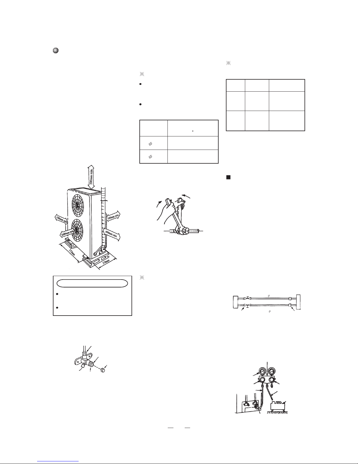
Installation of outdoor unit
1. Choose a place
Note:
The outdoor unit must be installed on
solid foundation to minimize noise and
vibration.
The air outlet must not be blocked.
In coastal area, places of high altitude
or strong wind, please install the unit
against the wall or use wind block.
Install the unit with good ventilation
instead of a sealed space.
Installation hole size: 572x327mm.
2. Connecting of refrigerant pipe
Tightening joint
Match pipes
Screw nut with hand and then tighten
with wrench (see figure below).
Be careful not to twist too tightly or
the nut may get damaged.
Open valve stem until it touches limit
block and don’t open further.
Tighten bonnet with wrench.
When operating the check valve, please note:
Diameter
(mm)
Twisting moment
(N m)
12 45-50
19 70-75
Length of
pipe
Exhausting
Value of refrigerant
charge
5m
5-15m
Use
refrigerant
of outdoor
unit
As value on the
nameplate
Use
vacuum
pump
Nameplate value
+30g/m (charge 30g
more for every meter
added to the pipe
Manifold
Valve
Multimeter
-76cmHg
Lo Handle
Charging hose
Manometer
Hi handle
Charging hose
Vacuum pump
Low pressure valve
Joint nut
Limit block
Bonnet
one-way valve
Valve stem
Exhausting (with
hexagon wrench)
*1.See section about vacuum pump or
refrigerant tank.
*2.Charge refrigerant according to
value listed above. If the unit is to be
moved to other place, please evacuate
with vacuum pump or refrigerant tank.
When using refrigerant of outdoor
unit:
*1.Tighten nuts A,B,C,D substantially.
*2.Remove cover from check valve A.
*3.Twist open core of liquid valve B
with hexagon wrench, and at the same
time hold screw driver against core of
gas valve A to let gas out.
After 15 seconds of exhausting and
refrigerant appears, close one way
valve and tighten bonnet.
*4.Fully open cores of both liquid
valve and gas valve, tighten bonnet,
then check with soap water or leakage
detector to see if there is any leaking
in the joints of piping between indoor
and outdoor units.
*6.Fully open high/low pressure
valves.
*7.Remove charging hose from charging end of low pressure valve.
*8.Tighten bonnet
of low pressure
valve.
When using the vacuum pump
*1.Connect charging hose of manifold
valve to charging end of low pressure
valve (both high/low pressure valves
must be tightly shut).
*2. Connect joint of charging hose to
vacuum pump.
*3.Fully open handle of Lo manifold
valve.
*4.Ope n the vacuum p ump to
evacuate. At the beginning, slightly
loosen joint nut of low pressure valve
to check if there is air coming inside.
(valve of vacuum pump changes from
negative to 0) Then tighten this nut.
*5.After finishing evacuation, shut Lo
handle of manifold valve to stop the
vacuum pump. Keep evacuating for
more than 15 minutes and make sure
the rea
ding of multimeter is -1.0x10
5
pa
(-76cmHg).
Outdoor unit
Gas side
Indoor unit
Check valve
Pipe joint
A
B
C
D
12mm
19mm

24
3.Wiring
Remove front plate.
Open outdoor wiring hole and fit on ring for wiring.
Lead connecting wire from terminal board of outdoor unit, thread it through outdoor wiring
hole and indoor wiring hole, then connect to indoor terminal board.
Connect wires as shown bellow and then fix with wire clamp.
Trial running
After finishing leakage
check, start trial running.
Cooling
Set cooling mode.
See owner’s manual for details.
3-minute protection
If the unit is stopped, it needs 3 minutes to
be restarted.
3~220V 60Hz
Signal wires
Outdoor signal wires

25
Install slant protection cable
Note:
In order to avoid any accidental slant for outdoor unit,please
install slant protection cable.
Installation steps:
1.Take out the screw from the indoor unit top cover (Pic 1)
2.Take out the slant protection cable, put it in the slant protection
hole, fasten it with screws. (Pic 2)
2.Fix another end of cable to the wall by using screw (ST4.2X38)
Take out the screw
protection hole
Fix this end to the wall
Put this end in the
hole,fasten it
Wall
Indoor unit
Pic 1
Pic 2
Abov e scheme for installation referenc e only, indo or uni t may be different .

Activate your warranty.....
in
5
simple
steps!
For the electronic
warranty submission
please use the following link
Scan here for the
warranty form
http://www.inventoraiconditioner.com
/warranty-inventor
Select the product type
(airconditioner or appliance) for
which the warranty will be activated
Choose the warranty that
corresponds to your product
purchase
Fill in the required information
(owner, retailer and appliance)
and press send
You will receive a confirmation
e-mail for the activation of
your warranty
Connect to the following link
http://www.inventorairconditioner.com/warranty-inventor

1
ΠΕΡΙΕΧΟΜΕΝΑ
Σημειώσεις πρίν τη χρήση
Δομή
Συντήρηση
Δομή
Μοντέλα & προδιαγραφές
Πάνελ ελέγχου
Κατεύθυνση αέρα
Φροντίδα & συντήρηση
Έλεγχος σφαλμάτων
2
3
4
5
16
17
18
19
20
21
23
24
25
Ηλεκτρολογική καλωδίωση
Σημειώσεις για την σωλήνωση
Εγκατάσταση της εσωτερικής μονάδας
Εγκατάσταση της εξωτερικής μονάδας
Εγκατάσταση σύρμματος προστασίας κλίσης
Δοκιμαστική λειτουργία
Εγκατάσταση
Τηλεχειριστήριο
7

2
ΣΗΜΕΙΩΣΕΙΣ ΠΡΙΝ ΤΗ ΧΡΗΣΗ
Απαιτήσεις τροφοδοσίας
Εύρος θερμοκρασίας για την σωστή λειτουργία
1. Το φορτίο του παρεχόμενου ρεύματος πρέπει να είναι τουλάχιστον 10kw, και η διατομή των καλωδίων πρέπει
να είναι τουλάχιστον 2.5mm
2.
Συμβουλευτείτε τον προμηθευτή σας για λεπτομέρειες.
2. Το κλιματιστικό πρέπει να γειωθεί με ασφάλεια. Το καλώδιο της γείωσης πρέπει να συνδεθεί στην ειδική συσκευή
του κτιρίου και όχι σε αγωγό ν
ερού ή αερίου.
3.
Η καλωδίωση πρέπει να γίνει από εξειδικευμένο τεχνικό και σύμφωνα με τους αντίστοιχους νόμους και κανονισμούς.
4. Σε ένα σταθερό κύκλωμα, πρέπει να υπάρχει ασφάλεια διαφυγής με επαρκές φορτίο και διακόπτης αέρα με αρκετό χώρο.
5.Αποσυνδέστε το από την παροχή ρεύματος όταν δεν το χρησιμοποιείτε.
Απαιτήσεις ασφαλείας
Διαβάστε αυτό το εγχειρίδιο προσεκτικά πρίν τ
η χρήση της μονάδας και επικοινωνήστε με τον προμηθευτή σας ή με το
τμήμα εξυπηρέτησης πελατών εάν έχετε απορίες ή κάποιο πρόβλημα.
Το κλιματιστικό είναι κατάλληλο προς χρήση μόνο για τον σκοπό που περιγράφεται σε αυτό το εγχειρίδιο.
ΠΟΤΕ μην χρησιμοποιείτε ή αποθηκεύετε βενζίνη ή άλλα εύφλεκ
τα αέρια ή υγρά κοντά στο κλιματιστικό, είναι
πάρα πολύ επικίνδυνο!
Το κλιματιστικ
ό δεν έιναι εξοπλισμένο με συσκευή για να φέρνει φρέσκο αέρα από το εξωτερικό χώρο, επομένως
όταν χρησιμοποιείτε θερμάστρα αερίου στον χώρο, ανοίγετε τα παράθυρα συχνά ώστε να αερίζεται ο χώρος, καθώς
τέτοιου είδους θερμάστρες καταναλώνουν το οξυγόνο του χώρου το οποίο μπορεί να προκαλέσει δυσφορία στους
παρεβρισκόμενους λόγω έλλειψης οξυγόνου.
• Μην εκκινείτε ή σταματάτε την μονάδα ανοιγοκλείνοντας τον διακόπτη παροχής, πιέστε το
πλήκτρο ON/OFF.
• Μην εισάγετε τίποτα στους αεραγωγούς της μονάδας.
•
Μην αφήνετε τα μικρά παιδιά να χειρίζονται τη μονάδα.
• Εάν στον χώρο υπάρχουν μικρά παιδία ή ασθενείς ρυθμίστε τη θερμοκρασία κατάλληλα.
Συνθήκες
λειτουργίας
Θέρμανση
Θερμοκρασία Εσωτερική Θερμοκρασία
27°C
(ξηρό θερμόμετρο) 24°C (ξηρό θερμόμετρο) / 18°C (υγρό θερμόμετρο)
-5°C (ξηρό περιβάλλον) / -6°C (υγρό περιβάλλον)
20°C (ξηρό θερμόμετρο)
Εξωτερική Θερμοκρασία
Μ
έγιστο
Ελάχιστο
ΠΡΟΕΙΔΟΠΟΙΗΣΗ
ΠΡΟΣΟΧΗ

3
ΔΟΜΗ
Έξοδος αέρα
Εσωτερική μονάδα
Εξωτερική μονάδα
Αγωγός
αποστράγγισης
Σωλήνα σύνδεσης
Έξοδος αέρα
Έξοδος αέρα
Εξαγωγή αέρα
Οθόνη
Εμπρόσθιο πάνελ
Είσοδος αέρα
Είσοδος αέρα
Γρίλια εισαγωγής αέρα

4
Μοντέλο & Προδιαγραφές
Ό
λα τα παραπάνω μπορεί να αλλάξουν χωρίς προειδοποίηση, τα αναεωμένα στοιχεία βρίσκοντα στο ταμπελάκι
που βρίσκεται πάνω στην μονάδα.
Λειτουργίες
Απόδοση ψύξης(W)
Απόδοση θέρμανσης(W)
Παροχή ρεύματος
Ισχύς εισόδου(W)
Όγκος ροής αέρα(m3/h)
Ψυκτικό μέσο
Θόρυβος (εσ./εξ.)dB(A)
Κλιματική κλάση
Επίπεδο αντίστασης νερού
Μόνωση
Βάρος(εσ./εξ.)(kg)
Διαστάσεις(εσ./εξ.)
(ΠxΥxΒ) (mm)
Μοντέλο
RFI-66B /RFO-66B
6400/6200(9700)
16000
18000(21500)
380-415 V 3N ~ 50H z
2000
58/63
T1
IP24
I
60/115
Εσωτερική: 540x1750x380
Εσωτερική: 950x1250x412
Ψύξη/Θέρμανση
R410A 5.0

5
Πλήκτρο SWING
Επιλέξτε την κίνηση των
περσίδων ή την στάση τους.
Πλήκτρο FAN SPEED
Επιλέξτε την ταχύτητα του ανεμιστήρα
από αυτ/τη-χαμηλή-μεσαία-υψηλή
Πλήκτρο MODE
Επιλέξτε τo πρόγραμμα λειτουργίας
από Αυτόματη/Ψύξη/
Αφύγρανση/Ανεμιστήρα/Θέρμανση
Πλήκτρο ON/OFF
Πιέστε το μια φορά για να
ενεργοποιήσετε τη μονάδα και
ξανά πιέστε το για να την
απενεργοποιήσετε
Πλήκτρο SET TEMP.
Κάθε φορά που πιέζετε το ,η ρυθμισμένη
θερμοκρασία του χώρου κατεβαίνει κατά 1°C,
κάθε φορά που πιέζετε το ,η ρυθμισμένη
θερμοκρασία του χώρου ανεβαίνει κατά 1°C.
Η ρυθμισμένη θερμοκρασία του χώρου μπορεί
να οριστεί σε εύρος 16~30°C. Υπό κανονική
λειτουργία, πιέζοντας τα δυο πλήκτρα ταυτόχρονα, θα κλειδώσουν τα πλήκτρα της οθόνης,
πιέζοντας τα ξανά μαζί τα πλήκτρα θα ξεκλειδώσουν
Όταν το κλιματιστικό είναι απενεργοποιημένο, το
πλήκτρο χρησιμοποιείται για να οριστεί η ώρα
ενεγοποίησης του κλιματιστικού. Με κάθε πάτημα,
η ώρα αλλάζει κατά 30 λεπτά με εύρος από 30
λεπτά έως 24 ώρες. Όταν φτάσει η ρυθμισμένη
ώρα, η μονάδα θα λειτουργήσει υπό το ορισμένο
πρόγραμμα. Όταν το κλιματιστικό είναι ενεργοποιημένο, το πλήκτρο χρησιμοποιείται για να οριστεί
η ώρα απενεργοποίησης. Με κάθε πάτημα, η ώρα
αλλάζει κατά 30 λεπτά με εύρος από 30 λεπτά έως
24 ώρες. Όταν φτάσει η ρυθμισμένη ώρα, η μονάδα
θα απενεργοποιηθεί.
Πάνελ Ελέγχου
Κλιματιστική μονάδα ντουλάπα εμφανούς τύπου με οθόνη LCD
Οθόνη LCD

6
Ειδικές Λειτουργίες
Λειτουργία προστασίας συμπιεστή
Σε όλες τις λειτουργίες, ο συμπιεστής χρειάζεται 3 λεπτά για να επανεκκινηθεί εάν έχει σταματήσει.
Εάν δεν υπάρχουν αλλαγές στο πρόγραμμα λειτουργίας, ο συμπιεστής θα λειτουργεί για 6 λεπτά
προτού μπορέσει να σταματήσει. Ενδιάμεσα από τις αλλαγές προγράμματος ο συμπιεστής θα
σταματά για 3 λεπτά.
Λειτουργία κλειδώματος των πλήκτρων
Υπό κανονική λειτουργία, πιέζοντας ταυτόχρονα τα πλήκτρα και , θα κλειδώσουν τα πλήκτρα
του πάνελ. Πείζοντάς τα ξανά μαζί τα πλήκτρα θα ξεκλειδώσουν.
Δοκιμαστική Λειτουργία
Κάθε φορά που συνδέεται η μονάδα στο ρεύμα και δεν δέχεται εντολές από τα πλήκτρα:
(1) Πιέστε το πλήκτρο για να μπεί η μονάδα σε αναγκαστική ψύξη, ο συμπιεστής ξεκινά
και οι περσίδες κινούνται αυτόματα, η ταχύτητα του ανεμιστήρα της εσωτερικής και της
εξωτερικής μοναδας είναι υψηλή. Στην οθόνη LCD εμφανίζονται όλα τα σύμβολα.
Μετά από 5 λεπτά, η μονάδα θα σταματήσει και θα είναι σε αναμονή.
(2) Πιέστε το πλήκτρο για να μπεί η μονάδα σε αναγκαστική θέρμανση, ο συμπιεστής
και η βοηθητική ηλεκτρική αντίσταση ενεργοποιούνται και οι περσίδες κινούνται αυτόματα,
η ταχύτητα του ανεμιστήρα της εσωτερικής και της εξωτερικής μονάδας είναι υψηλή. Στην
οθόνη LCD εμφανίζονται όλα τα σύμβολα. Μετά από 5 λεπτά, η μονάδα θα σταματήσει
και θα είναι σε αναμονή.

- 7 -
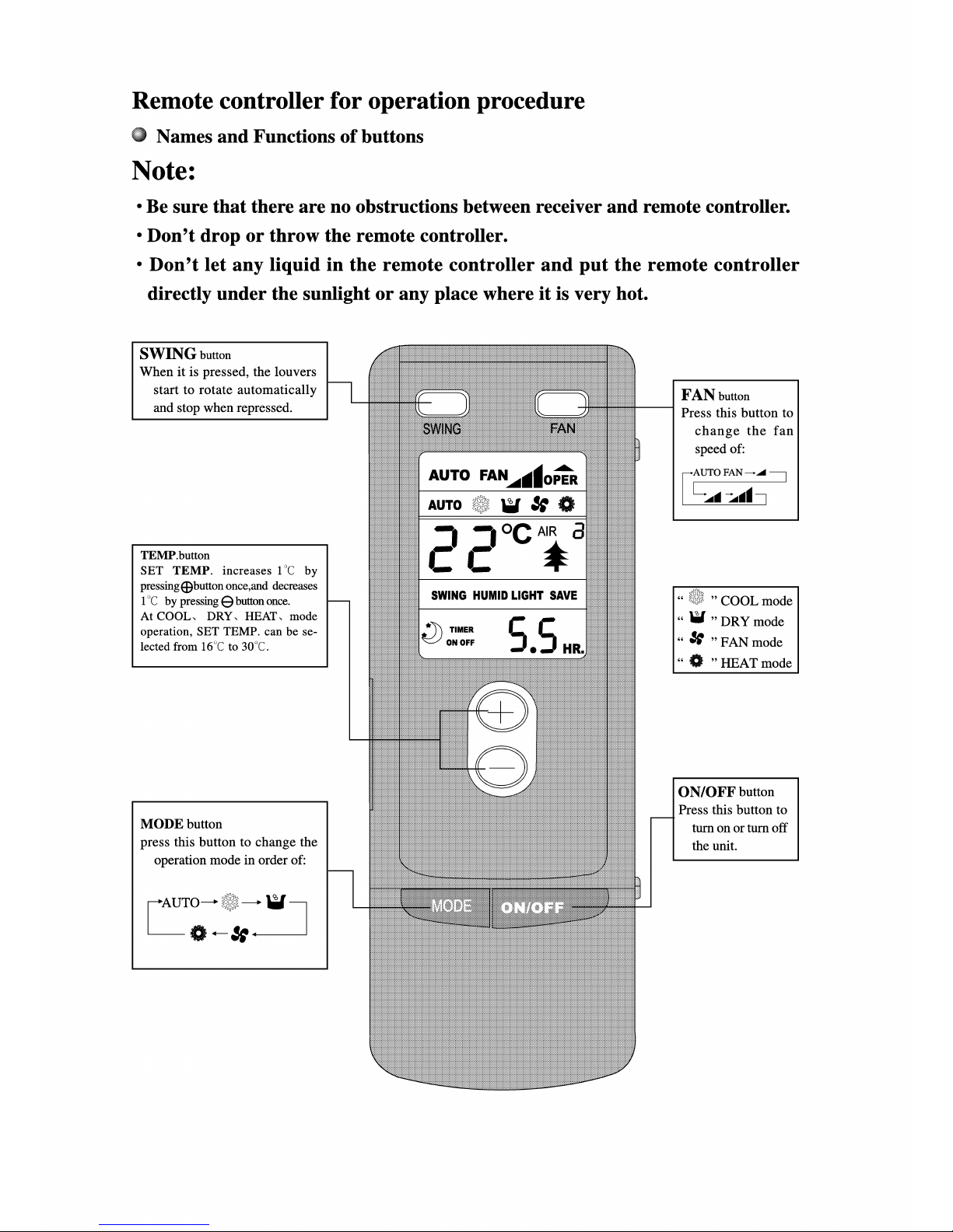
Πλήκτρο MODE
Πιέστε αυτό το πλήκτρο για
να αλλάξετε το πρόγραμμα
λειτουργίας με την ακόλουθη
σειρά:
Πλήκτρο TEMP.
Αυξάνει την θερμοκρασία κατά
1°C πιέζοντας το
+ , και μειώνει
τη θερμοκρασία κατά 1°C
πιέζοντας το
- .
Κατά την Ψύξη, Αφύγρανση,
Θέρμανση, η ορισμένη
θερμοκρασία μπορεί να επιλεγεί
από 16°C~30°C.
Πλήκτρο SWING
Πιέζοντας αυτό το πλήκτρο
ξεκινά η αυτόματη κίνηση των
περσίδων. Πιέζοντάς το ξανά
η κίνηση σταματά.
Τηλεχειριστήριο
Σημείωση:
• Βεβαιωθείτε οτι δεν υπάρχουν εμπόδια μεταξύ του δέκτη και του τηλεχειριστηρίου.
• Μην πετάτε ή χτυπάτε το τηλεχειριστήριο.
• Μην αφήσετε να πέσουν υγρά στο τηλεχειριστήριο και μην το αφήνετε σε σημείο
με απευθείας έκθεση στον ήλιο ή σε πολύ θερμό σημείο.
Ονομασία και λειτουργίες των πλήκτρων.
Πλήκτρο FAN
Πιέστε αυτό το πλήκτρο
για να επιλέξετε την
ταχύτητα του ανεμιστήρα:
Πλήκτρο ON/OFF
Πιέστε αυτό το πλήκτρο για να
ενεργοποιήσετε/απενεργοποιήσετε
τη μονάδα.
Πρόγραμμα Ψύξης
Προγραμμά Αφύγρανσης
Πρόγραμμα Ανεμιστήρα
Πρόγραμμα Θέρμανσης

- 8 -
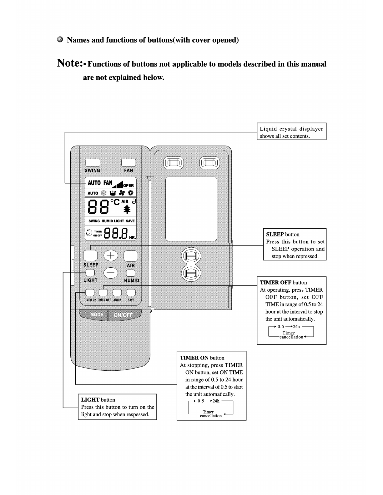
Πλήκτρο LIGHT
Πιέστε αυτό το πλήκτρο
για να ανάψετε το φώς
και ξαναπατήστε το για
να σβήσει.
Πλήκτρο TIMER OFF
Πιέστε αυτό το πλήκτρο
για να ορίσετε την ώρα
απενεργοποίησης σε εύρος
από 30 λεπτά έως 24 ώρες.
Πλήκτρο SLEEP
Πιέστε αυτό το πλήκτρο
για να ενεργοποιήσετε
τη λειτουργία SLEEP.
Ξαναπατήστε το για να την
απενεροποιήσετε.
Οθόνη υγρών κρυστάλλων
Αναγράφει όλες τις ρυθμίσεις
Ονομασίες και λειτουργίες των πλήκτρων (με ανοιχτό το κάλυμμα)
ΣΗΜΕΙΩΣΗ: Η λειτουργία των πλήκτρων δεν εφαρμόζεται σε μοντέλα τα οποία δεν
περιέχονται σε αυτό το εγχειρίδιο.
Ακύρωση
χρονοδιακόπτη
Πλήκτρο TIMER ON
Πιέστε αυτό το πλήκτρο
για να ορίσετε την ώρα
ενεργοποίησης σε εύρος
από 30 λεπτά έως 24 ώρες.
Ακύρωση
χρονοδιακόπτη

- 9 -
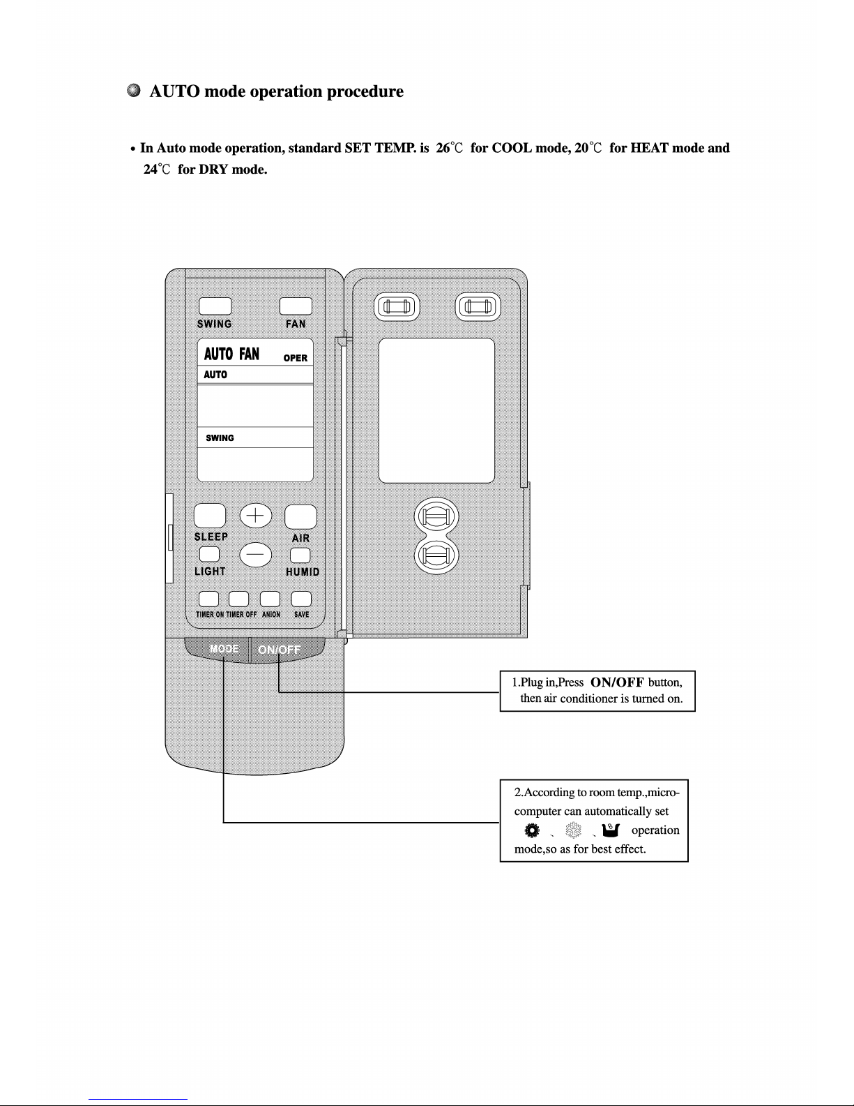
Σύμφωνα με τις συνθήκες του χώρου,
ο επεξεργαστής μπορεί να ορίσει
αυτόματα
για το καλύτερο αποτέλεσμα.
Πιέστε το πλήκτρο ON/OFF
και το κλιματιστικό θα
ενεργοποιηθεί.
ΑΥΤΟΜΑΤΗ ΛΕΙΤΟΥΡΓΙΑ
• Στην αυτόματη λειτουργία, η ρυθμισμένη θερμοκρασία είναι 26°C για την ψύξη, 20°C για τη
θέρμανση και 24°C για την αφύγρανση.

- 10 -
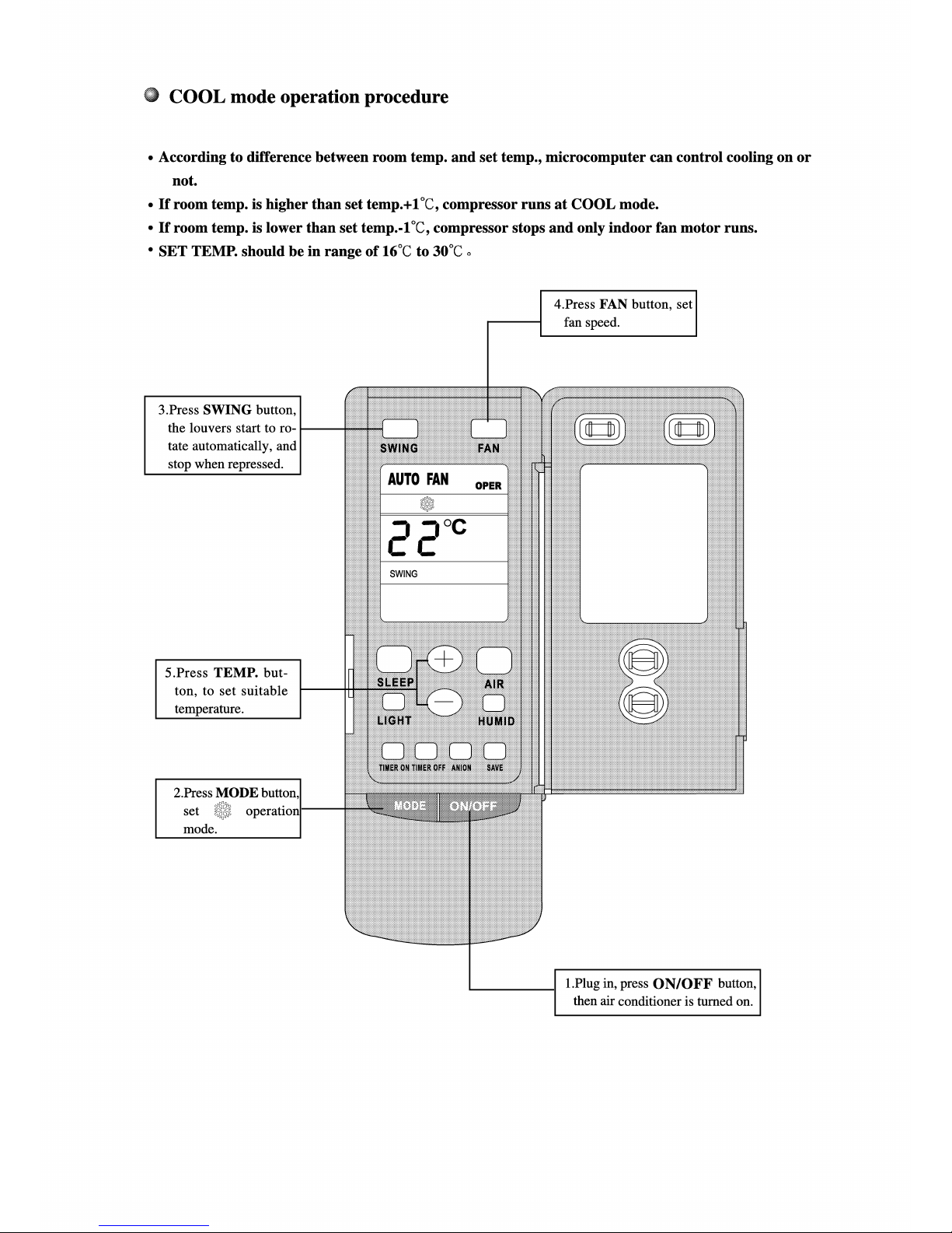
1.Πιέστε το πλήκτρο ON/OFF
και το κλιματιστικό θα ενεργοποιηθεί
2. Πιέστε το πλήκτρο MODE, και
ρυθμίστε τη λειτουργία
5. Πιέστε το πλήκτρο TEMP και
ορίστε την επιθυμητή θερμοκρασία
3. Πιέστε το πλήκτρο SWING για
να ξεκινήσει η κίνηση των περσίδων.
Ξαναπατήστε το για να σταματήσει η
κίνηση
4. Πιέστε το πλήκτρο FAN, για να
ορίσετε την ταχύτητα του ανεμιστήρα.
Λειτουργία ψύξης
• Σύμφωνα με την διαφορά θερμοκρασίας του χώρο με την θερμοκρασία που έχει οριστεί
ο επεξεργαστής μπορεί να ελέγξει την ψύξη.
• Εάν η θερμοκρασία του χώρου είναι κατά 1°C υψηλότερη από την ρυθμισμένη θερμοκρασία,
ο συμπιεστής λειτουργεί στην ψύξη.
• Εάν η θερμοκρασία του χώρου είναι κατά 1°C χαμηλότερη από την ρυθμισμένη θερμοκρασία,
ο συμπιεστής σταματά και λειτουργεί μόνο ο ανεμιστήρας.
• Η ρυθμισμένη θερμοκρασία πρέπει να είναι από 16°C έως 30°C.

- 11 -
1.Πιέστε το πλήκτρο ON/OFF
και το κλιματιστικό θα ενεργοποιηθεί
4. Πιέστε το πλήκτρο FAN, για να
ορίσετε την ταχύτητα του ανεμιστήρα.
2. Πιέστε το πλήκτρο MODE, και
ρυθμίστε τη λειτουργία
5. Πιέστε το πλήκτρο TEMP και
ορίστε την επιθυμητή θερμοκρασία
3. Πιέστε το πλήκτρο SWING για
να ξεκινήσει η κίνηση των περσίδων.
Ξαναπατήστε το για να σταματήσει η
κίνηση
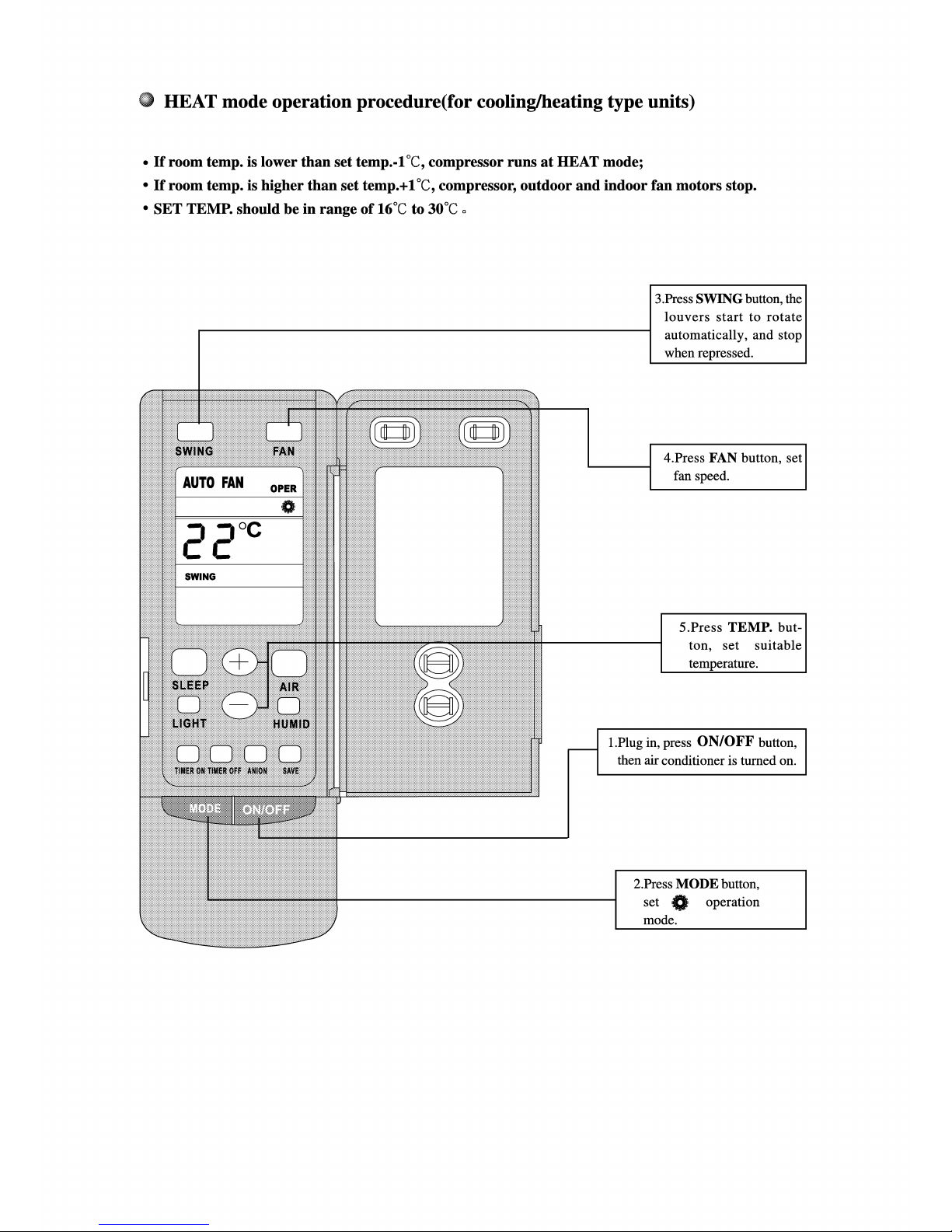
Λειτουργία Θέρμανσης(για τις μονάδες Ψύξης/Θέρμανσης)
• Εάν η θερμοκρασία του χώρου είναι κατά 1°C χαμηλότερη από την ρυθμισμένη θερμοκρασία,
ο συμπιεστής λειτουργεί στην Θέρμανση.
• Εάν η θερμοκρασία του χώρου είναι κατά 1°C υψηλότερη από την ρυθμισμένη θερμοκρασία,
ο συμπιεστής και ο ανεμιστήρας της εσωτερικής/εξωτερικής μονάδας σταματούν.
• Η ρυθμισμένη θερμοκρασία πρέπει να είναι από 16°C έως 30°C.

- 12 -
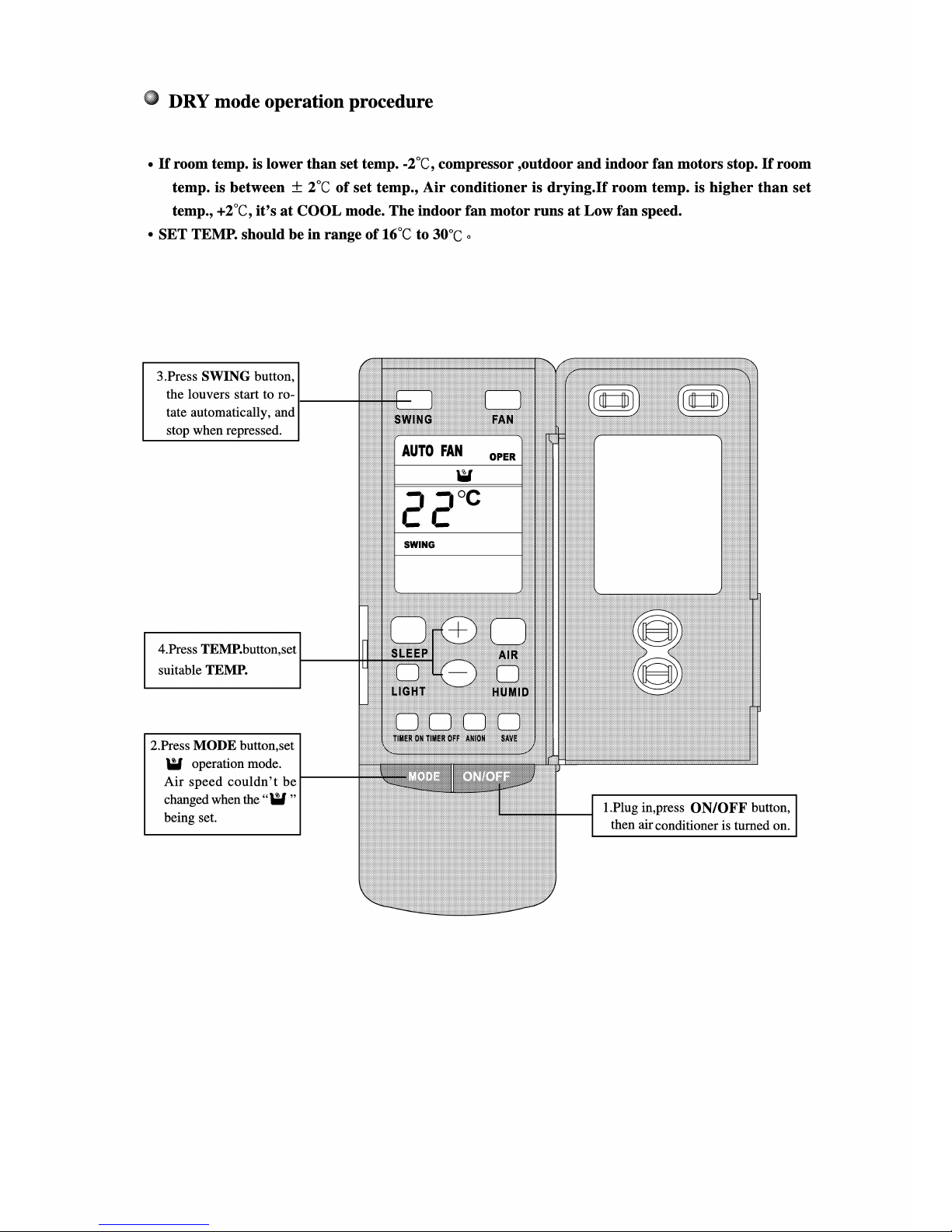
1.Πιέστε το πλήκτρο ON/OFF
και το κλιματιστικό θα ενεργοποιηθεί
3. Πιέστε το πλήκτρο SWING για
να ξεκινήσει η κίνηση των περσίδων.
Ξαναπατήστε το για να σταματήσει
4. Πιέστε το πλήκτρο TEMP και
ορίστε την επιθυμητή θερμοκρασία
2. Πιέστε το πλήκτρο MODE, και
ρυθμίστε τη λειτουργία
Κατά αυτή τη λειτουργία δεν
μπορείτε να ρυθμίσετε την
ταχύτητα του ανεμιστήρα.
Λειτουργία Αφύγρανσης
• Εάν η θερμοκρασία του χώρου είναι κατά 2°C χαμηλότερη από την ρυθμισμένη θερμοκρασία,
ο συμπιεστής και ο ανεμιστήρας της εσωτερικής και της εξωτερικής μονάδας σταματούν.
• Εάν η θερμοκρασία του χώρου είναι ± 2°C από την ρυθμισμένη θερμοκρασία, το κλιματιστικό
αφυγραίνει. Εάν η θερμοκρασία του χώρου είναι κατά 2°C μεγαλύτερη από την ρυθμισμένη,
το κλιματιστικό περνά σε λειτουργία ψύξης και ο ανεμιστήρας τη εσωτερικής μονάδας λειτουργεί
στη χαμηλή ταχύτητα.
• Η ρυθμισμένη θερμοκρασία πρέπει να είναι από 16°C έως 30°C.

- 13 -
Λειτουργία Χρονοδιακόπτη
Πλήκτρο TIMER OFF
Πιέστε αυτό το πλήκτρο
για να ορίσετε την ώρα
απενεργοποίησης σε εύρος
από 30 λεπτά έως 24 ώρες.
Ακύρωση
χρονοδιακόπτη
Πλήκτρο TIMER ON
Πιέστε αυτό το πλήκτρο
για να ορίσετε την ώρα
ενεργοποίησης σε εύρος
από 30 λεπτά έως 24 ώρες.
Ακύρωση
χρονοδιακόπτη

- 14 -
Πλήκτρο MODE
Πιέστε αυτό το πλήκτρο για
να αλλάξετε το πρόγραμμα
λειτουργίας με την ακόλουθη
σειρά:
ή
Πλήκτρο SWING
Πιέζοντας αυτό το πλήκτρο
ξεκινά η αυτόματη κίνηση των
περσίδων. Πιέζοντάς το ξανά
η κίνηση σταματά.
4. Πιέστε το πλήκτρο FAN, για να
ορίσετε την ταχύτητα του ανεμιστήρα.
1.Πιέστε το πλήκτρο ON/OFF
και το κλιματιστικό θα ενεργοποιηθεί
5. Πιέστε το πλήκτρο TEMP και
ορίστε την επιθυμητή θερμοκρασία
Πλήκτρο SLEEP
Πιέστε αυτό το πλήκτρο
για να ενεργοποιήσετε
τη λειτουργία SLEEP.
Ξαναπατήστε το για να την
απενεροποιήσετε.
Λειτουργία Θέρμανσης(για τις μονάδες Ψύξης/Θέρμανσης)
• Όταν η μονάδα λειτουργεί στην ψύξη ή την αφύγρανση, εάν ενεργοποιηθεί η λειτουργία Sleep, η
θερμοκρασία θα ανέβει κατά 1°C σε μία ώρα και κατά 2°C σε δυο ώρες.
• Όταν η μονάδα λειτουργεί στην θέρμανση, εάν ενεργοποιηθεί η λειτουργία Sleep, η θερμοκρασία θα
πέσει κατά 1°C σε μία ώρα και κατά 2°C σε δυο ώρες.

- 15 -
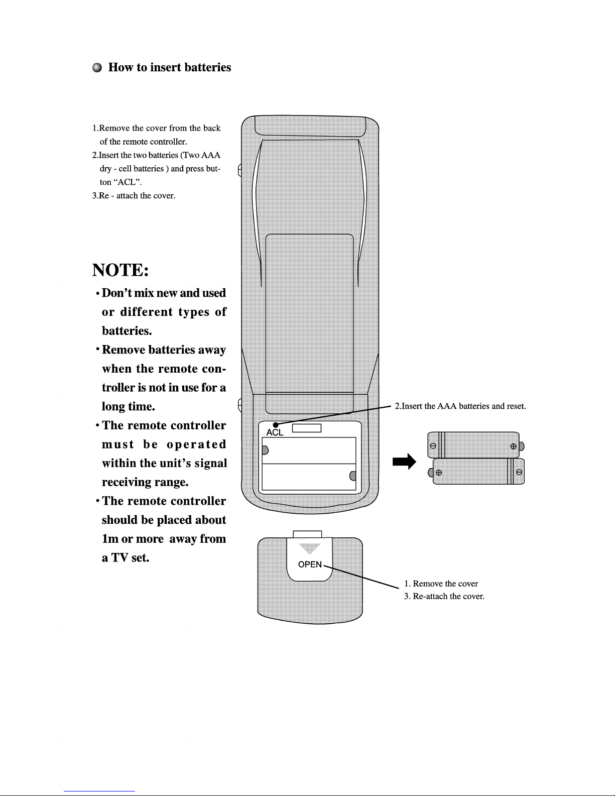
1. Αφαιρέστε το καπάκι από το
πίσω μέρος του τηλεχειριστηρίου
2. Τοποθετήστε 2 μπαταρίες (ΑΑΑ
ξηρού τύπου) και πιέστε το
πλήκτρο “ACL”.
3. Επανατοποθετήστε το καπάκι.
ΣΗΜΕΙΩΣΗ:
• Μην βάζετε παλιές και νέες
μπαταρίες μαζί ή μπαταρίες
διαφορετικού τύπου.
• Αφαιρέστε τις μπαταρίες
όταν το τηλεχειριστήριο δεν
πρόκειται να χρησιμοποιηθεί
για αρκετό καιρό.
• Το τηλεχειριστήριο πρέπει να
χρησιμοποιείται εντός της
εμβέλειας του.
• Το τηλεχειριστήριο πρέπει να
τοποθετηθεί τουλάχιστον ένα
μέτρο μακρυά από την τηλεόραση
1. Αφαιρέστε το καπάκι
3. Τοποθετήστε το καπάκι
2. Τοποθετήστε τις μπαταρίες ΑΑΑ
Πως να τοποθετήστε τις μπαταρίες

16
• Πιέστε το πλήκτρο SWING στο πάνελ ελέγχου για να
επιλέξετε το Swing ή το End Swing, τότε οι περσίδες θα
κινούνται δεξιά-αριστερά ή θα σταματήσουν και η ροή του
αέρα θα έχει σταθερή κατεύθυνση.
• Καθε φορά που πιέζετε το πλήκτρο στην οθόνη εμφανίζεται
η ένδειξη SWING, εάν λειτουργεί ο ανεμιστήρας της
εσωτερικής μονάδας, θα ξεκινήσει η κίνηση των περσίδων,
πατήστε το ξανά και η κίνηση σταματάει και η ένδειξη σβήνει
από την οθόνη.
Ρυθμίστε την κάθετη κατεύθυνση των περσίδων με το χέρι.
Κρατήστε τα δύο άκρα των περσίδων κατά την ρύθμιση.
Κατά την ψύξη ή αφύγρανση ρυθμίστε τις περσίδες ελαφρώς
προς τα πάνω. Κατά την ψύξη ρυθμίστε τις προς τα κάτω.
(Οριζόντια κίνηση
περσίδων)
Ευθεία
ροή
Κατεύθυνση ροής αέρα
1.Κατεύθυνση ροής αέρα δεξιά-αριστερά 2.Κατεύθυνση ροής αέρα πάνω-κάτω
Ροή προς
τα πάνω
Ροή προς
τα κάτω
Κατά την θέρμανση ρυθμίστε την ροή προς τα κάτω
Κατά την ψύξη ρυθμίστε την ροή προς τα πάνω
ΣΥΝΤΗΡΗΣΗ

17
Καθαρισμός της μονάδας
1. Αποσυνδέστε τη μονάδα από το ρεύμα
3. Μην χρησιμοποιείτε οξύ ή αλκαλικά
διαλύματα
3. Μην ρίχνετε νερό στη μονάδα
• Βεβαιωθείτε ότι δεν υπάρχουν εμπόδια
στους αεραγωγούς της εξωτερικής μονάδας.
2. Χρησιμοποιήστε ένα μαλακό
πανί για τον καθαρισμό.
Εάν το εξωτερικό της μονάδας είναι
πολύ βρώμικο, βρέξτε το πανί με
χλιαρό νερό κάτω των 40°C,
στραγγίξτε το πανί και
καθαρίστε τη μονάδα.
Αποσυνδέστε τη μονάδα από το ρεύμα, μόνο όταν το
κλιματιστικό έχει σταματήσει εντελώς την λειτουργία του.
• Βεβαιωθείτε ότι το κλιματιστικό είναι απενεργοποιημένο.
• Αφαιρέστε τη βίδα από την λαβή στην γρίλια εισαγωγής αέρα.
• Τραβήξτε την γρίλια από την λαβή προς τα έξω.
• Το φίλτρο είναι συνδεδεμένο πάνω στη γρίλια, αφαιρέστε το.
• Καθαρίστε το χτυπώντας το ελαφρώς ή με μια ηλεκτρική
σκούπα. Εάν έχει συσσωρευθεί πολλή σκόνη χρησιμοποιήστε
νερό με ένα ουδέτερο απορρυπαντικό, και ξεβγάλτε το.
Στεγνώστε το μετά τον καθαρισμό και επανατοποθετήστε το.
•
Μην στεγνώσετε το φίλτρο εκθέτοντάς το στον ήλιο ή σε
πηγή θερμότητας, αλλιώς θα παραμορφωθεί.
• Το φιλτρο μπορεί να παραμορφωθεί εάν το καθαρίσετε με
ζεστό νερό( 50°C και πάνω).
στραγγίξτε το
πανί πρίν τον
καθαρισμό
Λαβή
Γρίλια εισαγωγής αέρα
Καθαρισμός του φίλτρου
Το φίλτρο πρέπει να καθαρίζεται
κάθε 2 εβδομάδες
Αφαίρεση του φίλτρου
Καθαρισμός
Σημείωση
Φροντίδα και Συντήρηση
Τα εμπόδια θα προκαλέσουν
βλάβη στη μονάδα.

18
Εάν το κλιματιστικό σας δεν λειτουργεί σωστά, ελέγξτε τα παρακάτω πριν ζητήσετε βοήθεια. Εάν ελέγξετε τα ακόλουθα
σημεία και το κλιματιστικό σας συνεχίζει να μην λειτουργεί σωστά, επικοινωνήστε με το τμήμα επισκευών για να το ελέγξει.
Το κλιματιστικό δεν
ενεργοποιείται
Το κλιματιστικό σταματάει
αμέσως μετά την εκκίνηση
και αναγράφεται ή ένδειξη
“Ε1”
Το κλιματιστικό σταματάει
αμέσως μετά την εκκίνηση
και αναγράφεται ή ένδειξη
“Ε2”
Το κλιματιστικό σταματάει
αμέσως μετά την εκκίνηση
και αναγράφεται ή ένδειξη
“Ε3”
Το κλιματιστικό σταματάει
αμέσως μετά την εκκίνηση
και αναγράφεται ή ένδειξη
“Ε4”
Η ένδειξη θερμοκρασίας
δείχνει 0°C και δεν
δουλεύει η ψύξη.
Χαμηλή απόδοση
Ψύξης
Χαμηλή απόδοση
Θέρμανσης
1. Δεν έχει ρεύμα
2. Ασφάλεια διαρροής ρεύματος
3. Χαμηλή τάση
4. Το πλήκτρο λειτουργίας είναι
απενεργοποιημένο.
5. Πρόβλημα στο κύκλωμα ελέγχου
1. Φραγμένος συμπυκνωτής
2. Πρόβλημα στο κύκλωμα ελέγχου
3. Ψύξη ενώ η εξωτερική θερμοκρασία
είναι πάνω από 43°C
4. Υψηλή πίεση στην σωλήνωση
1. Δεν λειτουργεί ο ανεμιστήρας της εσωτερικής
μονάδας ή έιναι φραγμένη η εξωτερική μονάδα
2. Η εσωτερική θερμοκρασία είναι κάτω από 18°C
3. Κομμένο καλώδιο του αισθητήρα θερμοκρασίας
του στοιχείου
4. Ο αισθητήρας θερμοκρασίας δεν είναι στη
θέση του
5. Πρόβλημα στο κύκλωμα ελέγχου
6. Ηλεκτρική διαρροή στον πυκνωτή
1. Κομμένο καλώδιο στον αισθητήρα
εσωτερικής θερμοκρασίας
2. Ο αισθητήρας εσωτερικής θερμοκρασίας
δεν είναι στη θέση του
3. Ηλεκτρική διαρροή στον πυκνωτή
1. Φραγμένο ή βρώμικο φίλτρο
2. Πολλοί άνθρωποι ή πηγές θερμότητας
στο χώρο.
3. Ανοιχτό παράθυρο ή πόρτα
4. Φραγμένοι αεραγωγοί
5. Υψηλή ρυθμισμένη θερμοκρασία
6. Διαρροή ψυκτικού
7. Βλάβη στον αισθητήρα εσωτερικής
θερμοκρασίας.
1. Φραγμένο ή βρώμικο φίλτρο
2. Ανοιχτό παράθυρο ή πόρτα
3. Χαμηλή ρυθμισμένη θερμοκρασία
4. Διαρροή ψυκτικού
5. Εξωτερική θερμοκρασία μικρότερη από -5°C
6. Πρόβλημα στο κύκλωμα ελέγχου
1. Συνδέστε την παροχή ρεύματος
2. Επικοινωνήστε με το τμήμα επισκευών
3. Επικοινωνήστε με ηλεκτρολόγο
4. Πιέστε ξανά το πλήκτρο
5. Επικοινωνήστε με το τμήμα επισκευών
1. Απομακρύνετε το εμπόδιο
2. Επικοινωνήστε με το τμήμα επισκευών
3. Τοποθετήστε την εξ. μονάδα σε σκιερό
μέρος
4. Επικοινωνήστε με το τμήμα επισκευών
1. Επικοινωνήστε με το τμήμα επισκευών
2. Ελέγξτε εάν πρέπει να ανάψετε το
κλιματιστικό.
3. Επικοινωνήστε με το τμήμα επισκευών
4.Τοποθετήστε τον αισθητήρα στη θέση
του
5. Επικοινωνήστε με το τμήμα επισκευών
6. Επικοινωνήστε με το τμήμα επισκευών
1. Επικοινωνήστε με το τμήμα επισκευών
2. Τοποθετήστε τον αισθητήρα στη θέση του
3. Επικοινωνήστε με το τμήμα επισκευών
1. Καθαρίστε το φίλτρο
2. Απομακρύνετε τις πηγές θερμότητας
3. Κλείστε τα παράθυρα και τις πόρτες
4. Απομακρύνετε τα εμπόδια
5. Ρυθμίστε χαμηλότερη θερμοκρασία
6. Επικοινωνήστε με το τμήμα επισκευών
7. Αντικαταστήστε τον αισθητήρα
1. Καθαρίστε το φίλτρο
2. Κλείστε τα παράθυρα και τις πόρτες
3. Ρυθμίστε χαμηλότερη θερμοκρασία
4. Επικοινωνήστε με το τμήμα επισκευών
5. Επηρεάζεται η θέρμανση
6. Επικοινωνήστε με το τμήμα επισκευών
Πρόβλημα Πιθανά αίτια Λύση
Έλεγχος προβλημάτων
1.Διαρροή ψύκτικού
2.Πρόβλημα στο κύκλωμα ελέγχου
1.Επικοινωνήστε με το τμήμα επισκευών
2.Επικοινωνήστε με το τμήμα επισκευών
1.Διαρροή ψυκτικού
2.Πρόβλημα στο κύκλωμα ελέγχου
3.Κομμένο καλώδιο στον αισθητήρα
4.Πολύ χαμηλή τάση
1.Επικοινωνήστε με το τμήμα επισκευών
2.Επικοινωνήστε με το τμήμα επισκευών
3.Επικοινωνήστε με το τμήμα επισκευών
4.Επικοινωνήστε με το τμήμα επισκευών

19
ΕΓΚΑΤΑΣΤΑΣΗ
Ηλεκτρολογική συνδεσμολογία
Πριν την εγκατάσταση διαβάστε προσεκτικά το εγχειρίδιο
Ακολουθήστε πιστά τις οδηγίες για την εγκατάσταση της εσωτερικής μονάδας και της διασωλήνωσης της
Πρώτα συνδέστε την καλωδίωση της εξωτερικής μονάδας και μετά της εσωτερικής. Όταν τελειώσουν οι
εργασίες καλωδίωσης και διασωλήνωσης, συνδέστε τη μονάδα στο ρεύμα.
Ο σχεδιασμός της μονάδας μπορεί να αλλάξει χωρίς προηγούμενη ειδοποίηση.
Παράδειγμα καλωδίωσης
Μοντέλο
Παροχή ρεύματος
Εισαγώμενη ισχύς Ασφάλεια αέρα
Καλωδιώσεις
Διατομή καλωδίου
παροχής (mm2)
Ελάχιστη διατομή καλωδίου
σύνδεσης εσ./εξ. μονάδας (mm2)
Σημείωση:
1. Δώστε προσοχή στον περιβάλλοντα χώρο (π.χ. ηλιοφάνεια, βροχή κλπ.)
2. Εάν υπάρχει πτώση τάσης, χρησιμοποιήστε μεγαλύτερα καλώδια παροχής
3. Πρέπει να συνδεθεί η γείωση ση εσωτερική και στην εξωτερική μονάδα.
4. Τα δεδομένα σε αυτόν τον πίνακα είναι αναφορικά, εκτελέστε την καλωδίωση σύμφωνα με τους εθνικούς
κανονισμούς καλωδίωσης.
25A
2.5/1.5
/
380
RFI-66B/RFO-66B
-415V 3N~50Hz
Πρέπει να χρησιμοποιηθεί ξεχωριστό κύκλωμα παροχής ρεύματος.
Το κύκλωμα πρέπει να εγκατασταθεί από εξειδικευμένο τεχνικό.
Ακολουθήστε το παρακάτω διάγραμμα καλωδίωσης, οι βίδες πρέπει να τοποθετηθούν σφιχτά.
Το καλώδιο επικοινωνίας και το καλώδιο παροχής ρεύματος πρέπει να τοποθετηθούν έτσι ώστε να μην έρχονται σε επαφή.
Συνδέστε τα καλώδια φάσης σωστά. Εάν η σύνδεση είναι λάθος το κλιματιστικό θα σταματήσει τη λειτουργία του αυτόματα,
σε αυτή τη περίπτωση, αλλάξτε τη θέση των καλωδίων 2 και 3 φάσεων και το κλιματιστικό θα λειτουργήσει σωστά.
Για μονάδες με αντλία θερμότητας (3φασική )
Γειώστε σωστά τις μονάδες αλλίως μπορεί να υπάρχουν παρεμβολές
Παροχή ρεύματος
Κεντρικός διακόπτης
Διαθέσιμο στο εμπόριο
Παροχή ρεύματος
για την εσ. μονάδα
Παροχή ρεύματος
για την εξ. μονάδα
Εσωτερική
μονάδα
Γείωση
Γείωση
Καλώδιο σήματος
Εξωτερική
μονάδα

20
Παρατηρήσεις για σωλήνωση
Οι σωλήνες για ψυκτικό και αποστράγγιση θα πρέπει να μονωθούν ώστε να αποφευχθούν πάγος και σταγόνες.
Η εσωτερική και εξωτερική μονάδα διαθέτουν σύνδεση εκχείλωσης.
Η σωλήνα ψυκτικού όπως φαίνεται παρακάτω χρησιμοποιείται για τη σύνδεση εσωτερικής και εξωτερικής μονάδας.
Σημείωση: Μην λυγίζετε την εύκαμπτη σωλήνα πίσω και μπροστά παραπάνω από 3 φορές.
Σημείωση: Μονώστε όλα τα εκτεθειμένα μέρη των συνδέσμων σύνδεσης εκχείλωσης και της σωλήνας ψυκτικού.
2. Όταν αγοράζετε οι ίδιοι χαλκοσωλήνα
Ελέγξτε τη βαλβίδα της εξωτερικής μονάδας να είναι κλειστή (στη θέση αυτή δεν λειτουργεί). Μετά την ένωση της
σωλήνας ψυκτικού στην εσωτερική και εξωτερική μονάδα, βγάλτε από το στόμιο την βαλβίδας ελέγχου χαμηλής
πίεσης της εξωτερικής μονάδας. Μετά, τοποθετήστε ξανά το παξιμάδι στο και κουμπώστε.
3. Αφότου ολοκληρώσετε τα βήματα 1 και 2, η βαλβίδα ελέγχου της εξωτερικής μονάδας πρέπει να είναι πλήρως ανοιχτή
ώστε να μην υπάρχει εμπόδιο ανάμεσα στην εσωτερική και εξωτερική σωλήνα ψυκτικού.
Σημείωση: πριν σφίξετε το παξιμάδι στην σύνδεση σωλήνας εκχείλωσης, παρακαλούμε εφαρμόστε λίγο λάδι ψυκτικού
υγρού στο τέρμα της σωλήνας και του συνδέσμου.
1. Συνδέστε τη σωλήνα
Ελέγξτε τη βαλβίδα εξωτερικής μονάδας ότι είναι κλειστή (δεν δουλεύει σε αυτή τη θέση). Κάθε φορά που συνδέετε,
αφαιρέστε το κάλυμμα από τη βαλβίδα ελέγχου και ενώστε τη σωλήνα σύνδεσης εκχείλωσης αμέσως (μέσα σε 5 λεπτά),
αλλιώς σκόνη, υγρασία και άλλα μικρά πράγματα μπορεί να εισχωρήσουν μέσα στη σωλήνα και να προκαλέσουν
σφάλματα.
Αναφορικά με την εύκαμπτη σωλήνα
Το μέρος της εύκαμπτης σωλήνας πρέπει να χρησιμοποιηθεί στην εσωτερική πλευρά.
Η γωνία της εύκαμπτης σωλήνας δεν πρέπει να ξεπερνά τις 90
ο
.
Είνια προτιμότερο το λύγισμα να γίνει στη μέση της σωλήνας και η ακτίνα λυγίσματος όσο μεγαλύτερη τόσο το καλύτερο.
Μην λυγίζετε την εύκαμπτη σωλήνα πάνω από 3 φορές.
Όταν λυγίζετε τη σωλήνα
Κόψτε μέρος από τη μόνωση στο μέρος λυγίσματος (και τυλίξτε μετά το λύγισμα με ταινία πολυαιθυνελίου).
Κάντε λύγισμα με ακτίνα όσο μεγαλύτερη γίνεται ώστε να μην είναι ίσια η σωλήνα αλλά και να μην σπάσει.
Εσωτερική μονάδα
Εύκαμπτη σωλήνα
19 1
Σύνδεση εκχείλωσης
12 1
Εξωτερική
μονάδα
Ταινία Πολυαιθυλενίου
Μονωτικό Κάλυμμα
Χαλαρώστε τη τυλιγμένη σωλήνα
Σφίξτε το τέρμα της σωλήνας
Λυγίστε τη σωλήνα με τον αντίχειρα
Ελάχιστη ακτίνα: 100mm

21
Εγκατάσταση εσωτερικής μονάδας
1. Επιλέξτε τοποθεσία 2. Εγκατάσταση σωλήνων
• Εκεί που δεν επηρεάζεται από τον εξωτερικό αέρα.
• Εκεί που δεν εμποδίζεται η εισαγωγή και εξαγωγή αέρα.
• Εκεί που μπορεί εύκολα η σωλήνα ψυκτικού να οδηγηθεί έξω.
• Εκεί που ο αέρας από το κλιματιστικό μπορεί να φτάσει σε κάθε μέρος
του δωματίου.
• Εκεί που δεν υπάρχει πολύ υγρασία και δεν μπορεί να πεταχτεί λάδι
πάνω.
• Εκεί που δεν υπάρχει διαροοή εύφλεκτου αερίου.
• Επιλέξτε σταθερό και στιβαρό έδαφος.
• Αφήστε αρκετό χώρο για εγκατάσταση και συντήρηση.
• Αφαιρέστε την γρίλια εισαγωγής αέρα
• Πριν τη καλωδίωση και τη σωλήνωση, παρακαλούμε αφαιρέστε τη
γρίλια εισαγωγής αέρα.
• Αφαιρέστε τη βίδα από τη γρίλια.
• Ανοίξτε τη γρίλια τραβώντας την από το χερούλι.
• Αφαιρέστε την αλυσίδα και βγάλτε τη γρίλια.
3. Εγκαταστήστε σωλήνα αποστράγγισης
Βεβαιωθείτε ότι η σωλήνα αποστράγγισης οδηγεί στην εξωτερική πλευρά. (μεριά απόλυσης)
Χυτεύστε τη σωλήνα αποστράγγισης και προσαρμόστε ταινία γύρω από αυτή.
Αν η σωλήνα αποστράγγισης χρειάζεται να οδηγηθεί εσωτερικά, παρακαλούμε τυλίξτε την με μονωτικό υλικό (τουλάχιστον 9mm
λεπτό) και μετά τυλίξτε το με ταινία ώστε να αποφύγετε την εισχώρηση αέρα στη σωλήνα που μπορεί να προκαλέσει πήξη.
Μετά την ολοκλήρωση της σύνδεσης, ελέγξτε αν το νερό μπορεί να αποβληθεί σωστά και αν υπάρχει τυχόν διαρροή.
>30cm
>4cm
>5cm
>10cm
(Μέρος σωλήνα:30cm ελαχ..)
Μπροστά
>200cm
>10cm
(Μέρος σωλήνα:
30cm ελαχ.)
Αλυσίδα
Βίδα
Λαβή
Σωλήνα Αποστράγγισης
19 1
Σωλήνα Ψυκτικού
12 1
Σύνδεση εκχείλωσης Σύνδεση εκχείλωσης
Σωλήνα αποστράγγισης εσωτερικής μονάδας
Χύτευση σωλήνα αποστράγγισης
Σωλήνα αποστράγγισης
Τυλίξτε με ταινία

22
Καλώδια σήματος
(2) Για μοντέλα με αντλία θερμότητας (5 φασική)
Τερματικό κουτί στην εσωτερική μονάδα
Παροχή ρεύματος
Παροχή ρεύματος
Τερματικό κουτί στην εξωτερική μονάδα
Σημείο επαφής
καλωδίου
L1 L2
L3 N
L1 L2
L3 N
Ασφάλεια
Μοντέλο
RFI-66B/RFO-66B
25A
Καλωδίωση εσωτερικής μονάδας
• Αφαιρέστε τη βίδα από το κάλυμα του ηλεκτρολογικού πίνακα ώστε να τον ανοίξετε.
• Κάντε τη καλωδίωση όπως φαίνεται παρακάτω και μετά προσαρμόστε με σύνδεσμο καλωδίων.
Βίδα
Κάλυμμα ηλεκτρολογικού πίνακα

23
Εγκατάσταση εξωτερικής μονάδας
1. Επιλέξτε τοποθεσία
Σημείωση:
Η εξωτερική μονάδα πρέπει να εγκατασταθεί
σε σταθερή και στιβαρή βάση ώστε να αποφευχθεί ο θόρυβος και οι δονήσεις.
Η εξαγωγή αέρα δεν πρέπει να εμποδίζεται.
Σε παραθαλάσσιες περιοχές, περιοχές με
μεγάλο υψόμετρο ή δυνατό αέρα, παρακαλούμε εγκαταστήστε τη μονάδα κολλητά στον
τοίχο ή χρησιμοποιήστε προστατευτικό.
Εγκαταστήστε τη μονάδα με καλό εξαερισμό
αντί για κλειστούς χώρους.
Μέγεθος οπής εγκατάστασης: 572x327mm.
2. Σύνδεση ψυκτικής σωλήνας
Σύνδεσμος σφιξίματος
Ταιριάξτε σωληνώσεις
Βιδώστε το παξιμάδι με το χέρι και
μετά σφίξτε με γαλλικό κλειδί
(δείτε σχήμα παρακάτω).
Προσέξτε να μην γυρίσετε υπερβολικά
αλλιώς το παξιμάδι μπορεί να καταστραφεί.
Διάμετρος
(mm)
Ροπή
(N m)
12 45-50
19 70-75
Εκκένωση (με εξαγωνικό κλειδί)
Όγκος
ψυκτικού
Ίδια τιμή με
το ταμπελάκι
Ίδια τιμή με το
ταμπελάκι +30g/m
(επιπλέον 30g για
κάθε επιπλέον μέτρο
της σωλήνας)
Χρήση του
ψυκτικού της
εξωτερικής
μονάδας.
Χρήση
αντλίας
κενού
1. Δείτε το τμήμα για την αντλία κενού ή
την δεξαμενή ψυκτικού
2. Συμπληρώστε το ψυκτικό σύμφωνα με
τα παραπάνω. Εάν η μονάδα πρόκειται
να μετακινηθεί, εκκενώστε το ψυκτικό
υγρό με αντλία κενού ή με δεξαμενή
ψυκτικού.
• Όταν χρησιμοποιείτε το ψυκτικό της
εξωτερικής μονάδας:
1. Σφίξτε επαρκώς τα μπουλόνια A,B,C,D
2. Αφαιρέστε το κάλυμμα από την βαλβίδα Α
3. Στρίψτε το στέλεχος της βαλβίδας Β ώστε
να ανοίξει, με ένα κλειδί ροπής, και ταυτόχρονα
κρατήστε το στέλεχος της βαλβίδας Α με ένα
κατσαβίδι ώστε να εξέλθει το αέριο.
Μετά από 15 δευτερόλεπτα εκκένωσης και
μόλις εμφανιστεί ψυκτικό υγρό, κλείστε τη
βαλβίδα και σφίξτε το κάλυμμα.
4. Ανοίξτε πλήρως τις βαλβίδες υγρού και
αερίου, σφίξτε το κάλυμμα, και ελέγξτε για
διαρροές (με σαπουνόνερο ή με ανιχνευτή
διαρροής) στις ενώσεις των σωλήνων μεταξύ
εσωτερικής και εξωτερικής μονάδας.
Όταν χρησιμοποιείτε αντλία κενού
1. Συνδέστε τον αγωγό πλήρωσης
της βαλβίδας πολλαπλής στην
βαλβίδα πλήρωσης χαμηλής πίεσης.
(οι βαλβίδες υψηλής και χαμηλής
πίεσης πρέπει να είναι κλειστές.)
2. Συνδέστε τον αγωγό πλήρωσης
με την αντλία κενού.
3. Ανοίξτε πλήρως την βαλβίδα LO
της βαλβίδας πολλαπλής.
4. Ενεργοποιήστε την αντλία κενού
για την εκκένωση. Αρχικά χαλαρώστε
τη βαλβίδα χαμηλής πίεσης για να
ελέγξετε εάν υπάρχει αέρας μέσα.
(η βαλβίδα της αντλίας κενού θα
αλλάξει από - στο 0). Τότε σφίξτε
αυτή τη βαλβίδα.
5. Μετά το τέλος της εκκένωσης,
κλείστε την βαλβίδα Lo της βαλβίδας
πολλαπλής για να σταματήσει η
αντλία κενού. Συνεχίστε την εκκένωση
ώστε το πολύμετρο της βαλβίδας
πολλαπλής να δείξει -1.0x10
5
pa
(-76cmHg).
6. Ανοίξτε πλήρως τις βαλβίδες high/low
7. Αφαιρέστε τον αγωγό πληρώτητας
από την βαλβίδα low.
8. Σφίξτε το κάλυμμα της βαλβίδας low.
Εκκένωση
Μήκος
σωλήνα
5m
5-15m
Εξωτερική μονάδα
Πλευρά αερίου
Εσωτερική μονάδα
βαλβίδα ελέγχου
Συνδεση σωληνώσεων
A
B
C
D
12mm
19mm
-76cmHg
Βαλβίδα πολλαπλής εισαγωγής
Μανόμετρο
Μανόμετρο
Λαβή
χαμηλής πίεσης
Σωλήνας φόρτισης
Βαλβίδα
χαμηλής πίεσης
Αντλία κενού
Λαβή
υψηλής πίεσης
Σωλήνας
φόρτισης
Παξιμάδι βαλβίδας
Κατά την χρήση της βαλβίδας ελέγχου προσέξτε:
Ανοίξτε την βαλβίδα έως το όριο ασφάλισης
και όχι περισσότερο
Σφίξτε το κάλυμμα με κλειδί
Όριο ασφάλισης
Κάλυμμα
Στέλεχος βαλβίδας
Βαλβίδα

24
3.Καλωδίωση
Αφαιρέστε το μπροστινό πάνελ.
Ανοίξτε εξωτερική οπή καλωδιώσεων και ενσωματώστε έναν δακτύλιο για τα καλώδια.
Οδηγήστε το καλώδιο σύνδεσης από το τερματικό κουτί της εξωτερικής μονάδας, και προωθήστε το στην
εξωτερική οπή καλωδιώσεων και στην εσωτερική και μετά συνδέστε με το εσωτερικό τερματικό κουτί.
Ενώστε τα καλώδια όπως φαίνεται παρακάτω και μετά προσαρμόστε το με σφιγκτήρα καλωδίων.
Δοκιμαστική λειτουργία
Αφότου ολοκληρώσετε
τον έλεγχο για διαρροή,
ξεκινήστε τον δοκιμαστικό
έλεγχο.
Ψύξη
Ρυθμίστε λειτουργία ψύξης.
Δείτε το εγχειρίδιο χρήστη για λεπτομέρειες.
3- λεπτη προστασία
Αν η μονάδα σταματήσει, χρειάζεται
3 λεπτά να επανεκκινηθεί.
3~220V 60Hz
Εξωτερικά καλώδια σήματος
Καλώδια Σήματος
Καλώδια Σήματος
Καλώδιο σύνδεσης ρεύματος
Καλώδιο ρεύματος
Εξωτερική οπή καλωδίωσης
Οπίσθιο πάνελ
Μπροστινό πάνελ
Τερματικό κουτί

25
Εγκαταστήστε σύρμα προστασίας κλίσης
Σημείωση:
Για να αποφύγετε οποιοδήποτε ατύχημα από τη κλίση της εξωτερικής μονάδας, παρακαλούμε εγκαταστήστε
προστατευτικό σύρμα κλίσης.
Βήματα εγκατάστασης:
Αφαιρέστε τη βίδα από το κάλυμμα της εσωτερικής μονάδας (Εικ 1)
2. Βγάλτε το προστατευτικό από το καλώδιο και βάλτε μέσα στη θήκη που υπάρχει στην οπή και κουμπώστε το με τις βίδες. (Εικ. 2)
3.Στερελωστε την άλλη άκρη του σύρματος στον τοίχο χρησιμοποιώντας βίδα (ST4.2X38)
Βγάλτε τη βίδα
οπή προστασίας
Στρεώστε αυτή την άκρη στον τοίχο
Βάλτε αυτή την άκρη
στην οπή και στερεώστε.
Τοίχος
Εσωτερική μονάδα
Εικ 1
Εικ 2
To παραπάνω σχήμα είναι για επεξηγηματικούς σκοπούς μόνο, η εσωτερική μονάδα μπορεί να διαφέρει.

Ενεργοποιήστε την εγγύηση σας...
σε
5
απλά
Συνδεθείτε στο site της
στον ακόλουθο σύνδεσµο
http://www.inventoraircondition.gr/
egiisi-inventor/
Επιλέξτε τον τύπο του προϊόντος
(κλιµατιστικό ή συσκευή) για το
οποίο θα ενεργοποιηθεί η εγγύηση
Συµπληρώστε τα απαιτούµενα
στοιχεία (κατόχου, εµπόρου και
συσκευής) και πατήστε αποστολή
Επιλέξτε την εγγύηση
που αντιστοιχεί στο προϊόν
που έχετε στην κατοχή σας
Θα λάβετε επιβεβαιωτικό
µήνυµα στο e-mail σας για
την ενεργοποίηση της εγγύησης
Για την υποβολή
ηλεκτρονικών εγγυήσεων
πληκτρολογήστε
την παρακάτω διεύθυνση
https://www.inventoraircondition.gr/egiisi-inventor
Σκανάρετε εδώ
για τα έντυπα
των εγγυήσεων
Inventor

1
CUPRINS
2
3
4
5
16
17
18
19
20
21
23
24
25
7
Note inainte de folosire
Structura
Mentenanta
Structura
Modele si specificatii
Panoul de control
Directionarea fluxului de aer
Intretinere
Depanare
Cablajul
Note privind tubulatura.
Instalarea unitatii interioare
Instalarea unitatii exterioare
Instalarea cablului protector
Testarea
Instalarea
Telecomanda

2
NOTE INAINTE DE FOLOSIRE
Cerinte electrice
Limitele de temperatura
Modul de
functionare
Incalzire
Temperatura Temperatura interioara
27°C
(nivel sczaut al umiditatii) 24°C
(nivel sczaut
al umiditatii)
(nivel sczaut
al umiditatii)
/
18°C
(nivel crescut
al umiditatii)
(nivel crescut
al umiditatii)
-5°C / -6°C
20°C (nivel sczaut al umiditatii)
Temperatura exterioara
Max.
Min.
AVERTIZMENT
ATENTIONARE
1. Capacitatea retelei electrice trebuie sa fie de cel putin 10kw, sectiunea firelor de cupru trebuie sa fie de cel putin 2.5
mm2.
2. Aparatul trebuie impamantat. Impamantarea va fi conectata la sistemul de impamantare al cladirii si nu la conductetele
de gaz sau apa.
3. Lucrarile electrice vor fi efectuate doar de catre un tehnician autorizat si in conformitate cu normele si reglementarile in
vigoare.
4. Circuitul electric va include protectii la scurgeri de curent si un comutator.
5. Opriti alimentarea cu energie electrica atunci cand nu folositi aparatul.
Cerinte privind siguranta:
• Cititi cu atentie manualul de utilizare inainte de a folosi acest aparat si contactati departamentul de servic al magazinul
vanzator pentru mai multe informatii.
• Acest aparat va fi folosit doar in situatilile descrise in acest manual.
• Nu depozitati lichide sau gaze inflamabile in apropierea acestui aparat! Pericol de explozie/incendiu!
• Acest aparat nu foloseste aer proaspat (din exterior). Atunci cand folositi si un incalzitor pe combustibil
lichid sau gazos, lasati usa/fereastra deschisa. Incalzitorul consuma oxigenul din incapere si calitatea
aerului va scadea.
• Pentru a porni sau opri aparatul, folositi doar butonul ON/OFF si nu faceti acest lucru direct
de la reteaua de alimentare cu energie electrica.
• Nu introduceti obiecte in grilele de admisie/evacuare a aerului.
• Copiilor nu le va fi permis sa opereze aparatul de aer conditionat.
• In cazul in care, in incapere, se afla copii sau persoane bolnave, va recomandam sa ajustati
temperatura aparatului.

3
ΔΟΜΗ
Evacuare aer
Unitate interioara
Unitate exterioara
Conducta
scurgere
Conducte de legatura
Evacuare aer
Evacuare aer
Gura evacuare
Afisaj
Panou frontal
Admisie aer
Admisie aer
Gura admisie aer

4
Model si caracteristici
Functii
Racire/Incalzire (W)
Capacitate incalzire (W)
Alimentare electrica
Putere de intrare (W)
Debit aer (m3/h)
Refrigerant
Zgomot (unitate interioara/
exterioara) dB(A)
Zona climatica
Rezistenta apa
Izolatie
Greutate (unitate/
exterioara)(kg)
Dimensiuni (unitate interioara
/exterioara) (LxIxA) (mm)
Μοντέλο
RFI-66B /RFO-66B
6400/6200(9700)
16000
18000(21500)
380-415 V 3N ~ 50H z
2000
58/63
T1
IP24
I
60/115
Unitate interioara: 540x1750x380
Unitate exterioara: 950x1250x412
Racire/Incalzire
R410A 5.0
Toate informatiile de mai sus pot fi schimbate fara o notificare prealabila. Caracteristicile aparatului dvs. vor fi afisate pe
placuta de identificare.

5
Afisajul LCD al aparatului de aer conditionat de tip coloana
Tasta SWING -
Puteti alege modul de
oscilare a fluxului de aer
Tasta FAN SPEED
permite alegerea vitezei ventilatorului.
Alegeti intre modurile
AUTO/LO/MED/HIGH
TASTA MODE
permite alegerea modului
de functionare:
AUTO/COOL/DRY/FAN/HEAT
Tasta ON/OFF
apasati aceasta tasta
pentru a porni/opri aparatul.
Afisaj LCD
Cand aparatul se afla in modul OFF, tasta
TIMER va fi folosita pentru a programa
aparatul sa porneasca la o anumita ora. La
fiecare apasare a tastei, intervalul va fi
ajustat cu 0.5 ore (in intervalul 0.5-24H). La
ora stabilita, aparatul va porni cu setarile
implicite. Pentru a programa oprirea aparatului la o anumita ora repetati acelasi procedeu
cand aparatul este pornit.
Tastele SET TEMP - permit alegerea
temperaturii de functionare. La fiecare
apasare a butonului , temperatura va
scadea cu 1 grad. Temperatura va creste cu
un grad la fiecare apasare a butonului .
Temperatura incaperii poate fi reglata in
intervalul 16-30 grade celsius. In timpul
functionarii normale, daca veti apasa ambele
butoane in acelasi timp, panoul de control va
fi blocat. Deblocarea se va face apasand
aceleasi 2 butoane in acelasi timp.
PANOUL DE CONTROL

6
FUNCTIILE SPECIALE
Functia TEST
De fiecare data cand unitatea este pornita dar nu primeste semnal de la taste:
(1) Apasati tasta SET TEMP pentru a intra fortat in modul racire. Compresorul va porni si aparatul va functiona
in modul de oscilare a fluxlui de aer automat. Ventilatoarele unitatilor interioare si exterioare for functiona la
viteza cea mai mare iar ecranul LCD va afisa toate simbolurile. Dupa 5 minute, aparatul se va opri si va intra in
modul normal de standby.
(2) Apasati tasta SET TEMP pentru a intra fortat in modul incalzire. Compresorul si incalzitorul electric auxiliar
vor porni. Aparatul va functiona in modul de oscilare a fluxlui de aer automat si ventilatoarele unitatilor interioare si exterioare for functiona la viteza cea mai mare iar ecranul LCD va afisa toate simbolurile. Dupa 5 minute,
aparatul se va opri si va intra in modul normal de standby.
Functia de protectie a compresorului:
Orice mod de functionare ati selecta, compresorul va avea nevoie de 3 minute pentru a reporni dupa ce a fost
oprit. Daca nu ati schimat modul de functionare, compresorul va functiona 6 minute pana va putea fi oprit.
Compresorul se va opri 3 minute la schimbarea modurilor.
Functia de blocare a panoului de control :
In timpul functionarii normale a aparatului, apasati tastele SET TEMP si , in acelasi timp, pentru a bloca
panoul central. Apasand inca odata tastele, veti debloca panoul de central.

- 7 -
Folosirea telecomenzii
Butonul SWING.
La apasarea butonului,
flapsurile vor oscila
automat. Apasati inca o
data butonul pentru a opri
oscilarea.
Butonul TEMP
Apasand butonul “+” veti
creste temperatura cu 1
grad celsius. La apasarea
butonului “-”, temperatura
va scadea cu 1 grad
celsius.
In modul de functionare
COOL, DRY, HEAT,
temperatura poate fi reglata
in intervalul 16-30 grade
celsius.
Butonul MODE.
Apasand butonul, puteti
selecta modul de functionare in urmatoarea ordine:
Butonul ON/OFF
Acest buton il veti folosi
pentru pornirea/oprirea
unitatii.
Butonul FAN
Apasati acest buton pentru a
putea seta viteza ventilatorului
conform imaginii de mai jos:
Modul COOL (racire)
Modul DRY (dezumidificare)
Modul FAN (functionarea
ventilatorului)
Modul HEAT (incalzire)
Denumirea si descrierea functiilor butoanelor
Nota:
• Asigurati-va ca nu exista elemente care pot intrerupe transmiterea semnalului
intre telecomanda si unitate.
• Nu trantiti si nu aruncati telecomanda
• Nu lasati telecomanda in bataia luminii solare sau in locuri foarte calde.
De asemenea, evitati contactul lichidelor cu telecomanda.

- 8 -
Denumirea si functiile butoanelor (capacul deschis)
dezactivarea
temporizatorului
dezactivarea
temporizatorului
NOTA: Functiile butoanelor disponibile cu modelele descrise
in acest manual sunt descrise mai jos.
Displayul LCD va fisa functiile
setate
Butonul SLEEP
Apasatia cest buton pentru a
activa functia SLEEP. Apasati
inca o data acest buton pentru
a dezactiva functia.
Butonul TIMER OFF
In timpul functionarii, apasand
acest buton, veti putea
programa temporizatorul (in
intervalul 0.5-24H), pentru a
opri unitatea automat la ora
stabilita.
Butonul TIMER ON
Atunci cand aparatul este
oprit, apasati acest buton
pentru a programa pornirea
automata a aparatului, in
intervalul 0.5-24H.
Butonul Light
Apasand acest buton veti porni
iluminarea telecomenzii. Apasati
inca o data pentru a o opri.

- 9 -
1. Butonul ON/OFF porneste/opreste unitatea
2. In functie de temperatura incaperii,
aparatul poate seta automat modul pentru
a obtine cel mai bun
rezultat.
Modul de functionare AUTO
• In timpul functionarii in modul AUTO, temperatura standard este de 26 de
grade pentru modul HEAT (incalzire), 20 grade pentru modul COOL
(racire) si 24 de grade pentru modul DRY (dezumidificare).

- 10 -
3. Butonul SWING.
La apasarea butonului, flapsurile vor
oscila automat. Apasati inca o data
butonul pentru a opri oscilarea.
5. Puteti alege temperatura dorita
apasant butoanele pentru setarea
temperaturii
2. Apasati butonul MODE
pentru a selecta modul COOL
1. Butonul ON/OFF - porneste/opreste
unitatea
4. Apasati butonul FAN pentru a
selecta viteza ventilatorului
Modul de functionare COOL (racire)
• In functie de diferenta de temperatura intre temperatura incaperii si cea setata pe aparat, sistemul poate
controla modul COOL automat.
• Atunci cand temperatura incaperii este mai mare cu 1 grad celsius decat temperatura aparatului,
compresorul va functiona in modul COOL.
• Daca temperatura incaperii este mai joasa cu 1 grad celsius fata de temperatura sistemului, compresorul
se va opri si vor porni doar ventilatoarele interioare.
• Temperatura setata poate fi aleasa in intervalul 16-30 grade celsius.

- 11 -
4. Apasati butonul FAN pentru a
selecta viteza ventilatorului
5. Puteti alege temperatura dorita
apasant butoanele pentru setarea
temperaturii
1. Butonul ON/OFF - porneste/opreste
unitatea
2. Apasati butonul MODE pentru a
selecta modul HEAT
3. Butonul SWING.
La apasarea butonului, flapsurile vor oscila automat. Apasati
inca o data butonul pentru a opri
oscilarea.
Modul de functionare HEAT (disponibil doar la unitatile
cu functie de racire/incalzire).
• Atunci cand temperatura incaperii este mai joasa cu 1 grad fata de temperatura setata, compresorul va
functiona in modul HEAT.
• Daca temperatura incaperii este mai ridicata cu 1 grad fata de temperatura setata, compresorul si
ventilatoarele interioare si exterioare se vor opri.
• Temperatura poate fi aleasa in intervalul 16-30 grade celsius.

- 12 -
Butonul SWING.
La apasarea butonului, flapsurile vor
oscila automat. Apasati inca o data
butonul pentru a opri oscilarea.
Puteti alege temperatura dorita
apasant butoanele pentru setarea
temperaturii
Butonul ON/OFF - porneste/opreste
unitatea
Modul de functionare DRY
• Atunci cand temperatura incaperii este cu 2 grade celsius mai mica de cat cea a unitatii, compresorul si ventilatoarele interioare si exterioare se vor opri. Daca temperatura incaperii se afla in intervalul +/- 2 grade celsius fata
de temperatura setata, aparatul va functiona in modul de dezumidificare.
Daca temperatura interioara va fi mai ridicata cu 2 grade fata de temperatura setata, aparatul va functiona in
modul COOL. Ventilatorul interior va functiona in viteza LOW.
• Temperatura aleasa se va afa in intervalul 16-30 grade celsius.
Apasati butonul MODE pentru a
selecta modul DRY .
Viteza ventilatorului nu va putea fi
modificata in acest mod.

- 13 -
Dezactivarea
temporizatorului
Dezactivarea
temporizatorului
Butonul TIMER ON
Atunci cand aparatul este oprit,
apasati acest buton pentru a
programa pornirea automata a
aparatului, in intervalul 0.5-24H.
Butonul TIMER OFF
In timpul functionarii, apasand
acest buton, veti putea
programa temporizatorul (in
intervalul 0.5-24H), pentru a
opri unitatea automat la ora
stabilita.
Modul TIMER (temporizator)

- 14 -
4. Apasati butonul FAN pentru a selecta
viteza ventilatorului
3. Butonul SWING.
La apasarea butonului,
flapsurile vor oscila automat.
Apasati inca o data butonul
pentru a opri oscilarea.
6. Butonul Sleep
Apasati butonul pentru a
alege modul de functionare
Sleep
5. Puteti alege temperatura
dorita apasant butoanele
pentru setarea temperaturii
2. Apasati butonul Mode
pentru a alege modul de
functionare.
1. Butonul ON/OFF - porneste/opreste
unitatea
Functionarea in modul SLEEP
• In timpul functionarii in modul COOL sau DRY, daca functia SLEEP este activata , SET TEMP
(temperatura prestabilita) va creste cu 1 grad Celsius in 1 ora si cu 2 grade Celsius in 2 ore.
• In cazul functionarii in modul HEAT, daca functia SLEEP este activata, temperatura prestabilita
va scadea cu 1 grad Celsius in 1 ora si cu 2 grade in 2 ore.

- 15 -
2. Introduceti 2 baterii AAA si
resetati.
1. Scoateti capacul;
3. Puneti capacul la loc.
Deschidere
Introduceti bateriile
1. Scoateti capacul spatiului pentru
baterii.
2. Introduceti 2 baterii (AAA alkalyne) si
apasati butonul ACL.
3. Puneti capacul la loc.
NOTA:
• Nu folositi baterii uzate si baterii noi
in acelasi timp si nu folositi 2
modele diferite de baterii.
• In cazul in care nu veti folosi
telecomanda pentru o perioada
lunga, scoateti bateriile.
• Telecomanda va fi folosita in raza
de actiune a receptorului de semnal
atasat unitatii interioare.
• Pastrati telecomanda la cel putin
1m distanta de televizor.

16
Flapsurile (ghideaza
fluxul de aer orizontal).
Flux de
aer normal
Fluxul de
aer indreptat
in sus
Fluxul de aer
indreptat in jos
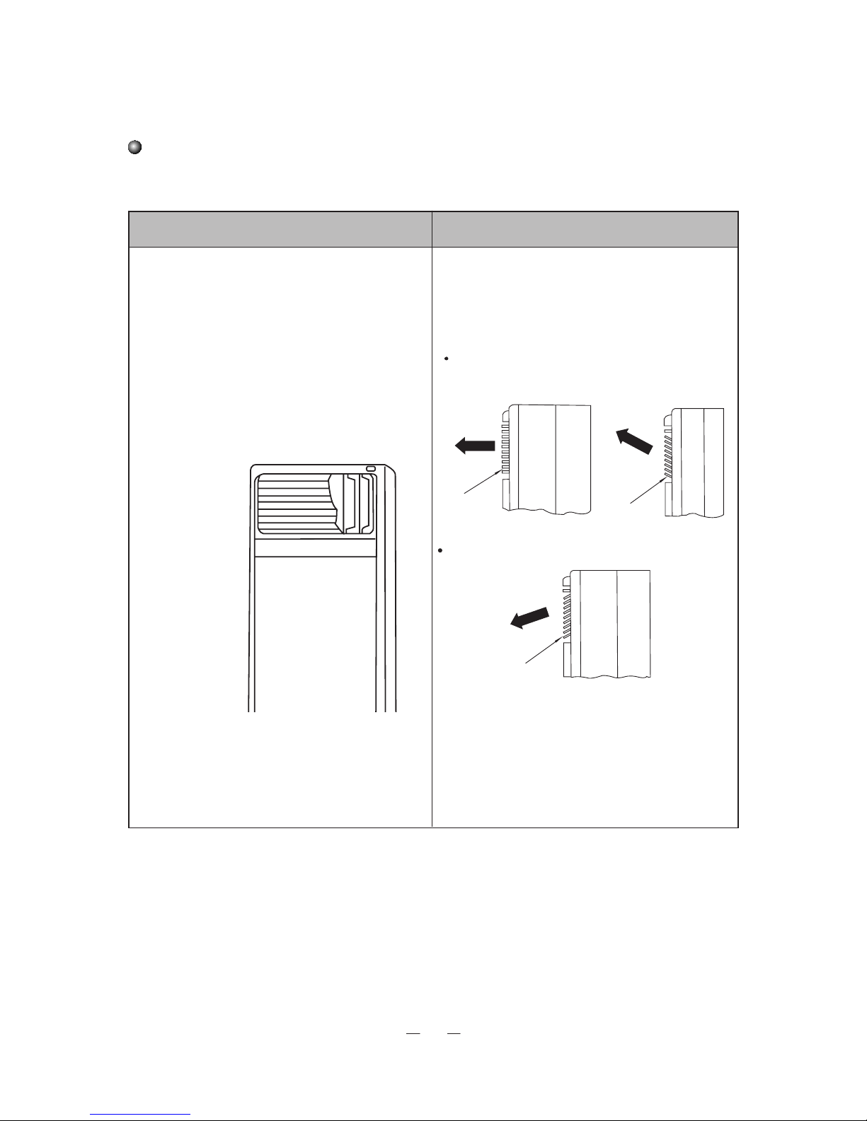
Mentenanta
Reglarea fluxului de aer
* Apasati butonul SWING aflat pe panoul de control
pentru a porni oscilarea stanga/dreapta a fluxlui de
aer. Apasand inca o data butonul SWING, veti opri
oscilarea.
* La fiecare apasare a butonului SWING, mesajul
"SWING" va fi afisat pe ecranul LCD. Daca ventilatorul interior este in functiune, motorul flapsurilor va fi
pornit iar fluxul de aer va fi distribuit stanga/dreapta.
Apasand inca o data butonul, flapsurile vor reveni in
pozitia normala si nu vor mai oscila.
1. Reglarea fluxului de aer STANGA/DREAPTA 1. Reglarea fluxului de aer SUS/JOS
Flapsurile vor fi reglate manual. Tineti flapsurile cu
ambele maini atunci cand reglati directia. In timpul
modului COOL/DRY, reglati flapsurile in sus iar in
modul HEAT, reglati-le pentru ca fluxul de aer sa fie
indretpat in jos.
• Reglarea flapsurilor in modul COOL/DRY
• Reglarea flapsurilor in modul HEAT

17
Curatarea unitatii
στραγγίξτε το
πανί πρίν τον
καθαρισμό
Maner
Capacul grilei de admisie
Curatarea filtrului de aer
Curatati filtrul de aer o data
la 2 saptamani
Demontarea filtrului de aer
Curatarea
Nota
Intretinere
Blocajele pot
cauza defectarea
unitatii.
1. Opriti alimentarea cu energie electrica inainte
de inceperea curatirii
Scoateti din priza numai dupa ce aparatul s-a oprit
complet.
2. Folositi o carpa fina atunci cand curatati
carcasa exterioara.
In cazul in care carcasa este
foarte muradara, inmuiati carpa
in apa calduta (sub 40 de grade
celsius), uscati carpa si apoi
stergeti cu grija.
• Asigurati-va ca aparatul este oprit
• Desurubati capacul grilei de admisie a aerului.
• Scoateti capacul grilei de admisie
• Filtrul de aer este atasat capacului grilei de admisie.
Scoati cu grija filtrul de aer.
• Bateti usor filtrul sau folositi un aspirator electric. In
cazul acumularii murdariei intr-un strat gros, puteti
folosi si apa cu detergent neturu pentru curatare.
Uscati bine inainte reintroducerea filtrului.
• Nu uscati filtrul in lumina directa a soarelui sau in
apropierea unei surse de caldura puternica. Filtrul se
poate deforma.
• Filtrul se poate deforma daca este spalat cu apa
foarte fierbinte (peste 50ºC).
3. Nu folositi acizi sau solutii alkaline pentru
curatenie.
4. Nu udati unitatea cu apa.
* Asigurati-va ca grilele de admisie/evacuare a
aerului nu sunt obturate.

18
Problema Cauze posibile Solutia
Depanare
Daca aparatul dumneavoastra nu functioneaza corect, verificati mai intai situatiile mentionate mai jos, inainte de a cere
ajutorul unui specialist. Dupa verificarea tabelului, in cazul in care aparatul tot nu functioneaza, contactati cel mai
apropiat centru de service.
Aparatul nu porneste 1. Nu este alimentat cu energie electrica.
2. Siguranta este sarita.
3. Tensiune scazuta.
4. Este apasat butonul ON/OFF
5. Defectiune a circuitului.
1. Conectati la reteaua electrica.
2. Contactat centrul de service.
3. Contactati un electrician sau dealer-ul.
4. Apasati butonul ON/OFF
5. Contactati centrul de service.
Aparatul se opreste
imediat dupa pornire, pe
display este afisat
mesajul E1
1. Condensatorul este obturat.
2. Defectiune a circuitului.
3. Functia se opreste cand temperatura
exterioara este de peste 43 grade celsius.
4. Presiune ridicata in tubulatura.
1. Inlaturati elementul care obtureaza.
2. Contactati centrul de service.
3. Montati unitatea exterioara intr-un loc cu
umbra.
4. Contactati centrul de service.
Aparatul se opreste
imediat dupa pornire, pe
display este afisat
mesajul E2
1. Ventilatorul interior nu functioneaza sau
gura de evacuare a aerului este blocata.
2. Temperatura interioara este sub 18 grade
celsius.
3. Senzorul de temperatura este defect.
4. Senzorul de temperatura nu este in pozitie
corecta.
5. Defectiune a circuitului
6. Capacitorul are o scurgere de electricitate.
1. Contactati centrul de service.
2. Verificati daca este neaparata nevoie sa
porniti aparatul de aer conditionat.
3. Contactati centrul de service
4. Montati corect senzorul de temperatura.
5. Contactati centrul de service.
6. Contactati centrul de service.
Temperatura afisata este
0 grade celsius si modul
COOL nu functioneaza
Aparatul se opreste imediat dupa pornire,
pe display este afisat mesajul E4
1. Reconectati cablul senzorului de
temperatura.
2. Montati senzorul de temperatura.
3. Contactati centrul de service.
Eficienta scazuta la
racire.
1. Filtrul de aer este murdar sau infundat.
2. In incapere se afla prea multe persoane
sau surse de caldura.
3. Usa sau fereastra sunt deschise.
4. Gurile de admisie/evacuare a aerului
sunt blocate.
5. Temperatura setata este prea ridicata.
6. Scurgere de refrigerant.
7. Senzorul de temperatura are o eficienta
scazuta.
1. Curatati filtrul de aer.
2. Eliminati sursele de caldura.
3. Inchideti usa sau fereastra.
4. Eliminati blocajele.
5. Setati o temperatura mai joasa.
6. Contactati centrul de service.
7. Verificati senzorul de temperatura.
Eficienta scazuta la
incalzire.
1. Filtrul de aer este murdar sau infundat.
2. Usa sau fereastra sunt deschise.
3. Temperatura setata este prea joasa.
4. Scurgere de refrigerant.
5. Temperatura exterioara este sub -5
grade celsius
6. Defectiune a sistemului.
1. Curatati filtrul de aer.
2. Inchideti usa sau fereastra.
3. Alegeti un nivel mai ridicat al temperaturii.
4. Contactati centrul de service
5. Performanta incalzirii este scazuta.
6. Contactati centrul de service
Eficienta scazuta la
incalzire.
1. Scurgere de refrigerant.
2. Defectiune a sistemului.
1. Contactati centrul de service
2. Contactati centrul de service
Aparatul se opreste
imediat dupa pornire, pe
display este afisat
mesajul E4
1. Scurgere de refrigerant.
2. Defectiune a sistemului.
3. Senzorul de temperatura este defect.
4. Tensiunea este scazuta.
1. Contactati centrul de service
2. Contactati centrul de service
3. Contactati centrul de service
4. Contactati centrul de service

19
Exemplu de cablaj
Model
Sursa de curent
Capacitate de intrare Comutator
Liniile
Sectiunea cablului
de alimentare (mm2)
Sectiunea minima a cablului de
conectare intre unitatea interioara
si cea exterioara (mm
2
).
25A
2.5/1.5
/
380
RFI-66B/RFO-66B
-415V3N~50Hz
Valabil pentru unitatile cu pompa de incalzire (3 faze)
Impamantati corect. In caz contrar, rezistenta unitatii va fi afectata.
Alimentare
Comutatorul principal
Poate fi achizitionat local.
Alimentarea cu
energie electrica a
unitatilor interioare
Alimentarea cu
energie electrica a
unitatilor exterioare.
Unitatea interioara
Impamantare
Impamantare
Cablul de semnal
Unitatea exterioara
Instalarea
Cablajul
• Citit cu atentie manualul inainte de a incepe instalarea.
• Urmariti cu strictete instructiunile atunci cand instalati unitatea interioara si
tubulatura.
• Instalati prima data cablajul unitatii exterioare si apoi cel al unitatii interioare.
Dupa terminarea lucrarilor de cablare si a tubulaturii, conectati unitatea la
alimentarea cu energie electrica.
• Aspectul unitatii se poate schimba fara o notificare prealabila.
NOTA:
1. Luati in considerare mediul de lucru (temperatura, lumina soarelui, ploaie, etc.).
2. Atunci cand tensiunea scade, folositi cabluri conductoare mai groase.
3. Atat unitatea interioara cat si cea exterioara trebuie impamantate.
4. Datele inscrise in acest tabel au doar scop informativ.Respectati normele si regulamentele locale.
• Folositi un circtuit electric separat pentru alimentarea cu energie electrica.
• Circuitul va fi instalat doar de catre o persoana calificata.
• Cablajul se va face conform diagramei. Suruburile trebuie stranse corespunzator.
• Cablurile de alimentare si de conectare trebuie aranjate in asa fel incat acestea sa nu se atinga.
• Conectati faza corect. Aparatul se va opri daca faza nu este corect conectata.

20
Unitate interioara
Conducta maleabila
19 1
Conector forjat
12 1
Unitate
exterioara
Banda izolanta
Protectie izolatoare
Slabirea conductei
Strangerea conductei
Indoiti conducta folosind degetul mare
Raza minima: 100mm
Note cu privire la tubulatura
Conductele de scurgere si refrigerant trebuie sa fie izolate pentru a evita inghetarea lor.
Atat unitatea interioara cat si cea exterioara sunt dotate cu elemente forjate de conectare.
Conducta pentru refrigerant este folosita pentru a conecta unitatea exterioara de cea interioara.
NOTA : Nu indoiti/indreptati conducta maleabila de mai mult de 3 ori.
1. Conectarea conductei.
Asigurati-va ca valva unitatii exterioare este inchisa. De fiecare data cand conectati, scoateti capacul valvei si conectati
conducta cu element forjat imediat (in cel mult 5 minute). In caz contrar pot aparea acumulari de praf, umezeala sau
alte particule care pot intra in conducta si pot cauza defectiun.
Informatii despre conducta maleabila.
• Conducta maleabila trebuie folosita in interior.
• Unghiul de indoire nu trebuie sa fie mai mare de 90 de grade.
• Conducta va fi indoita la mijloc, astfel incat raza va fi mai mare si mai sigura.
• Nu indoiti conducta de mai mult de 3 ori.
Cand indoiti conducta.
• Taiati o parte din izolatie in locul indoirii (folositi banda de pvc dupa indoire).
• Raza/unghiul de indoire trebuie sa fie cat mai mare, astfel conducta nu se va aplatiza si nu se va rupe.
2. Cand folositi conducta de cupru cuparata local, verificati ca valva unitatii exterioare sa fie inchisa. Dupa conectarea
conductei de refrigerant la ambele unitati, vidati conducta folosind valva de control. Dupa evacuarea aerului, inchideti
valva de control si strangeti suruburile.
3. Dupa terminarea pasilor 1 si 2, asigurati-va ca valva unitatii exterioare este deschisa si ca nu exista un blocaj intre
unitati (interioara si exterioara).
Nota: Inainte de fixarea piulitei, aplicati putin ulei de refrigerant la jonctiune.
Nota: Izolati toate componentele expuse ale conexiunii vorjate.

21
>30cm
>4cm
>5cm
>10cm
(Traseul conductei:30cm min.)
Μπροστά
>200cm
>10cm
(Traseul conductei:
30cm min.)
Lant
Surub
Maner
Conducta de scurgere
19 1
Conducta
refrigerant
12 1
Conexiune forjata Conexiune forjata
Conducta de scurgere a unitatii interioare.
Conducta de scurgere conectoare
Conducta scurgere
Banda izolanta
Instalarea unitatii interioare
1. Alegerea locului 2. Instalarea tubulaturii
• Asigurati-va ca unitatea nu va fi afectata de aerul din exterior.
• Asigurati-va ca fluxul de aer admis/evacuat de unitate nu va fi obturat.
• Asigurati-va ca traseul frigorific poate fi tras usor la exterior.
• Asigurati-va ca fluxul de aer va acoperii intreaga incapere
• Asigurati-va ca, in incapere, nivelul umiditatii nu este foarte ridicat si
ca unitatea interioara nu va fi stropita cu uleiuri sau alte substante.
• Asigurati-va ca nu exista pericol de scurgeri si acumulari de gaze.
• Suprafata pe care va fi asezata unitatea interioara trebuie sa fie
dreapta si suficient de solida.
• Asigurati spatiul necesar pentru instalare si mentenanta.
3. Instalarea conductei de scurgere
• Asigurati-va ca traseul conductei de scurgere conduce catre exterior.
• Conectati conducta de scurgere si aplicati banda izolanta.
• In cazul in care conducta de scurgere trebuie trasa la interior, infasurati-o in material izolant (grosime minim 9mm) si
apoi aplicati banda izolanta pentru a evita patrunderea aerului in conducta.
• Dupa conectare, verificati daca apa este evacuata corect si daca exista scurgeri.
• Inlaturati grila de admisie.
• Inainte de instalarea cablajului si a
tubulaturii, scoateti capacul grile de
admisie.
• Desurubati capacul grilei.
• Deschideti capacul grilei tragand usor de
maner.
• Inlaturati lantul si scoateti capacul.

22
Cabluri de semnal Placa terminala a unitatii interioare
Sursa de curent
Sursa de curent
Placa terminala a unitatii exterioare
Mufa de cablaj
L1 L2
L3 N
L1 L2
L3 N
Capacitatea comutatorului
Model
RFI-66B/RFO-66B
25A
Surub
Capacul cutiei
Cablajul unitatii interioare
• Inlaturati capacul cutiti electrice pentru a avea acces la aceasta.
• Efectuati cablajul conform schiteti de mai jos si strangeti firele cu o clema.
Pentru modele cu pompa de caldura (5 faze)

23
Diametru
(mm)
Forta de stranger
(N m)
12 45-50
19 70-75
Cantitatea de
refrigerant incarcata
Folosind
refrigerantul
unitatii
exterioare
Folosind
o pompa
de vacuum
(vid).
Valoarea inscrisa
pe placuta
de identificare
Valoarea de pe placuta
+ 30g/m (incarcati
suplimentar cu 30g
pentru fiecare metro
de conducta adaugat).
Evacuarea
Lungimea
conductei
5m
5-15m
unitate exterioara
conducta pentru gaz
Unitate interioara
supapa de verificare
punct de
conexiune conducte
A
B
C
D
12mm
19mm
-76cmHg
Supapa
Multimetru
Maner supapa
joasa presiune
Multimetru
furtun de incarcare
supapa de
joasa presiune
pompa de
vacuum (vid)
maner supapa
inalta presiune
La deschiderea valvei pentru verificare,
luati in considerare urmatoarele:
Deschideti valva pana la maximul admis.
Nu incercati sa fortati maneta peste limita.
Strangeti capacul cu o cheie.
Instalarea unitatii exterioare
1. Alegerea locului
Nota:
Unitatea exterioara trebuie instalata
pe o fundatie solida pentru a reduce
zgomotul si vibratiile.
Gurile de admisie/evacuare a aerului
nu trebuie obturate.
In zonele de coasta, inaltime ridicata
sau cu vanturi puternice, instalati
unitatea langa perete si folositi un
paravant.
Instalati unitatea intr-un loc bine
ventilat.
Gaura din perete va avea urmatoarele dimensiuni 572x327mm
2. Conectarea conductei de
refrigerant
øStrangerea articulatiilor
• Potriviti tevile, strangeti piulita cu
mana si dupa aceea cu o cheie
(conform figurii de mai jos).
• Nu strangeti foarte tare piulita
pentru a nu o deteriora.
ø La folosirea pompei de vid
*1. Conectati furtunul de incarcare al
valvei la capatul de incarcare a valvei
de joasa presiune (atat supapa de
presiune scazuta cat si cea de
presiune crescuta vor fi stranse
corect).
*2. Conectati furtunul la pompa de vid
*3. Deschideti supapa de joasa
presiune complet
* 4. Porniti pompa de vacuum. La
incepere, desfaceti usor piulita
supapei de joasa presiune pentru a
verifica daca aerul circul. (supapa
pompei de vacuum va schimba
valoarea afisata de la negativ la 0
(zero). Dupa verificare, strangeti
piulita.
* 5. Dupa terminare, inchideti supapa
de joasa presiune pentru a opri
pompa de vacuum. Procesul trebuie
mentinut pentru cel putin 15 minute.
Asigurati-va ca multimetru va afisa
valoarea -1.0x10⁵pa (-76cmHG).
*1. Consultati sectiunea cu privire la
operarea pompei de vacuum la un
rezervor de refrigerant.
*2. Incarcati aparatul cu refrigerant
urmand instructiunile prezentate mai sus.
In cazul in care veti muta unitatea in alta
locatie, eliminati refrigerantul folosind o
pompa de vacuum si un recipient pentru
refrigerant.
■ La folosirea refrigerantului la o unitate
exterioara:
*1. Strangeti puternic piulitele A, B, C,D
*2. Scoateti capacul supapei A
*3. Deschideti supapa pentru lichid B
folosind o cheie hexagonala, in acelasi
timp tinand stransa supapa A cu o
surubelnita, pentru a putea evacua
gazele.
After 15 seconds of exhausting and
refrigerant appears, close one way valve
and tighten bonnet.
Dupa 15 secunde de evacuare, atunci
cand refrigerantul isi face aparitia,
strangeti supapa si capacul.
*4. Deschideti complet supapele de gaz
si lichid, strangeti capacele si verificati de
scurgeri instalatia (puteti folosi apa cu
sapun sau un detector de scurgeri).
*6. Dreschideti complet supapele de
inalta/joasa presiune
*7. Deconectati furtunul de incarcare de
la supapa de joasa presiune.
*8. Strangeti capacul supapei de joasa
presiune
ø1. Evacuarea (folosind o cheie fixa
hexagonala)
furtun de incarcare
Joint nut
Limit block
Bonnet
one-way valve
Valve stem

24
3. Cablajul
3~220V 60Hz
Cablurile exterioare pentru semnal
Cabluri semnal
Cabluri de semnal
Cablu de conectare
pentru alimentare
Cablul de alimentare
Orificiul exterior pentru cabluri
Capac spate
Capac frontal
Placa de baza
Testarea
Dupa ce ati verificat
sistemul impotriva
scurgerilor, puteti porni
testarea
Modul racire
• Alegeti modul COOL
Verificati manualul pentru mai multe
informatii
Sistemul de protectie de 3 minute.
In cazul opririi unitatii, aceasta poate fi
repornita dupa 3 minute.
• Scoateti capacul frontal
• Deschideti cutia pentru cabluri si fixati inelul.
• Trageti cablul conector de la placa de baza a unitatii exterioare si conectati-l la placa de baza a unitatii interioare.
• Conectacti restul cablurilor conform schitei de mai jos si fixati-le cu o clema.

25
Scoateti surubul
Spatiu cablu de protectie
Capatul care va fi ancorat in perete
Capatul care va fi
ancorat in perete
Perete
Unitate interioara
Img 1
Img 2
Instalarea cablului de protectie impotriva inclinarii
Nota:
Pentru a evita inclinarea accidentala a unitatii, va recomandam instalarea
cablului de protectie.
Pasi de urmat:
1. Scoateti surubul capacului superior al unitatii interioare. (Imaginea 1)
2. Scoateti cablul de protectie, puneti-l in locul special din unitatea interioara si
strangeti bine cu suruburi. (Imaginea 2)
3. Fixati celalalt cap al cablului in perete, folosind suruburi (ST4.2X38)
• Schita de mai sus are doar scop informativ. Unitatea dvs. interioara poate fi
diferita.

Activati-va garantia...
in
5
Pasi
simpli!
Pentru inregistrarea
electronicaa garantiei, va rugam sa
accesati link-ul de mai jos :
https://www.inventoraerconditionat.ro/certificatul-de-garantie-inventor-aer-conditionat-si-electrocasnice
Scanati codul QR pentru
a obtine formularul de garantie.
Alegeti tipul de produs pentru
care vreti sa activati garantia
(aparat de aer conditionat, alt
aparat electrocasnic).
Alegeti tipul de garantie
corespunzator produsului
achizitionat.
Completati formularul cu
informatiile cerute (numele
proprietarului, magazinul,
produsul) si apasati SEND.
Veti primi care va confirma
activarea garantiei.
Accesati link-ul de mai jos:
https://www.inventoraerconditionat.ro/
certificatul-de-garantie-inventoraer-conditionat-si-electrocasnice

Scan here to download the latest version of this manual.
Σαρώστε εδώ για να κατεβάσετε την τελευταία έκδοση του εγχειριδίου.
AIR CONDITIONING SYSTEMS
FLOOR STANDING
 Loading...