

• USER’S MANUAL
• ΕΓΧΕΙΡΙΔΙΟ ΧΡΗΣΗΣ
• MANUAL DE UTILIZARE
ENGLISH | ΕΛΛΗΝΙΚΑ
AIR CONDITIONING SYSTEMS
MODELS:
R2FI-50/R2FO-50
FLOOR STANDING
Contents
Notices for Use
.................................................................4
Names of Each Part of the Unit
............................................6
Operation of Remote Controller
...........................................12
Use and Maintenance
Clean and Care
...............................................................20
Troubleshooting ...............................................................22
Installation Dimension Diagram ...........................................28
Installation of Indoor Unit
....................................................30
Installation of Outdoor Unit .................................................34
Test Operation and Check after Installation ............................36
Installation Service
Cautions for Operation ........................................................1
Notes for Installation .........................................................25
Adjustment of Swing .........................................................17
Instruction to Special Functions ...........................................19
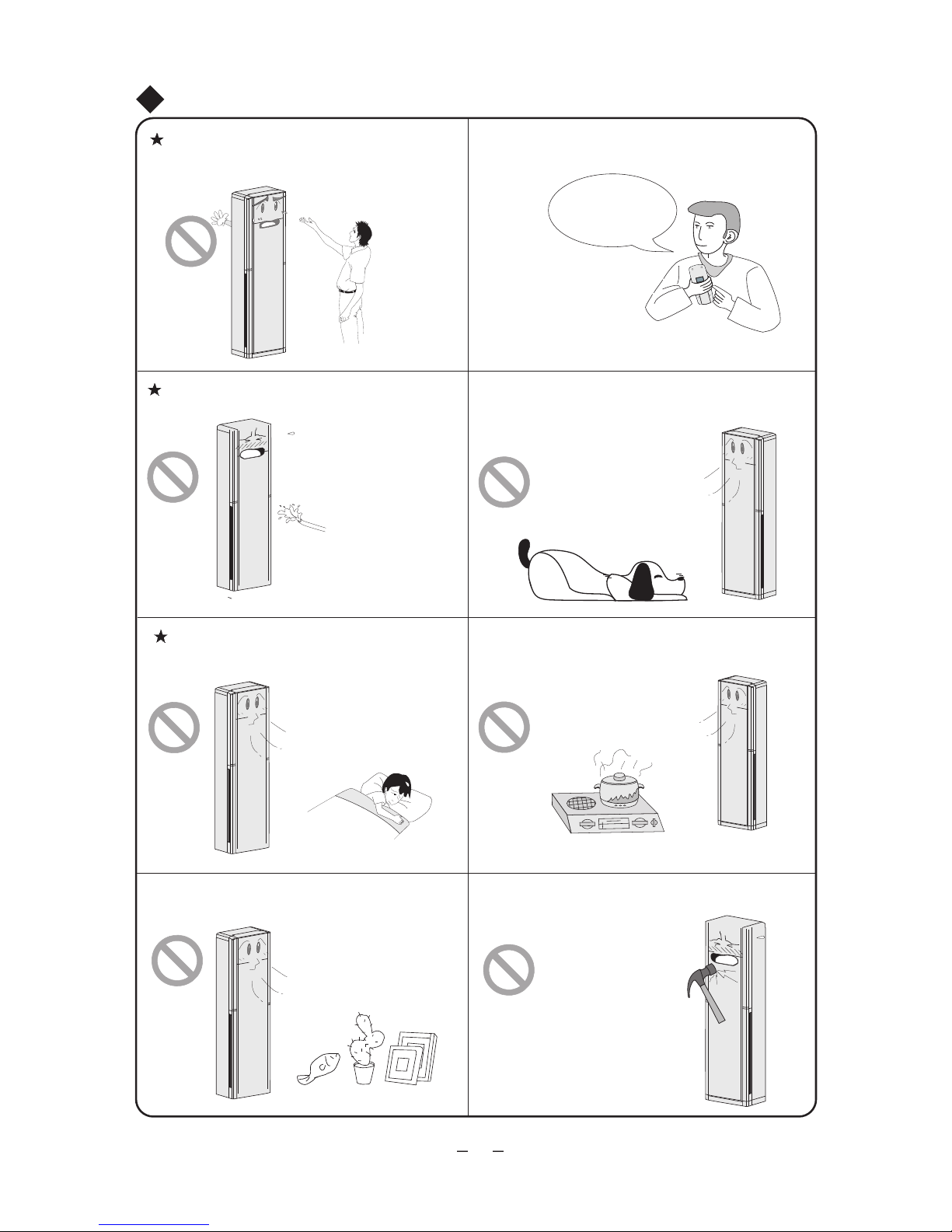
The symbol stands for the items
which should be forbidden
The pictures about the unit in this Instruction may be different from the actual
ones.Please be subject to the actual one.
The symbol stands for the items
which should be followed
Name and Function of Each Button of Air Conditioner................8
Do not dispose this product as unsorted municipal waste.
Collection of such waste separately for special treatment
is necessary.
This appliance is not intended for use by persons (including children) with
reduced physical, sensory or mental capabilities, or lack of experience and
knowledge, unless they have been given supervision or instruction concerning
use of the appliance by a person responsible for their safety. Children should
be supervised to ensure that they do not play with the appliance.
★
★
★
Please read the following carefully before operating.
WARNING
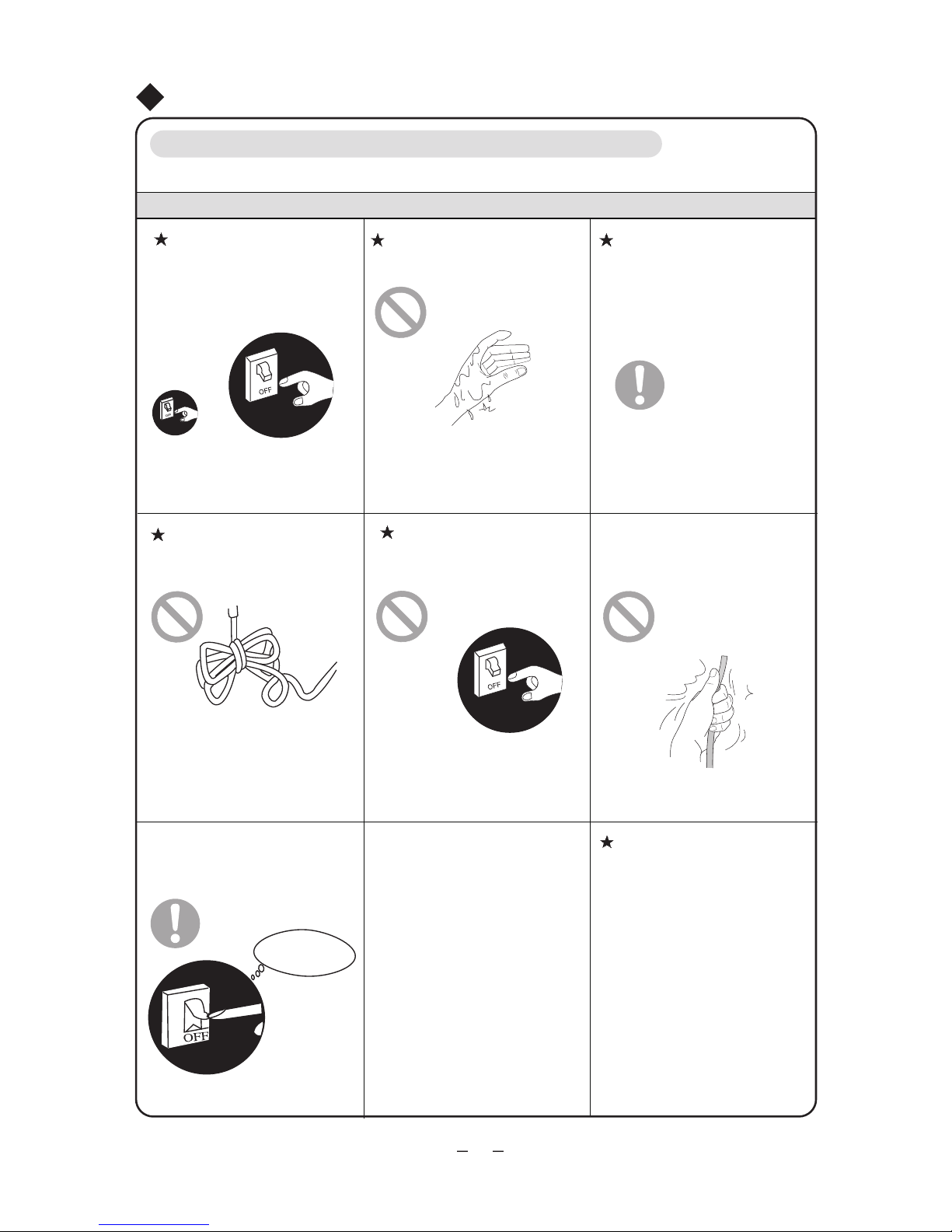
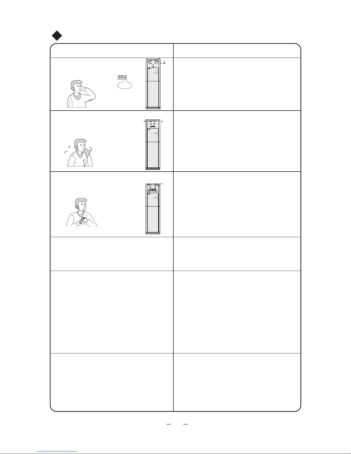
Once abnormality like burning
smell occurs,please cut off the power
supply immediately and then contact
may be damaged and electric shock
with service center .
If the abnormality still exists, the unit
or fire may result.
Don't operate the air conditioner
with wet hand.
Never cut off or damage power
cord and signal wire. If they are
damaged,replace them with special
cord by professionals.
Special circuit must be adopted
for power supply to prevent fire.
Be sure to pull out the power
plug when the air conditioner is not
in use for a long time.
Otherwise, the accumulated dust
may cause overheating or fire.
Never damage the electric wire
or use the one which is not specified.
Otherwise, it may cause overheating
or fire.
During cleaning, please cut off
the power supply.
Cut off power supply
Otherwise, it may cause electric
shock or damage.
The power supply must adopt
special circuit with protection of air
switch and enough capacity.Do not
turn on or off the unit frequently to
Cautions for Operation
protect the air conditioner.
The power supply and voltage
should keep stable. Electric compon-
Do not use octopus multipurpose
plug
or mobile terminal board for
wire connection.
ents are easy to be damaged for high
voltage. Refrigeration system will be
damaged and compressor and electric
components won't operate if voltage
is too low.
1
Otherwise, it may cause electric shock.
2
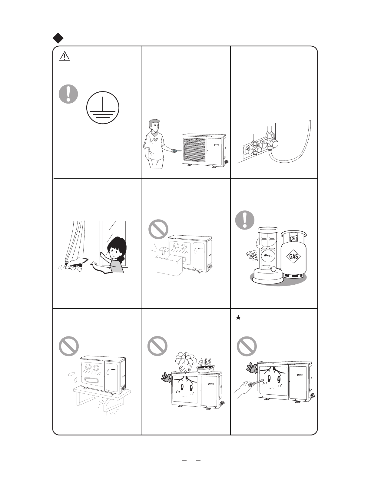
Don't make windows and doors open
ria ehtfo noitarepo gnirud emit gnol a rof
conditioner.
Keep pressurized spray,gas holder
and so on away from the indoor unit
It may cause fire or explosion.
Don't step on the top of the outdoor
unit or place anything on it.
There is the danger of fall of things or
Please note whether the installation
stand is firm enough or not.
If damaged, it may cause fall of the unit
and injury of people.
Don't attempt to repair the air condi-
tioner by yourself.
Improper repair may cause electric shock
or fire, so you should contact the service
center to repair.
Never insert any foreign matter into
the air conditioner to avoid damage of
the air conditioner. And never insert
your hands into the air outlets of indoor
and outdoor units.
The operation of cut-off valve of
outdoor unit must be performed by
professional personnel in order to
Never block the air inlet and outlet
of the indoor and outdoor units.
★
★
★
★
★
★
★
★
avoid damage to compressor for
leakage of the system.
Earthing:the unit must be
earthed reliably! The earthing
wire should connect with special device
of buildings.
professional does not recognize.
It may reduce efficiency of the unit.
It may reduce efficiency
or cause stop of
the unit and even fire.
above 1m .
people .
If not, please ask the qualified personnel
to install. Furthermore, don't connect each
wire to gas pipe, water pipe, drainage
pipe or any other improper places which
Cautions for Operation
Keepproper temp
difference between
room and outdoors
★
★
★
★
★
Don't insert your hands or stick into the air inlet or outlet.
Select the most appropriate temperature.
Splashing water on the air conditioner may cause electric
shock and malfunction.
Don't apply the cold wind to the body for a long time or
Don't use the air conditioner for other purposes, such as
drying clothes, preserving foods, etc.
Don't place a space heater near the air conditioner.
Or CO toxicosis may occur for imcomplete burning.
Don't blow the wind to animals and plants directly.
It may cause a bad influence to them.
Don't strike the glass door with heavy things to avoid damage.
set too low temperature.
Cautions for Operation
3
Working Principle and Special Functions for Cooling
Principle:
Anti-freezing Function:
If the unit is running under cooling mode at low temperature, the surface of indoor heat
below, the indoor microcomputer will make the compressor stop to protect the unit.
will decrease with the increase of outdoor temperature.
so that indoor ambient temperature will be decreased.By this principle, its cooling capacity
℃
exchanger will frost.When the temperature of indoor heat exchanger decreases to -2 or
Air conditioner absorbs heat from room and then transmit it outdoors for discharge of it,
Working Principle and Special Functions for Heating
*
*
*
*
*
Principle:
Defrosting:
defrosting function will act and heat running will briefly stop for 5-10min.
so that indoor temperature will be increased.
If outdoor temperature gets much lower, please operate with other heating equipments.
Note:By this principle, heating capacity of the unit will decrease with the decrease of outdoor
Air conditioner absorbs heat from outdoors and transmit into the room for distribution,
temperature.
When outdoor temperature is low with high humidity, the outdoor heat exchanger will
frost after the unit runs for a period of time, which affects heating. At this time, auto
malfunction.
During defrosting, the outdoor unit may emit vapor,which is due to rapid defrosting, not
During auto defrosting, both indoor and outdoor fans stop running.
The unit will resume heating after defrosting.
Notices for Use
Under heating mode, if indoor heat exchanger hasn't reached certain temperature under
the following three kinds of states, the indoor fan won't start to avoid blow of cold air (within
90s).
1. At the beginning of heating 2. After auto defrosting 3. Heat at ultra-low temperature
Anti-cold Air Function:
4

★
℃
"HEAT"
running
Outdoor temp above 24
"COOL"
running
"DRY"
running
Outdoor temp below -7
℃
Room temp above 27
℃
Outdoor temp
below 18
Outdoor temp
above 48
℃
℃
Outdoor temp
below 21
℃
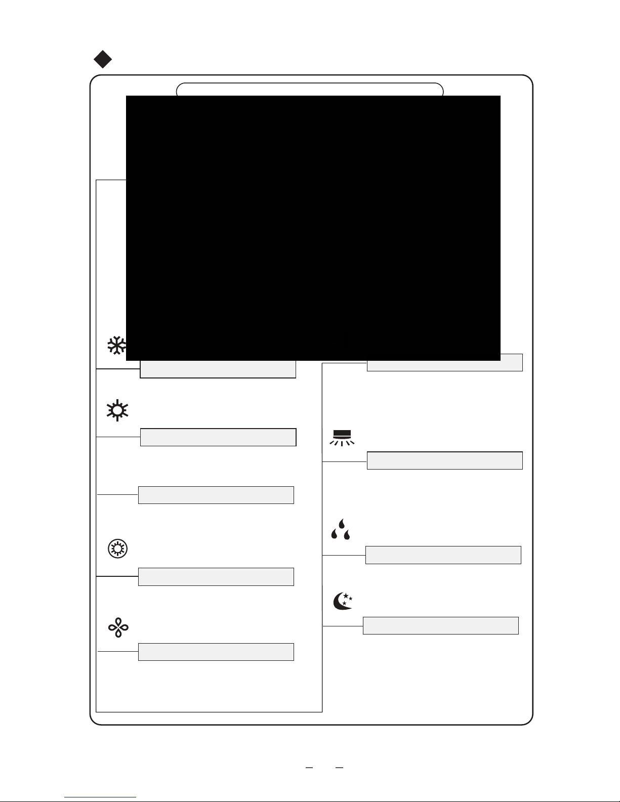
Condition that unit can't normally run
Under relative humidity above 80% (door and windows open), long-time cooling or
dehumidifying, there will be dew dripping off near the air outlet.
Notices for Use
About display of ambient temperature:
1.In order to prolong lifetime of compressor, the air conditioner will automatically control start
or stop of compressor according to actual condition. It will delay for a period of time to stop
although the ambient temperature reaches setting temperature.
2.Because of difference among different regions in the room, the air conditioner will automatically
supplement temperature to improve comfort. It is normal state that the temperature displayed
on the unit is different from that detected by the user.
5
The protection devices may be active or inactive in certain temp range of the following table.
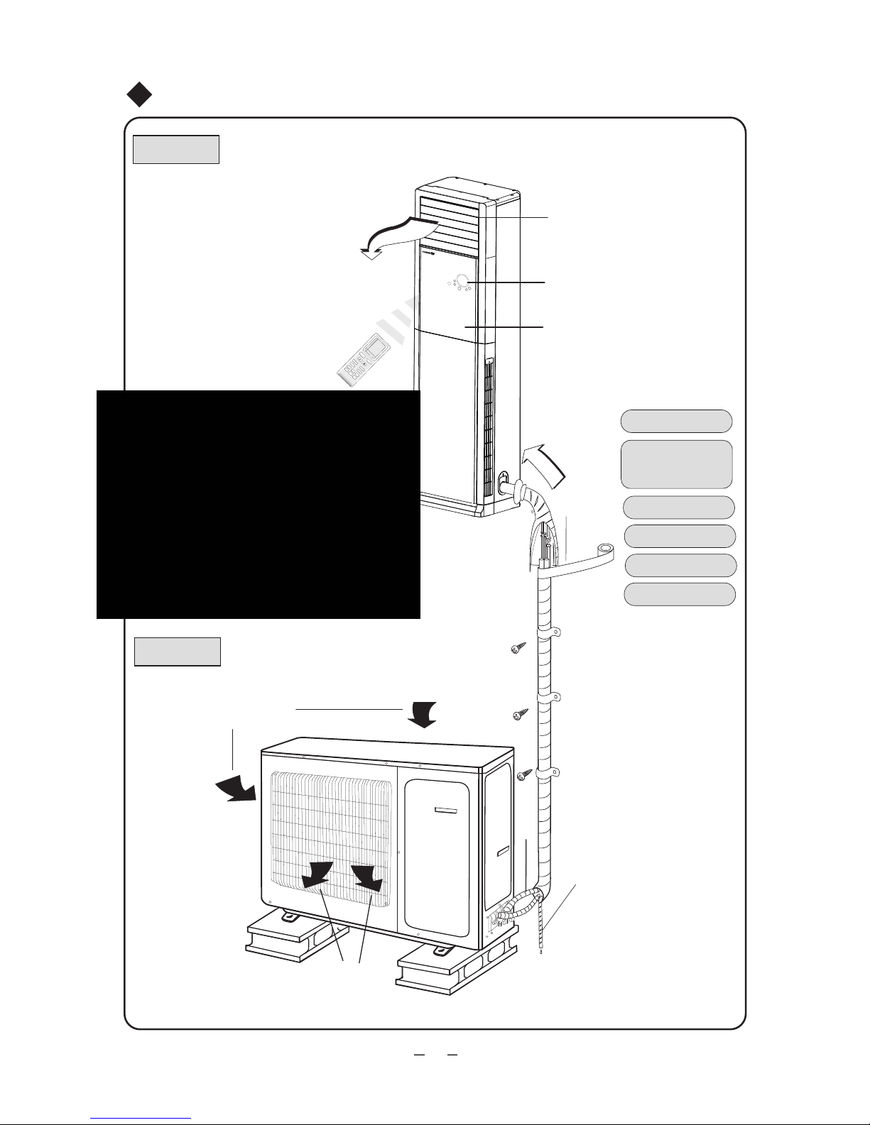
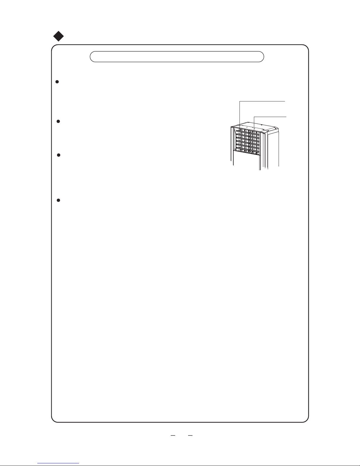
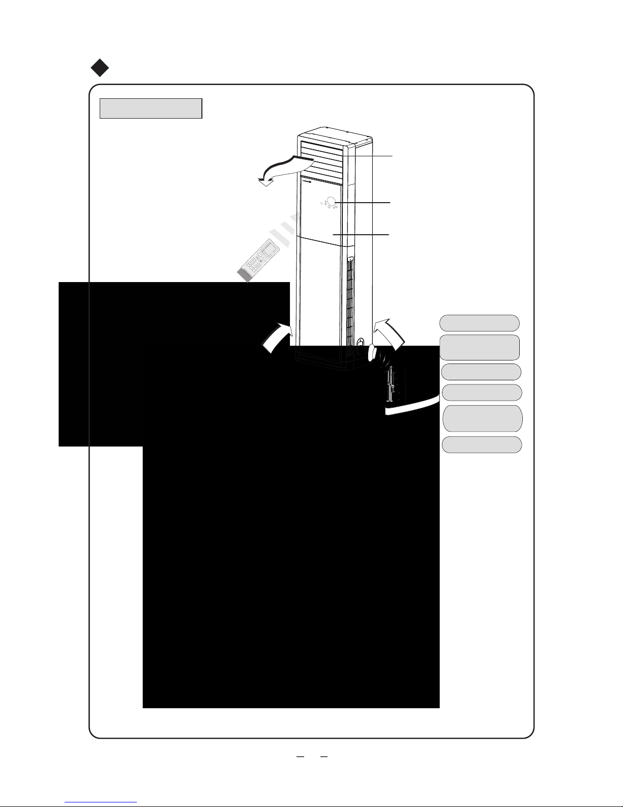
⑹
Indoor unit
Air out
Air in
Outdoor unit
(1) Air outlet
(2) Display screen
and button
(3) Front panel
(4) Connecting pipe
(5) Drainage pipe
(6) Wrapping tape
Names of Each Part of the Unit
⑵
⑴
⑶
⑸
(4)
Air out
Air in
Display screen
.
6
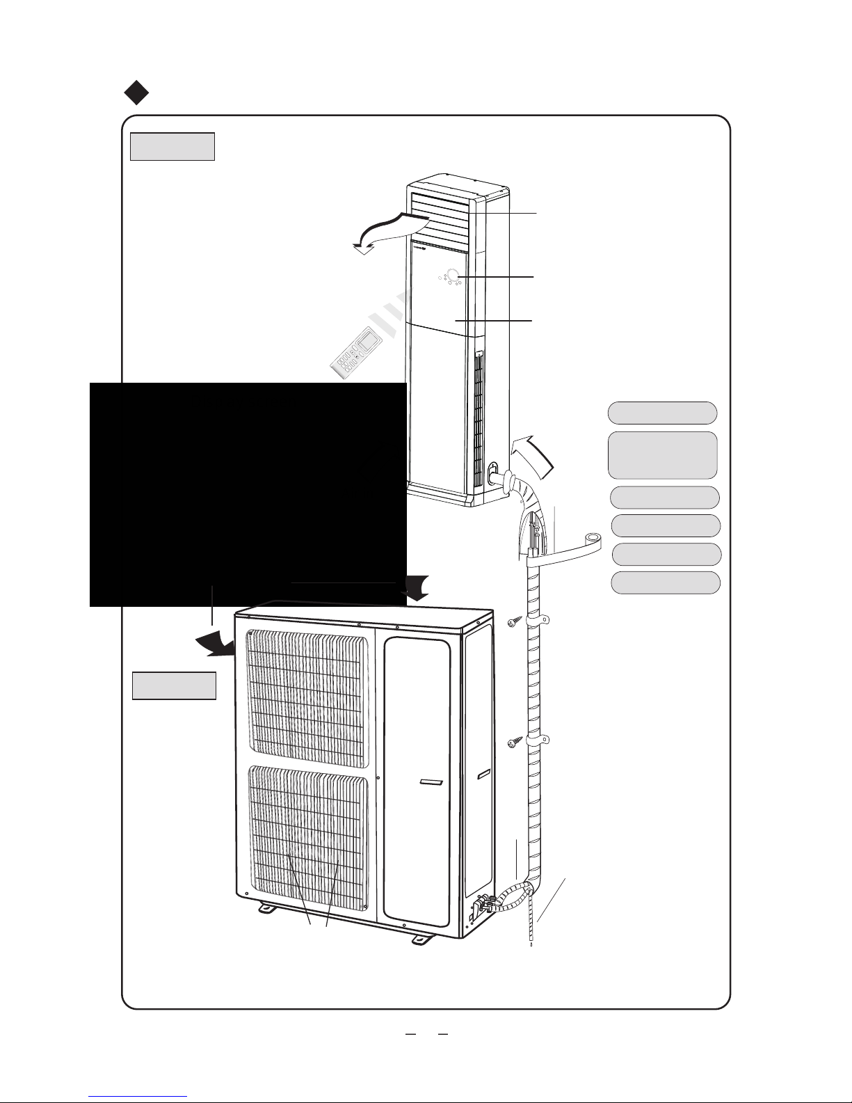
⑹
Indoor unit
Air out
Air in
(1) Air outlet
(2) Display screen
and button
(3) Front panel
(4) Connecting pipe
(5) Drainage pipe
(6) Wrapping tape
Names of Each Part of the Unit
⑵
⑴
⑶
Display screen
(4)
⑸
Outdoor unit
Air in
Air out
7
.
8
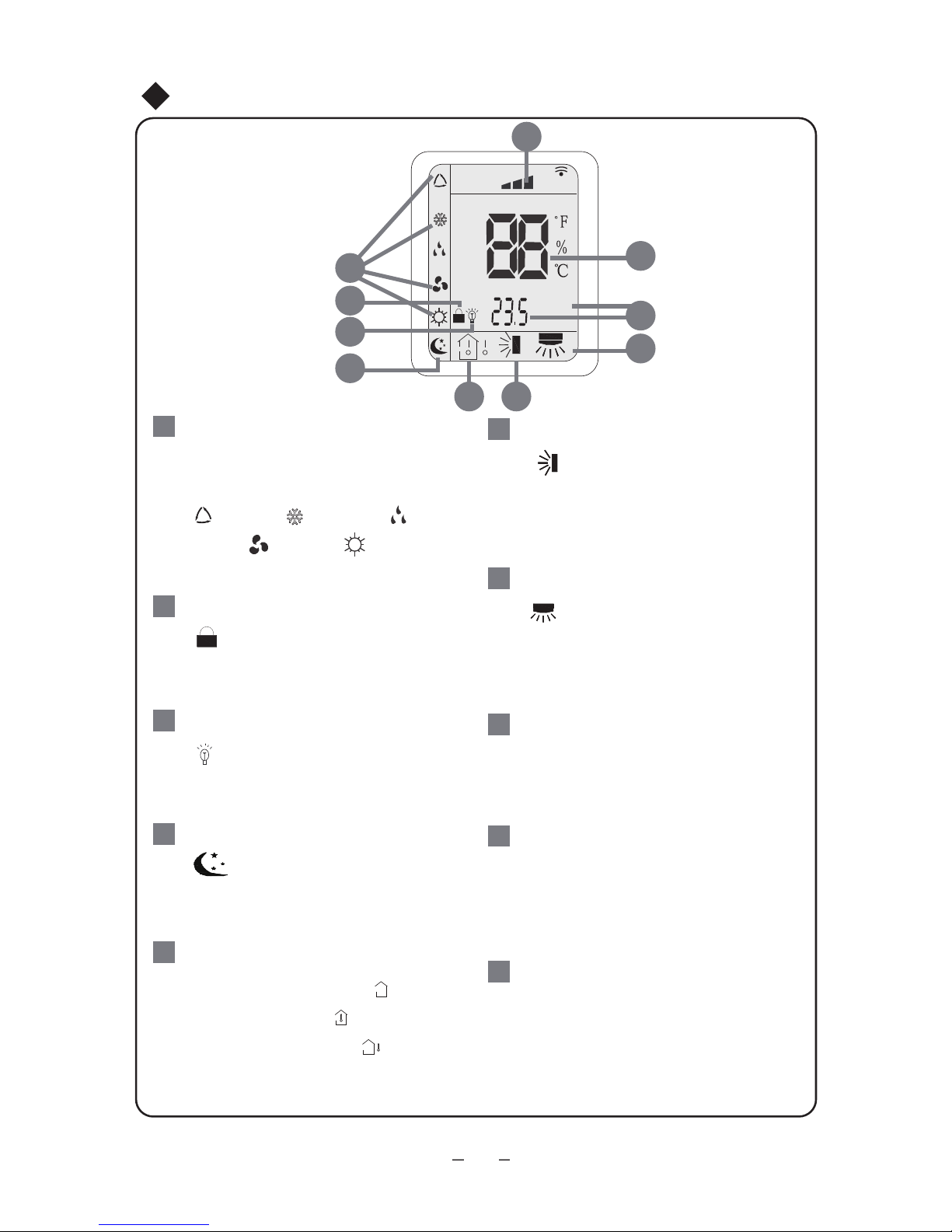
Function Button and Display of Air Conditioner
ON/OFF
●
ON/OFF Button
Press this button to turn on/off the unit.
When turning on/off the unit, the timer
and sleep function which have been set
before will be cleared.
Note: during DRY operation, press
ON/OFF button to turn on the unit directly.
●
Name and Function of Each Button of Air Conditioner
MODE
AUTO COOL
HEAT
DRY
FAN
●
●
●
●
Function Button
FUNCTION
Function Button of Air Conditioner
When the unit operates, it is green;
when the unit is energized but doesn’t
operate, it is red.
Mode Button
Press this button and the mode will
change as follows:
AUTO: in this mode, the operation mode
is automatically determined by controller
based on change of room temperature.
COOL: cooling status is displayed.
DRY: the humidity is decreased but room
temperature doesn’t change.
FAN: in this mode, compressor doesn’t
operate and only indoor fan operates.
HEAT: heating status is displayed.
(Note: there is no HEAT mode for cooling
-only unit).
When the unit is operating, press
function button to set function as per
the sequence of vertical SWING,
horizontal SWING, X-FAN, E-Heater,
TIMER, SLEEP, SET TEMP,
ROOM TEMP. A function which blinks
can be set. Use button “▲”or “▼” for
setting. If there is no change within 5
seconds after setting, the setting will
be confirmed. Or press function button
again to confirm this function.
When the unit is in X-FAN status,
press function button to turn off the
unit directly. If the unit has been turned
off and not in X-Fan status, press
function button to set TIMER ON.
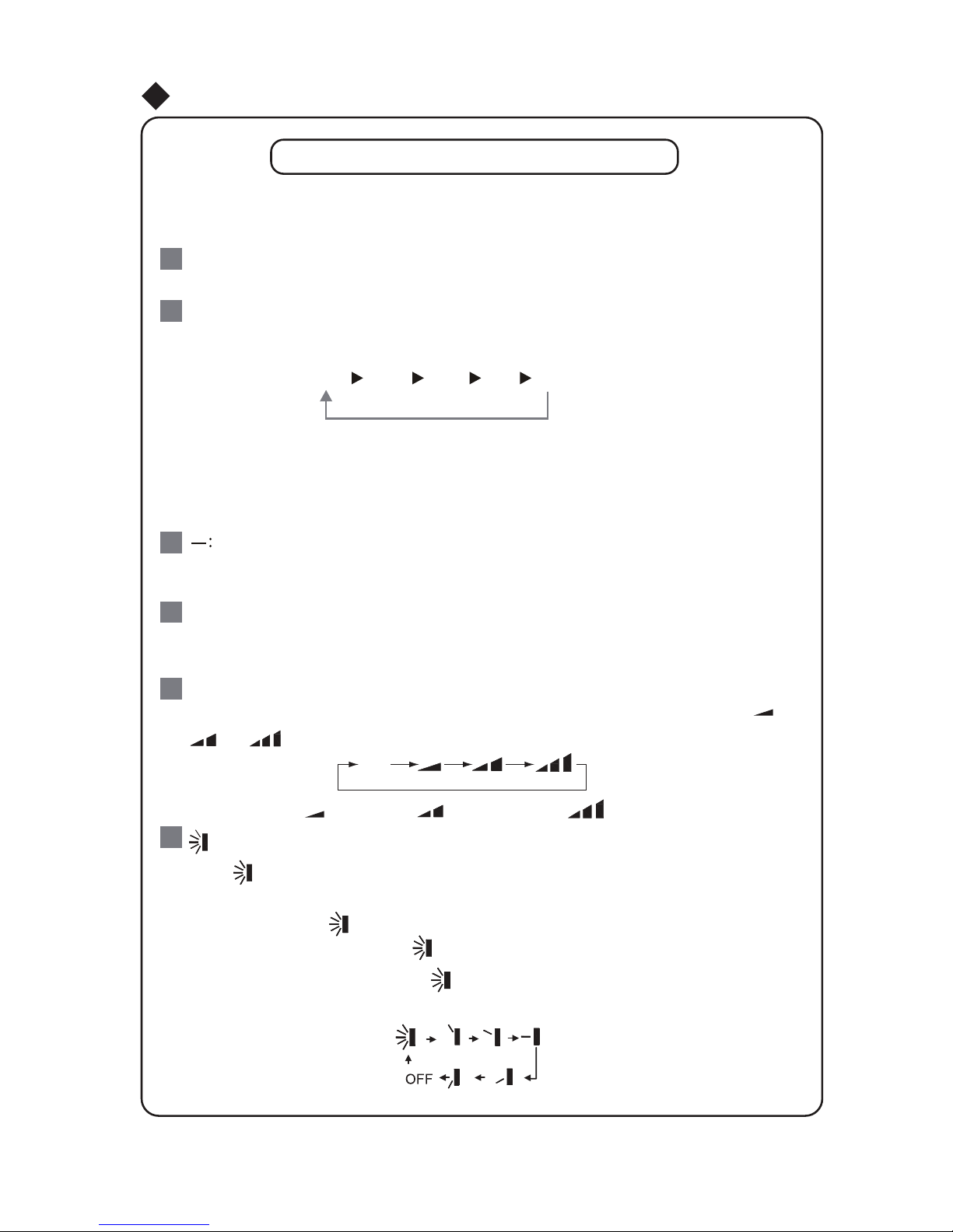
SPEED
SPEED Button
Press this button, fan speed can be
circularly changed as the sequence
of AUTO-LOW-MED-HIGH-AUTO.
●
●
●
●
空调器功能键空调器功能键
Function Button and Display of Air Conditioner
Function Button of Air Conditioner
Name and Function of Each Button of Air Conditioner
▲ and ▼
Buttons ▲ and ▼
When function is not set, each press of
▲ or ▼ will make set temperature
increase or decrease for 1 ℃ and the
adjustment range is 16℃~30℃.
The SET TEMP button is invalid in AUTO
mode.
(Set ▲ and ▼ to circularly chose this
function. When setting function, the
direction can be reversed. )
Press buttons ▲ and ▼ for continuous
3 seconds, all buttons on display panel
will be shielded. If pressing any button
after that, the buzzer will sound and nixie
tube will display LC which will blink for
3 times and then resume normal display
so as to remind user of that buttons have
been locked. When pressing these two
buttons again, the shielding function will
be released and normal display will be
resumed.
▲ and ▼
Buttons ▲ and ▼ (continued )
When the unit is energized for the first
time, if no button pressed:
①press ▲ for continuous twice within
20 seconds, the unit will enter force
heating operation immediately. In that
case, vertical louver will turn to the
minimum angle, all loads will be turned
on, and indoor and outdoor fan will
operate at high speed. If there is no
malfunction of temp sensor, all icons
will be displayed. If malfunction of temp
sensor exists, nixie tube will display
malfunction code and buzzer will sound.
The unit will stop operation in 5 minutes
later or it receives turning off signal
within 5 minutes, then stops operation
and enters normal standby status.
②press ▼ for continuous twice within
20 seconds, the unit will enter force
cooling operation immediately. In that
case, vertical louver will turn to the
minimum angle, all loads except 4-way
valve will be turned on, and indoor and
outdoor fan will operate at high speed.
If there is no malfunction of temp sensor,
all icons will be displayed. If malfunction
of temp sensor exists, nixie tube will
display malfunction code and buzzer
will sound. The unit will stop operation
in 5 minutes later or it receives turning
off signal within 5 minutes, then stops
operation and enters normal standby
status.
① and ②are for testing only.
9

10
AUTO
●
●
In this mode, compressor doesn’t operate
and only indoor fan operates.
●
In this mode, the operation mode will
be determined by controller based on
change of room temperature.
Auto Display
Fan Display
●
●
●
●
●
●
●
●
●
空调器功能键空调器功能键
Function Button and Display of Air Conditioner
Function Button of Air Conditioner
Name and Function of Each Button of Air Conditioner
Room Temperature
Operation Display
When the unit is energized, the display
will be on.
Setting
Set temperature is displayed.
When “Turbo” is bright, turbo function
is set.
Turbo
Room temperature is displayed.
TIMER
Timer Display
Set timer to turn on or turn off the unit.
Timer can only be set by remote control.
FAN
Room Temperature Display/Set
Temperature Display/ Timer Display
Set temperature can be set by function
button or remote control.
Timer can be set by remote control.
Where there is malfunction, only
malfunction code will be displayed.
During normal operation, if temperature
or timer is set by button or remote
signal, the corresponding setting will
be displayed for 5 seconds and then
set temperature will be displayed (set
temperature or room temperature).
During defrosting operation, H1 will be
displayed as default. If set temperature,
timer, temperature display are set by
button or remote control, the display
will follow the following sequence: set
temperature, timer, temperature display.
During defrosting operation(H1), each
status will be displayed for 5 seconds
and then next status will be entered. If
the status (set temperature, timer,
temperature display or defrosting)
doesn’t change, it will not be displayed
and the default or set temperature will
be displayed finally. The room
temperature will be displayed as default
after energization.
11
●
Sleep status is displayed and this
function can only be set by remote
control.
Sleep Display
●
Vertical Swing Display
●
Horizontal Swing Display
●
Reduce humidity and keep room
temperature unchanged.
DRY Display
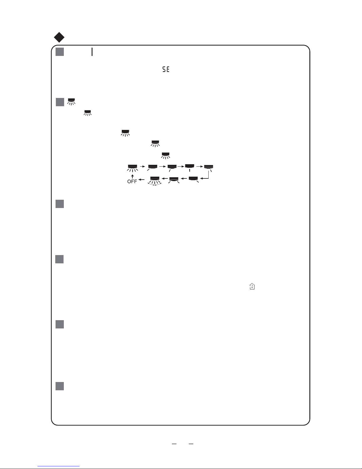
Speed Display
●
The speed can be set by button or remote
control: AUTO, LOW, MED, HIGH, or
TURBO will be displayed accordingly.
E-HEATER Display
●
X-FAN Display
●
●
●
Cooling Operation Display
●
The cooling status is displayed.
Heating Operation Display
●
Heating status is displayed.
When this word is displayed, the function
of E-HEATER is turned on.
When this word is displayed, the function
of X-FAN is turned on.
空调器功能键空调器功能键
Function Button and Display of Air Conditioner
Function Button of Air Conditioner
Name and Function of Each Button of Air Conditioner
COOL
HEAT
SPEED
E-HEATER
X-FAN
SWING
The swing status of horizontal louver is
displayed.
Only two statuses: it is on that means
operation while off means stop of
operation.
The swing status of vertical louver is displayed.
Only two statuses: it is on that means
operation while off means stop of operation.
DRY
SLEEP
SWING
12
FAN
AUTO
OPER
HEALTH
AIR
FILTER
TURBO
ON/OFF
X-FAN
HOUR
HUMIDITY
ON/OFF
MODE
FAN
X-FAN
TURBO
TEMP
TIMER
SLEEP
LIGHT
2
11
7
10
13
9
43
12
8
6
14
5
1
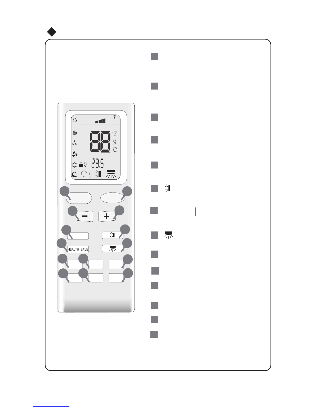
Press it to start or stop
ON/OFF
operation.
MODE
+
-
Press it to select operation mode
(AUTO/COOL/DRY/FAN/HEAT).
: Press it to increase temperature
setting.
: Press it to decrease temperature
setting.
FA
HEALTH SAVE
N
Press it to set up & down swing angle.
Press it to turn on/off the light.
TIMER
X-FAN ( page 15)
( page 15)
TEMP( page 15)
TURBO( page 15)
SLEEP( page 16)
LIGHT
Press it to set fan speed.
Press it to set timer ON/ timer OFF.
1
2
Press it to turn on or off health function.
7
4
3
5
6
Press it to set left & right swing angle.
8
11
9
10
12
13
14
Operation of Remote Controller
Operation of Remote Controller
LOCK icon:
MODE icon:
LIGHT icon:
If MODE button is pressed,
current operation mode icon
Pressing TEMP button,
(set temperature),
ambient temperature)
(outdoor ambient temperature)
and blank is displayed circularly.
(indoor
is displayed by pressing "+"
and “-” buttons simultaneously. Press
them again to clear the display.
is displayed when pressing the
left & right swing
button.Press this
button again to clear the display.
is displayed when pressing
the
up & down swing
button.
Press this button again to clear the
display.
is displayed by pressing the
LIGHT button. Press LIGHT button
again to clear the display.
(AUTO), ( COOL),
(DRY), (FAN) or (HEAT
only for heat pump models) will show.
15
Left & right swing icon:
20
Up & down swing icon:
After pressing TIMER button,
ON or OFF will blink.This area
will show the set time.
SET TIME display:
21
This area will show the set temperature. In SAVE mode,"SE" will be
displayed. During defrosting opera tion, “H1” will be displayed.
DIGITAL display:
23
Press FAN button to select the
desired fan speed setting(AUTO-
Low-Med-High).Your selection will
be displayed in the LCD windows,
except the AUTO fan speed.
FAN SPEED display:
24
16
17
SLEEP icon :
is displayed by pressing
the SLEEP button. Press this
button again to clear the display.
18
TEMP icon:
19
FAN
AUTO
OPER
HEALTH
AIR
FILTER
TURBO
ON/OFF
X-FAN
HOUR
HUMIDITY
191520
18
16
17
21
22
23
24
13
22
19
Remote controller description
ON/OFF
Notice: This is a general use remote controller, it could be used for the air conditioners
with multifunction; For some function, which the model doesn't have, if press the corresponding button on the remote controller that the unit will keep the original running status.
:
MODE :
+ :
FAN:
1
2
4
3
5
Operation of Remote Controller
-14-
Press this button to turn on the unit. Press this button again to turn off the unit.
Each time you press this button,a mode is selected in a sequence that goes from AUTO,
COOL, DRY, FAN,and HEAT
*
,as the following:
AUTO
COOL
DRY
FAN HE
AT
*
*Note: Only for models with heating
function.
After energization, AUTO mode is defaulted. In AUTO mode, the set temperature will not
be displayed on the LCD, and the unit will automatically select the suitable operation
mode in accordance with the room temperature to make indoor room comfortable.
Press this button to decrease set temperature. Hold it down for above 2 seconds to
rapidly decrease set temperature. In AUTO mode, set temperature is not adjustable.
Press this button to increase set temperature. Hold it down for above 2 seconds to
rapidly increase set temperature. In AUTO mode, set temperature is not adjustable.
This button is used for setting fan speed in the sequence that goes from AUTO,
,
to
then back to Auto.
,
,
Auto
Low speed
Medium speed
High speed
:
6
defaults to simple swing condition.
If the unit is turned off during swing operation,the louver will stop at present position.
changes as below:
●
●
●
●
Press button to start or stop up & down swing function.The remote controller
Press + button and button at the same time at unit OFF to switch between
simple swing and static swing; blinks for 2 seconds.
In static swing condition, pressing button, the swing angle of up & down louver
10
TEMP:
Press this button, could select displaying the indoor setting temperature or indoor ambient
temperature.When the indoor unit firstly power on it will display the setting temperature,
if the temperature's displaying status is changed from other status to" ",displays the
ambient temperature, 5s later or within 5s, it receives other remote control signal that will
return to display the setting temperature. if the users haven't set up the temperature
displaying status,that will display the setting temperature.
HEALTH SAVE:
Press HEALTH part of this button to turn on or off HEALTH function.
7
Press TIMER button at unit ON to set TIMER OFF; HOUR OFF blinks. Press TIMER
button at unit OFF to set TIMER ON; HOUR ON blinks. In this case, pressing + or -
button changes time setting. Holding down either button rapidly changes time setting
(time setting range 0.5-24hours). Press TIMER button again to confirm setting; HOUR
O
N/OFF stops blinking. If there is not any
operation of button within 5 seconds during
HOUR ON/OFF blinking, TIMER setting will be cancelled.
TIMER:
11
X-FAN:
TURBO:
9
12
15
:
8
Pressing X-FAN button in COOL or DRY mode,the icon "X-FAN" is displayed and the
indoor fan will continue operation for 10 minutes in order to dry the indoor unit even though
you have turned off the unit.
After energization, X-FAN OFF is defaulted. X-FAN is not available in AUTO, FAN and
HEAT mode.
Press this button to activate / deactivate the Turbo function which enables the unit to
reach the preset temperature in shortest time. In COOL mode, the unit will blow strong
cooling air at super high fan speed. In HEAT mode, the unit will blow strong heating air
at super high fan speed. (This function is not applicable for some models).
Pressing SAVE part of this button, is displayed and the unit goes into SAVE operation
mode. Press SAVE part of the button again to cancel SAVE function. During SAVE
operation, the temperature and fan speed is not adjustable.
Operation of Remote Controller
changes as below:
●
●
●
If the unit is turned off during swing operation,the louver will stop at present position.
●
Press button to start or stop left & right swing function.The remote controller
defaults to simple swing condition.
Press + button and button at the same time at unit OFF to switch between
simple swing and static swing; blinks for 2 seconds.
In static swing condition, pressing button, the swing angle of left & right louver
SLEEP :
LIGHT:
13
14
Press this button to go into the SLEEP operation mode. Press it again to cancel this
function. This function is available in COOL , HEAT (Only for models with heating
function) or DRY mode to maintain the most comfortable temperature for you.
Press LIGHT button to turn on the display's light and press this button again to turn off
the display's light. If the light is turned on , is displayed. If the light is tunrned off,
disappears.
16
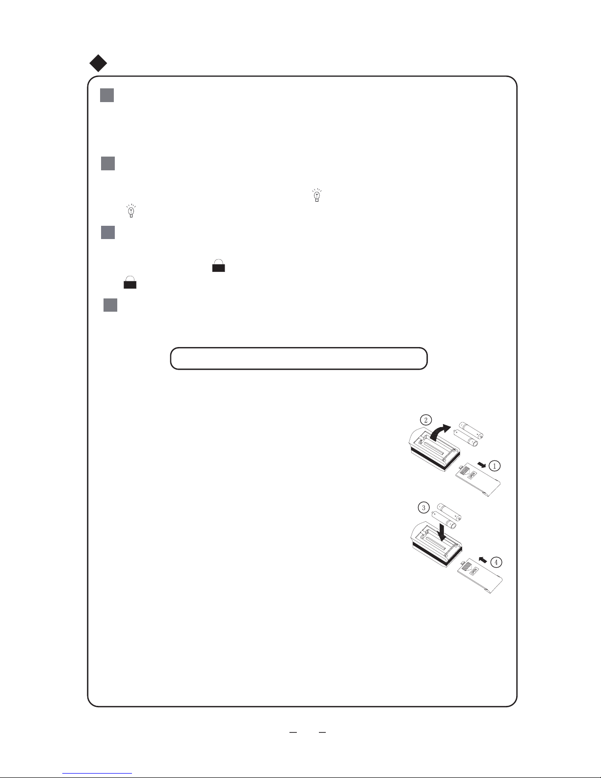
Replacement of Batteries
properly, replace the batteries.
★
●
●
●
●
●
1.Remove the battery cover plate from the rear of the remote controller.
(As shown in the figure)
2.Take out the old batteries.
3.Insert two new AAA1.5V dry batteries, and pay attention to the polarity.
4. Reinstall the battery cover plate.
When replacing the batteries, do not use old or different batteries,
If the wireless remote controller will not be used for a long time, please
otherwise, it may cause malfunction.
remove batteries to prevent damage from leaking batteries.
The operation should be performed in its receiving range.
It should be kept 1m away from the TV set or stereo sound sets.
If the wireless remote controller does not operate normally, please take
the batteries out and reinsert
them after 30 seconds. If it still can't operate
Sketch map for
replacing batteries
Notes:
3
2
Operation of Remote Controller
Combination of "+" and "-" buttons: About lock
15
Combination of "MODE" and "-" buttons:
About switch between Fahrenheit and Centigrade.
16
Press "+" and "-" buttons simultaneously to lock or unlock the keypad. If the remote
controller is locked, is displayed. In this case, pressing any button,
blinks three times.
At unit OFF, press "MODE" and "- " buttons simultaneously to switch between℃and
℉.
Up & Down Swing
Up &down swing can be selected to control start or stop
:setoN
of up & down swing motor by pressing up & down button on
remote controller or FUNC button on displayer,so that guide
louver will swing up and down or stop at a certain angle.
If indoor fan has operated,press up &down button on remote
controller. Refer to remote controller instruction for swing
mode.
Select up & down swing button on displayer to set it,and
then press button to start or stop swing.
Press
▼or ▲
it once to start and repress it to stop.
If stop of swing is selected,the characters and icon about
up & down swing will disappear. When other states are selected
,
characters and icon about up & down swing will show again.
Front or upward air supply should be set for cooling and
dehumidifying mode.(Fig.4)
Fig.5
Fig.4
Guide louver (downward)
or can be set
Guide louver (upward)
Guide louver (level)
At the begining of startup of the unit,downward air supply
can be selected for quick cooling around the people,but
it can not be kept for a long time in order to ensure good
circulation of air in the room .
Downward air supply should be set for heating.(Fig.5)
Adjustment of Swing
or can be set
Fig.3
17
Left & Right Swing
Left & right swing can be selected to control start or stop
of left & right swing motor by pressing left & right button on
remote controller or FUNC button on displayer,so that guide
louver will swing left and right or stop at a certain angle.
If indoor fan has operated,press left & right button on remote
controller. Refer to remote controller instruction for swing
mode.
Select left & right swing button on displayer to set it,and
then .gniws pots ro trats ot nottub sserp Press
it once to start and repress it to stop.
▼ or ▲
If stop of swing is selected,the characters and icon about
up & down swing will disappear.When other states are selected
,
characters and icon about up & down swing will show again.
Fig.6
Left & right swing button
Up &down swing button
Adjustment of Swing
18

Operation and Notice for Slide Door
1.When indoor unit is on,the slide door will automatically move
At the beginning of operation
downwards to inner side of front panel.
2.If slide door completely open, up & down swing louver wil
l
begin to run and indoor fan will start.
In the end of operation
1.When indoor unit is off,the up & down guide louver will swing
at specified location.
2.If up & down guide louver stops ,slide door will automaticaly
rise to close air outlet.
Notice:
1.Never manually adjust rise or drop of slide door.
2.The slide door will keep at current position once power failure.It will automatically
close after recovery of power.
3.If FC is displayed on the displayer, there will be malfunction with the slide door .It
4.If the unit is started under cooling mode for a period of time,there will be some water
drop on the slide door ,which is normal.
Instruction to Special Functions
will be cleared after restart of the unit. If FC shows once agian ,the unit should be
repaired.
19
①
40℃
②
③
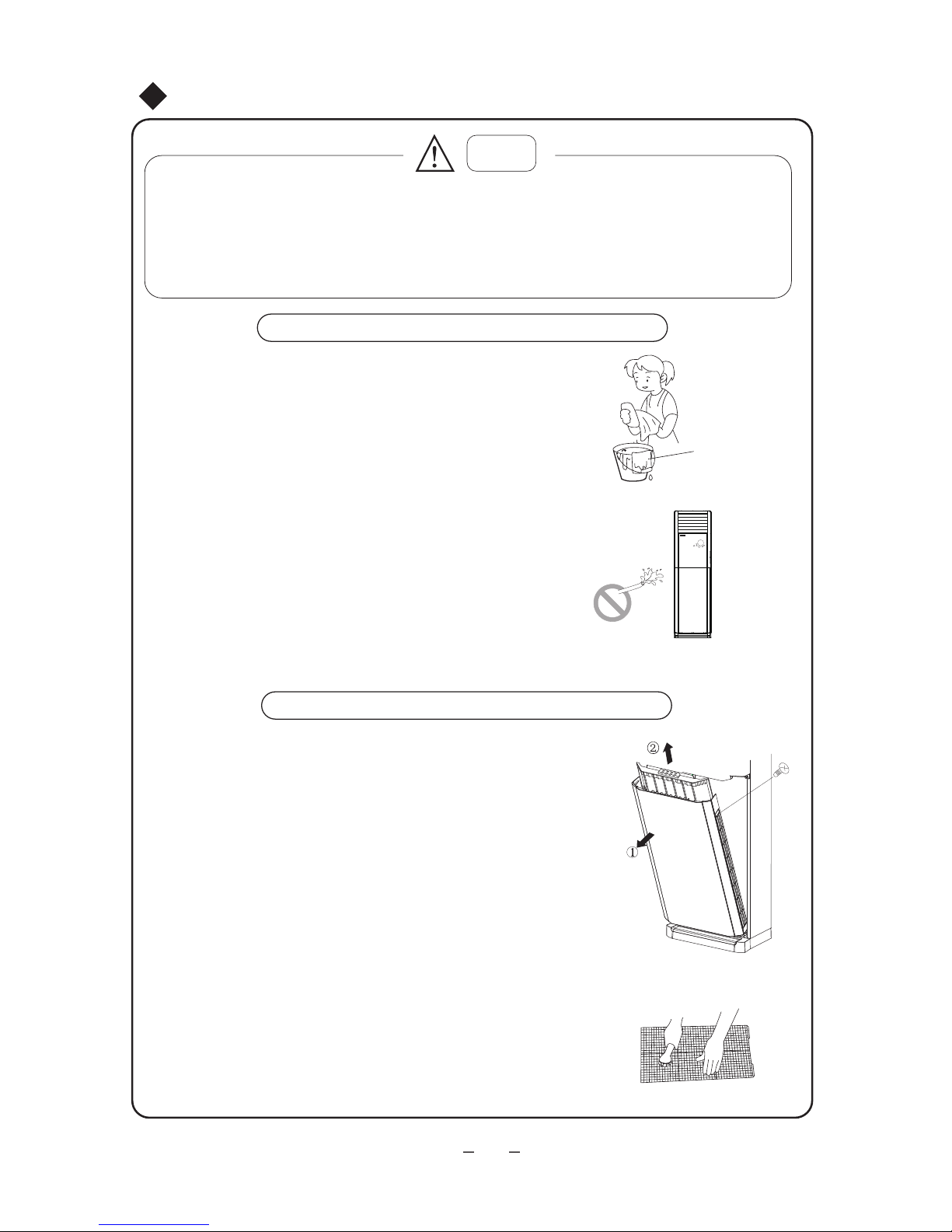
Clean and Care
Caution
1.Turn power off and pull out the power plug before cleaning air conditioner,or it may
cause electric shock.
2.Never sprinkle water on the indoor unit and the outdoor unit for cleaning because it
can cause electric shock.
3.Volatile liquid (e.g. thinner or gasoline) will damage the air conditioner,so wipe the units
with a dry soft cloth, or a cloth slightly moistened with water or cleanser.
Clean the unit
Cut power off before cleaning
Use soft cloth when cleaning cabinet
Don't spray water on indoor unit
Turn off the air switch after unit stops running.
If the unit is very dirty, dip cloth into warm water
below and dry the cloth before cleaning it.
(As shown in Fig.7)
Spraying water will damage microcomputer and
circuit board in the unit (As shown in Fig.7)
Fig.7
Dry the cloth
before cleaning
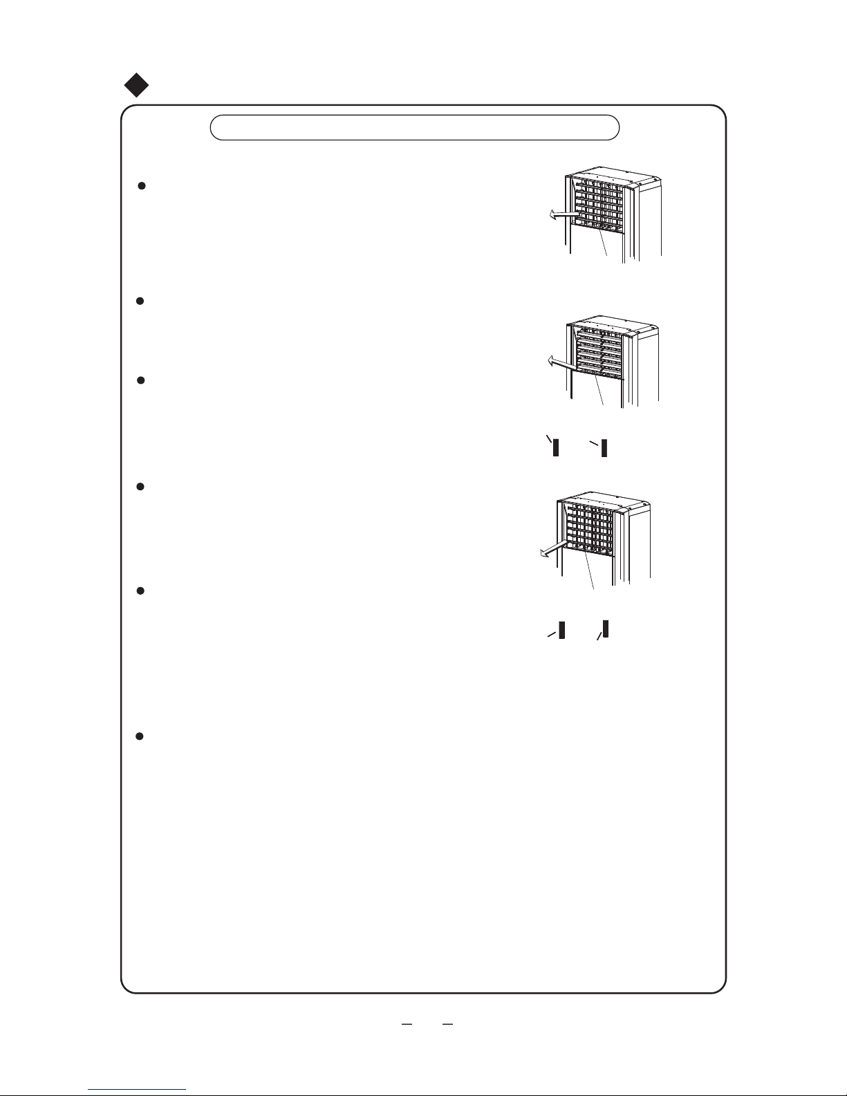
Clean the air filter(once every 2 weeks)
Fig.8
Disassembly of air filter
As shown in Fig.8,take out the decorative strip at 1) position ,
and unscrew the screw.After opening the glass panel unscrew
the screws fixing the air filter.At last pull out the air filter from
the arrow direction.
Cleaning the filter
Slightly flat the filter or clean the filter with electric
①
②
cleaner.If too much dust on the filter,clean it with
a little neutral detergent or warm water.After that,
dry the filter and reinstall it,as shown in Fig.8.
NOTE: Do not dry the filter by exposing it under direct
sunshine or near a heating oven, or it may get deformed.
20

Check before use
Be sure that nothing obstructs the air outlet and intake vents
Check that whether the batteries of air conditioner are changed
or not.
Check that whether the installation stand of the outdoor unit is
damaged or not. If damaged, please contact the dealer.
Maintenance after use
Clean the filter and indoor and outdoor units' bodies.
Clear dust and obstruction from the outdoor unit.
Repaint the rubiginous place on the outdoor unit to prevent it from spreading.
Cut the power off.
①
②
Check that whether earthing wire is properly connected or not.
③
④
①
②
③
④
Clean and Care
21
●
Troubleshooting
CAUTION
Don't attempt to repair the air conditioner by yourself.It may cause the electric shock or
fire. Please check the following items before asking for repair.It can save your time and
money.
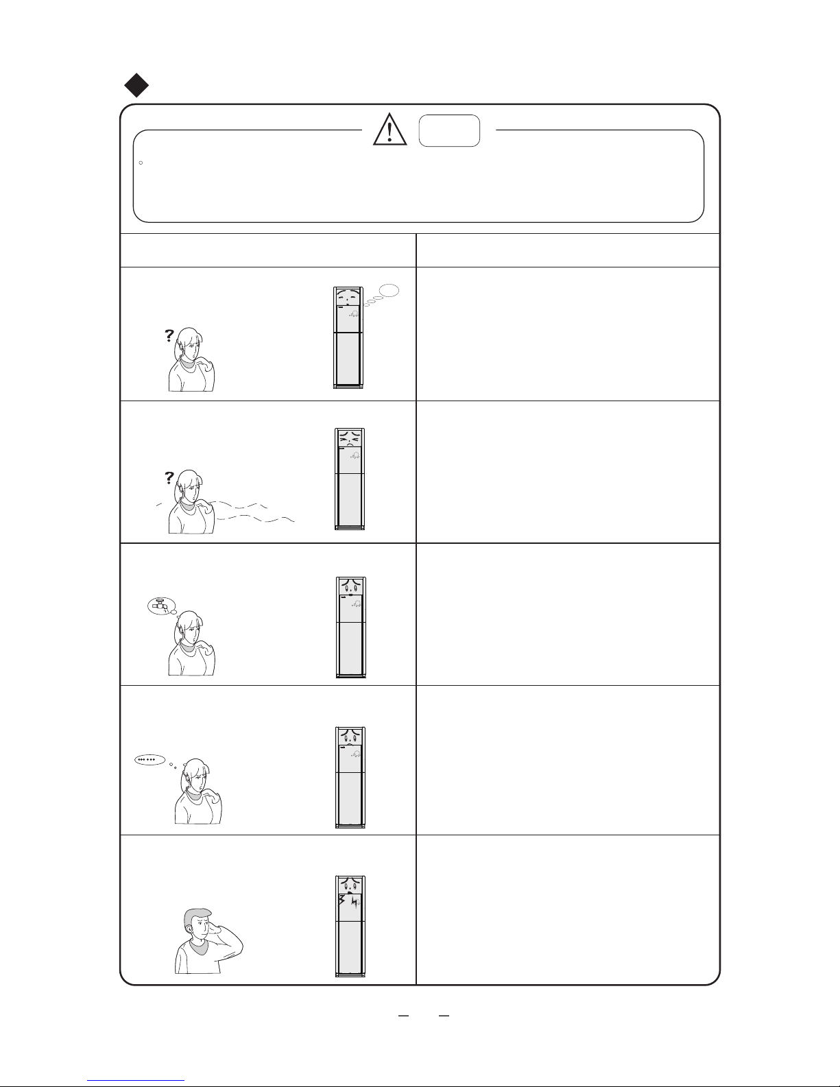
Phenomenon
Troubleshooting
Once the air conditioner is stopped, it will not
operate in approximately 3 minutes to protect
itself.
Not operate immediately when
the air conditioner is restarted.
There's unusual smell blowing
from the outlet after operation
is started.
The unit has no peculiar smell by itself. If has,
that is due to the smell accumulated in the
ambient.
Solution method: Cleaning the filter.
If problem still has, so need to clean air conditioner.
Sound of water flow can be heard
during the operation.
The air conditioner is started, when it is running the
compressor started or stopped running, or the unit
is stopped, sometimes there is swoosh or gurgle,
the sound is due to refrigerant flowing they are not
malfunctions.
In COOL mode, sometimes the mist emitted
from the air outlet vent.
When the indoor
temperature and humidity are
very high, this phenomenon would happen. This
is caused by the room air is swiftly cooled down.
After running for a while, indoor temperature and
humidity will fall down, the mist will die away.
Creaking noise can be heard when start or stop
the unit.
This is caused by the deformation of plastic due to
the changes of temperature.
Waiting
22
(Please contact with authorized maintenance
center.)
Troubleshooting
Phenomenon
Troubleshooting
The unit can not run
Has the power been shut down?
Is the circuit protection device tripped off or
not?
Breaking off
Is voltage higher or lower?
(Tested by professionals)
Is the Timer correctly used?
Cooling (Heating) efficiency is not good.
Is Temp. setting suitable?
Were inlet and outlet vents obstructed?
Is filter dirty?
Are the windows and doors clothed?
Did Fan speed set at low speed?
Is there any heat sources in the room?
Wireless remote control is not available
The unit is interfered by abnormal or frequent
functions switchover occasionally the controller cannot operate. At this time, you need to
pull out of the plug, and reinsert it.
If water leakage in the room
The air humidity is on the high side.
Condensing water over flowed.
The connection position of indoor unit drainage
pipe is loosed.
If water leakage in outdoor unit
Noise from indoor unit emitted
The sound of fan or compressor relay is
switching on or off.
When the defrosting is started or stop running,
it will sound. That is due to the refrigerant flowed
to the reversed direction.
●
●
●
●
●
●
●
●
●
●
●
●
Is it in its receiving range? Or obstructed?
●
●
●
●
●
● Whether the wireless remote control is
damaged.
●
●
●
●
The water adhered on the heat exchanger will
drop during heating operation.
23
To check the voltage in wireless remote
controlinside is charged, otherwise to
replace the batteries.
When the unit is running in COOL mode, the
pipe and connection of pipe would be
condensed due to the water cooled down.
During heating or defrosting operation, the
melted water will blow out.
● In heating procedure, when the heat exchanger
temperature of indoor unit is low, it stops blowing
in order to avoid blowing cool air (within 90 s).
▲
▲
▲
▲
▲
Phenomenon Troubleshooting
Indoor unit can not blow
Immediately stop all operations and plug out, contact the dealer in following situations.
There is harsh sound during operation;
The terrible odors emitted during operation;
Water is leaking in the room;
Air switch or protection switch often breaks;
Carelessly splash water or something into
Stop running and pull out of the plug
air conditioner.
● When heating, if the outdoor temperature is low
and in high humidity, there is much frost formed
in the outdoor unit heat exchanger, the unit will
automatically defrost, indoor stop blowin
g fan
about 10mins, during the defrosting procedure,
there will be water or vapor emitted.
Moisture formed on air inlet grill
If air conditioner is running in a high humidity
for a long time, the moisture may condense on
the air outlet grill and drip off.
Troubleshooting
H1: Defrosting
It is normal.
●
●
24
If power indicator blinks, the unit will display E1
If power indicator blinks, the unit will display E3
If power indicator blinks, the unit will display E4
If power indicator blinks, the unit will display E5
E1: System high-pressure protection
●
E3: System low pressure protection
●
E5: Over current protection
●
E4: Air exhaust pipe high temperature
●
protection
If power indicator blinks, the unit will display F1
If power indicator blinks, the unit will display F2
If power indicator blinks, the unit will display F3
If power indicator blinks, the unit will display F4
If power indicator blinks, the unit will display F5
●
●
●
●
●
F1: Indoor ambient sensor malfunction
F2: Indoor tube temperature sensor malfunction
F3: Outdoor ambient sensor malfunction
F4: Outdoor tube temperature sensor malfunction
F5: Air exhaust sensor malfunction
●
●
●
●
●
●
Important notices
1. The unit installation work must be done by qualified personnel according to the local rules
and this manual.
Basic requirements for installation location
Installation at the following places may cause failure of the air conditioner. Please contact
installation and service agency if the installation at such places cannot be avoided.
A region with saline-sodic soil near the sea;
An environment with special conditions.
A place with sulphide gases (such as sulphur spring);
A place full of machine oil;
A place with high frequency facilities, such as radio equipment, electric welder or
medical equipment;
9. Ensure the installation of indoor unit is in conformity with the requirements of installation
dimension drawing;
3. Ensure that airflow can reach every conner of the room.
1. A place where noise and airflow generated by air exhaust do not affect the neighbors,
animals and plants.
5. Choose a place far away the direct sunshine or strong wind.
Choose a place far away from heat source, steam and inflammable gases.
6.The indoor unit shall be in conformity with the requirements of installation diagram,
and ensure sufficient clearance and space for service and maintenance.
8. Please select the place keep out of the children's reach.
9. Select the place which do not influence the communal path way and the appearance
of the city.
7. The height of connection pipe should be within 5meters, and the length of it should be
within 10meters.
1. Select a place, avoid the inflammable gas produce or leakage.
2. Select a place avoid the water vapor or oil sprayed on the unit.
4. Choose a place so that the connection pipe could be easily pulled out.
5. Select the place where the airflow of the unit can not be blocked.
6. Select the position where the few outer air influenced.
7
. Select the firm and flat ground.
2.When removing the unit to the other place, please firstly contact with the local maintenance
center.
Installation Service-Notes for Installation
25
8. Ensure sufficient clearance and space for service and maintenanc.
2. Ensure good ventilation of outdoor unit.
3. No obstacles near the outdoor unit obstructing the air intake and air exhaust of the unit.
4. The installation position shall be able to withstand the weight and vibration of the outdoor unit.
Installation location of indoor unit
Installation location of outdoor unit
(2) The capacity of wire diameter should be 1.5 times larger than the unit max. current.
(3) Installed the creepage protector with enough capacity.
(4) Make sure to divide the branch circuit for the special circuit.
1. First install wire of outdoor unit and then wire of indoor unit. After finishing wiring and
piping, connect the unit to the power supply.
2.Please strictly follow the instruction of this manual when installing indoor unit and its
piping.
3.The unit is subject to change without prior notice.
4.Please read this manual carefully before installation.
The unit power is large, the power supply circuit supplied for the unit should accord with
the following:
(1) Installed the air switch with suitable capacity, please refer to the following, the air switch
must have the functions of magnetic tripping and heat tripping.(Note: never use the fuse
to protect the branch circuit.)
(5) The min. clearance between combustible surface and the air conditioner is 1.5 meters.
1. It should be connected with the special earth device on the building, it should be
installed by the professional personnel. There should be enough capacity of creepage
protector and air switch. (please refer to the following table)
2. The power supply must use the rated voltage and special circuit.
3. The diameter of the power wiring should be large enough. (Please refer to the following
table)
4. The wiring work should conform to relative standard.
5. The ground must be connected.
6. Don't pull the power wire strongly.
●
●
Please pay attention to surrounding conditions (eg. Ambient temp., direct sun shine,
rain drops etc.)
Power cord or power connecting wire must be copper cored cable according with
(6) The indoor unit and outdoor unit must be reliably earthed.
●
national criteria.
The indoor unit and outdoor unit must be reliably earthed.
Notes for Installation
Electric wiring
Requirements for electric safety
Note:
Air switch capacity
Models
.
.
32A
26
25A
①
②
③
④
Requirements for earthing
1.The air conditioner is the first class electric appliance:
2.The yellow and green dual color wire in the air conditioner is earth wire, it cannot be used for other purposes, do not cut
off it. Do not fix it by the tapping screw: otherwise, it can cause the electric shock.
3.Please do not connect the earth wire to the place:The power supply must be reliabbly earthed.
Water pipe
Gas pip
e Drainage pipe
The place where is unreliable suggested by the professional.
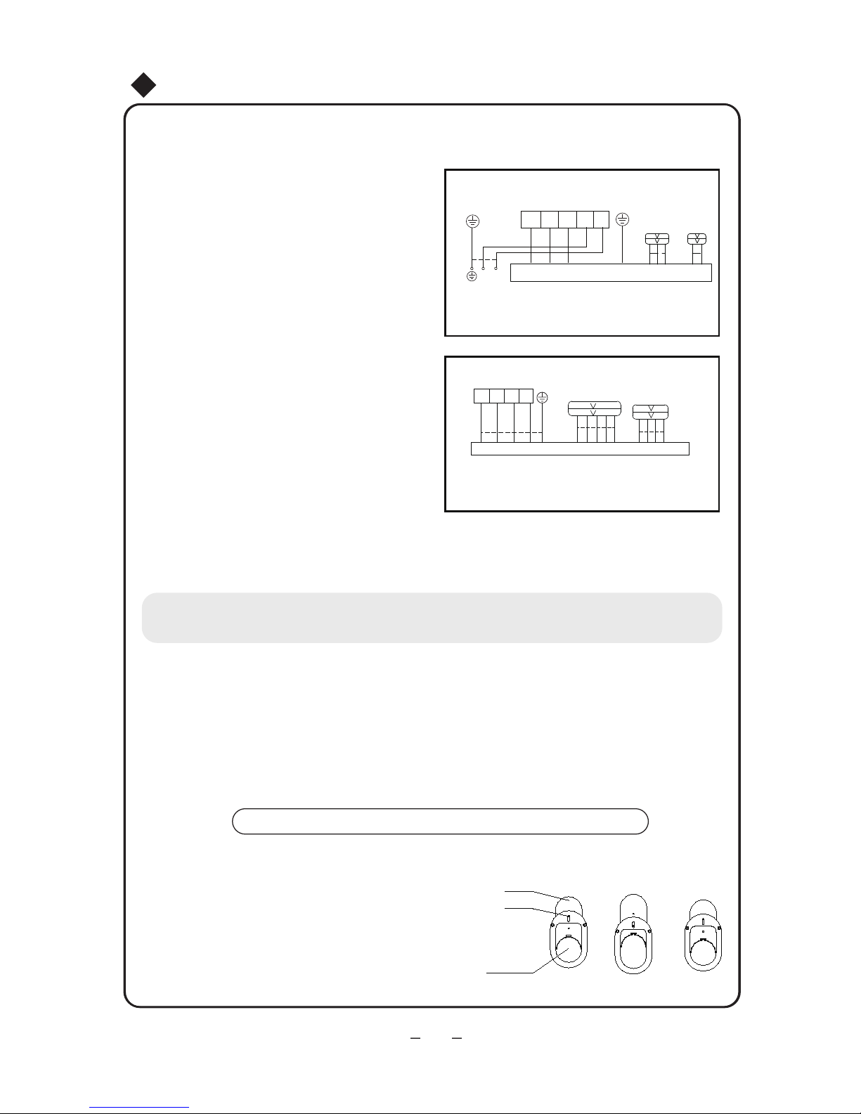
Notes for electric wiring:
1. Special circuit must be used for power supply.
2. The circuit must be installed by special serviceman.
3. Please do the wiring according to the following wiring
diagram. The screws must be tightly fastened, the
slippery screws must be changed, the tapping screw
cannot be used for electric wiring.
4. Please wiring according to the circuit diagram on the unit.
5. Adopts the cables which are attached with the unit, please
do not to change the cables optionally, and do not change
the length and ends of the cable, if need to adjust, please
contact with the local after-sales service center.
6. For the power cord which is without the plug, that cannot be
connected the plug for using.
7. The electric wiring connection of indoor and outdoor should
not be affected by the stretch and bending.
8. is the symbol of earthing, it denotes that the yellow-green
dual wire only can be connected with the place with the symbol.
9. After the electric installation completed, make sure to use wire
clamp to fix the power cord, power supply connection cable and
signal cable tightly, and ensure that there is enough space in the
fix position and each connection terminals of the lead wires.
10.Please use about a half kilogram of force, to check whether each
lead wire is installed well. When checking the air connector, please
enclasp it, and check each lead wire of which is connecting with the
connector.
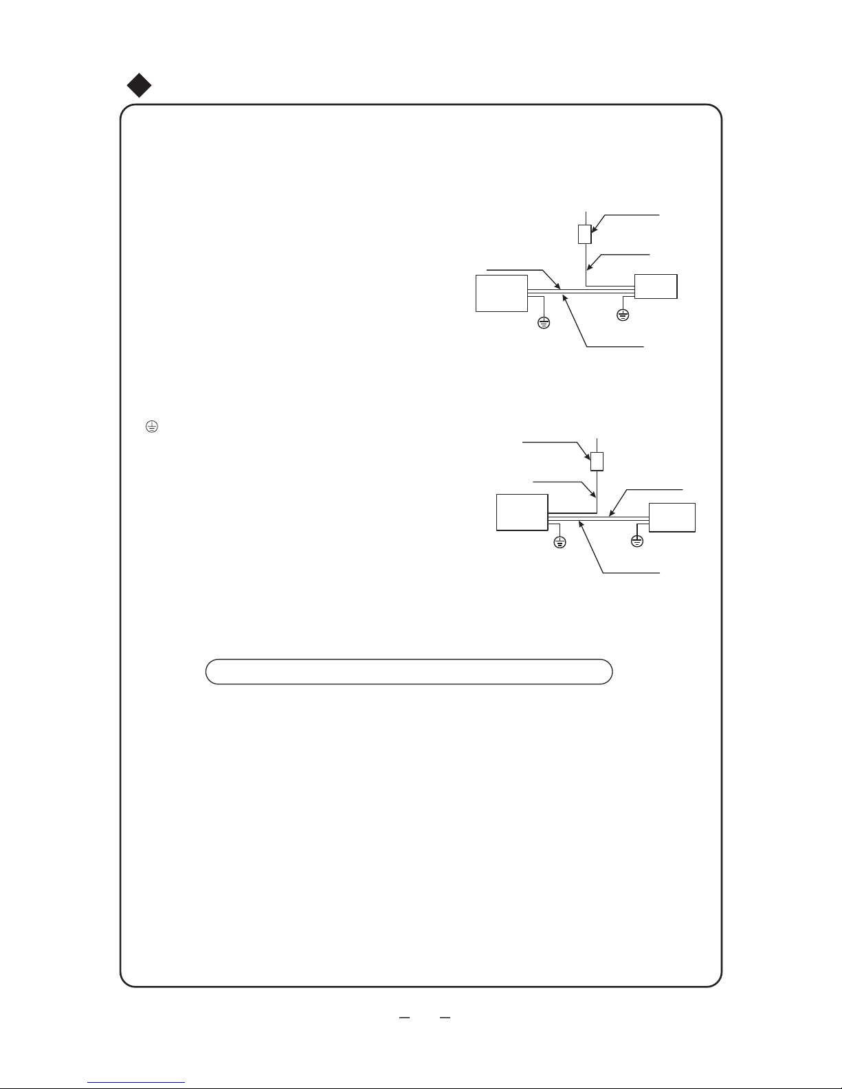
Power supply
Air switch
Power cable
Signal control cable
Earth
Indoor
unit
Installation diagram, please refer to the following.
Note:the unit should be correctly earthed to avoid
interference to the complete unit and ensure
personal safety.
Notes for Installation
Indoor
Outdoor
Earth
Signal control cable
Power cable
Air switch
Power supply
unit
unit
Connection cable
Power supply indoors
and outdoors
Connection cable
Power supply indoors
and outdoors
Outdoor
unit
For 380V 3N~ model:
For 220V~ model:
27

Installation dimension diagram
Space to the rear side
Air outlet side
Space to the wall: (30cm at
least for the pipe side)
Space to the ceiling
200cm above
Installation Dimension Diagram
28
Space to the obstruction
Space to the wall
Air outlet side
Space to the wall
Air inlet side
10cm above
200cm above
60cm above
10cm above
24K
30cm
10cm
5cm
60cm above

Installation dimension diagram
Space to the rear side
Air outlet side
Space to the wall: (30cm at
least for the pipe side)
Space to the ceiling
200cm above
Installation Dimension Diagram
29
48K
Space to the obstruction
Space to the wall
Air outlet side
Space to the wall
Air inlet side
10cm above
200cm above
60cm above
10cm above
30cm
10cm
5cm
60cm above

Installation of connection pipe
Before wiring and piping, please remove the
filter after opening the glass panel.
1.As shown in Fig.9,take out the decorative
strip at position 1 and then unscrew the
screws.Remove the screws fixing the filter
after opening the glass panel.At last take
out the filter along the arrow direction at
position 3.
2.During piping and wiring in the left and
at the rear side,the attached accessories
should be used,as shown in Fig.11.
Installation of drainage pipe
1. Make sure drainage pipe is led outdoors (discharge side).
2. Butt-joint drainage pipe in the unit with blowing drainage pipe and fix them with
insulated tape.
3. If the drainage pipe should be wrapped with heat-preservation material (at least
9mm thickness), and then wrap it with tape to prevent air from entering into the
pipe,which will cause condensation.
4. After connecting, check if water can discharge properly or if there is any leakage.
(As shown in Fig.12)
Electric connection
1.Open the glass panel.
2.Unscrew the screws fixing elecrtic
box cover and make it exposed,as
Fig.11
Fig.12
Drainage pipe
Blowing
drainage pipe
Drainage piping hole
Wrapping tape
Connection pipe /
(Flare-end connection)
Drainage pipe
Refrigerant pipe
(Flare-end connection)
Refrigerant pipe
Electric box cover
Sketch of indoor unit
3.Pass the power connection wire
through the pipe-through hole of
indoor unit.
shown in the right figure.
Installation of Indoor Unit
30
Fig.9
Fig.10
Drainage
pipe
Flare-end connection
Connection
pipe
Flare-end connection
●
●
●
●
●
Note:
When the connection wire length isn’t enough, please contact with the appointed service shop for buying a dedicated
electric wire with enough length, the connection isn’t allowed between the wire.
The wrong wiring connection isn’t allowed, it may cause the malfunction of the components.
Tighten the terminal screw.
After tightened the screw, and slightly pull the electric wire to confirm whether it is firmed or not.
Wrong earth wire connection may cause electric shock.
The electric wire covering plate must be fixed well, and tighten the connection wire, if the wire cover-
ing plate isn’t installed well, that may lead the dust, moisture enter in or due to the outside force
impact, it may cause fire or electric shock.
4. According to the diagram for wiring,
according to the marks on wire board
for connection correspondingly,as
shown in Fig.13.
5. Place the section with sleeve of the
power connection wire into the wire
groove, then cover the electric box
cover, tighten the fixing screw, and
tighten the connection wire with clamp.
6. For the unit with signal wire, the signal
wire is connected with indoor unit via
connector. Clasp the section of signal
wire with sleeve with the wire clamp.
Outdoor unit terminal board
Fig.13
Wire connection according to this diagram:
7. Recover the electric box cover.
Installation of Indoor Unit
●
Screws
Hole
Baffle
Installation of baffle
1.Loosen the screws and adjust the baffle position up
and down to clamp connection pipe/drainage pipe
as much as possible.
Fig.14
2. Tighten the screws.
Please install it after installtion of connection pipe
and drainage pipe according to Fig.14.
31
48K
24K
N
L
blue
blue
blue
brown
brown
brown
black
black
vioet
yellowgreen
yellow-
green
yellow-
green
L1 L2 L3 N
Outdoor unit connection
N(1)
2
3 L N

Notes for piping
Pipes for refrigerant and drainage pipe
should be insulated to avoid frosting
and dripping.
Note:
Don't bend the bendable pipe back and
forth more than 3 times. Insulate all
exposed parts of the flare-end connection
joint and refrigerant pipe. (As shown in Fig.16)
1. Both of the indoor and outdoor units
adopt flare-end connection. Refrigerant
pipe as shown below is used to connect
indoor and outdoor units.
2.Check valve of the outdoor unit should be closed
(in factory). Every time of connection,screw cap
at check valve should be unscrewed and then
connect it with flare-end pipe immediately (within
5 min).Otherwise, dust, moisture and other impurities
may go into the pipe and cause malfunction.
1.The part with bendable pipe should be used in
indoor side.
2. The bending angle should not be more than 90.
3. It's better for the bend to be in the middle of the pipe
and the radius of the bend is the bigger the better.
4. Don't bend the bendable pipe more than three times.
Notes for bendable pipe:
When bending the pipe
1. Cut some part of the insulation pipe at the place of
the bend (and wrap with polythene tape after bending).
2. Make radius of the bend as big as possible so that the
pipe will not get flat or broken.
3. Tighten the pipe bending by the rubber bender.
(As shown in Fig.15)
Fig. 16
Fig. 17
Polythene tape
Insulation cover
Bend the pipe with thumbs
Min. radius: 100 mm
Fig.15
●
●
Installation of Indoor Unit
Indoor unit
Bendable pipe
Outdoor unit
Note: Before fastening nut of the flare-end pipe, please apply
some refrigerant oil to the end of the pipe and the joint.
When using copper pipe bought locally
Check valve of the outdoor unit should be closed completely
(in the factory). After connection of indoor and outdoor units
via connection pipe, discharge the air from service vent of
low-pressure check valve of the outdoor unit. After that,screw
down the nuts to service vent.
After step 1 or 2 above
Check valve of the outdoor unit should be fully opened to
ensure smooth flow of connection pipe between indoor
and outdoor units.
Loosen the roll of pipe
Straighten end of pipe
Install the big handle.
●
●
32

2.
●
B
C
D
A
Installation of connection pipe
1.
Align the center of the piping flare with the pyramidal face of relevant valve.
Screw in the flare nut by hand and then tighten the nut
with spanner and torque wrench refer to the following.
Spanner
Torque wrench
Indoor unit piping
Taper nut
Piping
NOTE: Firstly connect the connection pipe to indoor unit, then to outdoor unit; pay attention
to the piping bending, do not damage the connection pipe; the joint nut couldn’t tighten too
much, otherwise it may cause leakage.
Exhausting(with A5mm hexagon wrench)
When using refrigerant of outdoor unit:
1. Tighten nuts A, B, C, D substantially.
2. Remove cover from check valve A (As show
in Fig.18)
3. Twist open core of liquid valve B with hexagon
wrench, and at the same time hold screw driver
against core of gas valve A to let gas out. After
15 seconds of exhausting and refrigerant appears,
close one-way valve and tighten bonnet.
4. Fully open cores of both liquid valve and gas valve,
tighten bonnet, then check with soap water or leakage
detector to see if there is any leaking in the joints of
piping between indoor and outdoor units.
Fig.18
Gas side
Outdoor unit
Indoor unit
Check valve Pipe joint
Joint nut
Limited block
Bonnet
Valve sterm
One-way valve
Installation of Indoor Unit
Hex nut
Tightening torque (N.m)
Ф 9.52
Ф 16
60~65
35~40
Ф 6
15~20
Ф 12
50~55
Ф 19
70~75
Air discharge method
Length of connection pipe Charge volume of additional refrigerant
Use refrigerant of Below 5m Volume on nameplate
Use vacuum pump
Use vacuum pump
5-15m
20-30m
outdoor unit
24K model Volume on nameplate+30g/m
48K model Volume on nameplate+100g/m
33
-76cmHg
Gas valve
Manometer
Vacuum
High-pressure
Charging hose
valve (Hi) closed
pump
Low-pressure
valve (Lo) Open
Liquid valve
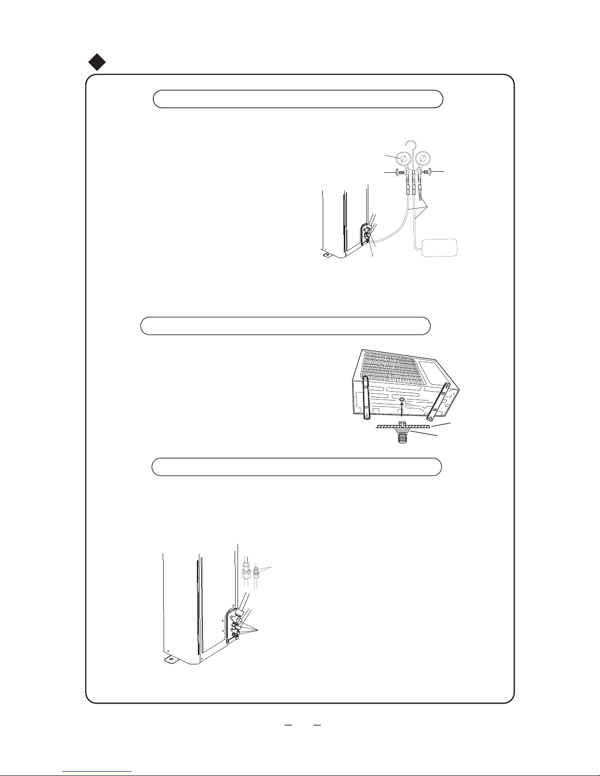
Installation of Outdoor Unit
When using vacuum pump
Fig.19
1. Connect charging hose of to charge nozzle. (both cores of
gas and liquid valves should be shut down tightly.)
2. Connect joint of charging hose to vacuum pump.
3. Fully open low-pressure valve(Lo) of manometer.
4. Make vacuum pump operate for 15 min above.Close lowpressure valve(Lo) to stop vacuum pump after confirmation
of -1.0X10 pa(-76cmHg) at manometer .Then check if there
is air in the pipe(keep for 2 min to see if indicated needle of
manometer returns).If there is ,re-operate the vacuum pump
after restoration.
5
6. Fully open the cores of gas valve and liquid valve.
5. Remove charging hose from gas valve.
7. Tighten bonnet of gas valve and liquid valve and nut of charge
nozzle.(As shown in Fig.19)
Outdoor condensation drainage (Heat pump type only)
Outdoor drain elbow
Base plate of
When the unit is heating, the waste water formed in the outdoor
unit can be drained out reliably through the drain hose.
Installation:
Install the outdoor drain elbow in the Φ25
on the base plate as below, and joint the
drain hose to the elbow, so that the waste
water formed in the outdoor unit can be
drained out to a proper place.
outdoor unit
Coat soap water at the gap between connection pipes to see if there is any leakage.If
there is air bubble at this position,it should leak.(As shown in Fig.20).Leakage detector,
Fig.20
Leakage detection
Leakage detection spot of indoor unit
Leakage detection spot of outdoor unit
if possible,can be used.
34
Installation of Outdoor Unit
35
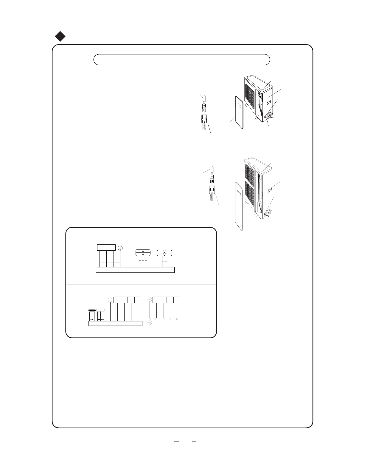
Wiring method
1. Remove the front side plate.
2. Please refer to the electric wiring connection
of the indoor unit, then fix them with wire
clamp.(As shown in Fig.21)
Fig.21
Terminal board
Rear side
Wiring hole
Power
connecting
cable
Signal wires
Front side
plate
Signal wire of
the indoor unit
Signal wires
plate
24K:
48K :
Signal wire of
the indoor unit
Signal wires
Terminal board
Rear side
plate
Wiring hole
24K
blue
brown
black
yellowgreen
N1 2 3
Outdoor unit connection
Indoor unit connection
L2N L1
L3 L2 L1
N
L3 L2N L1L3
blue
vioet black brown
blue
vioet black brown
yellowgreen
yellowgreen
POWER
48K

1.
(1)
(2)
(3)
(4)
2.
(1)
(2)
Check after installation
Has it been fixed firmly?
The unit may drop, shake or emit noise.
Have you done the refrigerant leakage test?
It may cause insufficient cooling(heating)
capacity.
Is heat insulation sufficient?
It may cause condensation and dripping.
Is water drainage well?
It may cause condensation and dripping.
Is the voltage in accordance with the rated
voltage marked on the nameplate?
It may cause electric malfunction or
damage the part.
Is the electric wring and piping connection
installed correctly and securely?
It may cause electric malfunction or
damaged the part.
Has the unit been connected to a secure earth
connection?
It may cause electrical leakage.
Is the power cord specified?
covered?
It may cause electric malfunction or damage
the part.
Is the inlet and outlet of piping hole been It may cause insufficient cooling(heating)
capacity or waster eletricity.
Has the length of connection pipes and
refrigerant capacity been recorded?
The refrigerant capacity is not accurate.
Test operation
Before test operation
Do not switch on power before installation is finished completely.
Electric wiring must be connected correctly and securely.
Cut-off valves of the connection pipes should be opened.
All the impurities such as scraps and thrums must be cleared from the unit.
Test operation method
Switch on power, press ON/OFF button on the remote controller to start the operation.
Press MODE button to select the COOL, HEAT, FAN to check whether the operation
is normal or not.
Test Operation and Check after Installation
Items to be checked Possible malfunction
36

Activate your warranty.....
in
5
simple
steps!
For the electronic
warranty submission
please use the following link
Scan here for the
warranty form
http://www.inventoraiconditioner.com
/warranty-inventor
Select the product type
(airconditioner or appliance) for
which the warranty will be activated
Choose the warranty that
corresponds to your product
purchase
Fill in the required information
(owner, retailer and appliance)
and press send
You will receive a confirmation
e-mail for the activation of
your warranty
Connect to the following link
http://www.inventorairconditioner.com/warranty-inv entor

Περιεχόμενα
Σημειώσεις για την χρήση
....................................................4
Ονομασίες για τα τμήματα της μονάδας
..................................6
Χρήση του τηλεχειριστηρίου
................................................12
Χρήση και συντήρηση
Καθαρισμός και φροντίδα
..................................................20
Έλεγχος προβλημάτων ......................................................22
Διάγραμμα διαστάσεων εγκατάστασης...................................28
Εγκατάσταση της εσωτερικής μονάδας
..................................30
Εγκατάσταση της εξωτερικής μονάδας ..................................34
Δοκιμαστική λειτουργία και έλεγχος μετά την εγκατάσταση.........36
Εγκατάσταση & Επισκευή
Προσοχή για την χρήση .......................................................1
Σημειώσεις για την εγκατάσταση ..........................................25
Ρύθμιση της κίνησης των περσίδων......................................17
Εισαγωγή στις ειδικές λειτουργίες .........................................19
Αυτό το σύμβολο σηματοδοτεί
απαγορευμένες ενέργειες.
Αυτό το σύμβολο σηματοδοτεί
ενέργειες που πρέπει να γίνουν.
Οι εικόνες της μονάδας μπορεί να διαφέρουν από το πραγματικό μοντέλο.
Ανατρέξτε στο πραγματικό μοντέλο.
Ονομασία και λειτουργία για τα πλήκτρα της μονάδας ................8
Μην απορρίψετε το προϊόν ώς οικιακό απόρριμα. Απαιτείται
ειδική περισυλλογή για επεξεργασία.
Η μονάδα δεν θα πρέπει να λειτουργείται από άτομα με ειδικές ανάγκες και
παιδιά ή άτομα με έλλειψη γνώσης και εμπειρίας, παρά μόνο αν επιβλέπονται
από κατάλληλο άτομο υπεύθυνο για την ασφάλειά τους. Τα παιδιά πρέπει να
επιβλέπονται ώστε να μην παίζουν με τη μονάδα.

★
★
★
Παρακαλείσθε να διαβάσετε προσεκτικά τα ακόλουθα πρίν τη χρήση.
ΠΡΟΕΙΔΟΠΟΙΗΣΗ
Όταν υπάρχει κάποια ανωμαλία
όπως οσμή καμμένου, παρακαλείσθε
αποσυνδέστε το από το ρεύμα άμεσα
και επικοινωνήστε με το τμήμα
επισκευών.
Πρέπει να εγκατασταθεί ειδικό
κύκλωμα παροχής ρεύματος για την
αποφυγή πυρκαγιάς.
Κατά τον καθαρισμό, αποσυνδέστε
το από το ρεύμα.
Σε αντίθετη περίπτωση θα προκληθεί
ηλεκτροπληξία ή φθορά.
Αποσυνδέστε το κλιματιστικό από
την πρίζα εάν δεν πρόκειται να χρησιμοποιηθεί για μεγάλο χρονικό
διάστημα.
Μην χρησιμοποιείτε φθαρμένο ή
μη ενδεδειγμένο καλώδιο
Σε αντίθετη περίπτωση, μπορεί να
προκληθεί υπερθέρμανση και πυρκαγιά
Μην χρησιμοποιείτε πολύπριζο ή
μπαλαντέζα για την τροφοδοσία.
Μην χειρίζεστε τη μονάδα με
βρεγμένα χέρια
Εάν συνεχίζει να υπάρχει η ανωμαλία, η
μονάδα μπορεί να υποστεί ζημιά και να
υπάρξει ηλεκτροπληξία ή πυρκαγιά.
Μην κόβετε ή προκαλείτε φθορά
στο καλώδιο ρεύματος και στο καλώδιο
επικοινωνίας. Εάν έχουν υποστεί φθορά,
πρέπει να αντικατασταθούν τα με το
αντίστοιχο ειδικό καλώδιο από
εξειδικευμένο τεχνικό.
Αποσυνδέστε από
το ρεύμα
Προσοχή για την χρήση
1
Σε αντίθετη περίπτωση, μπορεί να
προκληθεί ηλεκτροπληξία.
Σε αντίθετη περίπτωση, μπορεί να
προκληθεί πυρκαγιά από την
συσσώρευση σκόνης
Η παροχή ρεύματος με ειδικό
κύκλωμα με την σωστή ασφάλεια.
Για την προστασία της μονάδας μην
την ανοιγοκλείνετε συχνα.
Η παροχή ρεύματος και η τάση
πρέπει να είναι σταθερές. Τα ηλεκτρικά
εξαρτήματα μπορούν εύκολα να
πάθουν βλάβη από την υψηλή τάση.
Το ψυκτικό σύστημα θα πάθει ζημιά,
και ο συμπιεστής και τα ηλεκτρικά
εξαρτήματα δεν θα λειτουργούν εάν
η τάση είναι πολύ μικρή.

2
★
★
★
★
★
★
★
★
Γείωση: η μονάδα πρέπει να
γειωθεί επαρκώς: Τα καλώδια της
γείωσης πρέπει να συνδεθούν με την
ειδική συσκευή των κτιρίων.
Κατά την λειτουργία της μονάδας,
μην αφήνετε ανοιχτα τις πόρτες και
τα παράθυρα.
Βεβαιωθείτε ότι η εγκατάσταση
είναι αρκετά σταθερή.
Μην ανεβαίνετε στην εξωτερική
μονάδα και μην βάζετε τίποτα πάνω της.
Μην επιχειρήσετε επισκευές στο
κλιματιστικό μόνοι σας.
Υπάρχει κίνδυνος πτώσης των αντικειμένων ή των ανθρώπων.
Η λανθασμένη επισκευή μπορεί να
προκαλέσει ηλεκτροπληξία ή πυρκαγιά,
επομένως πρέπει να επικοινωνήσετε με
το τμήμα επισκευών.
Σε αντίθετη περίπτωση, μπορεί να
προκληθεί πτώση της μονάδας και
τραυματισμό ανθρώπων.
Ποτέ μην φράζετε τους αεραγωγούς
της εσωτερικής/εξωτερικής μονάδας.
Κρατήστε τα δοχεία συμπιεσμένου
αερίου κλπ τουλάχιστον ένα μέτρο
μακρυά από την εσωτερική μονάδα.
Μπορεί να προκαλέσει πυρκαγιά
ή έκρηξη.
Μπορεί να μειώσει την αποδοτικότητα
της μονάδας
Μπορεί να μειώσει την αποδοτικότητα,
να προκαλέσει παύση της μονάδας ή
ακόμα και πυρκαγιά
Μην εισάγετε ποτέ ξένα σώματα στο
κλιματιστικό για την αποφυγή βλάβης.
Ποτέ μην εισάγετε τα χέρια σας στους
αεραγωγούς της εσωτερικής/εξωτερικής
μονάδας.
Η χρήση της βάνας στην εξωτερική
μονάδα, πρέπει να γίνεται μόνο από
εξειδικευμένους τεχνικούς για την
αποφυγή φθοράς στον συμπιεστή και
διαρροής του συστήματος.
Εάν δεν υπάρχει γείωση, ζητήστε από
εξειδικευμένο τεχνικό να την εγκαταστήσει. Ακόμη, μην συνδέετε τα καλώδια
με αγωγούς αερίου, νερού αποχέτευσης
ή άλλα ακατάλληλα σημεία τα οποία οι
τεχνικοί ενδεχομένως να μην
αναγνωρίσουν.
Προσοχή για την χρήση

Κρατήστε την κατάλληλη
διαφορά θερμοκρασίας
μεταξύ εσωτερικής και
εξωτερικής μονάδας
★
★
★
★
★
Μην βάζετε τα χέρια σας στην εισαγωγή και εξαγωγή
αέρα.
Η ρίψη νερού στην μονάδα μπορεί να προκαλέσει
ηλεκτροπληξία και βλάβη.
Μην κατευθύνετε την ροή του αέρα προς τα ζώα
και τα φυτά. Μπορεί να έχει κακή επιρροή σε αυτά.
Μην κατευθύνετε την ροή του αέρα προς το σώμα σας
για μεγάλο χρονικό διάστημα και μην ορίζετε υπερβολικά
χαμηλή θερμοκρασία.
Μην χρησιμοποιείτε το κλιματιστικό για άλλους σκοπούς,
όπως στέγνωμα ρούχων, συντήρηση τροφίμων,κλπ.
Μην χτυπάτε την γυάλινη πόρτα μα βαριά αντικείμενα για
την αποφυγή φθοράς.
Μην τοποθετείτε θερμάστρες κοντά στο κλιματιστικό.
Μπορεί να υπάρξει τοξίκωση CO από ατελή καύση.
Επιλέξτε την κατάλληλη θερμοκρασά.
Προσοχή για την χρήση
3

Αρχές Λειτουργίας και Ειδικές Λειτουργίες για την Ψύξη
Αρχές Λειτουργίας και Ειδικές Λειτουργίες για την Θέρμανση
Αρχή:
Λειτουργία Anti-freezing:
Εάν η μονάδα λειτουργέι στην ψύξη σε χαμηλή θερμοκρασία, η επιφάνεια του στοιχείου της εσωτερικής
μονάδας θα παγώσει. Όταν η θερμοκρασία του στοιχείου πέσει στους -2 °C ή χαμηλότερα, ο επεξεργαστής της εσωτερικής μονάδας θα σταματήσει τον συμπιεστή για την προστασία της μονάδας.
Το κλιματιστικό απορροφά την θερμότητα από τον χώρο και την αποβάλλει στο εξωτερικό, έτσι
ώστε να μειωθεί η θερμοκρασία του χώρου. Με αυτή της αρχή, η απόδοση ψύξης της μονάδας
μειώνεται με την αύξηση της θερμοκρασίας του εξωτερικού.
• Το κλιματιστικό απορροφά την θερμότητα από τον εξωτερικό χώρο και την αποβάλει στον χώρο έτσι
ώστε να αυξηθεί η θερμοκρασία του χώρου.
Σημείωση: Με αυτή της αρχή, η απόδοση θέρμανσης της μονάδας μειώνεται με την μείωση της
θερμοκρασίας του εξωτερικού.
Εάν η εξωτερική θερμοκρασία πέσει πολύ, παρακαλείσθε να χρησιμοποιήσετε και άλλες συσκευές
θέρμανσης.
• Όταν η εξωτερική θερμοκρασία είναι πολύ χαμηλή με μεγάλο ποσοστό υγρασίας, το στοιχείο
της εξωτερικής μονάδας θα παγώσει μετά από ένα χρονικό διάστημα λειτουργίας, το οποίο επηρεάζει
την θέρμανση. Τότε, θα ενεργοποιηθεί η λειτουργία αυτόματης αποπάγωσης και θα σταματήσει η
λειτουργία θέρμανσης για 5~10 λεπτά.
• Κατά την αυτόματη αποπάγωση, οι ανεμιστήρες της εσωτερικής και της εξωτερικής μονάδας θα
σταματήσουν.
•
Κατά την αποπάγωση μπορεί να εξέρχεται ατμός από την εξωτερική μονάδα, το οποίο οφείλεται
στην ταχεία αποπάγωση, δεν είναι βλάβη.
• Η μονάδα θα επαναλειτουργήσει στη θέρμανση μετά το τέλος της αποπάγωσης.
Λειτουργία Anti-cold Air:
Κατά την θέρμανση, εάν το στοιχείο της εσωτερικής μονάδας δεν έχει φτάσει μια συγκεκριμένη
θερμοκρασία σε μια από τις παρακάτω καταστάσεις, ο ανεμιστήρας της εσωτερικής μονάδας δεν θα
λειτουργεί για την αποφυγή εισρροής ψυχρού αέρα στον χώρο(εντός 90 δευτερολέπτων)
Αρχή:
Αποπάγωση:
Σημειώσεις για την χρήση
1. Κατά την έναρξη της θέρμανσης
2. Μετά την αυτόματη αποπάγωση
3. Θέρμανση σε πολύ χαμηλές θερμοκρασίες
4

Λειτουργία
Θέρμανσης
Λειτουργία
Ψύξης
Λειτουργία
Αφύγρανσης
Εξωτερική
θερμοκρασία
κάτω από 18°C
Εξωτερική
θερμοκρασία
κάτω από 21°C
Εξωτερική
θερμοκρασία
πάνω από 48°C
Εξωτερική θερμοκρασία
πάνω από 24°C
Εξωτερική θερμοκρασία
κάτω από -7°C
Εσωτερική θερμοκρασία
πάνω από 27°C
Σημειώσεις για την χρήση
Για την ένδειξη της θερμοκρασίας:
1. Για την ασφάλεια του συμπιεστή, το κλιματιστικό θα ελέγχει αυτόματα την λειτουργία του συμπιεστή
σύμφωνα με τις συνθήκες που υπάρχουν. Η παύση του συμπιεστή θα καθηστερήσει αφότου η
θερμοκρασία του χώρου φτάσει την ρυθμισμένη θερμοκρασία.
2. Λόγω της διαφοράς θερμοκρασίας σε διάφορα σημεία του χώρου, το κλιματιστικό θα αλλάζει αυτόματα
την θερμοκρασία για μέγιστη άνεση στον χώρο. Είναι σύνηθες η θερμοκρασία που αναγράφεται στην
μονάδα να είναι διαφορετική από αυτή που αισθάνεται ο χρήστης.
5
★
Συνθήκες στις οποίες το κλιματιστικό δεν μπορεί να λειτουργήσει σωστά.
Οι συσκευές ασφαλείας μπορεί να είναι ενεργές ή ανενεργές σε συγκεκριμένες θερμοκρασίες
του παρακάτω πίνακα.
Σε συνθήκες με σχετική υγρασία πάνω από 80%(ανοιχτά παράθυρα και πόρτες), η
συνεχής ψύξη ή αφύγρανση, θα δημιουργήσει σταγονίδια κοντά στην εξαγωγή αέρα.

⑹
Εσωτερική μονάδα
Εξαγωγή
αέρα
Εισαγωγή
αέρα
Εξωτερική μονάδα
(1) Εξαγωγή αέρα
(2) Οθόνη και
πλήκτρα
(3) Εμπρόσθιο πάνελ
(4) Σωλήνα σύνδεσης
(5) Αγωγός
αποστράγγισης
(6) Μονωτική ταινία
Ονομασίες για τα τμήματα της μονάδας
⑵
⑴
⑶
⑸
(4)
Εξαγωγή
αέρα
Εισαγωγή αέρα
Οθόνη
24K
6
⑹
⑵
⑴
⑶
Οθόνη
7
48K
Εσωτερική μονάδα
Εξαγωγή
αέρα
Εισαγωγή
αέρα
Ονομασίες για τα τμήματα της μονάδας
Εισαγωγή αέρα
(1) Εξαγωγή αέρα
(2) Οθόνη και
πλήκτρα
(3) Εμπρόσθιο πάνελ
(4) Σωλήνα σύνδεσης
(5) Αγωγός
αποστράγγισης
(6) Μονωτική ταινία

8
Πλήκτρα Λειτουργίας και Οθόνη του Κλιματιστικού
ON/OFF
Πλήκτρο ON/OFF
• Πιέστε αυτό το πλήκτρο για να ενεργοποιήσετε/
απενεργοποιήσετε τη μονάδα. Κατά την
ενεργοποίηση/απενεργοποίηση της μονάδας οι
ρυθμίσεις του χρονοδιακόπτη και της λειτουργίας
sleep θα σβήσουν.
Σημείωση: κατά την λειτουργία αφύγρανσης, πιέστε
το πλήκτρο ON/OFF για να ενεργοποιήσετε απευθείας
την μονάδα.
• Όταν η μονάδα λειτουργεί, ανάβει πράσινο,
Όταν η μονάδα έιναι ενεργοποιημένη, αλλά δεν
λειτουργεί, είναι κόκκινο.
Ονομασία και λειτουργία για τα πλήκτρα της μονάδας
MODE
AUTO COOL
HEAT
DRY
FAN
●
Πλήκτρο Function
FUNCTION
Λειτουργίες πλήκτρων του κλιματιστικού
Πλήκτρο Mode
Αυτόματη Αφύγρανση
ΑνεμιστήραΘέρμανση
Ψύξη
Πιέστε αυτό το πλήκτρο και το πρόγραμμα
θα αλλάξει με την παρακάτω σειρά:
AUTO: σε αυτό το πρόγραμμα, το πρό-
γραμμα λειτουργίας καθορίζεται αυτόματα
από το χειριστήριο βάσει της αλλαγής
θερμοκρασίας του χώρου.
COOL: αναγράφεται η λειτουργία ψύξης.
DRY: μειώνεται η υρασία του χώρου
αλλά η θερμοκρασία δεν αλλάζει.
FAN: σε αυτό το πρόγραμμα ο συμπιεστής
δεν λειτουργεί και λειτουργεί μόνο ο ανεμιστήρας της εσωτερικής μονάδας.
HEAT:αναγράφεται η λειτουργία θέρμανσης
(σημείωση: δεν υπάρχει λειτουργία θέρμανσης
για τα μοντέλα μόνο ψύξης)
Όταν η μονάδα λειτουργεί, πιέστε
το πλήκτρο function για να ορίσετε
τις ακόλουθες λειτουργίες με την
εξής σειρά: κάθετη κίνηση περσίδων,
οριζόντια κίνηση περσίδων, X-FAN,
E-HEATER, TIMER (χρονοδιακόπτης),
Ρυθμιση θερμοκρασίας, θερμοκρασία
δωματίου. Η λειτουργία που αναβοσβήνει
μπορεί να ρυθμιστεί. Χρησιμοποιήστε τα
πλήκτρα ▲ και ▼ για την ρύθμιση. Εάν
δεν υπάρξει καμία εντολή για 5 δευτερόλεπτα μετά την ρύθμιση, η ρύθμιση θα
αποθηκευτεί. Ή πιέστε το πλήκτρο function
για να οριστεί η ρύθμιση.
Όταν η μονάδα είναι στη λειτουργία X-FAN,
πιέστε αυτό το πλήκτρο για να απενεργοποιήσετε την μονάδα. Εάν η μονάδα είναι
απενεργοποιημένη και όχι στην λειτουργία
X-FAN, πιέστε αυτό το πλήκτρο για να
ρυθμίσετε τον χρονοδιακόπτη.
SPEED
Πλήκτρο SPEED
Πιέστε το πλήκτρο, και η ταχύτητα
του ανεμιστήρα θα αλλάξει με την
ακόλουθη σείρα:
Αυτόματη-Χαμηλή-Μεσσαία-Υψηλή-Αυτόματη

空调器功能键空调器功能键
▲ και ▼
Πλήκτρα ▲ and ▼
• Όταν δεν έχει οριστεί κάποια λειτουργία,
με κάθε πάτημα των πλήτρων ▲ και ▼
θα αλλάξει η ρύθμιση της θερμοκρασίας
κατά 1°C και το εύρος της θερμοκρασίας
είναι 16°C~30°C.
Το πλήκτρο ρύθμισης θερμοκρασίας είναι
ανενεργό κατά την αυτόματη λειτουργία.
• (Ρυθμίστε τα ▲ και ▼ ώστε να επιλέγουν
κυκλικά αυτή τη λειτουργία. Όταν ρυθμίζετε
την λειτουργία η φορά μπορεί να αντιστραφεί.)
• Πιέστε τα πλήκτρα ▲ και ▼ για 3 δευτερόλεπτα
και θα κλειδώσουν όλα τα πλήκτρα. Εάν πιέσετε
οποιοδήποτε πλήκτρο μετά από αυτό, θα
ακουστεί προειδοποιη
τικός ήχος και η οθόνη θα
αναγράψει LC το οποίο θα αναβοσβήσει 3
φορές και μετά η οθόνη θα επανέλθει στην
προηγούμενη ένδειξη για υπενθυμίσει στον
χρήστη ότι τα πλήκτρα είναι κλειδωμένα.Εάν
πιέσετε αυτά τα πλήκτρα ξανά, τα πλήκτρα θα
ξεκλειδώσουν και η οθόνη θα επανέλθει στην
κανονική κατάσταση.
Όταν η μονάδα ενεργοποιείται για
πρώτη φορά, εάν δεν πιεστεί κάποιο
πλήκτρο:
1. Πιέστε το ▲ δυο φορές συνεχόμενα
εντός 20 δευτερολέπτων, η μονάδα θα
μπεί σε λειτουργία αναγκαστικής θέρμανσης
άμεσα. Σε αυτή τη περίπτωση, η κάθετη
περσίδα θα γυρίσει στην μικρότερη γωνία,
και ο ανεμιστήρας της εσωτερικής και της
εξωτερικής μονάδας θα λειτουργεί σε
υψηλή ταχύτητα. Εάν δεν υπάρχει βλάβη
στον αισθητήρα θερμοκρασίας, θα ανάψουν
όλα τα εικονίδια στην οθόνη. Εάν υπάρχει
βλάβη, στον αισθητήρα, θα αναγραφεί στην
οθόνη ο κωδικός σφάλματος και θα υπάρξει
προειδοποιητικός ήχος. Η μονάδα θα
σταματήσει τη λειτουργία 5 λεπτά αργότερα
ή εάν την απενεργοποιήσετε εντός 5 λεπτών,
τότε απενεργοποιείται και περνάει σε
αναμονή.
2. Πιέστε το ▼ δυο φορές συνεχόμενα
εντός 20 δευτερολέπτων, η μονάδα θα
μπεί σε λειτουργία αναγκαστικής θέρμανσης
άμεσα. Σε αυτή τη περίπτωση, η κάθετη
περσίδα θα γυρίσει στην μικρότερη γωνία,
και ο ανεμιστήρας της εσωτερικής και της
εξωτερικής μονάδας θα λειτουργεί σε
υψηλή ταχύτητα. Εάν δεν υπάρχει βλάβη
στον αισθητήρα θερμοκρασίας, θα ανάψουν
όλα τα εικονίδια στην οθόνη. Εάν υπάρχει
βλάβη, στον αισθητήρα, θα αναγραφεί στην
οθόνη ο κωδικός σφάλματος και θα υπάρξει
προειδοποιητικός ήχος. Η μονάδα θα σταματήσει τη λειτουργία 5 λεπτά αργότερα ή εάν
την απενεργοποιήσετε εντός 5 λεπτών, τότε
απενεργοποιείται και περνάει σε αναμονή.
Οι ενέργειες 1 και 2 είναι μόνο για έλεγχο.
▲ and ▼
Πλήκτρα ▲ and ▼ (συνέχεια )
9
Πλήκτρα Λειτουργίας και Οθόνη
του Κλιματιστικού
Ονομασία και λειτουργία για τα πλήκτρα της μονάδας
Λειτουργίες πλήκτρων του κλιματιστικού

10
AUTO
●
Σε αυτή τη λειτουργία, ο συμπιεστής δεν
λειτουργεί και μόνο ο εσωτερικός
ανεμιστήρας λειτουργεί.
●
Σε αυτή τη λειτουργία, η λειτουργία του
κλιματιστικού ρυθμίζεται αυτόματα
σύμφωνα με τη θερμοκρασιακή διαφορά
δωματίου.
Ένδειξη Auto
Ένδειξη Ανεμιστήρα
●
●
●
●
●
●
●
●
空调器功能键空调器功能键
Πλήκτρα Λειτουργίας και Οθόνη του Κλιματιστικού
Πλήκτρα Λειτουργιών του Κλιματιστικού
Ονομασίες και Λειτουργίες κάθε Πλήκτρου του Κλιματιστικού
Θερμοκρασία Δωματίου
Οθόνη Λειτουργίας
Όταν ενεργοποιηθεί η μονάδα, η οθόνη
ανάβει.
Ρύθμιση
Εμφανίζεται η ρυθμισμένη θερμοκρασία.
Όταν ανάβει η λυχνία Turbo, έχει μπει
σε λειτουργία Turbo.
Turbo
Εμφανίζεται η θερμοκρασία δωματίου.
TIMER
Ένδειξη Χρονοδιακόπτη
• Ρυθμίστε τον χρονοδιακόπτη να
ενεργοποιεί ή απενεργοποιεί τη μονάδα.
• Ο χρονοδιακόπτης μπορεί να
ρυθμιστεί από το τηλεχειριστήριο.
FAN
Ένδειξη Θερμοκρασίας Δωματίου/
Ένδειξη Ρυθμισμένης Θερμοκρασίας/
Ένδειξη Χρονοδιακόπτη
Η ρύθμιση της θερμοκρασίας μπορεί
να ρυθμιστεί από πλήκτρο λειτουργίας
ή από το τηλεχειριστήριο.
Ο χρονοδιακόπτης μπορεί να
ρυθμιστεί από το τηλεχειριστήριο.
Όταν υπάρχουν δυσλειτουργίες,
θα εμφανιστεί μόνο κωδικός
δυσλειτουργίας.
Κατά τη διάρκεια κανονικής λειτουργίας,
αν η θερμοκρασία στον χρονοδιακόπτη
ρυθμιστεί από το τηλεχειριστήριο, το
σήμα ανταπόκρισης θα εμφανιστεί στην
οθόνη για 5 δευτερόλεπτα και μετά η
ρυθμισμένη θερμοκρασία θα εμφανιστεί
(ρυθμισμένη θερμοκρασία ή θερμοκρασία δωματίου). Κατά την αποπάγωση,
Η1 θα εμφανιστεί ως προεπιλογή. Αν η
ρυθμισμένη θερμοκρασία, ο χρονοδιακόπτης, η θερμοκρασία στην οθόνη
ρυθμιστούν από πλήκτρο ή από το
τηλεχειριστήριο, η οθόνη θα εμφανίσει
τα εξής: ρύθμιση θερμοκρασίας, χρονοδιακόπτης, εμφάνιση θερμοκρασίας.
Κατά τη διάρκεια της αποπάγωσης (Η1),
κάθε κατάσταση λειτουργίας θα
εμφανιστεί για 5 δευτερόλεπτα και
αμέσως θα εμφανίζεται η επόμενη
κατάσταση. Αν η κατάσταση (ρύθμιση
θερμοκρασίας, χρονοδιακόπτης,
θερμοκρασία ή αποπάγωση) δεν
αλλάζει, δεν θα εμφανιστεί και η
προεπιλογή ή η ρυθμισμένη θερμοκρασία θα εμφανιστούν τελικά. Η θερμοκρασία δωματίου θα εμφανιστεί σαν προεπιλογή μετά την ενεργοποίηση.
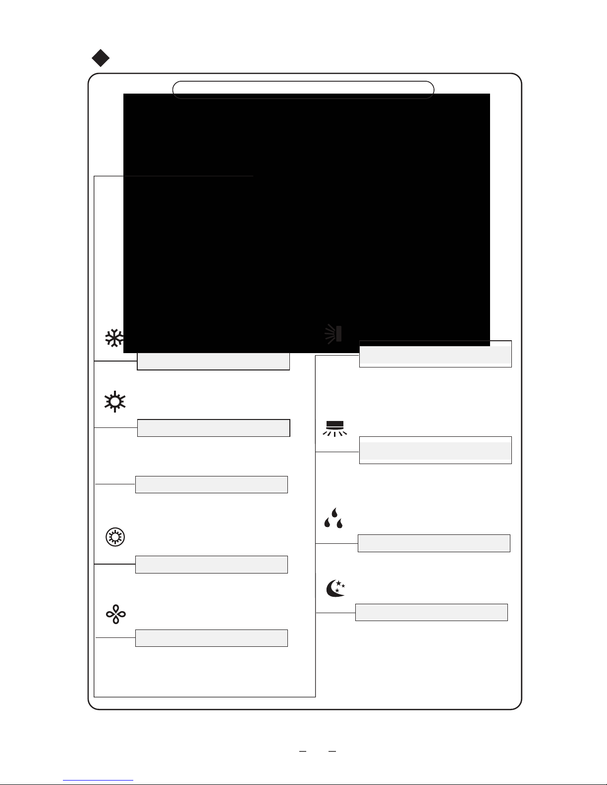
11
●
Η λειτουργία ύπνου εμφανίζεται και αυτή
η λειτουργία μπορεί να ρυθμιστεί μόνο
από το τηλεχειριστήριο.
Ένδειξη Sleep
●
Ένδειξη Κατακόρυφης Κίνησης
της Περσίδας
●
Ένδειξη Οριζόντιας Κίνησης
της Περσίδας
● Μειώστε την υγρασία και κρατήστε τη
θερμοκρασία του δωματίου αμετάβλητη.
Ένδειξη DRY
Ένδειξη Ταχύτητας
●
Η ταχύτητα μπορεί να ρυθμιστεί από
πλήκτρο ή από το τηλεχειριστήριο:
AUTO, LOW, MED, HIGH, ή TURBO
και θα εμφανιστεί αντίστοιχα στην οθόνη.
Ένδειξη E-HEATER
●
Ένδειξη X-FAN
●
●
●
Ένδειξη Λειτουργίας Ψύξης
●
Εμφανίζεται η λειτουργία ψύξης.
Ένδειξη Λειτουργίας Θέρμανσης
●
Εμφανίζεται η λειτουργία θέρμανσης.
Όταν εμφανίζεται αυτή η λέξη, η
λειτουργία του E-HEATER
ενεργοποιείται.
Όταν εμφανίζεται αυτή η λέξη, η
λειτουργία του X-FAN ενεργοποιείται.
空调器功能键空调器功能键
Πλήκτρα Λειτουργίας και Οθόνη του Κλιματιστικού
Πλήκτρα Λειτουργιών του Κλιματιστικού
Ονομασίες και Λειτουργίες κάθε Πλήκτρου του Κλιματιστικού
ΨΥΞΗ
ΘΕΡΜΑΝΣΗ
ΤΑΧΥΤΗΤΑ
E-HEATER
X-FAN
SWING
Η κατάσταση οριζόντιας κίνησης της
περσίδας εμφανίζεται.
Μόνο δύο καταστάσεις: on που σημαίνει
πως είναι ενεργοποιημένο ενώ off που
σημαίνει ότι είναι απενεργοποιήμενο.
Η κατάσταση κατακόρυφης κίνησης της
περσίδας εμφανίζεται.
Μόνο δύο καταστάσεις: on που σημαίνει
ότι η μονάδα είναι ενεργοποιημένη ενώ off
που σημαίνει ότι η μονάδα είναι
απενεργοποιημένη.
DRY
SLEEP
SWING

12
FAN
AUTO
OPER
HEALTH
AIR
FILTER
TURBO
ON/OFF
X-FAN
HOUR
HUMIDITY
ON/OFF
MODE
FAN
X-FAN
TURBO
TEMP
TIMER
SLEEP
LIGHT
2
11
7
10
13
9
43
12
8
6
14
5
1
Πατήστε για να επιλέξετε λειτουργία
ON/OFF
MODE
+
-
Πατήστε για να ξεκινήσετε ή να
σταματήσετε τη λειτουργία.
(AUTO/COOL/DRY/FAN/HEAT).
: Πατήστε το να αυξήσετε
θερμοκρασία.
: Πατήστε το να μειώσετε
θερμοκρασία.
FA
HEALTH SAVE
N
Πατήστε το να ρυθμίσετε πάνω & κάτω τη γωνία
της περσίδας.
Πατήστε το να ανάψετε/ σβήσετε
το φωτισμό.
TIMER
X-FAN (σελίδα 15)
(σελίδα 15)
TEMP(σελίδα 15)
TURBO(σελίδα 15)
SLEEP(σελίδα 16)
LIGHT
Πατήστε το να ρυθμίσετε ταχύτητα
ανεμιστήρα.
Πατήστε το να ρυθμίσετε τον χρονοδιακότπη ON/OFF.
.
1
2
Πατήστε το να ενεργοποιήσετε ή απενεργοποιήσετε
τη λειτουργία health.
7
4
3
5
6
Πατήστε το να ρυθμίσετε αριστερά ή δεξιά τη περσίδα.
8
11
9
10
12
13
14
Λειτουργία Ασύρματου Τηλεχειριστηρίου

Λειτουργία Ασύρματου Τηλεχειριστηρίου
Εικονίδιο LOCK:
Εικονίδιο MODE:
Εικονίδιο LIGHT:
Αν πατηθεί το εικονίδιο MODE,
εμφανίζονται τα εικονίδια λειτουργίας
εμφανίζεται πατώντας τα
πλήκτρα "+" και το "-" ταυτόγχρονα.
Πατήστε τα ξανά να επαναφέρετε
την οθόνη.
εμφανίζεται πατώντας το
πλήκτρο LIGHT. Πατήστε ξανά το
πλήκτρο LIGHT να επαναφέρετε
την οθόνη.
εμφανίζεται πατώντας το
πλήκτρο SLEEP. Πατήστε ξανά να
επαναφέρετε την οθόνη.
Πατώντας το πλήκτρο TEMP.
(ρυθμισμένη θερμοκρασία),
(θερμοκρασία χώρου),
(εξωτερική θερμοκρασία)
και κενό, εμφανίζονται κυκλικά.
εμφανίζεται πατώντας το
πλήκτρο αριστερής και δεξιάς
κίνησης της περσίδας. Πατήστε
ξανά να επαναφέρετε την οθόνη.
εμφανίζεται πατώντας το πλήκτρο
κίνησης περσίδας άνω και κάτω.
Πατήστε ξανά το πλήκτρο να
επαναφέρετε την οθόνη.
,)OTUA( ,)LOOC (
(DRY), (FAN) ή
(ΗΕΑΤ μόνο για μοντέλα θέρμανσης).
15
20
Εικονίδιο άνω & κάτω κίνησης
περσίδων:
Εικονίδιο αριστερής & δεξιάς
κίνησης περσίδων:
Αφότου πατήσετε το πλήκτρο
TIMER, θα αναβοσβήσουν τα
ON ή OFF. Αυτή η περιοχή
δείχνει τη ρυθμισμένη θερμοκρασία.
Ένδειξη SET TIME:
21
Αυτή η περιοχή θα δείξει τη
ρυθμισμένη θερμοκρασία. Σε
λειτουργία SAVE, "SE" θα εμφανιστεί. Κατά τη λειτουργία
αποπάγωσης, Η1 θα εμφανιστεί.
Ένδειξη DIGITAL:
23
Πατήστε το πλήκτρο FAN να
επιλέξετε την επιθυμητή ρύθμιση
ταχύτητας ανεμιστήρα (AUTO,
Low-Med-High). Η επιλογή θα
εμφανιστεί στο LCD παράθυρο,
εκτός από τη ταχύτητα ανεμιστήρα
AUTO.
ΈνδειξηFAN SPEED:
24
16
17
Εικονίδιο SLEEP:
18
Εικονίδιο TEMP:
19
FAN
AUTO
OPER
HEALTH
AIR
FILTER
TURBO
ON/OFF
X-FAN
HOUR
HUMIDITY
191520
18
16
17
21
22
23
24
13
22
19

Περιγραφή Τηλεχειριστηρίου
ON/OFF
Σημείωση: Αυτό είναι τηλεχειριστήριο γενικής χρήσης, μπορεί να χρησιμοποιηθεί για
κλιματιστικά που παρουσιάζουν δυσλειτουργίες. Για ορισμένες λειτουργίες, που το
μοντέλο δεν έχει, αν πατήσετε το αντίστοιχο πλήκτρο στο τηλεχειριστήριο, το
κλιματιστικό θα συνεχίσει να λειτουργεί χωρίς κάποια αλλαγή.
:
MODE :
+ :
FAN:
1
2
4
3
5
Λειτουργία Ασύρματου Τηλεχειριστηρίου
-14-
Πατήστε αυτό το πλήκτρο να ενεργοποιήσετε τη μονάδα. Πατήστε το πλήκτρο ξανά να
απενεργοποιήσετε τη μονάδα.
Κάθε φορά που πατάτε αυτό το πλήκτρο, μια λειτουργία επιλέγεται με την εξής σειρά
ΑUTO, COOL, DRY, FAN και HEAT * όπως το ακόλουθο:
AUTO
COOL
DRY
FAN HE
AT
*
*Σημείωση: Μόνο για μοντέλα με λειτουργία θέρμανσης.
Αφότου ενεργοποιήσετε, AUTO λειτουργία έχει προεπιλεγεί. Σε λειτουργία AUTO,
η ρυθμισμένη θερμοκρασία δεν θα εμφανίζεται στην LCD οθόνη και η μονάδα
αυτόματα θα επιλέξει την κατάλληλη λειτουργία σύμφωνα με τη θερμοκρασία
δωματίου για άνετες συνθήκες χώρου.
Πατήστε αυτό το πλήκτρο να μειώσετε τη ρυθμισμένη θερμοκρασία. Κρατήστε το για
πάνω από 2 δευτερόλεπτα ώστε γρήγορα να μειώσετε τη ρυθμισμένη θερμοκρασία.
Σε AUTO λειτουργία, η ρυθμισμένη θερμοκρασία δεν προσαρμόζεται.
Πατήστε αυτό το πλήκτρο να αυξήσετε τη θερμοκρασία. Κρατήστε το για πάνω από 2
δευτερόλεπτα ώστε να αυξήσετε γρήγορα τη ρυθμισμένη θερμοκρασία. Σε λειτουργία
AUTO η θερμοκρασία δεν προσαρμόζεται.
Αυτό το πλήκτρο χρησιμοποιείται για ρύθμιση της ταχύτητας του ανεμιστήρα σε σειρά
όπως AUTO, , σε και ξανά AUTO.
Auto
Χαμηλή
ταχύτητα
Μέση
ταχύτητα
Υψηλή
ταχύτητα
:
6
Πατήστε το πλήκτρο να εκκινήσετε ή να σταματήσετε την άνω & κάτω λειτουργία
των περσίδων. Το τηλεχειριστήριο έχει προεπιλογή την απλή κίνηση περσίδων.
Πατήστε το πλήκτρο + και την ίδια στιγμή το πλήκτρο OFF στη μονάδα να
λειτουργήσετε μεταξύ απλής κίνησης και στατικής. θα αναβοσβήσει για 2
δευτερόλεπτα.
Αν η μονάδα απενεργοποιηθεί κατά τη διάρκεια κίνησης της περσίδας, η περσίδα
θα σταματήσει σε εκείνη τη θέση.
●
●
●
●
Σε στατική κίνηση, πατήστε το πλήκτρο και θα αλλάξει η γωνία της περσίδας
άνω & κάτω όπως παρακάτω:

Πατήστε το πλήκτρο να εκκινήσετε ή σταματήσετε την αριστερή & δεξιά λειτουργία
κίνησης της περσίδας. Το τηλεχειριστήριο προεπιλέγει την απλή λειτουργία κίνησης.
Πατήστε το πλήκτρο + και ταυτόγχρονα στη μονάδα OFF να λειτουργήσετε τη
μονάδα μεταξύ απλής κίνησης και στατικής κίνησης; θα αναβοσβήσει για 2
δευτερόλεπτα.
Σε λειτουργία στατικής κίνησης, πατήστε το πλήκτρο , να κινηθεί η περσίδα
αριστερά & δεξιά όπως παρακάτω:
10
TEMP:
Πατώντας αυτό το πλήκτρο, επιλέγετε την εμφάνιση της ρυθμισμένης εσωτερικής
θερμοκρασίας ή της εσωτερικής θερμοκρασίας χώρου. Όταν η εσωτερική μονάδα αρχικά
συνδεθεί στο ρεύμα θα εμφανίσει την ρυθμισμένη θερμοκρασία, αν η ένδειξη κατάστασης
θερμοκρασίας αλλάξει σε άλλη κατάσταση σε , εμφανίζει την θερμοκρασία χώρου,
5 δευτερόλεπτα αργότερα ή μέσα σε 5 δευτερόλεπτα, δέχεται άλλο σήμα από το
τηλεχειριστήριο το οποίο θα εμφανίσει την ρυθμισμένη θερμοκρασία. Αν ο χρήστης δεν
έχει ρυθμίσει την ένδειξη αλλαγής κατάστασης της θερμοκρασίας, η οθόνη θα εμφανίζει
τη ρυθμισμένη θερμοκρασία.
HEALTH SAVE:
Πατήστε το μέρος του πλήκτρου HEALTH ώστε να ενεργοποιήσετε ή απενεργοποιήσετε
τη λειτουργία HEALTH. Πατήστε το μέρος του πλήκτρου SAVE και στην οθόνη θα
αναγραφεί το ,ξανά να ακυρώσετε τη λειτουργία SAVE. Κατά τη διάρκεια της
SAVE λειτουργίας, η θερμοκρασία και η ταχύτητα του αέρα δεν προσαρμόζονται.
7
Πατήστε το πλήκτρο TIMER στη μονάδα ON να ρυθμίσετε TIMER OFF; HOUR OFF
αναβοσβήνει. Πατήστε το πλήκτρο TIMER στη μονάδα OFF να ρυθμίσετε TIMER ON;
HOUR ON αναβοσβήνει. Σε αυτή τη περίπτωση, πατήστε το πλήκτρο + ή - να αλλάξετε
τη ρύθμιση χρονοδιακόπτη. Κρατήστε πατημένο ώστε να αλλάξει γρήγορα η ρύθμιση
κατάστασης (ρύθμιση χρονοδιακόπτη για 0.5-24 ώρες). Πατήστε το πλήκτρο TIMER
ξανά να επιβεβαιώσετε τη ρύθμιση; HOUR ON/OFF σταματάει να αναβοσβήνει. Αν δεν
υπάρχει λειτουργία από το πλήκτρο για τα επόμενα 5 δευτερόλεπτα ενώ αναβοσβήνει
το HOUR ON/OFF, TIMER ρυθμίσεις θα ακυρωθούν.
TIMER:
11
X-FAN:
TURBO:
9
12
15
:
8
Πατώντας το πλήκτρο X-FAN σε Ψύξη ή Αφύγρανση, το εικονίδιο X-FAN θα εμφανιστεί
και ο εσωτερικός ανεμιστήρας θα συνεχίσει να λειτουργεί για 10 λεπτά ώστε να πραγματοποιήσει αφύγρανση στην εσωτερική μονάδα παρόλο που θα έχετε απενεργοποιήσει
τη μονάδα. Μετά την ενεργοποίηση, X-FAN OFF προεπιλέγεται. X-FAN δεν διατείθεται
σε AUTO, FAN και HEAT λειτουργία.
Πατήστε αυτό το πλήκτρο να ενεργοποιήσετε ή να απενεργοποιήσετε τη λειτουργία Turbo
ώστε η μονάδα να φτάσει την προεπιλεγμένη θερμοκρασία σε γρήγορο διάστημα.
Σε λειτουργία ΨΥΞΗΣ, η μονάδα θα βγάλει δυνατό κρύο αέρα σε φοβερά υψηλή ταχύτητα
ανεμιστήρα. Σε λειτουργία ΘΕΡΜΑΝΣΗΣ, η μονάδα θα βγάλει δυνατό αέρα θέρμανσης
σε φοβερά υψηλά ταχύτητα ανεμιστήρα.
(Αυτή η λειτουργία δεν ενδείκνυται για ορισμένα μοντέλα).
Λειτουργία Ασύρματου Τηλεχειριστηρίου
●
●
●
Αν η μονάδα απενεργοποιηθεί κατά τη λειτουργία κίνησης της περσίδας, η περσίδα θα
σταματήσει στη θέση εκείνης της στιγμής.
●

Συνδιασμός του πλήκτρου "+" και "-".
Για το κλείδωμα πατήστε τα πλήκτρα "+" και "-" ταυτόγχρονα να κλειδώσετε ή
ξεκλειδώσετε το πληκτρολόγιο. Αν το τηλεχειριστήριο είναι κλειδωμένο, θα
εμφανιστεί. Σε αυτή τη περίπτωση, πατώντας οποιοδήποτε πλήκτρο, αναβοσβήνει
3 φορές.
SLEEP :
LIGHT:
13
14
Πατήστε αυτό το πλήκτρο για λειτουργία SLEEP. Πατήστε το ξανά να ακυρώσετε αυτή
τη λειτουργία. Αυτή η λειτουργία ενδείκνυται για ΨΥΞΗ, ΘΕΡΜΑΝΣΗ (μόνο για
ορισμένα μοντέλα η λειτουργία θέρμανσης) ή ΑΦΥΓΡΑΝΣΗ ώστε να διατηρήσετε
άνετη θερμοκρασία για εσάς.
Πατήστε το πλήκτρο LIGHT στην οθόνη και πατήστε ξανά να απενεργοποιήσετε τη
λυχνία. Αν είναι αναμμένη η λυχνία, εμφανίζεται. Αν σβήσει η λυχνία, εξαφανίζεται.
16
★
1. Aφαιρέστε το κάλυμμα από το πίσω μέρος του τηλεχειριστηρίου.
(όπως φαίνεται στο σχήμα)
2. Αφαιρέστε τις παλιές μπαταρίες
3. Βάλτε δυο νέες ΑΑΑ1.5V μπαταρίες ξηρού τύπου και προσέξτε τη
πολικότητα.
4. Επανατοποθετήστε το κάλυμμα
Σκαρίφιμα για την
αντικατάσταση των
μπαταριών
3
2
Λειτουργία Ασύρματου Τηλεχειριστηρίου
15
Συνδιασμός του πλήκτρου "MODE" και "-". Για την εναλλαγή μεταξύ ºF και ºC.
Στη μονάδα OFF, πατήστε το πλήκτρο "MODE" και "-" ταυτόγχρονα να αλλάξετε
μεταξύ ºC και ºF.
16
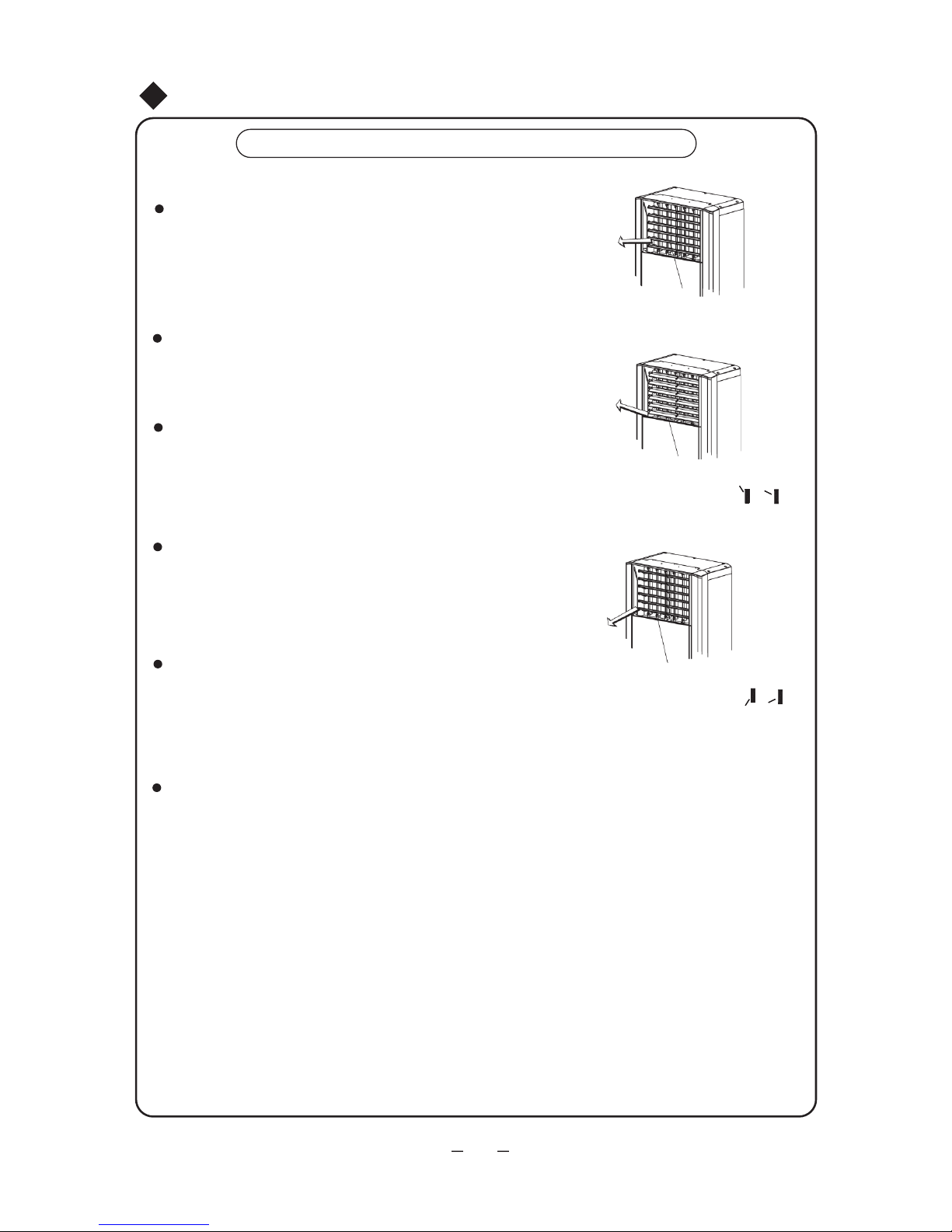
Κίνηση περσίδων πάνω και κάτω
Σημειώσεις:
Αν λειτουργεί ο εσωτερικός ανεμιστήρας, πατήστε το πλήκτρο στο
τηλεχειριστήριο άνω & κάτω κίνησης της περσίδας. Ανατρέξτε στις οδηγίες
Τηλεχειριστηρίου για λειτουργία κίνησης της περσίδας.
Επιλέξτε άνω & κάτω κίνηση της περσίδας στην οθόνη και πατήστε το
πλήκτρο ή να εκκινήσετε ή να σταματήσετε τη κίνηση. Πατήστε το
μια φορά να ξεκινήσει και άλλη μια να σταματήσει.
▼ ▲
Αν επιλεχθεί η διακοπή της κίνησης, οι χαρακτήρες και τα εικονίδια για
την άνω & κάτω κίνηση θα εξαφανιστούν. Όταν άλλες καταστάσεις
επιλεχθούν, χαρακτήρες και εικονίδια για την άνω & κάτω κίνηση θα
εμφανιστούν ξανά.
Προσαρμογή κίνησης Περσίδων
ή
Εικ.3
17
Περσίδες σε ευθεία θέση
Περσίδες σε θέση προς τα πάνω
(Μπορεί να γίνει ρύθμιση σε )
ή
(Μπορεί να γίνει ρύθμιση σε )
Εικ.4
Περσίδες σε θέση προς τα κάτω
Εικ.5
Πιέζοντας το πλήκτρο κίνησης περσίδων πάνω και κάτω (οριζόντια) στην
οθόνη ή στο ασύρματο τηλεχιεριστήριο, επιλέγετε την κίνηση των περσίδων
πάνω και κάτω. Δίνεται εντολή στο αντίστοιχο μοτέρ της μονάδας και
μπορείτε να επιλέξετε είτε συνεχόμενη κίνηση των περσίδων πάνω και κάτω
είτε να σταθεροποιηθούν σε κάποια συγκεκριμένη γωνία.
Κατά την ψύξη ή αφύγρανση, επιλέξτε οι περσίδες να είναι είτε σε ευθεία
θέση ή προς τα πάνω (όπως φαίνεται στην εικόνα 4)
Κατά τη θέρμανση, επιλέξτε η θέση των περσίδων να είναι προς τα κάτω.
(όπως φαίνεται στην εικόνα 5)
Κατά την ενεργοποίηση, μπορείτε να επιλέξτε η θέση των περσίδων να
είναι προς τα κάτω, έτσι ώστε να μειωθεί γρήγορα η θερμοκρασία του
χώρου. Όμως αυτή τη θέση δεν θα πρέπει να την επιλέξετε για πολύ
ώρα, έτσι ώστε να διατηρείται ο καλός εξαερισμός του χώρου.

Κίνηση Δεξιά & Αριστερή
Η αριστερή & δεξιά κίνηση της περσίδας μπορεί να επιλεχθεί να
ελέγχει την εκκίνηση ή διακοπή ή τη δεξιόστροφη ή αριστερόστροφη
κίνηση πατώντας το αριστερό & δεξί πλήκτρο στο τηλεχειριστήριο ή
το πλήκτρο FUNC στην οθόνη, ώστε η περσίδα να κινηθεί αριστερά
ή δεξιά ή να σταματήσει σε συγκεκριμένη γωνία.
Αν η εσωτερική μονάδα λειτουργεί, πατήστε το αριστερό & δεξί
πλήκτρο στο τηλεχειριστήριο. Ανατρέξτε στις οδηγίες χρήσης
τηλεχειριστηρίου για τη λειτουργία κίνησης της περσίδας.
Επιλέξτε το αριστερό & δεξί πλήκτρο κίνησης της περσίδας στην
οθόνη ώστε να το ρυθμίσετε και πατήστε το πλήκτρο ή ώστε
να εκκινήσετε ή σταματήσετε τη κίνηση. Πατήστε το μια φο
ρά για
εκκίνηση και ξανά μια φορά για διακοπή.
▼ ▲
Αν επιλεχθεί η διακοπή της κίνησης, οι χαρακτήρες και τα εικονίδια για την
άνω & κάτω κίνηση θα εξαφανιστούν. Όταν επιλεχθεί άλλη κατάσταση
λειτουργίας, οι χαρακτήρες και τα εικονίδια για την άνω & κάτω κίνηση θα
ξανά εμφανιστούν.
Εικ.6
Πλήκτρο κίνησης περσίδας
αριστερά & δεξιά
Πλήκτρο κίνησης περσίδας
πάνω & κάτω
Προσαρμογή της περσίδας
18

Λειτουργία και Παρατηρήσεις για την Συρόμενη Πόρτα
1. Όταν ενεργοποιηθεί η εσωτερική μονάδα, η συρόμενη πόρτα
αυτόματα θα κινηθεί προς τα κάτω στην εσωτερική μεριά του
μπροστινού πάνελ.
2. Αν η συρόμενη πόρτα ανοίξει τελείως, η άνω & κάτω κίνηση
της περσίδας θα αρχίσει και θα ξεκινήσει να λειτουργεί ο
ανεμιστήρας.
Κατά την εκκίνηση της λειτουργίας
Στο πέρας της λειτουργίας
1. Όταν απενεργοποιηθεί η εσωτερική μονάδα, θα κινηθεί η
περσίδα άνω & κάτω σε συγκεκριμένο μέρος.
2. Αν σταματήσει η άνω & κάτω κίνηση της περσίδας, η
συρόμενη πόρτα αυτόματα θα ανασηκωθεί να κλείσει την
εξαγωγή του αέρα.
Παρατήρηση:
1. Μην προσαρμόζετε χειροκίνητα την συρόμενη πόρτα.
2. Η συρόμενη πόρτα θα διατηρήσει τη θέση της όταν υπάρξει διακοπή ρεύματος.
Αυτόματα θα κλείσει μόλις επανέλθει το ρεύμα.
3. Αν εμφανιστεί στην οθόνη το FC, θα υπάρξουν δυσλειτουργίες με τη συρόμενη
πόρτα. Θα επανέλθει μετά από επανεκκίνηση της μονάδας. Αν ξαναεμφανιστεί
το FC, η μονάδα χρίζει επισκευής.
4. Αν η μονάδα λειτουργείται σε λειτουργία ψύξης για αρκετό καιρό, μπορεί να
υπάρξει διαρροή νερού στη συρόμενη πόρτα, το οποίο είναι φυσιολογικό.
Εισαγωγή για Ειδικές Λειτουργίες
19

①
②
③
Καθαρισμός και φροντίδα
Προσοχή
1.Διακόψτε την παροχή ρεύματος πριν από τον καθαρισμό, μπορεί να προκληθεί ηλεκτροπληξία.
2.Μην ψεκάζετε με νερό την εσωτερική και την εξωτερική μονάδα, διότι μπορεί να προκληθεί
ηλεκτροπληξία.
3.Μην χρησιμοποιείτε οξέα και αλκαλικά διαλύματα για τον καθαρισμό. (Χρησιμοποιείτε μαλακό πανί
για τον καθαρισμό, ή μαλακό πανί ελαφρώς βρεγμένο με νερό ή καθαριστικό)
Καθαρισμός της μονάδας
Διακόψτε την παροχή ρεύματος πριν από
τον καθαρισμό.
Χρησιμοποιείτε μαλακό πανί για τον καθαρισμό
του πλαισίου.
Μην ψεκάζετε με νερό την εσωτερική μονάδα.
Όταν η μονάδα σταματήσει να λειτουργεί, τότε μπορείτε να την
απενεργοποιήσετε
Αν το πλαίσιο είναι πολύ βρώμικο, βρέξτε το πανί με ζεστό νερό
θερμοκρασίας κάτω των 40 °C, στεγνώστε το και στη συνέχεια τρίψτε
το πλαίσιο για να το καθαρίσετε
(Όπως φαίνεται στην εικόνα7)
Μπορεί να προκαλέσει βλάβη στην οθόνη και την πλακέτα
της μονάδας (Όπως φαίνεται στην εικόνα7)
Εικ.7
Στεγνώστε το πανί
πριν τον καθαρισμό
Καθαρίστε το φίλτρο αέρα (μία φορά κάθε 2 βδομάδες)
Εικ.8
Αποσυναρμολόγηση του φίλτρου αέρα
Όπως φαίνεται στο Σχ. 8, αφαιρέστε τη διακοσμητική λωρίδα
στη θέση (1) και ξεβιδώστε τις βίδες. Αφότου ανοίξετε το
γυάλινο πάνελ ξεβιδώστε τις βίδες που συγκρατούν το φίλτρο
αέρα. Τέλος, αφαιρέστε το φίλτρο αέρα με την κατεύθυνση
που δείχνει το βέλος.
Φίλτρο
Σκουπίζοντας το ελαφρά ή χρησιμοποιήστε ηλεκτρική σκούπα.
Αν έχει συσσωρευτεί υπερβολική σκόνη στο φίλτρο,χρησιμοποιήστε
νερό με λίγο ουδέτερο απορρυπαντικό για να το καθαρίσετε και στ
η συνέχεια
πλύνετέ το με νερό βρύσης. Μετά τον καθαρισμό στεγνώστε το και
επανατοποθετήστε το.
(Όπως φαίνεται στην εικόνα 8)
①
②
Παρατήρηση: Μην στεγνώνετε το φίλτρο εκθέτοντάς το σε
απευθείας ηλιακή ακτινοβολία ή δίπλα σε πηγή θερμότητας
αλλιώς μπορεί να παραμορφωθεί.
20
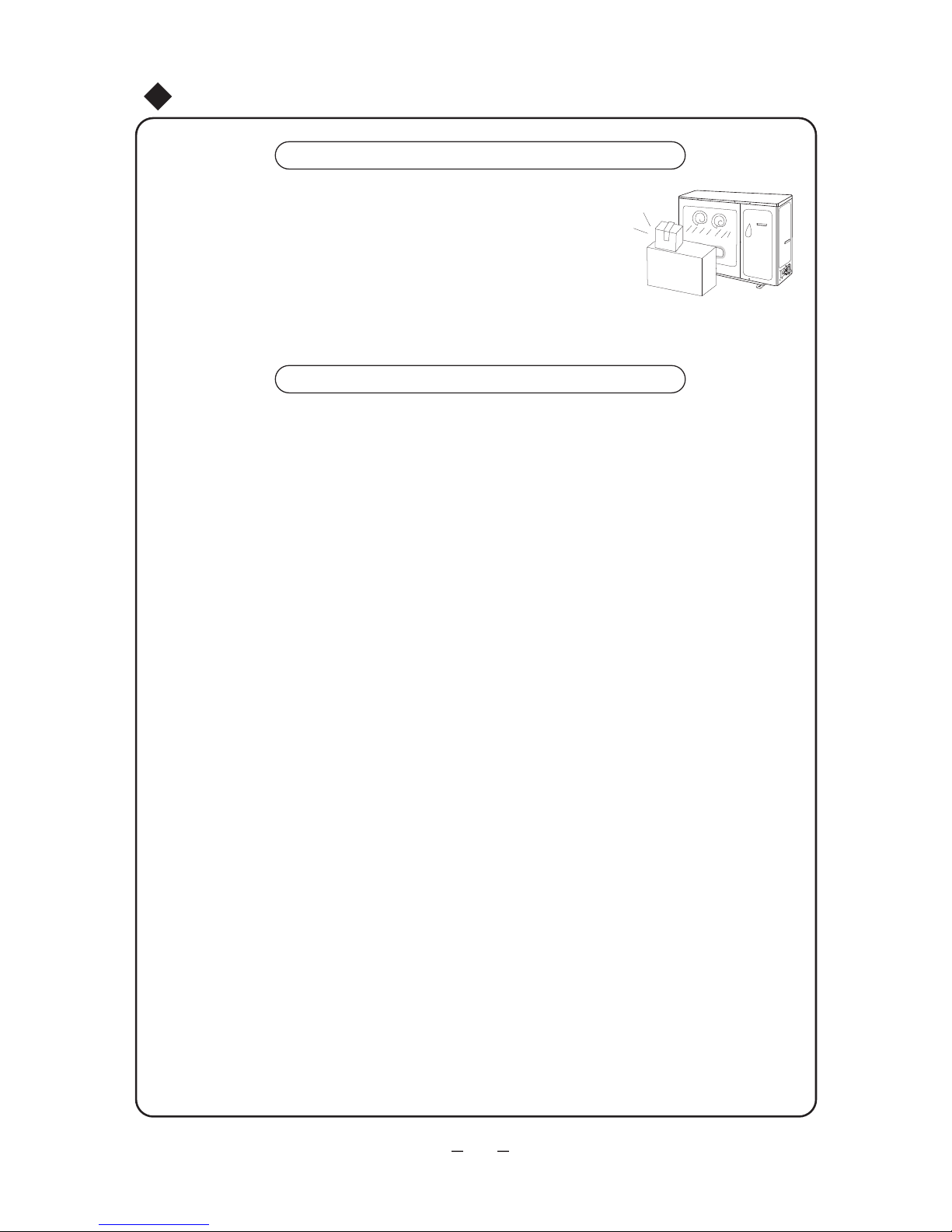
Έλεγχος πριν τη χρήση
Συντήρηση μετά τη χρήση
Βεβαιωθείτε πως δεν υπάρχουν εμπόδια στις εισόδους και εξόδους του αέρα
Βεβαιωθείτε πως έχει συνδεθεί σωστά η γείωση.
Ελέγξτε αν οι μπαταρίες του τηλεχειριστηρίου έχουν αντικατασταθεί.
Βεβαιωθείτε εάν η βάση της εξωτερικής μονάδας είναι σε καλή
κατάσταση. Εάν όχι, επικοινωνήστε με εξουσιοδοτημένο συνεργείο.
Καθαρίστε τα φίλτρα , την εσωτερική και εξωτερική μονάδα.
Καθαρίστε την εξωτερική μονάδα και απομακρύντε τυχόν εμπόδια.
Ξαναβάψτε τυχόν σκουριασμένα μέρη στην εξωτερική μονάδα, έτσι ώστε
να αποφευχθεί η εξάπλωση.
Απενεργοποιήστε τη μονάδα.
①
②
③
④
①
②
③
④
Καθαρισμός και φροντίδα
21

22
Αντιμετώπιση προβλημάτων
ΠΡΟΣΟΧΗ
Μην προσπαθήσετε να επισκευάσετε μόνοι σας τη μονάδα, μπορεί να προκληθεί
ηλεκτροπληξία ή πυρκαγιά. Ελέγξτε τα παρακάτω πριν ζητήσετε βοήθεια, μπορεί
να κερδίσετε χρόνο και χρήματα.
Σύμπτωμα
Αντιμετώπιση προβλήματος
Για την προστασία της κλιματιστικής μονάδας όταν
πραγματοποιείται επανεκκίνηση αμέσως μετά από
μια διακοπή λειτουργίας, η μονάδα ελέγχου με
μικροϋπολογιστή καθυστερεί την έναρξη της
λειτουργίας για περίπου 3 λεπτά
Η κλιματιστική μονάδα δεν λειτουργεί όταν
πραγματοποιείται επανεκκίνηση αμέσως
μετά από μια διακοπή λειτουργίας.
Waiting
Από την κλιματιστική μονάδα αναδύεται
δυσάρεστη οσμή κατά την εκκίνηση της
λειτουργίας της.
Η κλιματιστική μονάδα από μόνη της δεν έχει
δυσάρεστη οσμή. Αν υπάρχει δυσάρεστη οσμή έχει
απορροφηθεί από το περιβάλλον.
Λύση: Καθαρίστε το φίλτρο του αέρα.
Αν εξακολουθεί να υπάρχει πρόβλημα, η
κλιματιστική μονάδα θα πρέπει να καθαριστεί
(Παρακαλούμε επικοινωνήστε με το
Εξουσιοδοτημένο Κέντρο Τεχνικής Υποστήριξης)
Κατά τη λειτουργία της κλιματιστικής
μονάδας ακούγεται μερικές φορές ένας
θόρυβος σαν "νερό που κυλάει".
Κατά την εκκίνηση της κλιματιστικής μονάδας, κατά
την εκκίνηση ή τη διακοπή της λειτουργίας του
συμπιεστή, ή κατά τη διακοπή της λειτουργίας της
κλιματιστικής μονάδας, κάποιες φορές μπορεί να
ακούγεται ένας θόρυβος σαν νερό που βράζει ή
επαναλαμβανόμενος χτύπος. Πρόκειται για θόρυβο
που προκαλείται από τη ροή του ψυκτικού υγρού
και όχι για κάποιο σφάλμα.
Κάποιες φορές, όταν η κλιματιστική
μονάδα βρίσκεται σε λειτουργία ψύξης από
την έξοδο αέρα βγαίνει ένα λεπτό στρώμα
ομίχλης.
Αυτό μπορεί να συμβαίνει όταν η θερμοκρασία και
η υγρασία του εσωτερικού χώρου είναι υψηλές.
Αυτό οφείλεται στο γεγονός ότι ο αέρας του
εσωτερικού χώρου ψύχεται γρήγορα. Μετά από
λίγο, η ομίχλη εξαφανίζεται καθώς η θερμοκρασία
και η υγρασία του εσωτερικού χώρου μειώνονται.
Όταν η κλιματιστική μονάδα ξεκινά ή
σταματά κάποιες φορές ακούγεται ένα
μικρό τρίξιμο.
Πρόκειται για τους τριγμούς που
προκαλούνται από τη διαστολή του
πλαισίου ή των άλλων μερών λόγω της
αλλαγής θερμοκρασίας.

23
Αντιμετώπιση προβλημάτων
Σύμπτωμα
Αντιμετώπιση προβλήματος
Η μονάδα δεν λειτουργεί
• Μήπως έχει διακοπεί η τροφοδοσία; •Μήπως το
βύσμα του ρεύματος έχει βγει από την πρίζα;
• Ο ασφαλειοδιακόπτης του κυκλώματος έχει
απενεργοποιηθεί;
• Η τάση είναι υψηλότερη ή χαμηλότερη; (Ελέγχεται
από επαγγελματία τεχνικό)
•
Χρησιμοποιείται σωστά το timer;
Break off
Η απόδοση ψύξης (θέρμανσης) δεν είναι
ικανοποιητική.
Το ασύρματο τηλεχειριστήριο δεν ανταποκρίνεται
Αν υπάρχει διαρροή νερού στο δωμάτιο
Αν υπάρχει διαρροή νερού στην εξωτερική
μονάδα
Η εσωτερική μονάδα κάνει θόρυβο.
• Όταν το κλιματιστικό είναι σε λειτουργία Ψύξης,
η σωλήνα και η σύνδεση της σωλήνας θα παρουσιάσουν σταγονίδια λόγω συμπύκνωσης του νερού.
• Κατά τη λειτουργία Θέρμανσης ή αποπάγωσης,
θα υπάρχει υπερχείλιση του νερού.
• Το νερό στον εναλλάκτη μπορεί να προκαλέσει
σταγονίδια κατά τη λειτουργία θέρμανσης.
• Η ρύθμιση της θερμοκρασίας είναι η κατάλληλη;
• Μήπως παρεμποδίζονται οι αεραγωγοί εισόδου
και εξόδου;
• Μήπως υπάρχει υπερβολική συσσωρευμένη
σκόνη και παρεμποδίζεται το φίλτρο;
•Τα παράθυρα και οι πόρτες είναι κλειστά;
•Μήπως η ταχύτητα του ανεμιστήρα είναι
ρυθμισμένη στο low (χαμηλή ταχύτητα);
• Μήπως υπάρχουν πηγές θερμότητας μέσα στο
δωμάτιο;
•Γίνονται συχνές ή μη φυσιολογικές αλλαγές
λειτουργιών στη μονάδα και περιστασιακά το
χειριστήριο δεν λειτουργεί. Σε αυτή την περίπτωση
θα πρέπει να αποσυνδέσετε το βύσμα και να το
επανασυνδέσετε.
• Βρίσκεται εντός εμβέλειας λήψης; Ή πιθανώς
παρεμποδίζεται; Ελέγξτε την τάση στο εσωτερικό
του ασύρματου τηλεχειριστηρίου για να δείτε αν είναι
φορτισμένες οι μπαταρίες, διαφορετικά
αντικαταστήστε τις.
• Ελέγξτε αν έχει φθαρεί το ασύρματο τηλεχειριστήριο.
• Η υγρασία του αέρα είναι υψηλή.
• υπερχείλισε η λεκάνη συμπυκνωμάτων.
• Η σύνδεση του αγωγού αποστράγγισης της
εσωτερικής μονάδας έχει χαλαρώσει.
• Πρόκειται για τον ήχο του ρελέ του ανεμιστήρα ή του
συμπιεστή που ανοίγει και κλείνει.
• Όταν ξεκινά ή διακόπτεται η αποπάγωση, ακούγεται
ένας ήχος. Οφείλεται στο ψυκτικό υγρό που κυλάει
προς την αντίθετη κατεύθυνση.

H1: Αποπάγωση • Είναι φυσιολογικό
24
Η λυχνία αναβοσβήνει και στην οθόνη εμφανίζεται E1
Η λυχνία αναβοσβήνει και στην οθόνη εμφανίζεται E3
Η λυχνία αναβοσβήνει και στην οθόνη εμφανίζεται E4
Η λυχνία αναβοσβήνει και στην οθόνη εμφανίζεται E5
Η λυχνία αναβοσβήνει και στην οθόνη εμφανίζεται F1
Η λυχνία αναβοσβήνει και στην οθόνη εμφανίζεται F2
Η λυχνία αναβοσβήνει και στην οθόνη εμφανίζεται F3
Η λυχνία αναβοσβήνει και στην οθόνη εμφανίζεται F4
Η λυχνία αναβοσβήνει και στην οθόνη εμφανίζεται F5
• E1: Προστασία υψηλής πίεσης.
• E3: Προστασία χαμηλής πίεσης.
• E4: Προστασία υψηλής θερμοκρασίας στην έξοδο του
συμπιεστή.
• E5: Προστασία υπερβολικής τάσης.
• F1: Βλάβη στον αισθητήρα εσωτερικής θερμοκρασίας.
• F2: Βλάβη στον αισθητήρα θερμοκρασίας στοιχείου.
• F3: Βλάβη στον αισθητήρα εξωτερικής θερμοκρασίας.
• F4: Βλάβη στον αισθητήρα θερμοκρασίας εξωτερικού
στοιχείου.
• F5: Βλάβη αισθητήρα στην έξοδο αέρα.
(HEAT),
,
2-5 )
(HEAT),
,
,
10
,
25
Oδηγίες εγκατάστασης - Eπισημάνσεις για την εγκατάσταση
Σημαντικές επισημάνσεις
1. Οι εργασίες εγκατάστασης της μονάδας πρέπει να διεξάγονται από καταρτισμένο
προσωπικό, σύμφωνα με τους τοπικούς κανονισμούς και με αυτό το εγχειρίδιο χρήσης.
2. Για την εγκατάσταση επικοινωνήστε με εξουσιοδοτημένο συνεργείο, σε αντίθετη
περίπτωση κάποια πιθανή βλάβη δεν θα μπορέσει να λυθεί.
3. Για την μεταφορά της μονάδας σε κάποιο άλλο σημείο, επικοινωνήστε με το
εξουσιοδοτημένο συνεργείο της περιοχής σας.
Θέση εγκατάστασης
Θέση εγκατάστασης τηε εξωτερικής μονάδας
Θέση εγκατάστασης της εσωτερικής μονάδας
Τυχόν εγκατάσταση στα ακόλουθα σημεία ενδέχεται να προκαλέσει δυσλειτουργία.
Αν δεν μπορείτε να αποφύγετε την εγκατάσταση σε αυτά, παρακαλούμε επικοινωνήστε με
το κέντρο τεχνικής υποστήριξης:
• Μέρη όπου εκπέμπεται έντονη θερμότητα, ατμοί, εύφλεκτα ή πτητικά αέρια
• Μέρη όπου παράγονται κύματα υψηλής συχνότητας από ραδιοφωνικές συσκευές,
συσκευές συγκόλλησης και ιατρικά μηχανήματα.
• Μέρη όπου υπάρχει αυξημένη συγκέντρωση αλάτων, όπως σε ακτές.
• Μέρη όπου ο αέρας περιέχει έλαια (λάδι μηχανής).
• Μέρη όπου παράγεται θειούχο αέριο, όπως σε ζώνες θερμών πηγών.
• Άλλα μέρη με ειδικές συνθήκες.
• Σε σημείο με τη λιγότερη δυνατή επίδραση από τον εξωτερικό αέρα.
• Σε σημείο όπου δεν παρεμποδίζεται η ελεύθερη ροή του αέρα μέσα και έξω από τη μονάδα.
• Σε σημείο όπου ο αγωγός ψυκτικού μέσου μπορεί εύκολα να οδηγηθεί προς τα έξω.
• Σε σημείο απ' όπου ο αέρας από τη μονάδα μπορεί να φτάσει σε κάθε γωνία του δωματίου.
• Σε σημείο όπου δεν υπάρχει υπερβολική υγρασία και όπου δεν μπορεί εύκολα να πέσει
λάδι επάνω στη μονάδα.
• Σε σημείο όπου δεν είναι πιθανόν να υπάρξει διαρροή ή εύφλεκτο αέριο.
• Επιλέξτε σταθερό και επίπεδο έδαφος.
• Αφήστε αρκετό χώρο για την εγκατάσταση και τις εργασίες συντήρησης.
Βεβαιωθείτε ότι η εγκατάσταση της εσωτερικής μονάδας συμφωνεί με τις απαιτήσεις
του διαγράμματος διαστάσεων εγκατάστασης.
1. Επιλέξτε ένα σημείο όπου ο θόρυβος και ο αέρας από τη μονάδα δεν ενοχλούν γείτονες, ζώα, φυτά.
2. Επιλέξτε ένα σημείο με επαρκή εξαερισμό.
3. Επιλέξτε ένα σημείο όπου δεν υπάρχουν εμπόδια τα οποία καλύπτουν τους αεραγωγούς εισόδου και
εξόδου.
4. Η θέση εγκατάστασης θα πρέπει να μπορεί να αντέξει το συνολικό βάρος και τις δονήσεις της
εξωτερικής μονάδας και να επιτρέπει την ασφαλή εγκατάσταση.
5. Επιλέξτε ένα ξηρό μέρος, αλλά χωρίς απευθείας έκθεση στο ηλιακό φως ή σε ισχυρούς ανέμους.
6. Βεβαιωθείτε ότι οι διαστάσεις εγκατάστασης της εξωτερικής μονάδας συμφωνούν με το διάγραμμα
διαστάσεων εγκατάστασης και ότι δεν παρεμποδίζονται οι εργασίες συντήρησης και επισκευής.
7. Η διαφορά ύψους για τη σύνδεση των σωλήνων πρέπει να είναι μέχρι 5 m και το μήκος σύνδεσης των
καλωδίων μέχρι 15 m.
8. Επιλέξτε ένα σημείο όπου δεν μπορούν να φτάσουν τα παιδιά.
9. Επιλέξτε ένα σημείο όπου δεν εμποδίζεται η διέλευση και δεν επηρεάζεται αισθητικά το τοπίο.

26
Ηλεκτρικό διάγραμμα
1. Εγκαταστήστε πρώτα τις καλωδιώσεις της εξωτερικής μονάδας και έπειτα της εσωτερικής.
Αφού ολοκληρώσετε την εγκατάσταση, μπορείτε να συνδέσετε τη μονάδα με την παροχή.
2. Ακολουθήστε τις παρακάτω οδηγίες του συγκεκριμένου εγχειρίδιου για την εγκατάσταση
της εσωτερικής μονάδας.
3. Η μονάδα μπορεί να αλλάξει χωρίς προειδοποίηση.
4. Παρακαλούμε διαβάστε προσεκτικά το εγχειρίδιο πριν την εγκατάσταση. Λόγω του ότι η
παροχή της μονάδας είναι μεγάλη, θα πρέπει το αντίστοιχο κύκλωμα να συμφωνεί με τα
παρακάτω:
α. Ο ασφαλειοδιακόπτης θα πρέπει να συμφωνεί με τις απαιτήσεις του κατασκευαστή.
β. Η διάμετρος του καλωδίου θα πρέπει να είναι 1.5 φορά μεγαλύτερη από το μέγιστο
ρέυμα της μονάδας.
γ. Η ασφάλεια θα πρέπει να είναι επαρκούς χωρητικότητας.
δ. Βεβαιωθείτε πως το κεντρικό και το ειδικό κύκλωμα είναι ξεχωριστά.
ε. Η ελάχιστη απόσταση ανάμεσα στη μονάδα και οποιαδήποτε ευφλέκτη επιφάνεια πρέπει
να είναι 1.5 m
ζ. Η γείωση θα πρέπει να είναι συνδεδεμένη
και στην εσωτερική και στην εξωτερική μονάδα.
Απαιτήσεις ασφαλείας
●
●
Σημείωση:
Δώστε προσοχή στις συνθήκες περιβάλλοντος (π.χ εξωτερική θερμοκρασία, ηλιοφάνεια,
βροχές κλπ).
Το παροχικό καλώδιο σύνδεσης, θα πρέπει να συμφωνεί με τις απαιτήσεις των εθνικών
κανονισμών.
Οδηγίες εγκατάστασης-Επισημάνσεις για την εγκατάσταση
●
Η μονάδα θα πρέπει να είναι εγκατεστημένη σύμφωνα με τους διεθνείς κανονισμούς
32A
25A
Ασφάλεια
24Κ
48Κ
Μοντέλα
1. Θα πρέπει να συνδεθεί με τη γείωση του κτηρίου και να εγκατασταθεί απο εξειδικευμένο προσωπικό.
Πρέπει ο ασφαλειοδιακόπτης να είναι επαρκούς χωρητικότητας (παρακαλούμε ανατρέξτε στον
παρακάτω πίνακα).
2. Η τροφοδοσία θα πρέπει να χρησιμοποιεί ονομαστική τάση και αποκλειστικό κύκλωμα
εναλλασσόμενου ρεύματος (AC).
3. Η διάμετρος του καλωδίου τροφοδοσίας θα πρέπει να είναι επαρκής.(παρακαλούμε ανατρέξτε στον
παρακάτω πίνακα)
4. Το ηλεκτρικό κύκλωμα θα πρέπει να συμφορφώνεται με τους σχετικούς κανονισμούς.
5. πρέπει η γείωση να είναι συνδεδεμένη
6. Μην τραβάτε δυνατά το καλώδιο τροφοδοσίας.
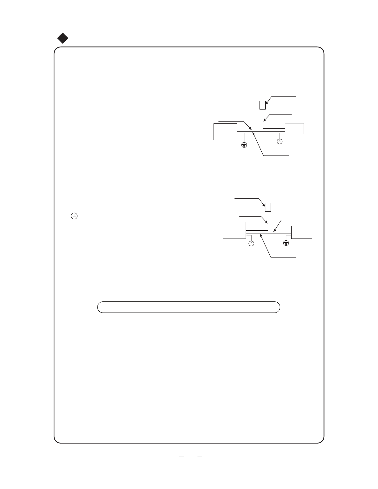
Σημείωση: η μονάδα θα πρέπει να εγκατασταθεί
σωστά ώστε να αποφευχθούν αναταράξεις και να
διασφαλίζεται η ανθρώπινη προστασία.
Καλώδιο σύνδεσης
Καλώδιο σύνδεσης
27
(380-415V 3N~/220V 3~)
(220V~)
Σημειώσεις για την εγκατάσταση
Καλώδιο
ενδοεπικοινωνίας
Καλώδιο
ενδοεπικοινωνίας
Εσωτερική
μονάδα
Εσωτερική
μονάδα
Γείωση
Γείωση
Παροχή
Παροχή
Παροχικό
καλώδιο
Ασφάλεια
Ασφάλεια
Παροχή ρεύματος
εσωτερικά και εξωτερικά
Παροχή ρεύματος
εσωτερικά και εξωτερικά
Για μονοφασική μονάδα
Για τριφασική μονάδα
Διάγραμα εγκατάστασης,
παρακαλούμε ανατρέξτε στο παρακάτω
Σημειώσεις για τη συνδεσμολογία:
1. Πρέπει να χρησιμοποιείται ειδικό κύκλωμα για παροχή
ρεύματος.
2. Το κύκλωμα πρέπει να εγκατασταθεί από
εξειδικευμένο προσωπικό.
3. Παρακαλούμε κάντε τη καλωδίωση σύμφωνα με το
ακόλουθο διάγραμμα.Οι βίδες πρέπει να στερεωθούν
σφικτά, οι λείες βίδες πρέπει να αλλαχθούν, η ταινία
βιδώματος δεν μπορεί να χρησιμοποιηθεί για
ηλεκτρολογική σύνδεση.
4. Παρακαλούμε κάντε την καλωδίωση σύμφωνα με το
ακόλουθο διάγραμμα.
5.
Χρησιμοποιήστε τα καλώδια που συνοδεύουν τη
μονάδα και μην κάνετε οποιαδήποτε μετατροπή στο
μήκος και στις άκρες του καλωδίου. Εάν χρεαστεί η
οποιαδήποτε μετατροπή, παρακαλούμε επικοινωνήστε
με το κέντρο εξυπηρέτησης πελατών.
6. Στο παροχικό καλώδιο που παρέχεται χωρίς βύσμα
δεν μπορεί να τοποθετηθεί βύσμα.
7. Τα παροχικά καλώδια σύνδεσης της εσωτερικής και
εξωτερικής μονάδας δεν θα πρέπει να είναι τεντωμένα ή
τσακισμένα.
8. Είναι το σύμβολο της γείωσης και υποδηλώνει πως
το κίτρινο-πραάσινο καλώδιο πρέπει να συνδεθεί σε
σημείο με το αντίστοιχο σύμβολο.
9. Αφού τελειώσετε την εγκατάσταση, βεβαιωθείτε πως
το παροχικό καλώδιο είναι στερωμένο, πως οι συνδέσεις
είναι σωστές και πως υπάρχει ικανοποιητική απόσταση
ανάμεσα στα καλώδια και τις συνδέσεις.
10. Παρακαλούμε χρησιμοποιήστε μισό κιλό τάσης, να
ελέγξετε πως κάθε καλωδίωση έχει εγκατασταθεί σωστά.
Αφότου ελέγξετε το σύνδεσμο αερισμού, παρακαλούμε
ελέγξτε ποιά καλωδίωση ενώνεται με τον σύνδεσμο.
Εξωτερική
μονάδα
Εξωτερική
μονάδα
① ② ③ ④
Απαιτήσεις γείωσης
1. Η κλιματιστική μονάδα είναι ενεργειακής κλάσσης Α.
2. Το κίτρινο-πράσινο καλώδιο είναι το καλώδιο για τη γείωση της μονάδας και
δεν μπορεί να χρησιμοποιηθεί για άλλους σκοπούς. μην το κόβετε και μην το
στερεώνετε απο τη λαμαρινόβιδα, μπορεί να προκληθεί ηλεκτροπληξία.
3. Η γείωση δεν πρέπει να είναι συνδεδεμένη στα παρακάτω:
Σωλήνα νερού Σωλήνα αεριου Σωλήνα αποχέτευσης συμπυκνωμάτων
Σε οποιοδήποτε μέρος θεωρείται ακατάλληλο
από εξειδικευμένο τεχνικό.
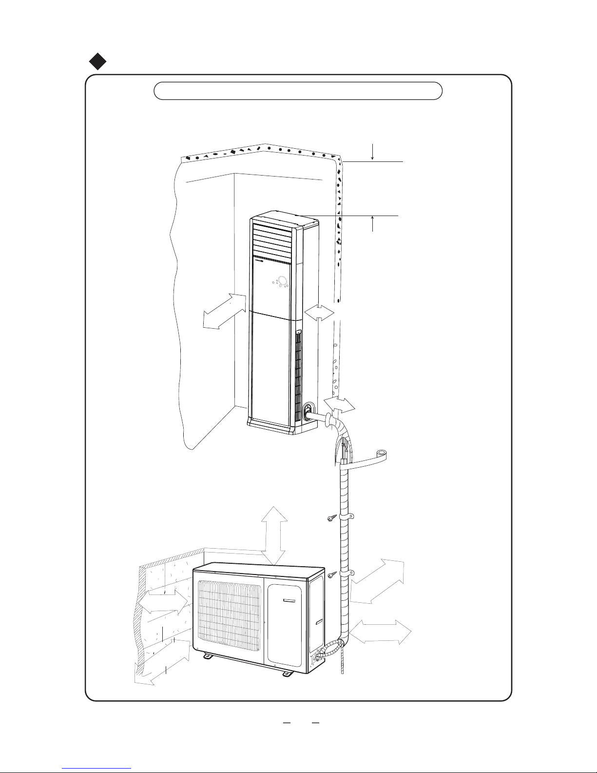
200cm
28
24K
30cm
10cm
5cm
Πάνω από 60cm
Σχηματικό Διάγραμμα Εγκατάστασης
Σχηματικό Διάγραμμα Εγκατάστασης
Απόσταση από τον τοίχο
Είσοδος αέρα
Έξοδος αέρα
Απόσταση από
τον τοίχο
Απόσταση από τυχόν εμπόδια
Απόσταση από την
πίσω πλευρά
Έξοδος αέρα
Απόσταση από τον τοίχο
(30cm τουλάχιστον από τη
μεριά των σωληνώσεων)
Απόσταση από την οροφή
Πάνω από 10cm
Πάνω από 60cm
Πάνω από 10cm
Πάνω από 200cm
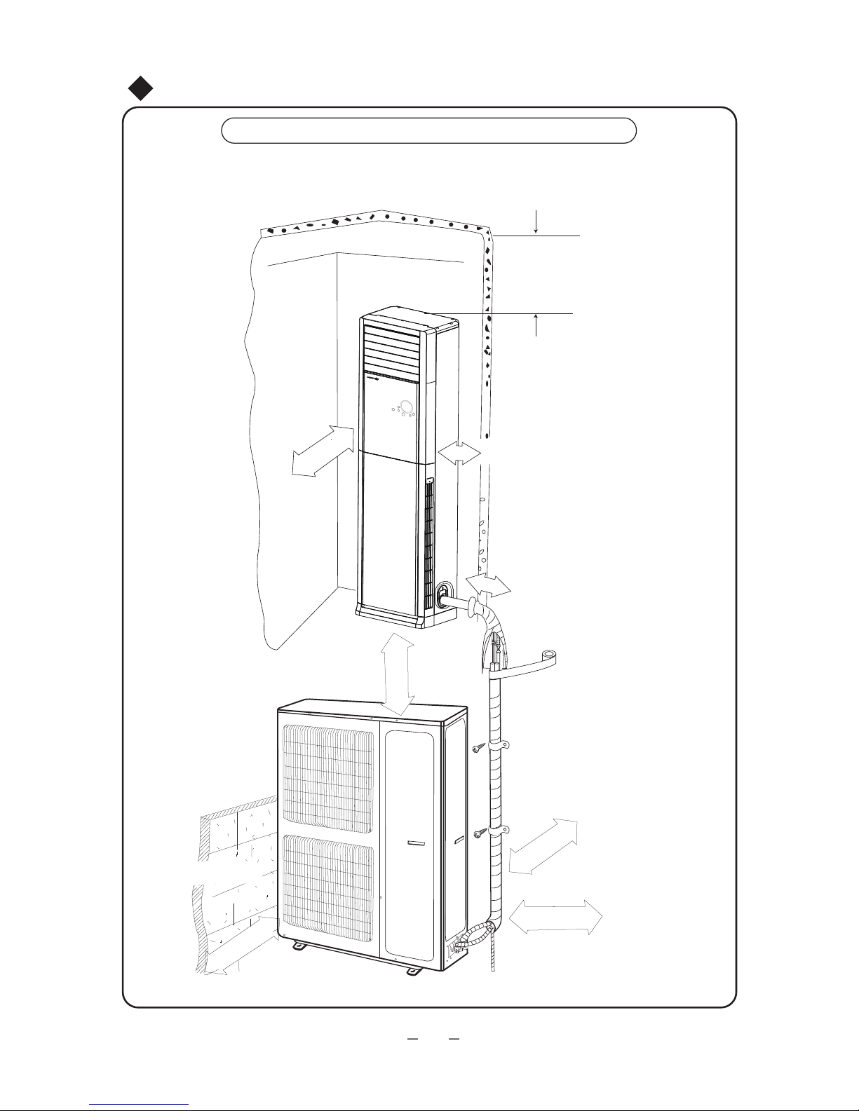
200cm
29
48K
30cm
10cm
5cm
Σχηματικό Διάγραμμα Εγκατάστασης
Σχηματικό Διάγραμμα Εγκατάστασης
Απόσταση από τον τοίχο
Είσοδος αέρα
Έξοδος αέρα
Απόσταση από
τον τοίχο
Απόσταση από τυχόν εμπόδια
Απόσταση από την
πίσω πλευρά
Έξοδος αέρα
Απόσταση από τον τοίχο
(30cm τουλάχιστον από τη
μεριά των σωληνώσεων)
Απόσταση από την οροφή
Πάνω από 60cm
Πάνω από 10cm
Πάνω από 60cm
Πάνω από 10cm
Πάνω από 200cm

1.Ανοίξτε το γυάλινο πάνελ.
2.Αφαιρέστε τη βίδα από το κάλυμμα
του κουτιού ηλεκτρικών συνδέσεων
και αφήστε το να εκτεθεί όπως φαίνεται
στο δεξί σχήμα.
Σωλήνα αποστράγγισης
Σωλήνα Ψυκτικού υγρού- Σύνδεση εκχείλωσης
Σωλήνα Ψυκτικού υγρού- Σύνδεση εκχείλωσης
Κάλυμμα ηλεκτρολογικού κουτιού
Σχέδιο εσωτερικής μονάδας
30
Εγκατάσταση του σωλήνα σύνδεσης
Πριν την καλωδίωση και τη σωλήνωση, παρακαλούμε
αφαιρέστε το πλέγμα εισόδου του αέρα.
Εγκατάσταση εσωτερικής μονάδας
Εγκατάσταση σωλήνα αποστράγγισης
Ηλεκτρική σύνδεση
Εικ.11
Εικ.12
Σωλήνα αποχέτευσης
συμπυκνωμάτων
Εικ.10
Πλέγμα
εισόδου αέρα
Σωλήνα
αποχέτευσης
συμπυκνωμάτων
Φλάντζα
Σύνδεση
σωλήνα
Υποδοχή σωλήνα
αποστάγγισης
Οπή σωλήνα
αποχέτευσης συμπυκνωμάτων
Μονωτική ταινία
Βίδα
Φλάντζα
1. Αφαιρέστε τις βίδες από τη δεξιά και
την αριστερή πλευρά του πλέγματος
εισόδου (όπως φαίνεται στην εικόνα 9).
Ανοίξτε το πλέγμα τραβώντας το από
τις λαβές με τη φορά του βέλους στη
θέση 3..
2. Για τη σύνδεση των σωληνώσεων
και της καλωδίωσης αριστερά, δεξία
και πίσω, χρησιμοποιήστε τα
εξαρτήματα που συνοδεύουν τη
μονάδα.
(όπως φαίνεται στην εικόνα 11)
1. Βεβαιωθείτε ότι ο σωλήνας αποστράγγισης οδηγεί στην εξωτερική πλευρά (πλευρά εκκένωσης).
2. Συνδέστε το σωλήνα αποστράγγισης με την υποδοχή του σωλήνα αποστράγγισης και στερεώστε
με ταινία από τον πρόσθετο εξοπλισμό.
3. Εάν ο σωλήνας αποστράγγισης πρέπει να είναι σε εσωτερικό χώρο, παρακαλούμε τυλίξτε τον με
μονωτικό υλικό (πάχους τουλάχιστον 9mm), και στη συνέχεια τυλίξτε με ταινία, για να αποτρέψετε
είσοδο αέρα στο σωλήνα και την πρόκληση παγώματος.
4. Μετά τη σύνδεση ελέγξτε εάν το νερό μπορεί να απομακρυνθεί κανονικά και εάν υπάρχει κάποια
διαρροή. (όπως φαίνεται στην εικόνα 12)
3. Περάστε το καλώδιο σύνδεσης από την
οπή που υπάρχει στην πίσω πλέυρα της
εσωτερικής μονάδας
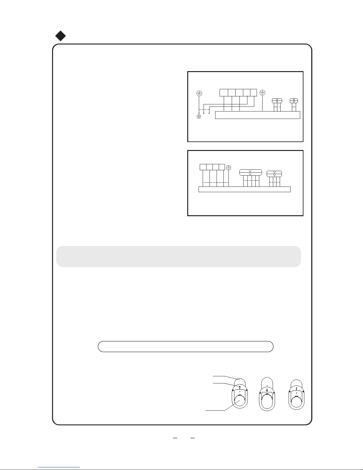
Τερματικό κουτί εξωτερικής μονάδας
Εικ.13
Ηλεκτρολογική συνδεσμολογία σύμφωνα με
το διάγραμμα:
7.
Τοποθετείστε το πλαίσιο
●
Βίδες
Οπή
Καπάκι
Εγκατάσταση Διακοσμητικού Καπακιού
1. Χαλαρώστε τις βίδες και προσαρμόστε τη θέση του καπακιού
πάνω και κάτω ώστε να κουμπώσει τη σωλήνα σύνδεσης/
σωλήνα αποστράγγισης όσο το δυνατόν καλύτερα.
2. Σφίξτε τις βίδες.
Εικ.14
Παρακαλούμε εγκαταστήστε το αφότου εγκαταστήσετε την σωλήνα
σύνδεσης και τη σωλήνα αποστράγγισης σύμφωνα με
την Εικ. 14.
31
48K
24K
N
L
μπλε
μπλε
μπλε
καφέ
καφέ
brown
μαύρο
μαύρο
βιολετί
κίτρινοπράσινο
κίτρινοπράσινο
κίτρινοπράσινο
L1 L2 L3 N
Σύνδεση εξωτερικής μονάδας
N(1)
2
3 L N
●
●
●
●
●
Σημείωση:
Σε περίπτωση που το μήκος του καλωδίου δεν επαρκεί, επικοινωνήστε με εξουσιοδοτημένο κατάστημα για την
προμήθεια ίδιου τύπου καλωδίου μεγαλύτερου μήκους. Δεν επιτρέπεται η μάτιση καλωδίων.
Λάθος συνδεσμολογία μπορεί να προκαλέσει βλάβη στα επιμέρους εξαρτήματα της μονάδας
Σφίξτε καλά τις βίδες
Αφού σφίξετε τις βίδες, τραβήξτε ελαφρώς το καλώδιο για να βεβαιωθείτε ότι έχει στερωθεί σωστά.
Λάθος γείωση μπορεί να προκαλέσει ηλεκτροπληξία.
Βεβαιωθείτε πως το κάλυμμα είναι στερεωμένο σωστά. Εάν δεν έχει γίνει σωστή τοποθέτηση, μπορεί να
εισχωρήσει σκόνη ή υγρασία ή εξαιτίας εξωτερικών παραγόντων να προκληθεί ηλεκτροπληξία ή
πυρκαγιά.
Εγκατάσταση εσωτερικής μονάδας
4. Σύμφωνα με το ηλεκτρολογικό
διάγραμμα και με τα σύμβολα πάνω
στην αντίστοιχη πλακέτα.
(όπως φαίνεται στην εικόνα 13)
5. Τοποθετήστε το άκρο του καλωδίου
στην αντίστοιχη επαφή. Τοποθετήστε το
κάλυμμα του κουτιού ηλεκτρικων συνδέσεων
και σφίξτε το καλώδιο.
6. Για τη μονάδα με καλώδιο σήματος, συνδέστε
το καλώδιο σήματος με τον σύνδεσμο. Κουμπώστε
το τμήμα του καλωδίου σήματος.
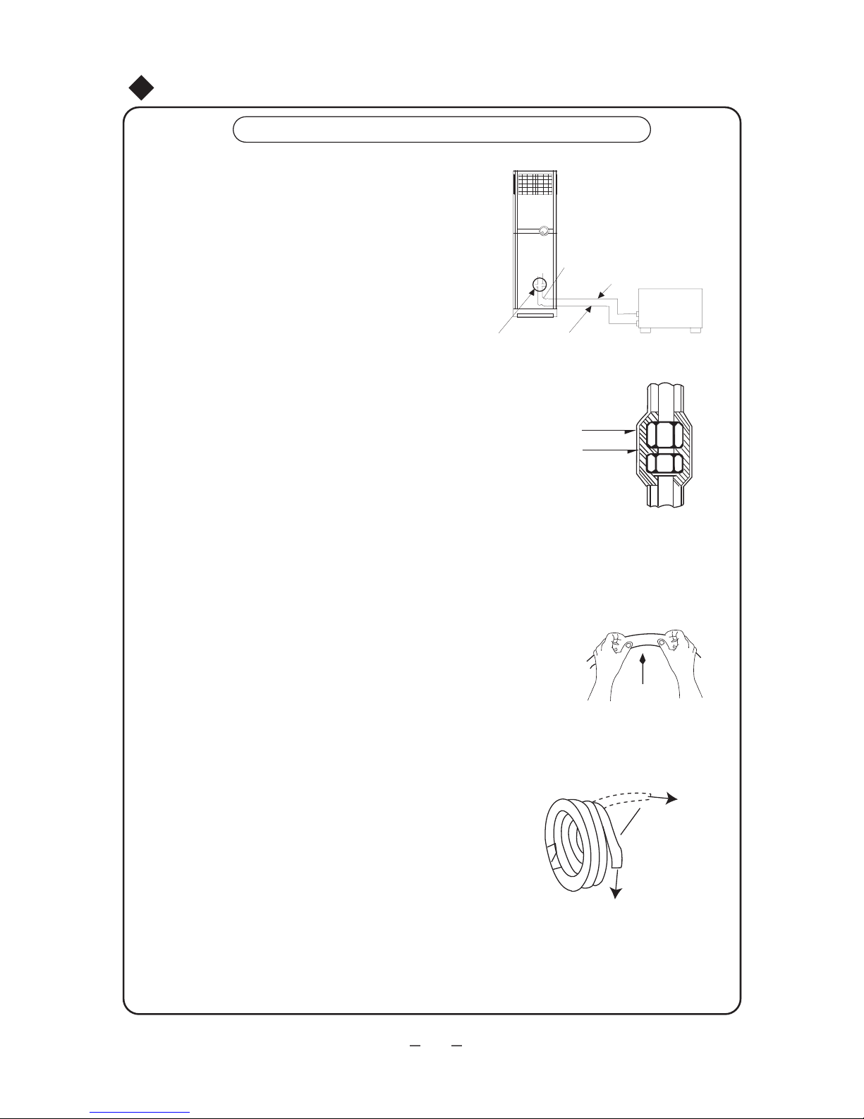
32
Eγκατάσταση εσωτερικής μονάδας
Σημειώσεις για τις σωληνώσεις
Ο αγωγός του ψυκτικού μέσου και ο αγωγός
αποστράγγισης θα πρέπει να είναι μονωμένοι
για να μην παγώνουν και να μην στάζουν.
2.
Εικ. 16
Εικ. 17
Εικ. 15
Ευκαμπτος αγωγός
Εσωτερική μονάδα
Εξωτερική
μονάδα
Σύνδεση
Ταινία πολυαιθυλενίου
Μόνωση
Λυγίστε τον αγωγό με τα χέρια
Ελάχιστη γωνία:100mm
Χαλαρώστε το ρολό
της σωλήνας και
ισιώστε την άκρη της
Τα άκρα της σύνδεσης και της εσωτερικής και
της εξωτερικής μονάδας διαθέτουν εκχείλωση.
Όπως φαίνεται παρακάτω, ο αγωγός του
ψυκτικού μέσου χρησιμοποιείται για τη
σύνδεση της εσωτερικής και της εξωτερικής
μονάδας.(Όπως φαίνεται στην Εικ. 15)
Σημείωση: Μην λυγίζετε τον εύκαμπτο αγωγό
προς τα εμπρός και προς τα πίσω περισσότερο
από 3 φορές. Μονώστε όλες τα εκτεθειμένα μέρ
στη σύνδεση εκχείλωσης και στη σωλήνα ψυκτικού
υγρού. (Όπως φαίνεται στην Εικ. 16)
1.
Σύνδεση του αγωγού
Η βαλβίδα ελέγχου της εξωτερικής μονάδας θα πρέπει
να είναι κλειστή (π.χ. ανενεργή). Κατά τη σύνδεση,
αφαιρείτε κάθε φορά το κάλυμμα της βαλβίδας ελέγχου
και συνδέετέ τη αμέσως με τον αγωγό με τα ενδέχεται
να εισχωρήσουν στον αγωγό σκόνη, υγρασία και άλλα
μικρά αντικείμενα και να προκληθεί πρόβλημα.
• Πληροφορίες για τον εύκαμπτο αγωγό.
1. Το τμήμα με τον εύκαμπτο αγωγό θα πρέπει να
χρησιμοποιείται στην πλευρά του εσωτερικού χώρου.
2. Ο αγωγός δεν θα πρέπει να κάμπτεται σε γωνία
άνω των 90 μοιρών.
3. Προτιμάτε να λυγίζετε τον αγωγό στη μέση, και με
ακτίνα κάμψης όσο το δυνατόν μεγαλύτερη.
4. Μην λυγίζετε τον εύκαμπτο αγωγό περισσότερες
από τρεις φορές.
• Όταν λυγίζετε τον αγωγό
1. Κόψτε ένα τμήμα της μόνωσης του αγωγού στο σημείο
της κάμψης (και τυλίξτε τον με μονωτική ταινία
από πολυαιθυλένιο, αφού τον λυγίσετε)
2. Κάνετε την ακτίνα κάμψης όσο μεγαλύτερη γίνεται ώστε
να μην ασκείται πίεση στον αγωγό και να μην υπάρχει ο
κίνδυνος να σπάσει.
3. Σφίξτε τον εύκαμπτο αγωγό με λαστιχένιο κουρμπαδόρο.
• Όταν χρησιμοποιείτε χάλκινο αγωγό που προμηθευτήκατε μόνοι σας
Η βαλβίδα ελέγχου της εξωτερικής μονάδας θα πρέπει να
είναι κλειστή (π.χ. ανενεργή). Αφού ο αγωγός ψυκτικού
μέσου συνδεθεί με την εσωτερική και την εξωτερική μονάδα,
εξαερώστε τον από το στόμιο πρόσβασης συντήρησης στη
βαλβίδα ελέγχου χαμηλής πίεσης της εξωτερικής μονάδας.
Μετά την εξαέρωση, τοποθετήστε στη θέση του το παξιμάδι
του στομίου πρόσβασης συντήρησης και στερεώστε το.
Μετά την ολοκλήρωση των βημάτων 1 και 2, η βαλβίδα ελέγχου της εξωτερικής μονάδας
θα πρέπει να είναι εντελώς ανοιχτή ώστε να μην παρεμποδίζεται σε κανένα σημείο ο
αγωγός ψυκτικού μέσου μεταξύ της εσωτερικής και της εξωτερικής μονάδας.
Σημείωση: Προτού στερεώσετε το παξιμάδι του αγωγού με εκχειλωμένα άκρα,
επαλείψτε το άκρο του αγωγού και την ένωση με ψυκτικό λάδι.

●
B
C
D
A
Κλειδί
Κλειδί ροπής
Σωλήνωση εσ. μονάδας
παξιμάδι
Σωλήνωση
Ф 9.52
Ф 16
60~65
35~40
Ф 6
15~20
Ф 12
50~55
Ф 19
70~75
Μέθοδος εκκένωσης
Μήκος αγωγού σύνδεσης Πλήρωση ψυκτικού μέσου
Χρήση ψυκτικού
υγρού εξωτερικής
μονάδας
Κάτω από 5m
Ίδια τιμή με αυτή στη πινακίδα
Χρήση αντλίας κενού
Χρήση αντλίας κενού
5-15m
20-30m
μοντέλο με τιμή στη πινακίδα +30g/m
μοντέλο με τιμή στη πινακίδα+100g/m
33
Εγκατάσταση εξωτερικής μονάδας
Εγκατασταση σωλήνα σύνδεσης
Διάμετρος (mm) Ροπή (N.m)
Εικ.18
Γραμμή αερίου
Εξωτερική μονάδα
Εσωτερική μονάδα
Αντεπίστροφη
βαλβίδα
Σύνδεσμος
αγωγού
Παξιμάδι βαλβίδας
Όριο ασφάλισης
Κάλυμμα
Στέλεχος βαλβίδας
Βαλβίδα
1. Ευθυγραμμίστε το κέντρο του σπειρώματος της σωλήνας με την
αντίστοιχη βάνα
2. Βιδώστε το παξιμάδι με το χέρι και στη συνέχεια σφίξτε το με
κλειδί (δείτε τον πίνακα παρακάτω).
Κατά τη χρήση του ψυκτικού μέσου της εξωτερικής
μονάδας:
1. Σφίξτε αρκετά τα παξιμάδια Α, Β, Γ, Δ.
2. Αφαιρέστε το κάλυμμα από τη βαλβίδα ελέγχου Α.
(όπως φαίνεται στην Εικ. 18)
3. Στρίψτε και ανοίξτε το επιστόμιο της βαλβίδας
υγρού Β με το εξαγωνικό κλειδί, και ταυτόχρονα
πιέστε με το κατσαβίδι το επιστόμιο της βαλβίδας
αερίου Α για να εξέλθει το αέριο. Μετά από 15
δευτερόλεπτα εξαέρωσης και μόλις εμφανιστεί το
ψυκτικό μέσο, κλείστε τη μονόδρομη βαλβίδα και
σφίξτε το κάλυμμα.
4. Ανοίξτε πλήρως τα επιστόμια και της βαλβίδας
υγρού και της βαλβίδας αερίου,σφίξτε το κάλυμμα
και στη συνέχεια ελέγξτε με σαπουνόνερο ή
ανιχνευτή διαρροών αν παρατηρείται κάποια
διαρροή στις ενώσεις των αγωγών μεταξύ της
εσωτερικής και της εξωτερικής μονάδας.
Σημείωση: Συνδέστε πρώτα το σωλήνα σύνδεσης με την εσωτερική μονάδα και μετά με την
εξωτερική μονάδα. Δώστε προσοχή κατά το λύγισμα του αγωγού και προσέχετε να μην
σφίγγετε υπερβολικά το παξιμάδι, γιατί μπορεί να καταστραφεί και να προκληθεί διαρροή.
Δημιουργία κενού (με εξαγωνικό κλειδί Α5mm)

When using vacuum pump
Εικ.20
Σημείο ελέγχου διαρροής εσωτερικής μονάδας
Σημείο ελέγχου διαρροής εξωτερικής μονάδας
34
Εγκατάσταση εξωτερικής μονάδας
-76cmHg
Βαλβίδα πολλαπλής εισαγωγής
Μανόμετρο
Μανόμετρο
Λαβή
χαμηλής πίεσης
Σωλήνας φόρτισης
Βαλβίδα
χαμηλής πίεσης
Εικ.19
Αντλία κενού
Λαβή
υψηλής πίεσης
Σωλήνας
φόρτισης
1. Συνδέστε τον σωλήνα φόρτισης της βαλβίδας του μανομέτρου στο
άκρο φόρτισης της βαλβίδας χαμηλής πίεσης (και οι βαλβίδες χαμηλής
πίεσης και οι βαλβίδες υψηλής πίεσης πρέπει να κλείνουν με
ασφάλεια).
2. Συνδέστε το σωλήνα φόρτισης με την αντλία κενού.
3. Ανοίξτε εντελώς τη λαβή της βαλβίδας του μανομέτρου Lo.
4. Ανοίξτε την αντλία κενού για εκκένωση. Στην αρχή, χαλαρώστε
ελαφρώς το παξιμάδι συναρμογής της βαλβίδας χαμηλής πίεσης για
να ελέγξετε εάν εισέρχεται αέρας στο εσωτερικό. Αφού ολοκληρώσετε
την εκκένωση, κλείστε τη λαβή Lo της
βαλβίδας της πολλαπλής για να σταματήσετε την αντλία κενού.
(Συνεχίστε την εκκένωση για περισσότερο από 15 λεπτά και
επιβεβαιώστε ότι η ένδειξη του μανόμετρου είναι -1,0 x 10⁵pa
(-76cmHg)
5.Αφαιρέστε τον σύνδεσμο πλήρωσης από τη βαλβίδα αερίου.
6. Ανοίξτε πλήρως τη βαλβίδα αερίου και τη ρευστού.
7. Σφίξτε το καπάκι της βαλβίδας χαμηλής πίεσης. (Όπως φαίνεται
στην Εικ. 19)
Ø
Αποστράγγιση συμπυκνωμάτων εξωτερικής μονάδας
(μόνο για μονάδες τύπου αντλίας θερμότητας)
Γωνία αποστράγγισης
εξωτερικής μονάδας
Βάση
Όταν θερμαίνεται η μονάδα, το νερό των συμπυκνωμάτων
και το νερό της απόψυξης μπορεί να αποστραγγιστεί με
αξιοπιστία μέσω του σωλήνα αποστράγγισης.
Εγκατάσταση:
Εγκαταστήστε τον εξωτερικό βραχίονα
αποστράγγισης σε μία οπή 25 στην
βάση και συναρμόστε τον σωλήνα
αποστράγγισης στον βραχίονα, έτσι ώστε
τα νερά της αποχέτευσης που
συγκεντρώνονται στην εξωτερική μονάδα
να μπορούν να αποστραγγιστούν σε ένα
κατάλληλο μέρος.
Χρησιμοποιήστε νερό ή έναν μετρητή εντοπισμού διαρροών για να ελέγξετε εάν υπάρχει
διαρροή στις ενώσεις (όπως φαίνεται στην εικ.20). Ελεγκτής διαρροής αν είναι δυνατόν,
μπορεί να χρησιμοποιηθεί.
Έλεγχος για διαρροές

35
1. Αφαιρέστε το μπροστινό πλαίσιο
2. Ανατρέξτε στο αντίστοιχο ηλεκτρολογικό
διάγραμμα της εσωτερικής μονάδας για
τη συνδεσμολογία. (όπως φαίνεται
στην εικ. 21)
Εικ.21
Πλακέτα
Πλακέτα
Πλαινό
καπάκι
Πλαινό
καπάκι
Οπή καλωδίου
Οπή καλωδίου
Παροχικό
καλώδιο
σύνδεσης
Καλώδιο σήματος
Καλώδιο σήματος
Μπροστινό
πλαίσιο
Καλώδιο σήματος
της εσωτερικής
μονάδας
Καλώδιο σήματος
της εσωτερικής
μονάδας
Καλώδια σήματος
24K:
48K :
24K
μπλε
καφέ
μαύρο
κίτρινοπράσινο
N1 2 3
Σύνδεση Εξωτερική μονάδας
Σύνδεση εσωτερικής μονάδας
L2N L1
L3 L2 L1
N
L3 L2N L1L3
μπλε
βιολετί μαύρο καφέ
μπλε
βιολετί μαύρο καφέ
κίτρινοπράσινο
κίτρινοπράσινο
ΡΕΥΜΑ
48K
Εγκατάσταση εξωτερικής μονάδας
Μέθοδος καλωδίωσης
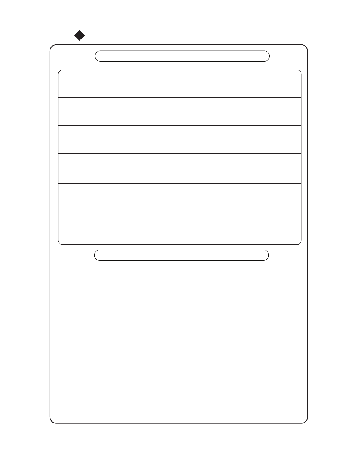
36
1.
2.
Δοκιμή λειτουργίας και έλεγχος μετά την εγκατάσταση
Έλεγχος μετά την εγκατάσταση
Στοιχεία προς έλεγχο
Πιθανό σφάλμα
Έχει εγκατασταθεί σταθερά;
Η συσκευή μπορεί να πέσει, να κινηθεί ή να
εκπέμπει θόρυβο
Έχετε εκτελέσει τον έλεγχο διαρροής για
το ψυκτικό υγρό;
Μπορεί να προκαλέσει μειωμένη απόδοση
ψύξης (θέρμανσης).
Επαρκεί η θερμική μόνωση;
Μπορεί να προκληθεί υγροποίηση και στάξιμο
Γίνεται σωστά η αποστράγγιση υδάτων;
Μπορεί να προκληθεί υγροποίηση και στάξιμο
Η τάση συμμορφώνεται με την τάση που
αναγράφεται στην πινακίδα τεχνικών στοιχείων;
Μπορεί να προκληθεί ηλεκτρική δυσλειτουργία ή βλάβη στη μονάδα.
Έχει εγκατασταθεί σωστά και με ασφάλεια
η ηλεκτρική καλωδίωση και η σωλήνωση;
Μπορεί να προκληθεί ηλεκτρική δυσλειτουργία ή βλάβη στη μονάδα.
Έχει συνδεθεί η συσκευή με μία ασφαλή
σύνδεση γείωσης;
Μπορεί να προκληθεί διαρροή ηλεκτρικού
ρεύματος
Το καλώδιο τροφοδοσίας είναι αυτό που
έχει καθοριστεί;
Μπορεί να προκληθεί ηλεκτρική δυσλειτουργία ή βλάβη στη μονάδα.
Έχει καλυφθεί η έξοδος και η είσοδος
αέρα;
Μπορεί να προκαλέσει μειωμένη απόδοση
ψύξης (θέρμανσης).
Έχει καταγραφεί το μήκος των σωλήνων
σύνδεσης και η ικανότητα του ψυκτικού
μέσου;
Η απόδοση ψύξης δεν είναι ακριβής.
Δοκιμαστική λειτουργία
Πριν τη δοκιμαστική λειτουργία
Μέθοδος δοκιμαστικής λειτουργίας
(1) Ανάψτε το ρεύμα, πατήστε το πλήκτρο "ON/OFF" στο ασύρματο τηλεχειριστήριο για να
ξεκινήσει η λειτουργία.
(2) Πιέστε το πλήκτρο MODE, για
να επιλέξετε τη λειτουργία COOL, HEAT, FAN και να ελέγξετε
εάν η λειτουργία είναι κανονική ή όχι.
(1) Μην ανάβετε το ρεύμα πριν τελειώσει εντελώς η εγκατάσταση.
(2) Η ηλεκτρική καλωδίωση πρέπει να συνδεθεί σωστά και με ασφάλεια.
(3) Οι βαλβίδες αποκοπής των σωλήνων σύνδεσης θα πρέπει να είναι ανοιχτές.
(4) Πρέπει να απομακρυνθούν από τη μονάδα, όλοι οι ρύποι όπως μικρά κομμάτια και
γρατζουνιές.

Ενεργοποιήστε την εγγύηση σας...
σε
5
απλά
Συνδεθείτε στο site της
στον ακόλουθο σύνδεσµο
http://www.inventoraircondition.gr/
egiisi-inventor/
Επιλέξτε τον τύπο του προϊόντος
(κλιµατιστικό ή συσκευή) για το
οποίο θα ενεργοποιηθεί η εγγύηση
Συµπληρώστε τα απαιτούµενα
στοιχεία (κατόχου, εµπόρου και
συσκευής) και πατήστε αποστολή
Επιλέξτε την εγγύηση
που αντιστοιχεί στο προϊόν
που έχετε στην κατοχή σας
Θα λάβετε επιβεβαιωτικό
µήνυµα στο e-mail σας για
την ενεργοποίηση της εγγύησης
Για την υποβολή
ηλεκτρονικών εγγυήσεων
πληκτρολογήστε
την παρακάτω διεύθυνση
https://www.inventoraircondition.gr/egiisi-inventor
Σκανάρετε εδώ
για τα έντυπα
των εγγυήσεων
Inventor

Note cu privire la folosirea aparatului
.....................................4
Denumirea partilor componente
............................................6
Folosirea telecomenzii
.....................................................12
Cuprins
Utilizare si mentenanta
Curatenie si mentenanta
..................................................20
Depanare .......................................................................22
Diagrama instalarii ...........................................................28
Instalarea unitatii interioare
................................................30
Instalarea unitatii exterioare ...............................................34
Verificarile si testarea instalarii ...........................................36
Instalarea
Atentionari cu privire la operarea aparatului .............................1
Note cu privire la instalare .................................................25
Modificarea directiei fluxului de aer ......................................17
Folosirea functiilor speciale ................................................19
Acest simbol reprezinta
actiunile interzise.
Imaginile din acest manual pot fi diferite fata de aparatul pe care l-ati
achizitionat. Urmati exemplele in conformitate cu produsul dumneavoastra.
Acest simbol reprezinta actiunile
care trebuie urmate
Prezentarea butoanelor si functiilor acestui aparat ...................8
Nu aruncati acest aparat impreuna cu deseul municipal
nesortat. Acest aparat va fi colectat separat.
Este interzisa utilizarea aparatului de catre persoane (incluzand copii) cu
dizabilitati fizice, senzoriale si mentale. Utilizarea aparatului de catre persoanele mentionate mai sus sau de catre persoane fara experienta, va fi posibila
numai in cazul in care au fost instruite in acest sens. Asigurati-va ca supraveghiati copii.

★
★
★
Cititi cu atentie acest manual inainte de folosire.
AVERTIZARI
Opriti aparatul
Atentionari cu privire la operarea aparatului
1
Daca simititi miros de fum,
intrerupeti alimentarea cu
energie electrica si contactati
centrul de service.
Daca problema persista, aparatul
ar putea fi defect si exista riscul
de socuri electrice si incendiu.
Pentru a evita pericolul
aparitiei unui incendiu, asigurati
un circuit separat pentru acest
aparat.
Nu folositi un stecher pentru mai
multe aparate. Folositi o singura
priza pentru aparatul de aer
conditionat.
Daca nu utilizati apratul
pentru o perioada lunga de
timp, scoateti-l din priza.
Acumularile de praf, pot duce la
supraincalzire si incendiu.
Nu deteriorati cablul de
alimentare. Nu folositi un cablu
de alimentare necorespunzator
Pericol de supraincalzire si
incendiu
Asigurati-va ca instalatia
electrica si tensiunea sunt
stabile. Componentele electrice
se pot defecta in cazul unei
fluctuatii de tensiune. Sistemul
de racire, componentele
electrice si compresorul nu vor
functiona daca tensiunea este
prea joasa.
Cablul de alimentare trebuie
progejat de un dispozitiv de
inalta capacitate. Nu opriti
frecvent aparatul de aer
conditionat.
In timpul curatirii aparatului,
intrerupeti alimentarea cu
energie electrica.
Pericol de soc electric sau
defectare
Pericol de soc electric.
Nu folositi aparatul cand
aveti mainile ude.
Nu taiati si nu deteriorati
cablurile de alimentare sau
semnal. In cazul deteriorarii,
aceste cabluri pot fi inlocuite
doar de catre persoane
autorizate.
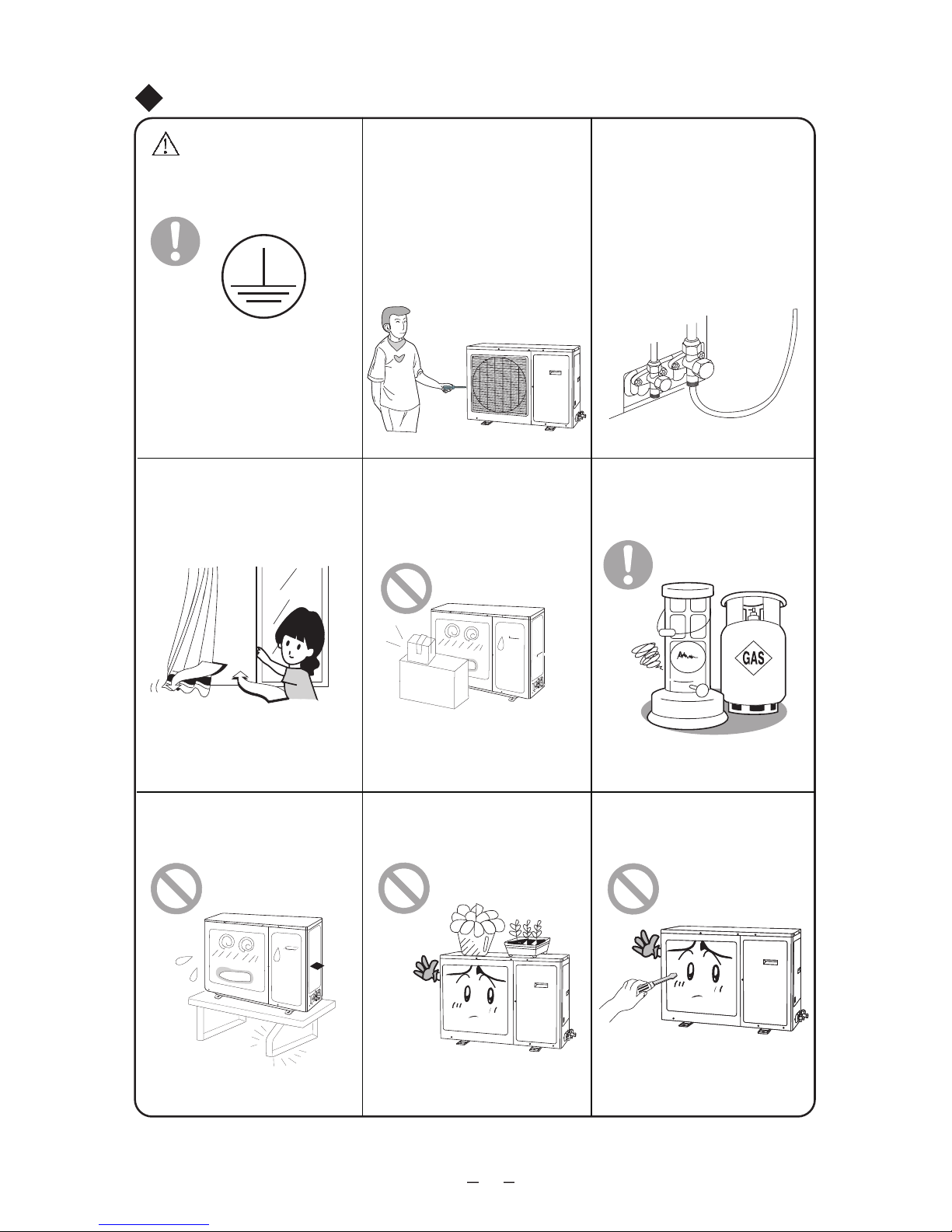
2
★
★
★
Atentionari cu privire la operarea aparatului
Pentru a evita defectiunile, nu
introduceti obiecte straine in aparat.
Nu introduceti mainile in gurile de
evacuare ale unitatilor exterioare
Operarea valvei unitatii exterioare
trebuie facuta de catre personal
autorizat, pentru a evita defectarea
compresorului sau a scurgerilor.
★
★
Nu obturati gurile de admisie/evacuare aer ale unitatilor interioare/exterioare
★
Nu tineti usile sau ferestrele
deschise pentru o perioada lunga in
timpul functionarii aparatului.
Spray-urile sau alte obiecte
presurizate trebuie tinute la cel putin 1
metru departare de unitatea
interioara.
Pericol de scadere a eficientei, oprire a
aparatului sau chiar incendii.
Acest fapt va duce la scaderea
eficientei aparatului.
Pericol de incendiu sau explozie.
★
★
Nu va urcati si nu asezati nimic pe
unitatea exterioara.
★
Verificati integrigtatea consolelor. Nu reparati dumneavoastra
aparatul.
Pericol de cadere.
In cazul in care consolele nu sunt
suficient de robuste, unitatea
exterioara va cadea. Pericol de ranire.
Reparatiile incorect pot cauza soc
electric sau incendiu. Contactati
departamentul de service pentru orice
lucrare.
Impamantarea
Impamantarea trebuie realizata
corect. Conectati cablul de
impamantare la cladire.
Daca impamantarea la cladire nu este
posibila, mentionati acest fapt
instalatorului. Nu conectectati cablul de
impamantare la conducte de gaz, apa
sau scurgere.

Atentionari cu privire la operarea aparatului
3
★
Nu introduceti mana sau obiecte straine in gurile de
evacuare/admisie aer.
★
Alegeti temperatura potrivita incaperii.
Asigurati-va ca diferenta
intre temperatura exterioara
si cea interioara nu este
foarte mare.
★
Nu stropiti aparatul cu apa. Pericol de soc electric sau
defectiune
★
Nu permiteti animalelor sa stea in fluxul de aer degajat
de aparatul de aer conditionat. Sanatatea animalelor de
companie sau a plantelor asezate in fluxul de aer, poate fi
afectata.
★
Nu petreceti foarte mult timp in contact direct cu fluxul
de aer si nu setati temperaturi foarte scazute.
★
Nu asezati aparatul de aer conditionat langa surse de
caldura.
Arderea incompleta poate duce la intoxicatie cu monoxid de
carbon (CO).
★
Nu folositi aparatul de aer conditionat in alte scopuri,
cum ar fi uscarea hainelor sau conservarea alimentelor.
★
Nu loviti usa de sticla.

Modul de functionare si functiile speciale pentru racire
Modul de functionare si functiile speciale pentru incalzire
Note cu privire la folosirea aparatului
4
Mod de functionare:
Aparatul de aer conditionat absoare aerul cald din incapere, acesta fiind eliminat pentru ca
temperatura din incapere sa poata fi scazuta. Conform acestui mod de functionare,
capacitatea de racire va scadea in cazul cresterii temperaturii externe.
Functia "Anti-Inghet"
Atnci cand aparatul functioneaza in modul de racire, la temperaturi scazute, pe suprafata
dispozitivului de schimbare a caldurii, poate aparea inghetul. Atunci cand temperatura
schimbatorului de caldura scade sub -2°C, un senzor interior va opri compresorul pentru
proteja aparatul.
Functia "Anti aer rece":
In timpul functiei de incalzire, daca dispozitivul de transfer al caldurii nu ajunge la o anumita
temperatura, ventilatorul interior nu va porni, pentru a evita degajarea de aer rece (timp de
90s).
Cele 3 cazuri in care ventilaotul nu va porni sunt mentionate mai jos :
1. La activarea functiei de incalzire;
2. Dupa auto dezghetare;
3. Incalzire la temperaturi foarte scazute.
* Aparatul absoare aerul cald din exterior si il distribuie in interior pentru ca temperatura
interioara sa creasca.
Nota: Conform acestui mod de functionare, capacitatea de incalzire va scadea in cazul
scaderii temperaturii externe.
Daca termperatura scade foarte mult, va rugam sa folositi alte echipamente de incalzire.
Dezghetarea
* Atunci cand termperatura exterioara este scazuta si nivelul umiditatii este crescut,
schimbatorul de caldura exterior va fi afectat de gheata, daca aparatul este folosit o
perioada lunga de timp, acest fenomen va afecta capacitatea de incalzire. In acel moment,
functia de auto dezghetare va fi activata si functia de incalzire va fi dezactivata pentru 5-10
minute.
* Intimpul dezghetarii automate, ventilatoarele unitatilor interioare si exteriorare se vor opri.
* In timpul dezghetarii automate, unitatea exterioara va degaja vapori datorita dezghetarii
rapide. Acesta este un fenomen normal, nu o defectiune.
* La finalizarea dezghetarii, functia de incalzire va porni automat.

★
Situatii in care unitatea nu va functiona in parametrii normali
Note cu privire la folosirea aparatului
5
In functie de situatiile mentionate mai jos, senzorii de protectie ai aparatului se vor activa
sau dezactiva :
Daca nivelul umiditatii creste peste 80% (usile si ferestrele deschise) si functia de racire sau
dezumidificare este activata pentru o perioada lunga, pot aparea scurgeri de apa.
Afisarea temperaturii ambientale
1. Pentru a perlungii durata de viata a compresorului, aparatul de aer conditionat va porni si
va opri compresorul in functie de conditiile din incapere. Compresorul nu se va opri
imediat ce temperatura setata a fost atinsa.
2. Datorita diferentelor temperatura din diferite parti ale incaperii, aparatul va ajusta nivelul
temperaturii pentru a asigura confortul. Temperatura afisata poate fi diferita fata de cea
detectata de utilizator.
Temperatura
exterioara peste
48°C
Temperatura
exterioara sub
21°C
Temperatura exterioara
peste 24°C
Temperatura exterioara
sub -7°C
Temperatura incaperii
peste 27°C
Functia
de racire
Functia de
dezumidifi-
care
Temperatu-
ra exterioara
sub 18°C
Functia de
incalzire

⑹
Unitatea interioara
Evacuarea
aerului
Unitate exterioara
(1) Gura de
evacuare a aerului
(2) Afisajul si
butoanele
(3) Panoul frontal
(4) Tubulatura de
conectare
(5) Tubulatura
scurgere
(6) Banda de
infasurare
Denumirea partilor componente ale aparatului
⑵
⑴
⑶
⑸
(4)
Evacuare aer
Admisie aer
Afisajul
24000 BTU
6
Admisia
aerului
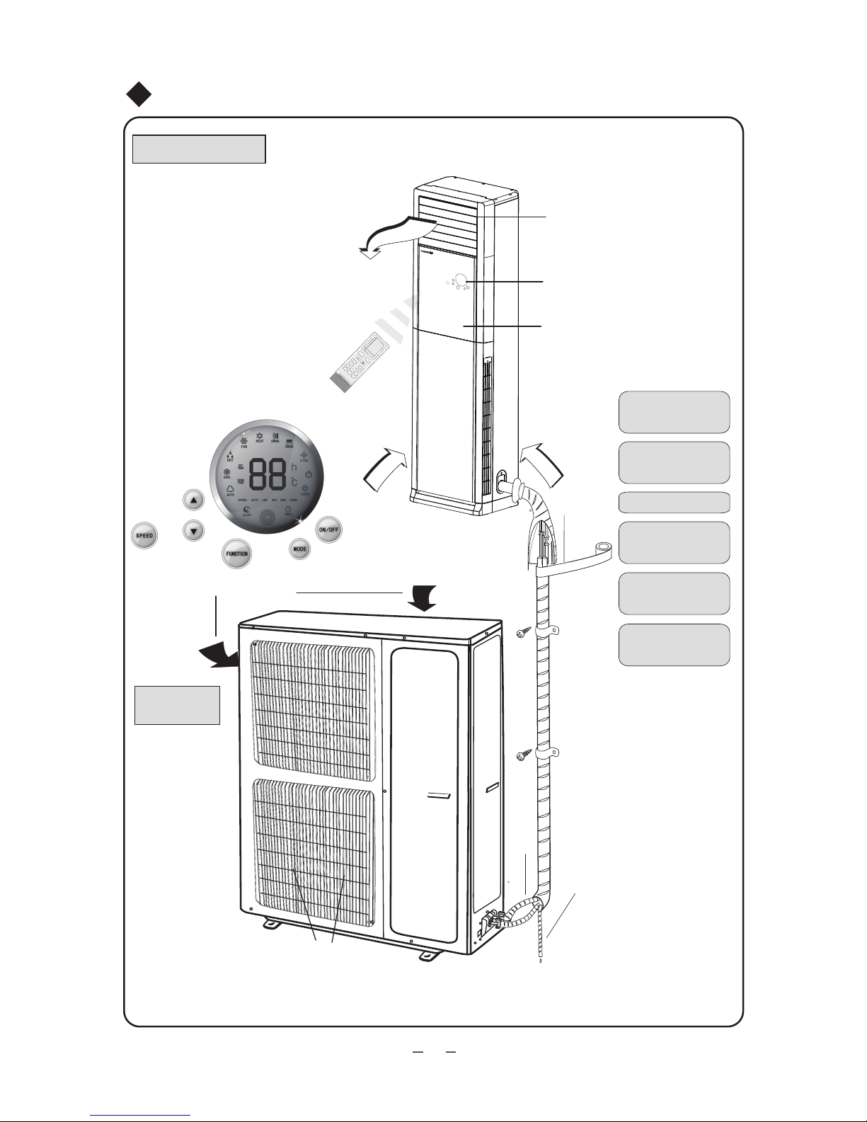
⑹
Unitatea interioara
Evacuare aer
Admisie
aer
(1) Gura evacuare
aer
(2) Afisajul si
butoanele
(3) Panoul frontal
(4) Tubulatura de
conectare
(5) Tubulatura de
scurgere
(6) Banda de
infasurare
Denumirea partilor componente ale aparatului
⑵
⑴
⑶
Afisajul
(4)
⑸
Unitate
exterioara
Admisie aer
Evacuare aer
7
48000 BTU
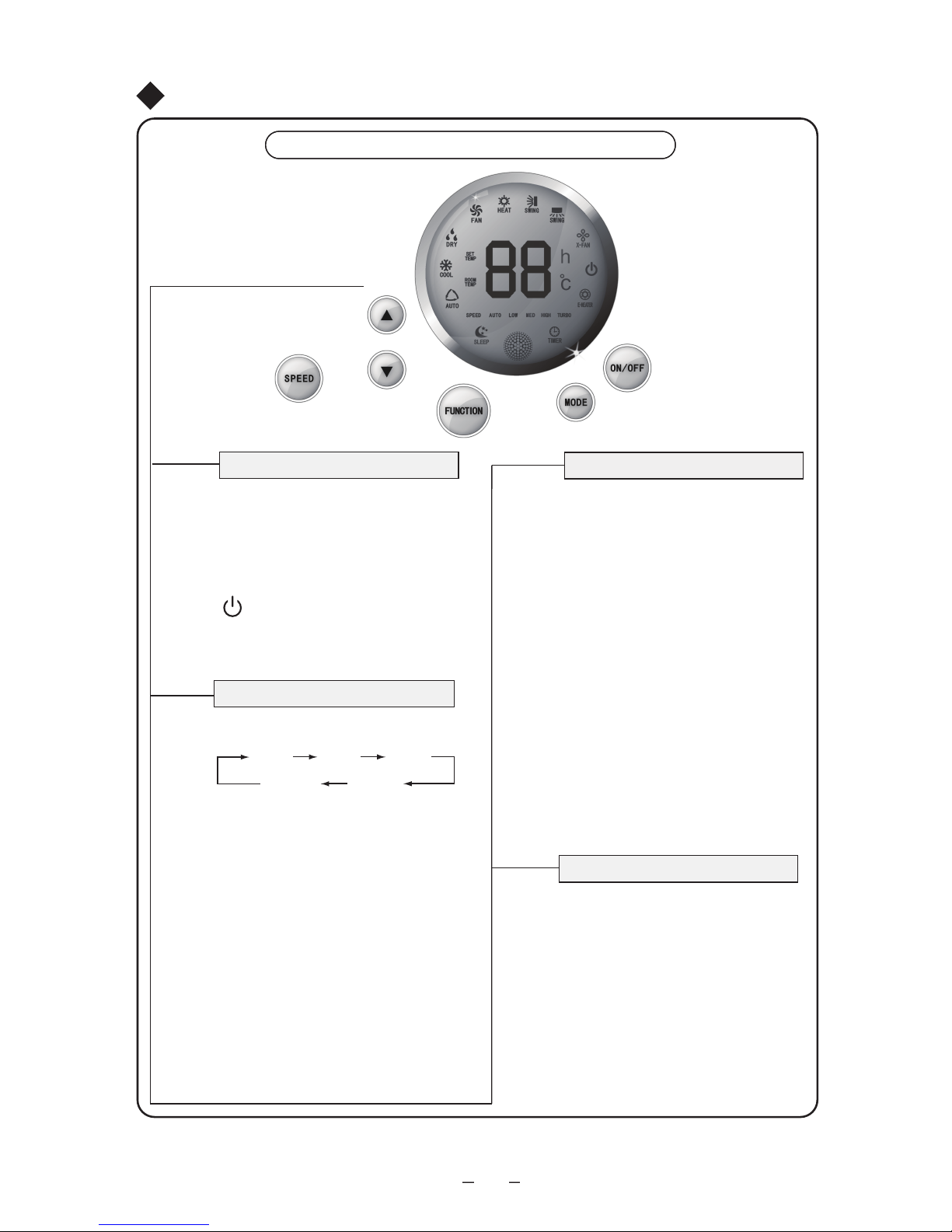
8
Butoanele si afisajul aparatului
ON/OFF
●
Butonul ON/OFF
●
Prezentarea butoanelor si functiilor acestui aparat
MODE
AUTO COOL
HEAT
DRY
FAN
●
●
●
●
Butonul Function
FUNCTION
Butoanele aparatului
Butonul MODE
SPEED
Butonul SPEED
Apasati butonul SPEED pentru a
selecta viteza ventilatorului, in
urmatoarea succesiune:
AUTO-LOW-MED-HIGH-AUTO
Apasati acest buton pentru a porni/opri
aparatul. La pornirea/oprirea aparatului,
functia SLEEP sau Temporizator, vor fi
anulate.
Nota: In timpul functionarii in modul
dezumidificare, aparati butonul ON/OFF
pentru a opri aparatul.
Apasand acest buton, veti putea alege
modul de functionare in ordinea urmatoare:
AUTO: In acest mod, functionarea va fi
automata, conditiile fiind determinate
automat de catre senzori, in functie de
temperatura interioara.
COOL: statusul racirii incaperii va fi afisat.
DRY (dezumidificare): Nivelul umiditatii va
scadea fara sa afecteze temperatura
incaperii.
FAN (ventilare): In acest mod compresorul
va fi oprit si doar ventilatorul va fi pornit.
HEAT (incalzire): statusul va fi afisat.
Nota: functia de incalzire nu este disponibila
la aparatele care au doar functie de racire.
Simbolul va afisa culoarea verde
atunci cand aparatul este pornit si culoarea
rosie atunci cand este oprit.
Cand aparatul este pornit, apasati
butonul FUNCTION pentru a va alege
functia dorita, in ordinea urmatoare:
oscilare verticala, oscilare orizontala,
X-FN, E-Heater, TIMER, SLEEP, SET
TEMP, ROOM TEMP.
Folositi butonale sus/jos ▲/▼pentru a
va alege functia dorita. Daca nu atingeti
nici un buton pentru 5 secunde, functia
afisata pe display va fi activata. De
asemenea, puteti apasa butonul
FUNCTION pentru a activa functia.
Cand aparatul functioneaza in modul
X-FAN, apasati butonul FUNCTION
pentru a opri aparatul direct. Daca
aparatul este oprit si nu se afla in
modul X-FAN, apasati butonul
FUNCTION pentru a activa temporizatorul pentru pornire (TIMER ON).
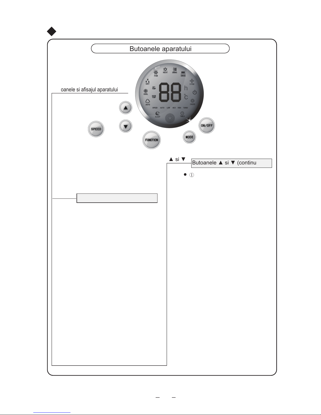
●
●
●
●
空调器功能键空调器功能键
Butoanele si afisajul aparatului
Butoanele aparatului
Prezentarea butoanelor si functiilor acestui aparat
▲ si▼
Butoanele ▲ si ▼
▲ si ▼
Butoanele ▲ si ▼ (continued )
①
②
9
Daca nu aveti activata nici o functie,
apasand butoanele sus/jos, veti putea
regla temperatura. La fiecare apasare a
butonului, temperatura va fi modificata cu
1°C. Optiunea de setare a temperaturii
este disponibila in intervalul 16°C-30°C. In
timpul functionarii in modul AUTO, butonul
SET TEMP nu va fi activat.
Butoanele sus/jos pot fi folosite pentru
alegerea functiei dorite.
Apasand simultan butoanele sus/jos,
pentru 3 secunde, veti activa blocarea
tastelor. La fiecare apasare, aparatul va
emite un avertisment sonor iar displayul
va afisa mesajul LC, intermitent, de 3 ori.
Pentru a debloca tastatura, repetati
procedeul de blocare.
La pornirea aparatului, daca veti
apasa de 2 ori in 20 de secunde,
butonul sus ▲, aparatul va intra in
modul de incalzire fortata. In timpul
functionarii, flapsul vertical se va regla
pe unghiul minim iar ventilatoarele
interioare si exterioare vor functiona la
viteza maxima. Toate simbolurile for fi
afisate pe display daca aparatul nu
detecteaza nici o eroare. In cazul in
care senzorul de temperatura
detecteaza o eroare, displayul va afisa
codul de eroare si va emite un
avertisment sonor si aparatul se va
opri automat in 5 minute de la
detectarea erorii.
Apasand butonul ▼, de 2 ori in 20
de secunde, veti activa functia de
racire fortata. Flapsul vertical se va
regla in unghiul minim, valva cu 4 cai
va fi inchisa si ventilatoarul interior si
cel exterior for functiona la viteza
maxima. Toate simbolurile for fi afisate
pe display daca aparatul nu detecteaza
nici o eroare. In cazul in care senzorul
de temperatura detecteaza o eroare,
displayul va afisa codul de eroare si va
emite un avertisment sonor si aparatul
se va opri automat in 5 minute de la
detectarea erorii.
Pasii ① si ② sunt disponibili doar
pentru testare.
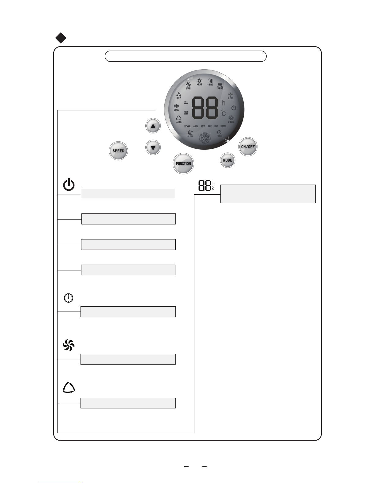
10
AUTO
●
●
In acest mod, doar ventilatorul va functiona,
compresorul fiind oprit.
●
In acest mod, functionarea se baza pe
schimbarile temperaturii interne detectate
de senzori.
Modul AUTO
Ventilator
●
●
●
●
●
●
●
●
●
空调器功能键
Butoanele si afisajul aparatului
Butoanele aparatului
Prezentarea butoanelor si functiilor acestui aparat
Temperatura interioara
Displayul
Display-ul porneste cand alimentati aparatul
cu energie electrica.
Setari
Temperatura setata va fi afisata
Simbolul TURBO va fi afisat atunci
cand aceasta functie este activata.
Turbo
Temperatura interioara va fi afisata.
TIMER
Temporizator
- Programati temporizatorul pentru pornirea/
oprirea automata a aparatului.
Temporizatorul poate fi ajustat doar cu
ajutorul telecomenzii.
FAN
Afisarea temperaturii incaperii/
temporizatorului/temperaturii setate
Puteti alege temperatura folosind
butonul de pe telecomanda.
Temporizatorul poate fi programat cu
ajutorul telecomenzii.
In cazul unei defectiuni, displayul v-a
afisa codul erorii.
In timpul functionarii normale, atunci
cand temperatura este setata prin
unitate sau telecomanda, setarea
aleasa v-a fi afisata pe display
(temperatura setata si temperatura
incaperii).
In timpul dezghetarii, simbolul H1 va fi
afisat. Cand ati activat si temporizatorul, display-ul va afisa informatiile in
urmatoarea ordine : temperatura
setata, temporizator, temperatura
incaperii.
In timpul dezghetarii (H1), fiecare
status va fi afisat, succesiv, timp de 5
secunde. Daca nici unul dintre
statusuri nu se schimba, doar
temperatura setata va fi afisata.
Temperatura incaperii va fi afisata
automat dupa pornire.

11
●
Modul Sleep
●
Oscilare verticala
●
Oscilare orizontala
●
Modul dezumidificare
●
Viteza ventilatorului va putea fi selectata
cu ajutorul telecomenzii, in urmatoarea
ordinge: AUTO, LOW, MED, HIGH sau
Turbo. Simbolul nivelului selectat va fi afisat.
Modul E-HEATER
●
X-FAN Display
●
●
●
Semnalizare mod racire
●
Simbolul COOL va fi afisat pe display
Simbolul modului incalzire
Simbolul Speed
●
Simbolul HEAT va fi afisat
Simbolul E-HEATER va fi afisat.
Cand acest mod este activat, simbolul
X-FAN va fi afisat.
空调器功能键空调器功能键
COOL
HEAT
SPEED
E-HEATER
X-FAN
SWING
DRY
SLEEP
SWING
Butoanele si afisajul aparatului
Butoanele aparatului
Prezentarea butoanelor si functiilor acestui aparat
Statusul oscilarii flapsului orizontal va
fi afisat.
Display-ul va afisa cele 2 statusuri :
ON (atunci cand este activata); OFF
(atunci cand este dezactivata)
Statusul oscilarii flapsului orizontal va
fi afisat.
Display-ul va afisa cele 2 statusuri :
ON (atunci cand este activata); OFF
(atunci cand este dezactivata)
Aceasta functie reduce umiditatea si
pastreaza temperatura incaperii
constanta.
Simbolul SLEEP v-a fi afisat dupa
activare. Aceasta functie nu poate fi
selectata decat cu ajutorul
telecomenzii.

12
FAN
AUTO
OPER
HEALTH
AIR
FILTER
TURBO
ON/OFF
X-FAN
HOUR
HUMIDITY
ON/OFF
MODE
FAN
X-FAN
TURBO
TEMP
TIMER
SLEEP
LIGHT
2
11
7
10
13
9
43
12
8
6
14
5
1
Apasati acest buton pentru a
porni/opri aparatul.
ON/OFF
MODE
+
-
Apasati acest buton pentru a va
alege modul de functionare
(AUTO/COOL/DRY/FAN/HEAT)
: Apasati acest buton pentru a creste
temperatura setata.
: Apasati acest buton pentru a
scadea temperatura setata.
FA
HEALTH SAVE
N
Apasati acest buton pentru a regla
oscilarea verticala a flapsurilor
Apasati butonul Light pentru porni/opri
iluminarea telecomenzii.
TIMER
X-FAN
(pagina 15)
(pagina 15)
TEMP (pagina 15)
TURBO (pagina 15)
SLEEP (pagina 16)
LIGHT
Apasati acest buton pentru a selecta
viteza ventilatorului.
Apasati acest buton pentru a programa
temporizatorul de pornire/oprire
.
1
2
Apasati acest buton pentru a selecta
modul Health
7
4
3
5
6
Apasati acest buton pentru a regla
oscilarea orizontala a flapsurilor.
Buton setare temperatura
8
11
9
10
12
13
14
Utilizarea telecomenzii

Utilizarea telecomenzii
15
20
21
23
24
16
17
18
FAN
AUTO
OPER
HEALTH
AIR
FILTER
TURBO
ON/OFF
X-FAN
HOUR
HUMIDITY
191520
18
16
17
21
22
23
24
13
22
19
Simbolul MODE
Atunci cand butonul MODE este
apasat, display-ul va afisa modul
activ
(AUTO) (COOL),
(DRY), (FAN) sau (HEAT doar pentru modelele cu pompa
de caldura)
Blocarea tastaturii
simbolul este afisat atunci cand
apasati simultan butoanele + si -.
Apasati inca odata butoanele
pentru a debloca tastatura.
Simbolul functiei LIGHT
Simbolul (light symbol) este afisat
atunci cand apasati butonul LIGHT.
Apasand inca o data butonul
LIGHT veti putea dezactiva lumina
si simbolul va disparea.
Sleep:
Simbolul este afisat atunci cand
apasati butonul SLEEP. Daca
apasati inca o data acest buton,
simbolul va disparea de pe display.
Simbolul TEMP :
Apasand butonul TEMP, ecranul va
afisa simbolul - temperatura
setata, pentru temperatura
interioara si pentru temperatura
exterioara.
Simbol Oscilare verticala:
Simboul este afisat atunci cand
apasati butonul corespondent.
Apasati inca odata butonul pentru a
dezactiva oscilarea.
Simbol Oscilare orizontala:
Simboul este afisat atunci cand
apasati butonul corespondent.
Apasati inca odata butonul pentru a
dezactiva oscilarea.
Simbolul pentru setarea orei
temporizatorului.
Dupa ce apasati butonul TIMER,
butonul simbolul On sau Off va fi
semnalizat intermitent.
Afisajul digital:
Acest display va afisa temperatura
setata. In timpul functionarii in
modul SAVE, ecranul va afisa
mesajul "SE". In timpul dezghetarii,
ecranul va afisa mesajul "H1".
Viteza ventilator:
Apasati butonul FAN pentru a va
alege viteza de functionare a
ventilatorului, in urmatoarea ordine
(AUTO-LOW-MED-HIGH).
Alegerea dumneavoastra va fi
afisata pe display, in afara de
viteza AUTO
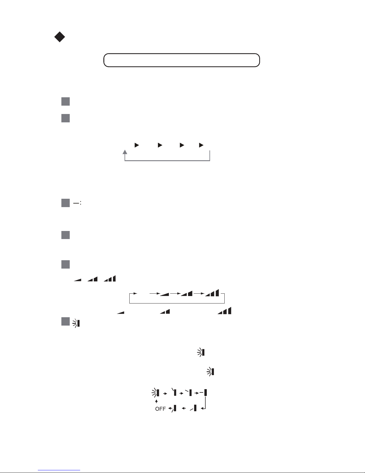
Prezentarea telecomenzii
+ :
FAN :
1
2
4
3
5
Utilizarea telecomenzii
-14-
AUTO
COOL
DRY
FAN HE
AT
*
Nota: mod disponibil doar la modelele cu functie de incalzire.
,
,
Auto
Viteza scazuta
Viteza medie
Viteza crescuta
:
6
●
●
●
●
Nota: Aceasta prezentare se refera la modelul generic de telecomanda, utilizabila la
aparatele de aer conditionat cu multiple functii. Unele functii nu sunt disponibile la
anumite modele si, atunci cand veti apasa butonul corespondent unei functii indisponibile, statusul de functionare a aparatului nu se va schimba.
ON/OFF:
Apasati acest buton pentru a porni/opri aparatul.
MODE:
Apasand acest buton, veti putea elege modul de functionare a aparatului, in ordinea de
mai jos:
La pornire, aparatul va functiona automat in modul AUTO. In acest mod, temperatura
setata nu va fi afisata pe display si unitatea va selecta automat conditiile de functionare, in functie de temperatura incaperii.
Apasati acest buton pentru a scadea temperatura setata. Daca veti tine butonul
apasat pentru 2 secunde, temperatura va scadea rapid. In modul AUTO, ajustarea
temperaturii nu este posibila.
Apasati acest buton pentru a creste temperatura setata. Daca veti tine butonul apasat
pentru 2 secunde, temperatura va creste rapid. In modul AUTO, ajustarea temperaturii
nu este posibila.
Apasand acest buton, veti putea regla viteza ventilatorului, conform ordinii de mai jos:
Apasati acest buton pentru a porni/opri oscilarea verticala. Telecomanda functioneaza
automat in modul de oscilare simpla.
Cand aparatul este oprit, apasati butonul + si , pentru a schimba modul de oscilare
(simpla sau statica). Simbolul va fi afisat intermitent timp de 2 secunde.
In timpul oscilarii simple, daca veti apasa butonul , unghiul flapsului vertical se va
schima conform schitei de mai jos:
Daca unitatea este oprita in timpul schimbarii unghiului, flapsul se va opri in pozitia in
care se afla in acel moment.

10
HEALTH SAVE:
7
11
9
12
15
:
8
Utilizarea telecomenzii
●
●
●
●
X-FAN:
Apasand butonul X-FAN, cand modul COOL sau DRY este activat, simbolul X-FAN va
fi afisat pe display. Compresorul se va opri, ventilatorul continuand sa functioneze timp
de 10 minute, pentru a usca unitatea interioara.
La pornire, functia X-FAN este inactiva. Aceasta functie nu este disponibila in timpul
functionarii in modul AUTO, FAN si HEAT.
TEMP:
Apasand acest buton, puteti alege intre afisarea temperaturii setate sau a temperaturii
incaperii. Cand aparatul este pornit, temperatura afisata va fi cea setata. Atunci cand
se schimba statusul, temperatura interioara va fi afisata timp de 5 secunde.
TIMER:
Cand aparatul este pornit, apasarea butonul TIMER va programa temporizatorul pentru
oprire. Mesajul HOUR OFF va fi afisat.
Cand aparatul este oprit, apasarea butonului TIMER va programa temporizatorul
pentru pornire si mesajul HOUR ON va fi afisat. Veti putea regla ora folosindu-va de
butoanele "+" "-". Tinand apasat unul din butoane, schimbarile se vor face rapid
(interval 0.5-24H). Pentru a confirma selectia, apasati butonul TIMER. Simbolul HOUR
ON/OFF va disparea. Daca nu apsati butonul TIMER timp de 5 secunde de la selectie,
programarea va fi anulata.
TURBO:
Apasati acest buton pentru a activa/dezactiva functia TURBO, ce permite atingerea
temperaturii setate in cel mai scurt timp. In modul COOL, unitatea va evacua aerul cu
la viteza cea mai mare a ventilatorului. Pentru modul HEAT, procedeul este acelasi
(modul HEAT este disponibil doar la aparatele cu functie de incalzire).
Apasati butonul HEALTH pentru a activa functia HEALTH.
Apasand butonul SAVE, aparatul va activa functia SAVE si mesajul va fi afisat pe
display. Pentru a anula functia, apasati inca odata butonul SAVE.
Cand modul SAVE este activat, temperatura si viteza ventilatorului nu pot fi ajustate.
Apasati acest buton pentru a porni/opri oscilarea orizontala. Telecomanda functioneaza
automat in modul de oscilare simpla.
Cand aparatul este oprit, apasati butonul + si , pentru a schimba modul de oscilare
(simpla sau statica). Simbolul va fi afisat intermitent timp de 2 secunde.
In timpul oscilarii simple, daca veti apasa butonul , unghiul flapsului orizontall se va
schima conform schitei de mai jos:
Daca aparatul este oprit in timpul oscilarii, flapsul se va opri in unghiul in care se afla
la momentul opririi

13
14
16
Schimbarea bateriei
★
●
●
●
●
●
3
2
Utilizarea telecomenzii
15
16
1. Inlaturati capacul bateriilor (conform imaginii alaturate).
2. Scoateti bateriile descarcate.
3. Inlocuiti cu 2 baterii noi AAA 1.5V, respectand polaritatea.
4. Acoperiti bateriile folosind capacul.
Note:
Atunci cand inlocuiti bateriile, nu folositi alte baterii descarcate sau un alt tip
de baterie, pericol de defectare a aparatului.
Daca nu veti folosi telecomanda pentru o perioada lunga de timp, scoateti
bateriile.
Folositi telecomanda in raza de actiune a acesteia.
Mentineti telecomanda la o distanta de cel putin 1 metru, fata de TV sau linii
audio stereo.
Daca telecomanda nu functioneaza, scoateti bateriile pentru 30 de secunde
si reintroduceti-le. Daca telecomanda continua sa nu functioneze, inlocuiti
bateriile.
SLEEP :
Apasati acest buton pentru a activa functia SLEEP. Pentru dezactivarea functiei,
apasati din nou butonul. Aceasta functie este disponibila in modurile COOL, HEAT
(doar la aparatele cu functie de incalzire) sau DRY.
LIGHT:
Pentru a porni sau opri iluminatul displayului, apasati butonul LIGHT. Cand lumina
este pornita, simbolul este afisat. Cand opriti lumina, simbolul va disparea.
Blocarea tastaturii cu ajutorul butoanelor "+" si "-".
Apasati simultan butoanele "+" si "-" pentru a bloca tastatura. Simbolul va fi
afisat atunci cand tastatura este blocata. In timp ce tastatura este blocata, atunci
cand apasati oricare dintre butoane, simbolul va fi afisat intermitent timp de 3
secunde.
Combinarea butoanelor MODE si "-" pentru a alege intre Celsius si Fahrenheit.
Cand unitatea este oprita, apasand cele 2 butoane simultan, veti putea schimba
afisajul din °C in °F

Oscilarea verticala
,
Fig.5
Fig.4
Flaps de ghidaj
(in dreptat in jos)
sau
Flaps ghidaj
(indreptat in sus)
Flaps ghidaj
Ajustarea fluxului de aer
sau
Fig.3
17
NOTE:
Puteti selecta oscilarea verticala apasand butoanale
Sus/Jos de pe telecomanda sau butonul FUNC, pe care il
puteti gasi pe unitatea interioara. Puteti folosi aceste
butoane pentru a alege oscilarea automata sau sa va
alegeti dumneavoastra unghiul de evacuare a aerului.
Daca ventilatorul unitatii interioare este in functiune, folositi
butoanele sus/jos de pe telecomanda pentru a regla modul
de oscilare.
Alegeti modul de oscilare folosind butoanele sus/jos de pe
telecomanda.
Daca dezactivati functia de oscilare, simbolurile de
identificare nu vor mai fi afisate pe display.
Pentru modurile de racire/dezumidificare, fluxul de aer
trebuie indreptat in sus sau frontal (imaginea 4).
La pornirea aparatului, puteti directiona fluxul de aer in jos
pentru o racire rapida insa nu pentru mult timp, pentru a a
sigura o buna circulatie a aerului in incapere.
Fluxul de aer trebuie directionat in jos doar pe modul
incalzire (imaginea 5).

Oscilarea orizontala
Fig.6
Buton oscilare orizontala
Buton oscilare verticala
Ajustarea fluxului de aer
18
Butoanele de selectare a oscilarii orizontale, pot fi folosite
pentru a putea controla fluxul de aer. Puteti folosi butoanele
de pe telecomanda sau butonul FUNC de pe unitatea
interioara, pentru a ghida flapsul vertical si a-l opri la un
anumit unghi.
Daca ventilatorul functioneaza, folositi butoanele de pe
telecomanda. Consultati manualul de utilizare a telecomenzii.
Folositi butoanele stanga/dreapta de pe telecomanda pentru
a selecta unghiul si apasati butoanele sus/jos ▼/▲, pentru a
activa/dezactiva functia.
La dezactivarea functiei, simbolurile de indentificare vor
disparea de pe display. Simbolurile vor fi reafisate atunci
cand selectati alte functii.
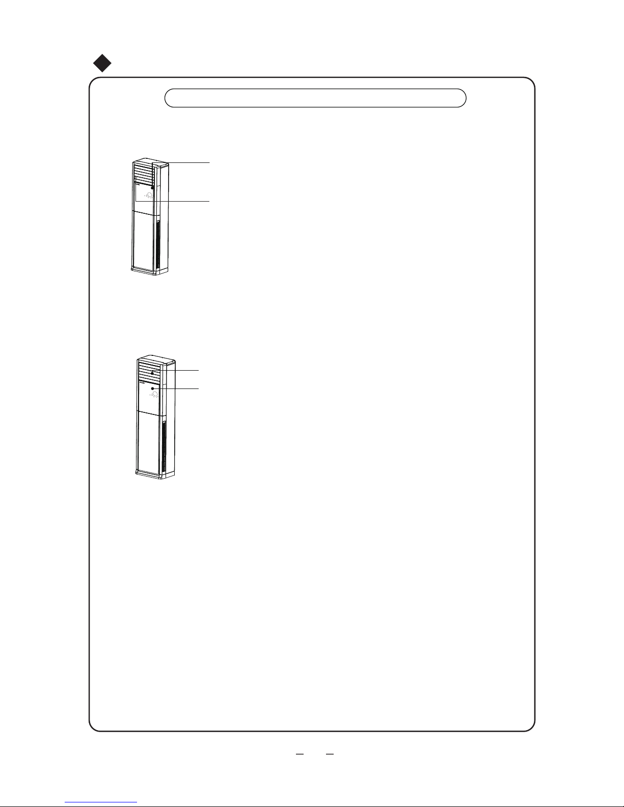
Operarea capacului glisant
La inceputul operatiunii
Instructiuni de folosire a functiilor speciale
19
1. Cand unitatea interioara este pornita, capacul va glisa
automat in jos, sub panoul frontal.
2. Cand capacul glisant este deschis, flapsul vertical si
ventilatorul vor porni.
La sfarsitul operatiunii
1. Cand unitatea interioara se opreste, flapsul vertical se va
opri in unghiul setat.
2. Atunci cand flapsul se opreste, capacul se va inchide
automat.
Nota:
1. Nu ajustati manual capacul glisant;
2. In cazul unei pene de curent, capacul glisant v-a ramane in pozitia in care se afla la
momentul penei. Cand alimentarea cu energie electrica se reia, capacul se va
inchide automat.
3. In cazul unei defectiuni, display-ul va afisa mesajul FC. Restartati aparatul si, daca
mesajul continua sa fie afisat, sunati departamentul de service.
4. Daca aparatul este pornit in modul de racire, pe capacul glisant vor aparea picaturi
de apa. Acesta este un fenomen normal.

①
②
③
Curatenie si mentenanta
Atentie
Curatati unitatea
Fig.7
Dry the cloth
before cleaning
Curatati filtrul o data la 2 saptamani
Fig.8
①
②
20
1. Opriti aparatul si scoateti-l din priza inainte de a-l curata. Pericol de electrocutare.
2. Nu stropiti unitatile interioare sau exterioara cu apa. Pericol de electrocutare.
3. Nu folositi lichide volatile pentru curatare (diluant, benzina). Pericol de defectare.
Stergeti unitatile cu o carpa uscata sau umezita putin.
Opriti aparatul inainte de a incepe.
Scoateti din priza inainte de a incepe.
Folositi o carpa fina pentru curatare.
Daca unitatea este foarte murdara, puteti umezi carpa in
apa calduta (sub 40 de grade celsius). Stoarceti bine
carpa. (imaginea 7)
Nu stropiti unitatile cu apa.
Puteti cauza defectarea placii de baza. (imaginea 7)
Demontarea filtrului de aer.
Procedand ca in imaginea alaturata(8), scoateti capacul
decorativ (1), desurubati panoul de geam si suruburile
filtrului. Scoateti filtrul de aer conform imaginii.
Curatarea filtrului
Puteti folosi aspiratorul sau apa calduta cu detergent delicat.
Dupa ce filtrul s-a uscat, il puteti reintroduce in aparat,
conform imaginii 8.
NOTA: Nu uscati filtrul prin expunerea directa la lumina
solara. Nu uscati filtrul plasand-ul pe surse de caldura.

Verificari prealabile
Mentenanta
①
②
③
④
①
②
③
④
Curatenie si mentenanta
21
Opriti aparatul
Curatati filtrul de aer si ambele unitati (interioara si exterioara).
Inlaturati obiectele care obstructioneaza unitatea exterioara si curatati-o.
In cazul aparitiei ruginei, vopsiti acea parte pentru a preveni extinderea
suprafetei ruginite.
Asigurati-va ca gurile de admisie/evacuare aer nu sunt obturate.
Asigurati-va ca impamantarea este realizata corect.
Verificati daca bateriile telecomenzii au fost schimbate.
Verivicati integritatea consolelor unitatii exterioare. Daca
acestea sunt defecte, contactati departamentul de service.

●
Depanarea
ATENTIE
Situatie
Solutie posibila
Waiting
22
Dupa ce ati oprit aparatul, in cazul in care
doriti sa il reporniti imediat, va trebui sa
asteptati 3 minute.
Acest fenomen poate aparea datorita unui
filtru murdar.
Curatati filtrul si daca problema persista,
notificati departamentul de service.
Aparatul nu porneste imediat
dupa ce a fost oprit.
Nu reparati aparatul de unul singur. Pericol de incendiu sau electrocutare.
Inainte de a notifica departamentul de service, faceti verificarile de mai jos. Puteti
economisii timp si bani.
Mirosuri ciudate dupa ce
aparatul a fost pornit.
Aceste sunete pot aparea atat in timpul
functionarii compresorului cat si cand acesta
este oprit. Este un fenomen normal si este
produs de agentul frigorific care curge prin
instalatie.
Cand unitatea interioara si umiditatea
incaperii sunt crescute, acest fenomen
poate aparea datorita racirii rapide a
camerei. Dupa o perioada, aburul va
disparea.
In timpul functionarii se aude
un sunet ca de apa
In timpul functionarii in modul
racire, aparatul produce
ceata/aburi.
Acest fenomen este cauzat de usoara
deformare a plasticului datorita schimbarilor
de temperatura.
Aparatul produce scartaituri la
pornire sau oprire.
 Loading...