

INVENTOR O3MVI32-09WiFiR, O3MVO32-09O3MVI32-12WiFiR, O3MVO32-24, O3MVO32-12O3MVI32-18WiFiR, O3MVO32-18O3MVI32-24WiFiR Service Manual
• SERVICE MANUAL
ENGLISH
WALL MOUNTED UNIT
AIR CONDITIONING SYSTEMS
MODELS:
O3MVI32-09WiFiR/O3MVO32-09
O3MVI32-12WiFiR/O3MVO32-12
O3MVI32-18WiFiR/O3MVO32-18
O3MVI32-24WiFiR/O3MVO32-24


Table of Contents
Page
1. Safety Precautions ........................................................................................ 1
1. Precautions
2. Information servicing
2. Specifications ................................................................................................ 7
1. Model Reference
2. Electrical Wiring Diagrams
3. Product Features ........................................................................................... 13
1. Operation Modes and Functions
4. Maintenance and Disassembly .................................................................... 20
1. Maintenance
2. Disassembly
5. Troubleshooting ............................................................................................ 59
1. Safety Caution
2. General Troubleshooting
3. Error Diagnosis and Troubleshooting Without Error Code
4. Quick Maintenance by Error Code
5. Troubleshooting by Error Code
Appendix ............................................................................................................. 86
i) Temperature Sensor Resistance Value Table for T1,T2,T3 and T4 (°C – K)
ii) Temperature Sensor Resistance Value Table for TP (°C – K)
iii) Pressure On Service Port
Caution: Risk of fire/flammable material


Contents
1. Precautions .............................................................................................................2
2. Information servicing ............................................................................................3
Safety Precautions

Safety
Precautions
Page 2
1. Precautions
To prevent personal injury, or property or unit damage,
adhere to all precautionary measures and instructions
outlined in this manual. Before servicing a unit, refer to this
service manual and its relevant sections.
Failure to adhere to all precautionary measures listed in this
section may result in personal injury, damage to the unit or
to property, or in extreme cases, death.
WARNING indicates a potentially hazardous
situation which if not avoided could result in serious
personal injury, or death.
CAUTION indicates a potentially hazardous situation
which if not avoided could result in minor or
moderate personal injury, or unit damage.
1.1 In case of Accidents or Emergency
WARNING
•• If a gas leak is suspected, immediately turn off the
gas and ventilate the area if a gas leak is suspected
before turning the unit on.
•• If strange sounds or smoke is detected from the unit,
turn the breaker off and disconnect the power supply
cable.
•• If the unit comes into contact with liquid, contact an
authorized service center.
•• If liquid from the batteries makes contact with skin or
clothing, immediately rinse or wash the area well with
clean water.
•• Do not insert hands or other objects into the air inlet
or outlet while the unit is plugged in.
•• Do not operate the unit with wet hands.
•• Do not use a remote controller that has previously
been exposed to battery damage or battery leakage.
CAUTION
•• Clean and ventilate the unit at regular intervals when
operating it near a stove or near similar devices.
•• Do not use the unit during severe weather conditions.
If possible, remove the product from the window
before such occurrences.
1.2 Pre-Installation and Installation
WARNING
•• Use this unit only on a dedicated circuit.
•• Damage to the installation area could cause the unit
to fall, potentially resulting in personal injury, property damage, or product failure.
•• Only qualified personnel should disassemble, install,
remove, or repair the unit.
•• Only a qualified electrician should perform electri-
cal work. For more information, contact your dealer,
seller, or an authorized service center.
CAUTION
•• While unpacking be careful of sharp edges around
the unit as well as the edges of the fins on the condenser and evaporator.
1.3 Operation and Maintenance
WARNING
•• Do not use defective or under-rated circuit breakers.
•• Ensure the unit is properly grounded and that a
dedicated circuit and breaker are installed.
•• Do not modify or extend the power cable. Ensure
the power cable is secure and not damaged during
operation.
•• Do not unplug the power supply plug during
operation.
•• Do not store or use flammable materials near the
unit.
•• Do not open the inlet grill of the unit during
operation.
•• Do not touch the electrostatic filter if the unit is
equipped with one.
•• Do not block the inlet or outlet of air flow to the unit.
•• Do not use harsh detergents, solvents, or similar items
to clean the unit. Use a soft cloth for cleaning.
•• Do not touch the metal parts of the unit when
removing the air filter as they are very sharp.
•• Do not step on or place anything on the unit or
outdoor units.
•• Do not drink water drained from the unit
•• Avoid direct skin contact with water drained from the
unit.
•• Use a firm stool or step ladder according to
manufacturer procedures when cleaning or
maintaining the unit.
CAUTION
•• Do not install or operate the unit for an extended
period of time in areas of high humidity or in an
environment directly exposing it to sea wind or salt
spray.
•• Do not install the unit on a defective or damaged
installation stand, or in an unsecure location.
•• Ensure the unit is installed at a level position
•• Do not install the unit where noise or air discharge
created by the outdoor unit will negatively impact the
environment or nearby residences.
•• Do not expose skin directly to the air discharged by
the unit for prolonged periods of time.
•• Ensure the unit operates in areas water or other
liquids.
•• Ensure the drain hose is installed correctly to ensure
proper water drainage.
•• When lifting or transporting the unit, it is
recommended that two or more people are used for
this task.
•• When the unit is not to be used for an extended time,
disconnect the power supply or turn off the breaker.

Safety
Precautions
Page 3
2. Information servicing
2.1 Checks to the area
• Prior to beginning work on systems containing flammable
refrigerants, safety checks are necessary to ensure that the
risk of ignition is minimized.
• For repair to the refrigerating system, the following
precautions shall be complied with prior to conducting work
on the system.
2.2 Work procedure
• Work shall be undertaken under a controlled procedure so
as to minimise the risk of a flammable gas or vapour being
present while the work is being performed.
2.3 Work procedure
• All maintenance staff and others working in the local area
shall be instructed on the nature of work being carried out.
• Work in confined spaces shall be avoided.
• The area around the work space shall be sectioned off.
Ensure that the conditions within the area have been made
safe by control of flammable material.
2.4 Checking for presence of refrigerant
• The area shall be checked with an appropriate refrigerant
detector prior to and during work, to ensure the technician
is aware of potentially flammable atmospheres.
• Ensure that the leak detection equipment being used is
suitable for use with flammable refrigerants, i.e. no sparking,
adequately sealed or intrinsically safe.
2.5 Presence of fire extinguisher
• If any hot work is to be conducted on the refrigeration
equipment or any associated parts, appropriate fire
extinguishing equipment shall be available to hand.
• Have a dry powder or CO2 fire extinguisher adjacent to the
charging area.
2.6 No ignition sources
• No person carrying out work in relation to a refrigeration
system which involves exposing any pipe work that contains
or has contained flammable refrigerant shall use any sources
of ignition in such a manner that it may lead to the risk of
fire or explosion.
• All possible ignition sources, including cigarette smoking,
should be kept sufficiently far away from the site of
installation, repairing, removing and disposal, during which
flammable refrigerant can possibly be released to the
surrounding space.
• Prior to work taking place, the area around the equipment
is to be surveyed to make sure that there are no flammable
hazards or ignition risks.
• NO SMOKING signs shall be displayed.
2.7 Ventilated area
• Ensure that the area is in the open or that it is adequately
ventilated before breaking into the
• system or conducting any hot work. A degree of ventilation
shall continue during the period
• that the work is carried out. The ventilation should safely
disperse any released refrigerant
• and preferably expel it externally into the atmosphere.
2.8 Checks to the refrigeration equipment
• Where electrical components are being changed,
they shall be fit for the purpose and to the correct
specification. At all times the manufacturer’s
maintenance and service guidelines shall be followed.
If in doubt consult the manufacturer’s technical
department for assistance. The following checks
shall be applied to installations using flammable
refrigerants:
• the charge size is in accordance with the room size
within which the refrigerant containing parts are
installed;
• the ventilation machinery and outlets are operating
adequately and are not obstructed;
• if an indirect refrigerating circuit is being used, the
secondary circuit shall be checked for the presence
of refrigerant; marking to the equipment continues
to be visible and legible.
• markings and signs that are illegible shall be
corrected;
• refrigeration pipe or components are installed in
a position where they are unlikely to be exposed
to any substance which may corrode refrigerant
containing components, unless the components
are constructed of materials which are inherently
resistant to being corroded or are suitably protected
against being so corroded.
2.9 Checks to electrical devices
• Repair and maintenance to electrical components shall
include initial safety checks and component inspection
procedures. If a fault exists that could compromise
safety, then no electrical supply shall be connected to
the circuit until it is satisfactorily dealt with. If the fault
cannot be corrected immediately but it is necessary to
continue operation, an adequate temporary solution
shall be used. This shall be reported to the owner of
the equipment so all parties are advised. Initial safety
checks shall include:

Safety
Precautions
Page 4
• that capacitors are discharged: this shall be done in
a safe manner to avoid possibility of sparking;
• that there no live electrical components and wiring
are exposed while charging, recovering or purging
the system;
• that there is continuity of earth bonding.
2.10 Repairs to sealed components
• During repairs to sealed components, all electrical
supplies shall be disconnected from the equipment
being worked upon prior to any removal of sealed
covers, etc. If it is absolutely necessary to have an
electrical supply to equipment during servicing, then
a permanently operating form of leak detection shall
be located at the most critical point to warn of a
potentially hazardous situation.
• Particular attention shall be paid to the following to
ensure that by working on electrical components, the
casing is not altered in such a way that the level of
protection is affected. This shall include damage to
cables, excessive number of connections, terminals
not made to original specification, damage to seals,
incorrect fitting of glands, etc.
• Ensure that apparatus is mounted securely.
• Ensure that seals or sealing materials have not
degraded such that they no longer serve the
purpose of preventing the ingress of flammable
atmospheres. Replacement parts shall be in
accordance with the manufacturer’s specifications.
NOTE: The use of silicon sealant may inhibit the
effectiveness of some types of leak detection equipment.
Intrinsically safe components do not have to be isolated
prior to working on them.
2.11 Repair to intrinsically safe components
• Do not apply any permanent inductive or capacitance
loads to the circuit without ensuring that this will not
exceed the permissible voltage and current permitted
for the equipment in use. Intrinsically safe components
are the only types that can be worked on while live
in the presence of a flammable atmosphere. The test
apparatus shall be at the correct rating.
• Replace components only with parts specified by the
manufacturer. Other parts may result in the ignition of
refrigerant in the atmosphere from a leak.
2.12 Cabling
• Check that cabling will not be subject to wear,
corrosion, excessive pressure, vibration, sharp edges
or any other adverse environmental effects. The check
shall also take into account the effects of aging or
continual vibration from sources such as compressors
or fans.
2.13 Detection of flammable refrigerants
• Under no circumstances shall potential sources of
ignition be used in the searching for or detection of
refrigerant leaks. A halide torch (or any other detector
using a naked flame) shall not be used.
2.14 Leak detection methods
• The following leak detection methods are deemed
acceptable for systems containing flammable
refrigerants. Electronic leak detectors shall be used
to detect flammable refrigerants, but the sensitivity
may not be adequate, or may need re-calibration.
(Detection equipment shall be calibrated in a
refrigerant-free area.) Ensure that the detector is not
a potential source of ignition and is suitable for the
refrigerant used. Leak detection equipment shall be
set at a percentage of the LFL of the refrigerant and
shall be calibrated to the refrigerant employed and
the appropriate percentage of gas (25 % maximum)
is confirmed. Leak detection fluids are suitable for
use with most refrigerants but the use of detergents
containing chlorine shall be avoided as the chlorine
may react with the refrigerant and corrode the copper
pipe-work.
• If a leak is suspected, all naked flames shall be
removed or extinguished.
• If a leakage of refrigerant is found which requires
brazing, all of the refrigerant shall be recovered
from the system, or isolated (by means of shut off
valves) in a part of the systemremote from the leak.
Oxygen free nitrogen (OFN) shall then be purged
through the system both before and during the
brazing process.
2.15 Removal and evacuation
• When breaking into the refrigerant circuit to make
repairs or for any other purpose, conventional
procedures shall be used. However, it is important
that best practice is followed since flammability is a
consideration.
• The following procedure shall be adhered to:
• remove refrigerant;
• purge the circuit with inert gas;
• evacuate;
• purge again with inert gas;
• open the circuit by cutting or brazing.

Safety
Precautions
Page 5
• The refrigerant charge shall be recovered into the
correct recovery cylinders. The system shall be flushed
with OFN to render the unit safe. This process may
need to be repeated several times. Compressed air or
oxygen shall not be used for this task. Flushing shall
be achieved by breaking the vacuum in the system
with OFN and continuing to fill until the working
pressure is achieved, then venting to atmosphere, and
finally pulling down to a vacuum. This process shall
be repeated until no refrigerant is within the system.
When the final OFN charge is used, the system shall
be vented down to atmospheric pressure to enable
work to take place. This operation is absolutely vital if
brazing operations on the pipe-work are to take place.
• Ensure that the outlet for the vacuum pump is not
close to any ignition sources and there is ventilation
available.
2.16 Charging procedures
• In addition to conventional charging procedures, the
following requirements shall be followed:
• Ensure that contamination of different refrigerants
does not occur when using charging equipment.
Hoses or lines shall be as short as possible to
minimize the amount of refrigerant contained in
them.
• Cylinders shall be kept upright.
• Ensure that the refrigeration system is earthed prior
to charging the system with refrigerant.
• Label the system when charging is complete (if not
already).
• Extreme care shall be taken not to overfill the
refrigeration system.
• Prior to recharging the system it shall be pressure
tested with OFN. The system shall be leak tested on
completion of charging but prior to commissioning.
A follow up leak test shall be carried out prior to
leaving the site.
2.17 Decommissioning
Before carrying out this procedure, it is essential that the
technician is completely familiar with the equipment and
all its detail. It is recommended good practice that all
refrigerants are recovered safely. Prior to the task being
carried out, an oil and refrigerant sample shall be taken.
In case analysis is required prior to re-use of reclaimed
refrigerant. It is essential that electrical power is available
before the task is commenced.
• Become familiar with the equipment and its operation.
• Isolate system electrically.
• Before attempting the procedure ensure that:
• mechanical handling equipment is available, if
required, for handling refrigerant cylinders;
• all personal protective equipment is available and
being used correctly;
• the recovery process is supervised at all times by a
competent person;
• recovery equipment and cylinders conform to the
appropriate standards.
• Pump down refrigerant system, if possible.
• If a vacuum is not possible, make a manifold so that
refrigerant can be removed from various parts of the
system.
• Make sure that cylinder is situated on the scales before
recovery takes place.
• Start the recovery machine and operate in accordance
with manufacturer’s instructions.
• Do not overfill cylinders. (No more than 80 % volume
liquid charge).
• Do not exceed the maximum working pressure of the
cylinder, even temporarily.
• When the cylinders have been filled correctly and the
process completed, make sure that the cylinders and
the equipment are removed from site promptly and all
isolation valves on the equipment are closed off.
• Recovered refrigerant shall not be charged into
another refrigeration system unless it has been cleaned
and checked.
2.18 Labelling
• Equipment shall be labelled stating that it has been decommissioned and emptied of
• refrigerant. The label shall be dated and signed. Ensure
that there are labels on the equipment stating the
equipment contains flammable refrigerant.
2.19 Recovery
• When removing refrigerant from a system, either for
servicing or decommissioning, it is recommended good
practice that all refrigerants are removed safely.
• When transferring refrigerant into cylinders, ensure
that only appropriate refrigerant recovery cylinders
are employed. Ensure that the correct numbers of
cylinders for holding the total system charge are
available. All cylinders to be used are designated
for the recovered refrigerant and labelled for that
refrigerant (i.e. special cylinders for the recovery of
refrigerant). Cylinders shall be complete with pressure
relief valve and associated shut-off valves in good
working order.

Safety
Precautions
Page 6
• Empty recovery cylinders are evacuated and, if
possible, cooled before recovery occurs.
• The recovery equipment shall be in good working
order with a set of instructions concerning the
equipment that is at hand and shall be suitable for the
recovery of flammable refrigerants. In addition, a set
of calibrated weighing scales shall be available and in
good working order.
• Hoses shall be complete with leak-free disconnect
couplings and in good condition. Before using the
recovery machine, check that it is in satisfactory
working order, has been properly maintained and that
any associated electrical components are sealed to
prevent ignition in the event of a refrigerant release.
Consult manufacturer if in doubt.
• The recovered refrigerant shall be returned to the
refrigerant supplier in the correct recovery cylinder,
and the relevant Waste Transfer Note arranged. Do not
mix refrigerants in recovery units and especially not in
cylinders.
• If compressors or compressor oils are to be removed,
ensure that they have been evacuated to an
acceptable level to make certain that flammable
refrigerant does not remain within the lubricant.
The evacuation process shall be carried out prior to
returning the compressor to the suppliers. Only electric
heating to the compressor body shall be employed
to accelerate this process. When oil is drained from a
system, it shall be carried out safely.

Contents
1. Model Reference ....................................................................................................8
2. Electrical Wiring Diagrams ....................................................................................9
2.1 Indoor Unit ....................................................................................................9
2.2 Outdoor Unit ...............................................................................................11
Specifications
Specifications
Page 8
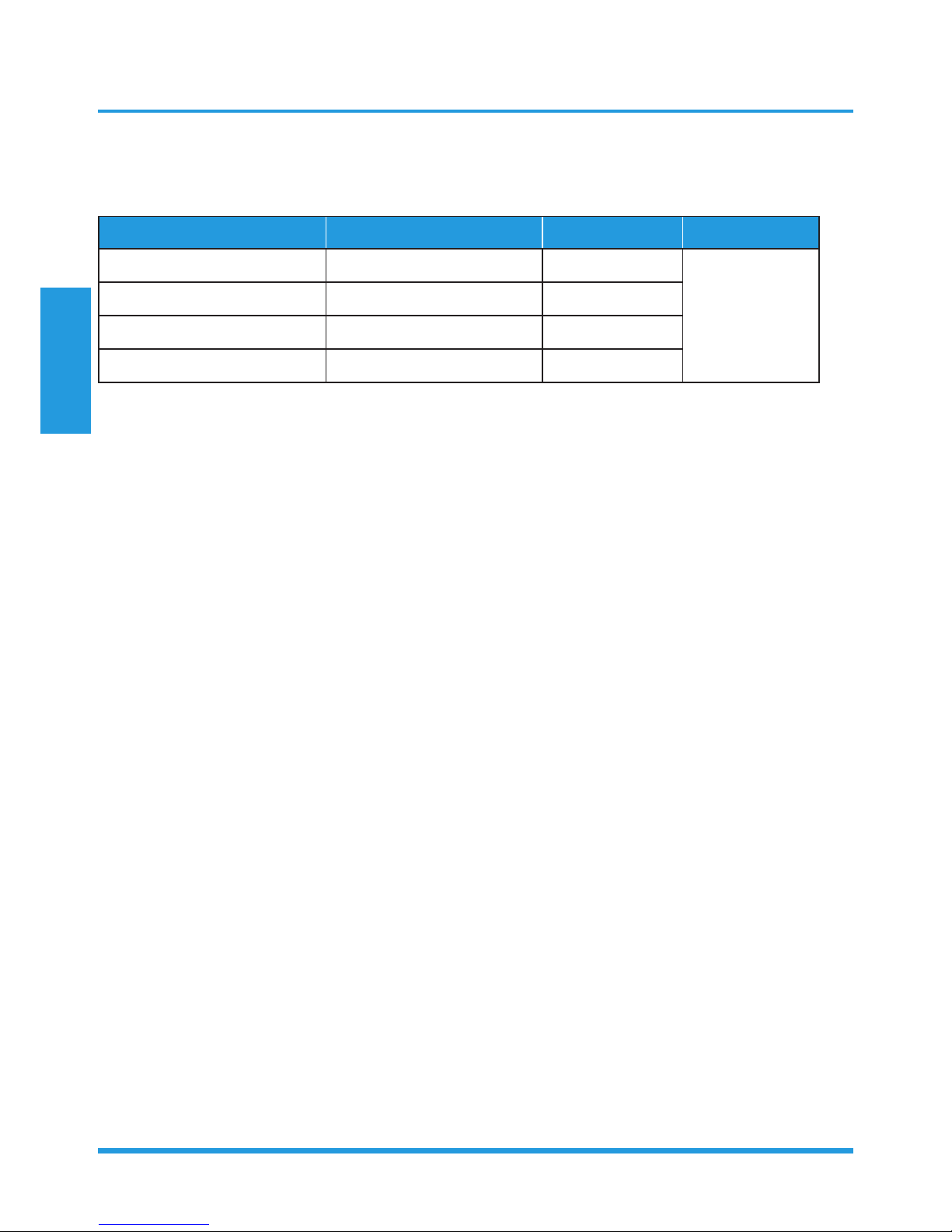
1. Model Reference
Refer to the following table to determine the specific indoor and outdoor unit model number of your purchased
equipment.
Indoor Unit Model Outdoor Unit Model Capacity (Btu) Power Supply
O3MVI32-09WiFiR O3MVO32-09
9k
220-240V~, 50Hz,
1Phase
O3MVI32-12WiFiR O3MVO32-12
12k
O3MVI32-24WiFiR O3MVO32-18
18k
O3MVI32-24WiFiR O3MVO32-24
24k

Specifications
Page 9
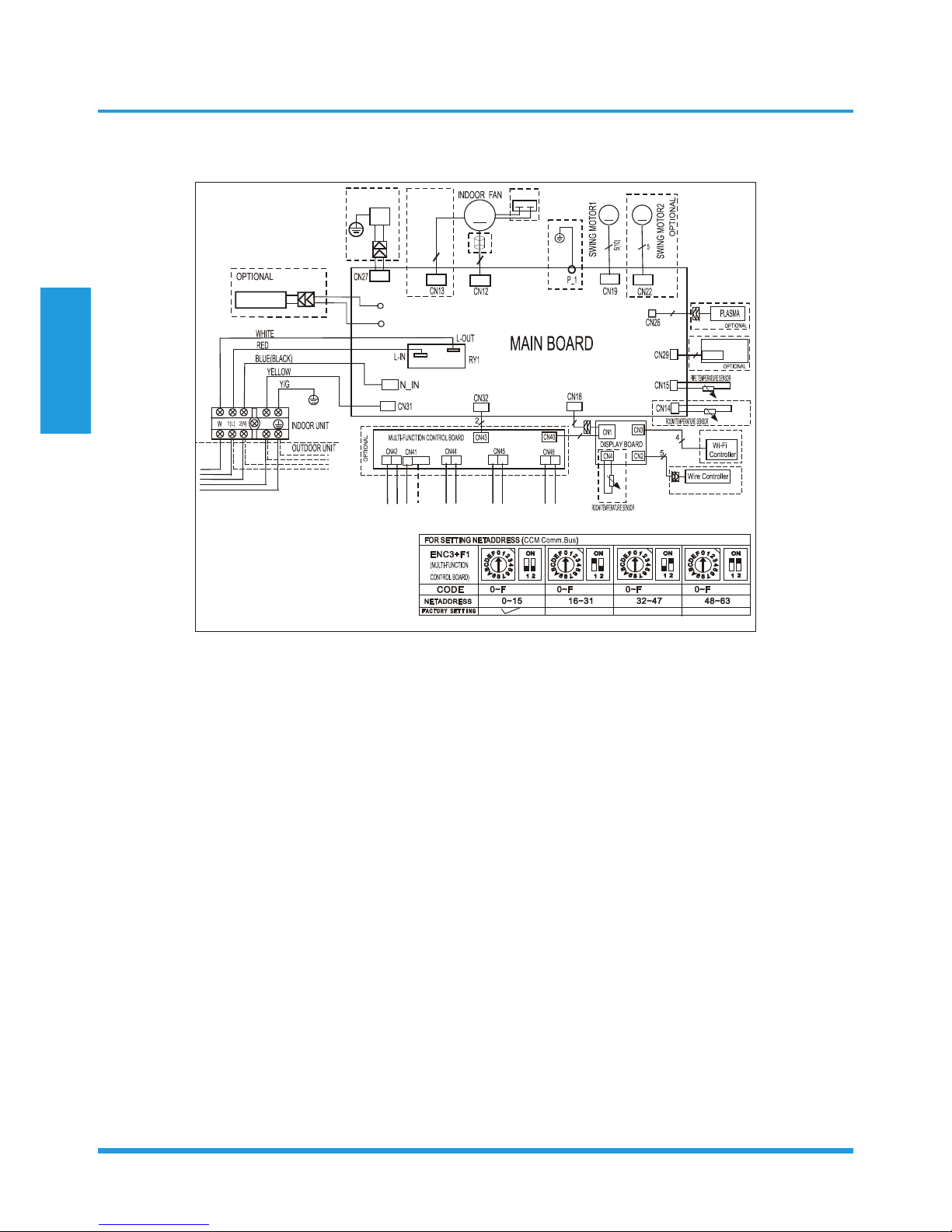
2. Electrical Wiring Diagrams
2.1 Indoor unit
Abbreviation Paraphrase
Y/G Yellow-Green Conductor
ION Positive and Negative Ion Generator
CAP Capacitor
PLASMA Electronic Dust Collector
L LIVE
N NEUTRAL
Heater The Electric Heating Belt of Indoor Unit
T1 Indoor Room Temperature
T2 Coil Temperature of Indoor Heat Exchanger Middle
Specifications
Page 10
O3MVI32-09WiFiR, O3MVI32-12WiFiR, O3MVI32-18WiFiR, O3MVI32-24WiFiR
INDOOR WIRING DIAGRAM
P1
P2
S
16022000020169
HEATER
OPTIONAL
Applicalbe for MONO unit with
1W standby control feature
Applicable for MULTI and
MONO unit without 1W
standby control feature
X Y E 12V/5V
HA HB
To CCM Comm.Bus or
485 Wire-controller
To Randomly
Connected
Wire-controller
To Remote Switch
To Remote Alarm
4
3
- - - - This symbol indicates the
element is optional,the actual
shape shall prevail.
M
M
M
5(3or2)
ION
OPTIONAL
Y/G
3
Applicable to
AC motor only
OPTIONAL
CAP
2
OPTIONAL
OPTIONAL
CN701
SWITCH BOARD
2
Specifications
Page 11
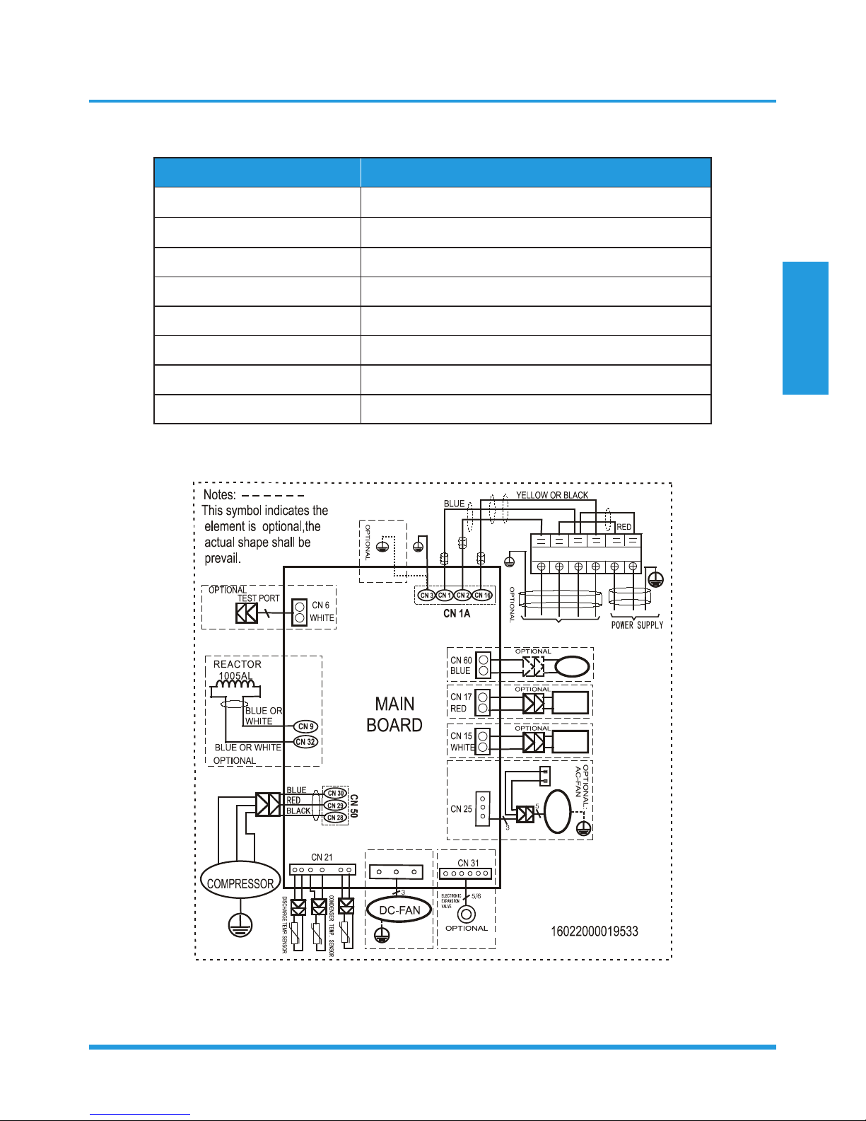
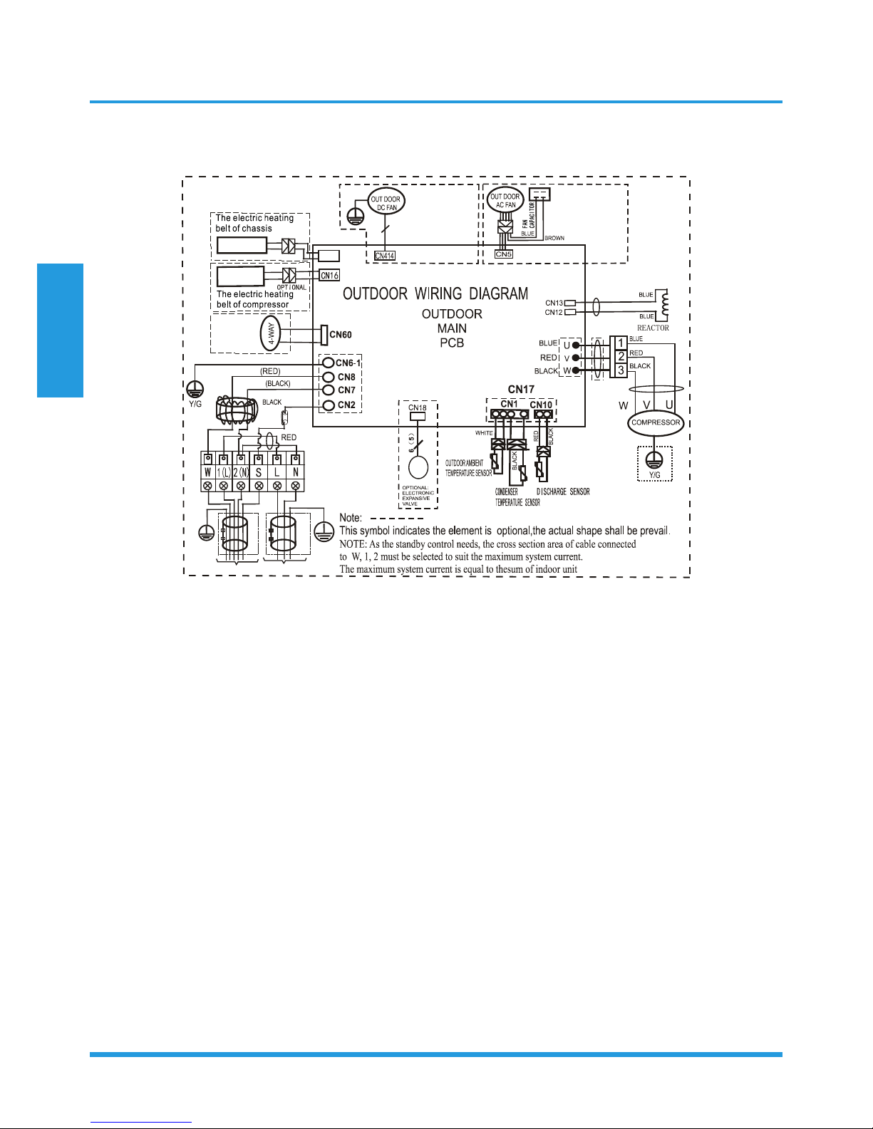
2.2 Outdoor Unit
Abbreviation Paraphrase
4-WAY Gas Valve Assembly/4-WAY VALVE
AC-FAN Alternating Current FAN
DC-FAN Direct Current FAN
CT1 AC Current Detector
COMP Compressor
L-PRO Low Pressure Switch
H-PRO High Pressure Switch
EEV Electronic Expansion Valve
O3MVO32-09, O3MVO32-12, O3MVO32-18
4-WAY
OPTIONAL:
DC-FAN
CN 7
AC-FAN
CAPACITOR
PAN
HEATER
CRANKCASE
HEAT ER
BROWN
I NDOOR UNI T
S
W
2(N)
L
N
BLUE OR BLACK
1(L)
Y/G
AMBIENT TEMP. SENSOR
Y/G
Y/G
Y/G
Y/G
Y/G
U
V
W
BLUE
RED
BLACK
Y/G
Specifications
Page 12
O3MVO32-24
BLAC
K(BLUE
)
OPTIONAL:
HEATER 2
H
E
A
TE
R
1
O
P
T
IO
N
A
L
CN4
BR
OWN
BLUE
16022000019069
()YELLOW
3
Applicable to
the units adopting
DC motor only
Applicable to
the units adopting
AC motor only
CN3
CN30
TO I NDOOR UNI T
POWER SUPPL Y
Y/G
O
PTI
O
NA
L
O
PTI
O
NAL

Contents
1. Operation Modes and Functions ........................................................................14
1.1 Abbreviation ................................................................................................14
1.2 Safety Features ............................................................................................14
1.3 Display Function ..........................................................................................14
1.4 Fan Mode ....................................................................................................15
1.5 Cooling Mode .............................................................................................15
1.6 Heating Mode .............................................................................................15
1.7 Auto-mode ..................................................................................................16
1.8 Drying Mode ...............................................................................................16
1.9 Forced Operation Function ..........................................................................16
1.10 Sleep Function .............................................................................................16
1.11 Auto-Restart Function ..................................................................................16
1.12 Refrigerant Leakage Detection .....................................................................17
1.13 8°C Heating(Optional) ................................................................................17
1.14 Self Clean(Optional) ....................................................................................17
1.15 Follow Me(Optional) ...................................................................................17
1.16 Silence(Optional) .......................................................................................17
1.17 Information Inquiry ......................................................................................17
Product Features
Product Features
Page 14
1. Operation Modes and Functions
1.1 Abbreviation
Unit element abbreviations
Abbreviation Element
T1 Indoor room temperature
T2 Coil temperature of evaporator
T3 Coil temperature of condenser
T4 Outdoor ambient temperature
TS Set temperature
TP Compressor discharge temperature
1.2 Safety Features
Compressor three-minute delay at restart
Compressor functions are delayed for up to one minute
upon the first startup of the unit, and are delayed for up
to three minutes upon subsequent unit restarts.
Zero crossing detection error protection
If AC can not detect zero crossing signal for 4 minutes or
the zero crossing signal time interval is not correct, the unit
will stop and the LED will display the failure. The correct
zero crossing signal time interval should be between
6-13ms.
Automatic shutoff based on discharge temperature
If the compressor discharge temperature exceeds 108°C
for a period of time, the compressor ceases operation.
Automatic shutoff based on fan speed
If the indoor fan speed registers below 300RPM for an
extended period of time, the unit ceases operation and the
corresponding error code is displayed on the indoor unit.
Inverter module protection
The inverter module has an automatic shutoff mechanism
based on the unit’s current, voltage, and temperature.
If automatic shutoff is initiated, the corresponding error
code is displayed on the indoor unit and the unit ceases
operation.
Indoor fan delayed operation
• When the unit starts, the louver is automatically
activated and the indoor fan will operate after a period
of 7 seconds.
• If the unit is in heating mode, the indoor fan is
regulated by the anti-cold wind function.
Compressor preheating
Preheating is automatically activated when T4 sensor is
lower than 3°C.
Sensor redundancy and automatic shutoff
• If one temperature sensor malfunctions, the air
conditioner continues operation and displays the
corresponding error code, allowing for emergency use.
• When more than one temperature sensor is
malfunctioning, the air conditioner ceases operation.
Refrigerant leakage detection
This function is active only when cooling mode is selected.
It will detect if the compressor is being damaged by
refrigerant leakage or by compressor overload. This is
measured using the coil temperature of evaporator T2
when the compressor is in operation.
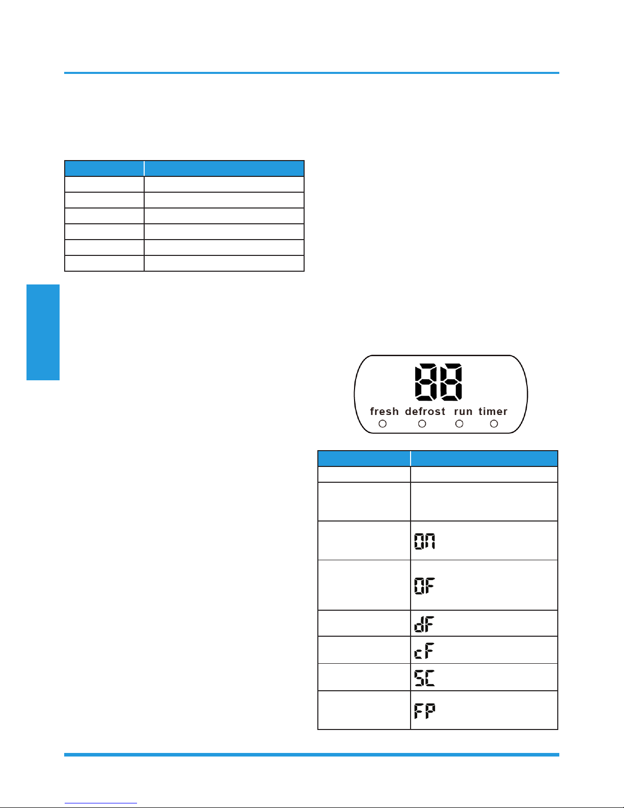
1.3 Display Function
Unit display functions
Function Display
Temperature Set temperature value
Temperature
(fan and Drying
mode)
Room temperature
Activation of Timer
ON, Fresh, Swing,
Turbo, or Silent
(3s)
Cancellation of
Timer OFF, Fresh,
Swing, Turbo, or
Silent
(3s)
Defrost
Warming in heating
mode
Self-clean (available
on select units only)
Heating in room
temperature
under 8°C

Product Features
Page 15
1.4 Fan Mode
When fan mode is activated:
• The outdoor fan and compressor are stopped.
• Temperature control is disabled and no temperature
setting is displayed.
• The indoor fan speed can be set to high, medium, low,
or auto.
• The louver operations are identical to those in cooling
mode.
• Auto fan: In fan-only mode, AC operates the same as
auto fan in cooling mode with the temperature set at
24°C.
1.5 Cooling Mode
1.5.1 Compressor Control
∆T means the temperature compensation.
• When T1-Ts < ∆T- 2 ℃, the compressor ceases
operation.
• When T1-Ts > ∆T+3℃, the compressor continues
operation.
• When the AC is operating in mute mode, the
compressor operates at a low frequency.
• When the current exceeds the preset value, the current
protection function activates and the compressor
ceases operation.
1.5.2 Indoor Fan Control
• In cooling mode, the indoor fan operates continuously.
The fan speed can be set to high, medium, low, or
auto.
• If the compressor ceases operations when the
configured temperature is reached, the indoor fan
motor operates at the minimum or configured speed.
1.5.3 Outdoor Fan Control
• The outdoor unit will be run at different fan speed
according to T4 and compressor frequency.
• For different outdoor units, the fan speeds are
different.
1.5.4 Condenser Temperature Protection
When condenser temperature is more than setting value,
the compressor ceases operations..
1.5.5 Evaporator Temperature Protection
When evaporator temperature drops below a configured
value, the compressor and outdoor fan cease operations.
1.6 Heating Mode
1.6.1 Compressor Control
∆T means the temperature compensation.
• When T1-Ts>-∆T, the compressor ceases operation.
• When T1-Ts<-∆T-1.5°C, the compressor continues
operation.
• When the AC is operating in mute mode, the
compressor operates at a low frequency.
• When the current exceeds the preset value, the current
protection function activates and the compressor
ceases operation.
1.6.2 Indoor Fan Control:
• When the compressor is on, the indoor fan can be
set to high/medium/low/auto. And the anti-cold wind
function has the priority.
• When indoor unit coil temp. is low, the anti-cold air
function will start and indoor fan motor will run at low
speed, the speed can’t be changed ,when the temp.
is lower than setting value, the indoor fan motor will
stop.
• When the indoor temp reaches the setting temp., the
compressor will stop, the indoor fan motor will run at
the minimum speed or setting speed.(The anti-cold air
function is valid).
1.6.3 Outdoor Fan Control:
• The outdoor unit will be run at different fan speed
according to T4 and compressor frequency.
• For different outdoor units, the fan speeds are
different.
1.6.4 Defrosting mode
• The unit enters defrosting mode according to the
temperature value of T3 and T4 as well as the
compressor running time.
• In defrosting mode, the compressor continues to run,
the indoor and outdoor motor will cease operation,
the defrost light of the indoor unit will turn on, and
the “ ” symbol is displayed.
• If any one of the following conditions is satisfied,
defrosting ends and the machine switches to normal
heating mode:
• T3 rises above TCDE1°C.
• T3 maintained above TCDE2°C for 80 seconds.
• Unit runs for 15 minutes consecutively in defrosting
mode.
1.6.5 Evaporator Temperature Protection
When the evaporator temperature exceeds a preset
protection value, the compressor ceases operations.

Product Features
Page 16
1.7 Auto-mode
• This mode can be selected with the remote controller
and the setting temperature can be changed between
17°C~30°C.
• In auto mode, the machine selects cooling, heating, or
fan-only mode on the basis of ∆T (∆T =T1-Ts).
∆T Running mode
∆T>2℃ Cooling
-2℃≤∆T≤2℃ Fan-only
∆T<-2℃ Heating*
Heating*: In auto mode, cooling only models run the fan
• The louver operates same as in relevant mode.
• If the machine switches mode between heating and
cooling, the compressor will keep stopping for certain
time and then choose mode according to T1-Ts.
• If the setting temperature is modified, the machine will
choose running function again.
1.8 Drying mode
• Indoor fan speed is fixed at breeze and can’t be
changed. The louver angle is the same as in cooling
mode.
• All protections are active and the same as that in
cooling mode.
1.9 Forced operation function
• Forced cooling mode:
The compressor and outdoor fan continue to run and
the indoor fan runs at low speed. After running for 30
minutes, the AC will switch to auto mode with a preset
temperature of 24°C.
• Forced auto mode:
Forced auto mode operates the same as normal auto mode
with a preset temperature of 24°C.
• The unit exits forced operation when it receives the
following signals:
• Switch on
• Switch off
• Timer on
• Timer off
• Changes in:
• mode
• fan speed
• sleeping mode
• Follow me
1.10 Sleep function
• The sleep function is available in cooling, heating, or
auto mode.
• The operational process for sleep mode is as follows:
• When cooling, the temperature rises 1°C (to not
higher than 30°C) every hour. After 2 hours, the
temperature stops rising and the indoor fan is fixed
at low speed.
• When heating, the temperature decreases 1°C(to
not lower than 17°C) every hour. After 2 hours, the
temperature stops decreasing and the indoor fan is
fixed at low speed. Anti-cold wind function takes
priority.
• The operating time for sleep mode is 7 hours, after
which, the unit exits this mode and switches off.
• The timer setting is available in this mode.
1.11 Auto-Restart function
• The indoor unit has an auto-restart module that
allows the unit to restart automatically. The module
automatically stores the current settings (not including
the swing setting) and, in the case of a sudden power
failure, will restore those setting automatically within 3
minutes after power returns.
• If the unit was in forced cooling mode, it will run in
this mode for 30 minutes and turn to auto mode with
temperature set to 24°C.
• If there is a power failure while the unit is running, the
compressor starts 3 minutes after the unit restarts. If
the unit was already off before the power failure, the
compressor starts 1 minute after the unit restarts.
1.12 Refrigerant Leakage Detection
With this new technology, the display area will show “EC”
when the outdoor unit detects refrigerant leakage.
1.13 8°C Heating(Optional)
In heating mode, the temperature can be set to as low
as 8°C, preventing the indoor area from freezing if
unoccupied during severe cold weather.
1.14 Self clean(Optional)
• If you press “Self Clean” when the unit is in cooling or
drying mode:
• For cooling models, the indoor unit will run in low
fan mode for a certain time, then ceases operation.

Product Features
Page 17
• For heat pump models, the indoor unit will run in
fan-only mode, then low heat, and finally in fanonly mode.
• Self Clean keeps the indoor unit dry and prevents
mold growth.
1.15 Follow me(Optional)
• If you press “Follow Me” on the remote, the indoor
unit will beep. This indicates the follow me function is
active.
• Once active, the remote control will send a signal
every 3 minutes, with no beeps. The unit automatically
sets the temperature according to the measurements
from the remote control.
• The unit will only change modes if the information
from the remote control makes it necessary, not from
the unit’s temperature setting.
• If the unit does not receive a signal for 7 minutes or
you press “Follow Me,” the function turns off. The
unit regulates temperature based on its own sensor
and settings.
1.16 Silence (Optional)
Press “Silence” on the remote control to enable the
SILENCE function. While this function is active, the
compressor frequency is maintained at a lower level than
F2. The indoor unit will run at faint breeze, which reduces
noise to the lowest possible level.
1.17 Information Inquiry
• To enter information inquiry status, complete the
following procedure within ten seconds:
• Press LED 3 times.
• Press SWING 3 times.
• If you are successful, you will hear beeps for two
seconds.
• Use the LED and SWING buttons to cycle through
information displayed.
• Pressing LED will display the next code in the
sequence. Pressing SWING will show the previous.
• The following table shows information codes. The
screen will display this code for two seconds, then the
information for 25 seconds.

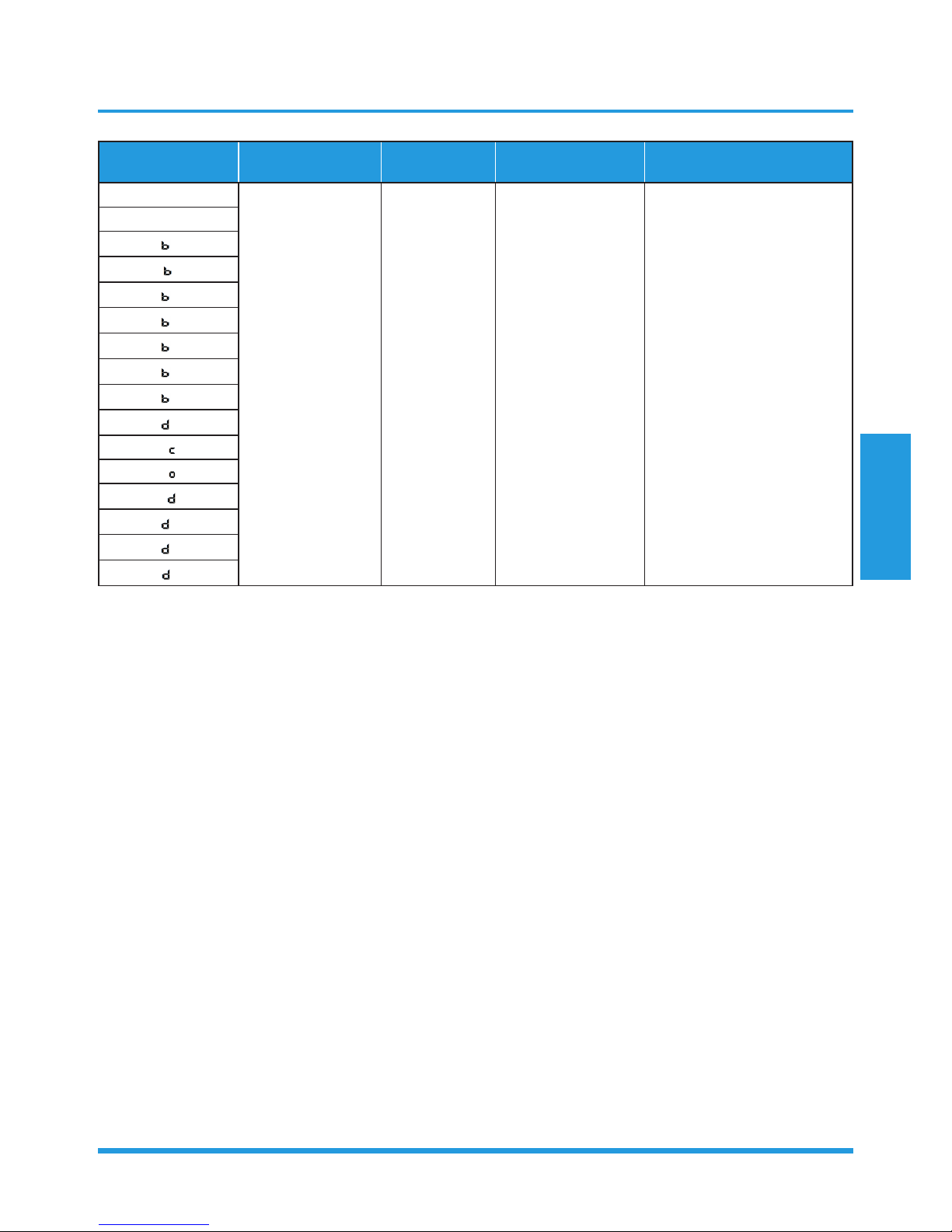
Product Features
Page 18
Displayed code Explanation
Displayed
value
Meaning Additional Notes
T1
T2
T3
T4
Tb
TP
TH
FT
Fr
Room temperature
-1F,-1E,-1d,-1c,1b,-1A
-19—99
A0,A1,…A9
b0,b1,…b9
c0,c1,…c9
d0,d1,…d9
E0,E1,…E9
F0,F1,…F9
-25,-24,-23,-22,
-21,-20
-19—99
100,101,…109
110,111,…119
120,121,…129
130,131,…139
140,141,…149
150,151,…159
1. All displayed temperatures
use actual values.
2. All temperatures are
displayed in °C regardless
of remote used.
3. T1, T2, T3, T4, and T2B
display ranges from -25 to
70 °C. TP display ranges
from -20 to 130 °C.
4. The frequency display
ranges from 0 to 159HZ.
5. If the actual values exceed
or fall short of the defined
range, the values closest
to the maximum and
minimum values will be
displayed.
Indoor coil
temperature
Outdoor coil
temperature
Ambient
temperature
Outlet temperature
of indoor coil
Discharge
temperature
Suction temperature
Targeted frequency
Actual frequency
IF
Indoor fan speed
0
1,2,3,4
14-FF
OFF
Low speed, Medium
speed, High speed,
Turbo.
Actual fan speed is
equal to the display
value converted to
decimal value and
multiplied by 10. This
is measured in RPM.
N/A
Used for some large capacity
motors.
Used for some small capacity
motors.
The display value is 14-FF
(hexadecimal). The
corresponding fan speed
ranges from 200 to 2550RPM.
OF
Outdoor fan speed
LA
EXV opening angle 0-FF
Actual EXV opening
value is equal to
the display value
converted to decimal
value and then
multiplied by 2.
-
CT
Compressor
continuous running
time
0-FF 0-255 minutes
If the actual value exceeds
or falls short of the defined
range, the value closest to the
maximum and minimum will
be displayed.
ST
Causes of
compressor stop
0-99
For a detailed
explanation, contact
technical support.
-
Product Features
Page 19
Displayed code Explanation
Displayed
value
Meaning Additional Notes
A0
Reserved
0-FF
2-28
5-20
5-25
- -
A1
0
1
2
3
4
5
6
L
A
U
T
A
5
T

Contents
1. Maintenance ........................................................................................................21
1.1 First Time Installation Check ........................................................................21
1.2 Refrigerant Recharge ...................................................................................23
1.3 Re-Installation .............................................................................................24
1.3.1 Indoor Unit ..................................................................................24
1.3.2 Outdoor Unit ...............................................................................26
2. Disassembly .........................................................................................................28
2.1 Indoor Unit ..................................................................................................28
2.2 Outdoor Unit ...............................................................................................40
Maintenance and Disassembly
Maintenance and
Disassembly
Page 21
1. Maintenance
1.1 First Time Installation Check
Air and moisture trapped in the refrigerant system affects
the performance of the air conditioner by:
• Increasing pressure in the system.
• Increasing the operating current.
• Decreasing the cooling or heating efficiency.
• Congesting the capillary tubing due to ice build-up in
the refrigerant circuit.
• Corroding the refrigerant system.
To prevent air and moisture from affecting the air
conditioner’s performance, the indoor unit, as well as the
pipes between the indoor and outdoor unit, must be be
leak tested and evacuated.
Leak test (soap water method)
Use a soft brush to apply soapy water or a neutral liquid
detergent onto the indoor unit connections and outdoor
unit connections. If there is gas leakage, bubbles will form
on the connection.
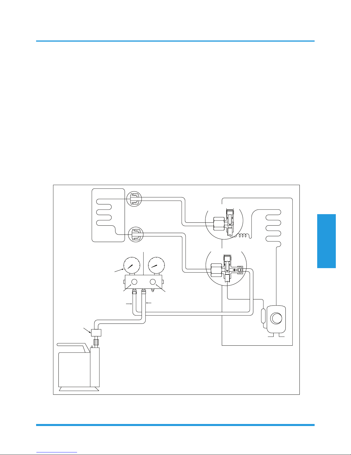
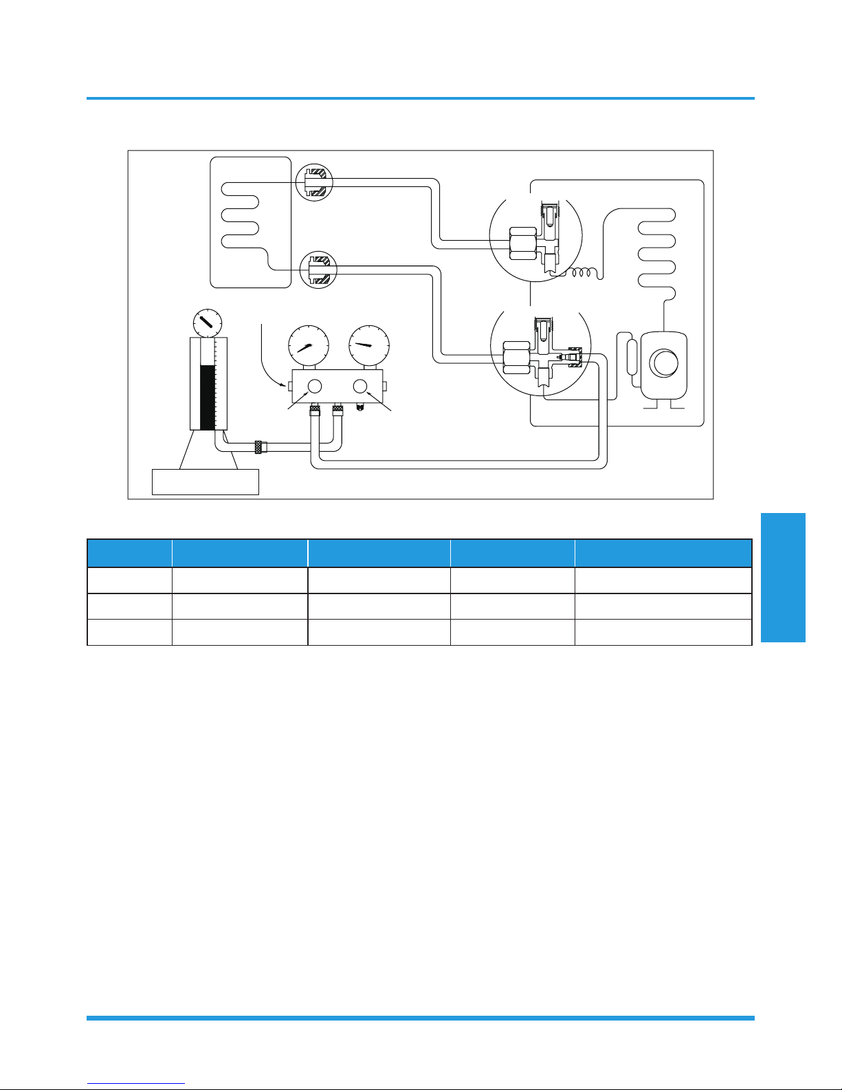
Air purging with vacuum pump
/TJUUX[TOZ
2OW[OJYOJK
-GYYOJK
:]U]G_\GR\K
:NXKK]G_\GR\K
5[ZJUUX[TOZ
)RUYK
)RUYK
3GTOLURJ\GR\K
36G
6XKYY[XK
MG[MK
.GTJRK2U
.GTJRK.O
)NGXMKNUYK
)NGXMKNUYK
<GI[[S
V[SV
<GI[[S
V[SV
)USVU[TJSKZKX
2U
.O

Maintenance and
Disassembly
Page 22
Procedure:
1. Tighten the flare nuts of the indoor and outdoor
units, and confirm that both the 2- and 3-way valves
are closed.
2. Connect the charge hose with the push pin of Handle
Lo to the gas service port of the 3-way valve.
3. Connect another charge hose to the vacuum pump.
4. Fully open the Handle Lo manifold valve.
5. Using the vacuum pump, evacuate the system for
30 minutes.
a. Check whether the compound meter indicates
-0.1 MPa (14.5 Psi).
• If the meter does not indicate -0.1 MPa
(14.5 Psi) after 30 minutes, continue
evacuating for an additional 20 minutes.
• If the pressure does not achieve -0.1 MPa
(14.5 Psi) after 50 minutes, check for leakage.
• If the pressure successfully reaches -0.1 MPa
(14.5 Psi), fully close the Handle Lo valve, then
cease vacuum pump operations.
b. Wait for 5 minutes then check whether the gauge
needle moves after turning off the vacuum pump.
If the gauge needle moves backward, check
wether there is gas leakage.
6. Loosen the flare nut of the 3-way valve for 6 or
7 seconds and then tighten the flare nut again.
a. Confirm the pressure display in the pressure
indicator is slightly higher than the atmospheric
pressure.
b. Remove the charge hose from the 3-way valve.
7. Fully open the 2- and 3-way valves and tighten the
cap of the 2- and 3-way valves.
Maintenance and
Disassembly
Page 23
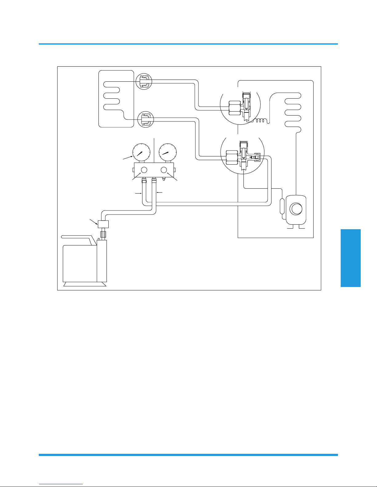
1.2 Refrigerant Recharge
/TJUUX[TOZ
2OW[OJYOJK
-GYYOJK
)NKIQ\GR\K
56+4
)259+
)NGXMOTM
:]U]G_\GR\K
:NXKK]G_\GR\K
5[ZJUUX[TOZ
5VKT
5VKT
2U
.O
+RKIZXUTOIYIGRK
I_ROTJKX
Prior to recharging the refrigerant, confirm the additional amount of refrigerant required using the following table:
Models Standard length Max. elevation Max. length Additional refrigerant
9k&12k 5m (16.4ft) 10m (32.8ft) 25m (82.0ft) 12g/m (0.13oz/ft)
18k 5m (16.4ft) 20m (65.6ft) 30m (98.4ft) 12g/m (0.13oz/ft)
24k 5m (16.4ft) 25m (82ft) 50m (164ft) 24g/m (0.26oz/ft)
Procedure:
1. Close both 2- and 3-way valves.
2. Slightly connect the Handle Lo charge hose to the
3-way service port.
3. Connect the charge hose to the valve at the bottom
of the cylinder.
4. If the refrigerant is R410A, invert the cylinder to
ensure a complete liquid charge.
5. Open the valve at the bottom of the cylinder for 5
seconds to purge the air in the charge hose, then fully
tighten the charge hose with push pin Handle Lo to
the service port of 3-way valve..
6. Place the charging cylinder onto an electronic scale
and record the starting weight.
7. Fully open the Handle Lo manifold valve, 2- and
3-way valves.
8. Operate the air conditioner in cooling mode to charge
the system with liquid refrigerant.
9. When the electronic scale displays the correct weight
(refer to the gauge and the pressure of the low
side to confirm), turn off the air conditioner, then
disconnect the charge hose from the 3-way service
port immediately..
10. Mount the caps of service port and 2- and 3-way
valves.
11. Use a torque wrench to tighten the caps to a torque
of 18 N.m.
12. Check for gas leakage.
Maintenance and
Disassembly
Page 24
1.3 Re-Installation
1.3.1 Indoor Unit
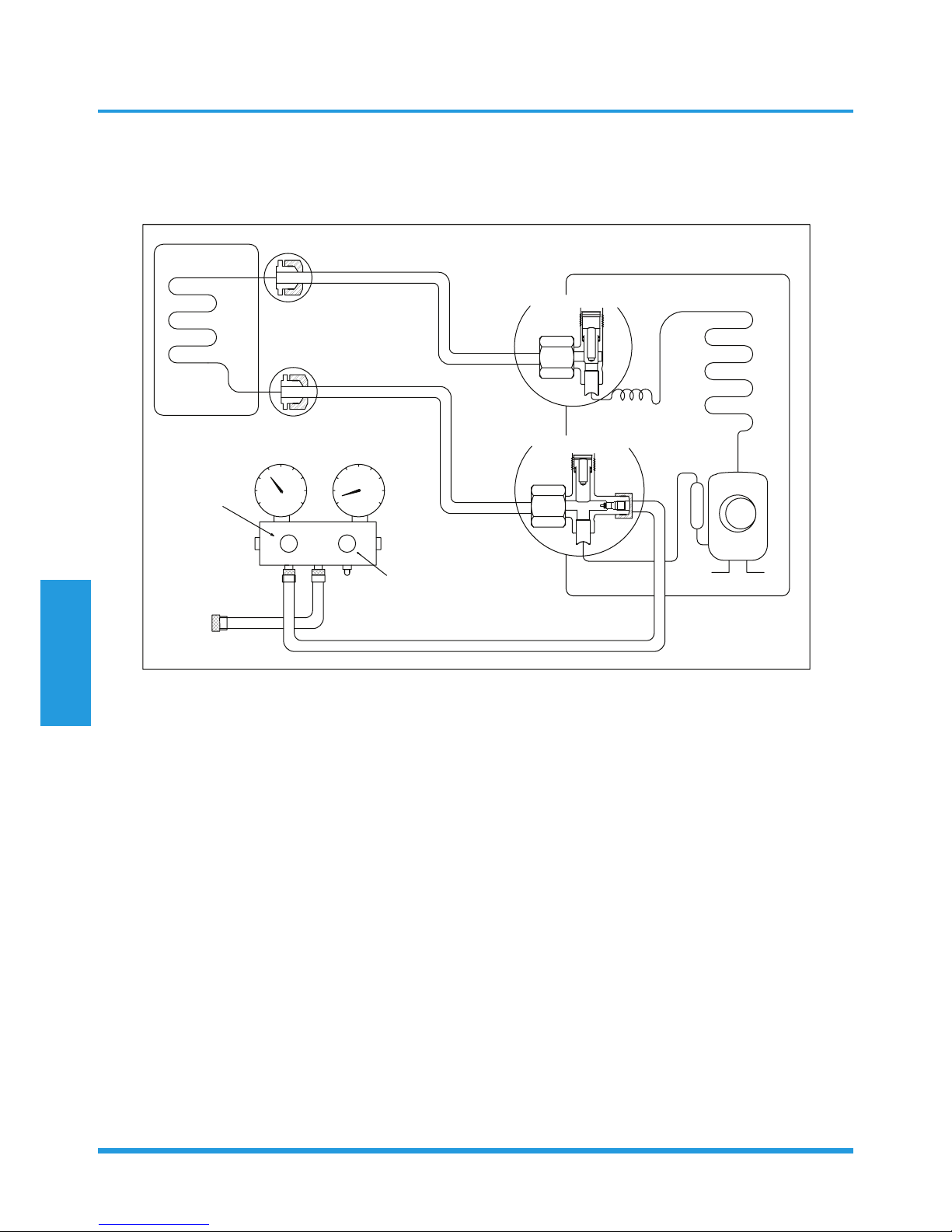
Collecting the refrigerant into the outdoor unit
/TJUUX[TOZ
2OW[OJYOJK
-GYYOJK
)RUYK
)RUYK
:]U]G_\GR\K
:NXKK]G_\GR\K
5[ZJUUX[TOZ
5VKT
)RUYK
2U
.O
Procedure:
1. Confirm that the 2- and 3-way valves are opened.
2. Connect the charge hose with the push pin of Handle
Lo to the 3-way valve’s gas service port.
3. Open the Handle Lo manifold valve to purge air
from the charge hose for 5 seconds and then close it
quickly.
4. Close the 2-way valve.
5. Operate the air conditioner in cooling mode. Cease
operations when the gauge reaches 0.1 MPa
(14.5 Psi).
6. Close the 3-way valve so that the gauge rests
between 0.3 MPa (43.5 Psi) and 0.5 MPa (72.5 Psi).
7. Disconnect the charge set and mount the caps of
service port and 2- and 3-way valves.
8. Use a torque wrench to tighten the caps to a torque
of 18 N.m.
9. Check for gas leakage.
Maintenance and
Disassembly
Page 25
Air purging with vacuum pump
/TJUUX[TOZ
2OW[OJYOJK
-GYYOJK
:]U]G_\GR\K
:NXKK]G_\GR\K
5[ZJUUX[TOZ
)RUYK
)RUYK
3GTOLURJ\GR\K
36G
6XKYY[XK
MG[MK
.GTJRK2U
.GTJRK.O
)NGXMKNUYK
)NGXMKNUYK
<GI[[S
V[SV
<GI[[S
V[SV
)USVU[TJSKZKX
2U
.O
Procedure:
1. Tighten the flare nuts of the indoor and outdoor
units, and confirm that both the 2- and 3-way valves
are closed.
2. Connect the charge hose with the push pin of Handle
Lo to the gas service port of the 3-way valve.
3. Connect another charge hose to the vacuum pump.
4. Fully open the Handle Lo manifold valve.
5. Using the vacuum pump, evacuate the system for 30
minutes.
a. Check whether the compound meter indicates
-0.1 MPa (14.5 Psi).
• If the meter does not indicate -0.1 MPa (14.5
Psi) after 30 minutes, continue evacuating for
an additional 20 minutes.
• If the pressure does not achieve -0.1 MPa (14.5
Psi) after 50 minutes, check for leakage.
• If the pressure successfully reaches -0.1 MPa
(14.5 Psi), fully close the Handle Lo valve, then
cease vacuum pump operations.
b. Wait for 5 minutes then check whether the gauge
needle moves after turning off the vacuum pump.
If the gauge needle moves backward, check
wether there is gas leakage.
6. Loosen the flare nut of the 3-way valve for 6 or 7
seconds and then tighten the flare nut again.
a. Confirm the pressure display in the pressure
indicator is slightly higher than the atmospheric
pressure.
b. Remove the charge hose from the 3-way valve.
7. Fully open the 2- and 3-way valves and tighten the
cap of the 2- and 3-way valves.
 Loading...