


PORTABLE
MODEL:
M2GHP290-12
AIR CONDITIONING SYSTEMS
• USER’S MANUAL
• ΕΓΧΕΙΡΙΔΙΟ ΧΡΗΣΗΣ
• MANUAL UTILIZATORULUI
ENGLISH | ΕΛΛΗΝΙΚΑ | ROMANA

2
EN
Contents
Safety Precautions ................................................................................................................................................3
Cautions ...................................................................................................................................................................4
Warnings (for using R290/R32 refrigerant only) ...........................................................................................5
Preparation .......................................................................................................................................................... 10
Installation ............................................................................................................................................................ 11
Operation ............................................................................................................................................................. 14
Maintenance ....................................................................................................................................................... 17
Troubleshooting ................................................................................................................................................ 18
Design and Compliance Notes ....................................................................................................................... 19
Sociable Remark ................................................................................................................................................. 20

EN
3
|Safety Precautions
WARNING: “Safety Hazard Symbol”, it is very important to please pay close attention to the
below, to avoid any serious injury.
WARNING: To avoid any serious injuries or possible unit damage, please read carefully and
follow the below safety guidelines:
- The installation of this unit must be according to this manual, as improper installation may cause
water leakage, electrical shock or even a re.
- Use only included parts and accessories, and the specied tools for the installation of your
portable air conditioner. The use of parts that are not included in this package may result to water
leakage, electrical shock, re, injury and possible property damage.
- Be certain that the outlet in use, is properly grounded and that of the correct voltage. The threeprong power cord is designed to protect against shock. Information regarding voltage may be
found on the nameplate of your unit.
- This unit must be connected to a properly grounded power supply. If the power supply is not
grounded or protected by a fuse or a circuit breaker (the correct fuse is determined by the
maximum current of the unit, which is located on the nameplate of the device) it is strongly
advised to have a professional qualied electrician install the proper power supply.
- Install on a at and sturdy oor. Failure to install in this manner could result in damage, excessive
noise and even vibration.
- This device should be placed clear of any obstructions to ensure its correct and proper function
and to avoid any possible hazards.
- DO NOT use an extension cord or modify the length of the cord in any way, to power the unit.
- DO NOT combine a single power outlet with other electrical appliances. Irregular power supply
may cause electric shock and a possible re.
- DO NOT install this unit in a very humid room such as a bathroom facility or a laundry room.
Excessive exposure to water may cause the internal electrical components to short circuit.
- DO NOT install in a location exposed to a combustible gas, as this could result to a re.
- The device is equipped with casters for easy mobility. It is suggested not to be used on thick
carpets, as this may cause its tripping.
- DO NOT operate this unit if it has been dropped or damaged in any way.
- For models with heating capabilities, there should be at least 1 meter clear space from any
combustible materials.
- Do not touch this unit with wet or damp hands or while barefoot.
- If the portable air conditioner is knocked over while operating, turn o and unplug from the power
socket immediately. Examine the device ensuring there is no visible damage. If you suspect that
the unit has been damaged, it is necessary to contact a technician or customer support for further
assistance.
- In the event of a thunderstorm, it is suggested to turn o the unit as there is the possibility of
damage due to unsteady power supply.
- Your portable air conditioner should be operated in such a manner, so as to be protected from
moisture. Do not position the unit in an area where possible tripping into water may occur. In this
event, unplug immediately.
- All wiring must be performed strictly in accordance to the wiring diagram which is located
internally.
- The circuit board of the unit (PCB) is designed with an overcurrent protection fuse. Specications
of the fuse are printed on the circuit board, in this manner: T3.15A/250V.

4
EN
|Cautions
CAUTIONS
- This appliance can be used by children aged from 8 years and above and persons with reduced
physical, sensory or mental capabilities or lack of experience and knowledge if they have been
given supervision or instruction concerning use of the appliance in a safe way and understand the
hazards involved. Children shall not play with the appliance. Cleaning and user maintenance shall
not be made by children without supervision.
- This appliance is not intended for use by persons (including children) with reduced physical,
sensory or mental capabilities or lack of experience and knowledge, unless supervised, or
given instruction concerning the use of the appliance by a person responsible for their safety.
(Applicable for non- European countries).
- Minors should be supervised to ensure that there is no mishandling od the device. It is strongly
advised that minors should be supervised when around this unit at all times. If the supply cord
is damaged, it must be replaced by the manufacturer or its service agent or a similarly qualied
person in order to avoid possible hazard.
- Prior to cleaning or maintaining the air conditioner, please make sure the unit is initially turned o
and disconnected from the mains.
- Do not remove any xed covers. If you suspect the unit is not operating properly or if it has been
dropped or damaged in any way it should never be used.
- Do not place the power cord under any carpets, rugs, runners or similar coverings, under
furniture or other appliances. The power cord should be placed in such a manner that accidental
tripping may be avoided.
- If the supply cord is damaged, it must be replaced by the manufacturer or its service agent or a
similarly qualied person in order to avoid a hazard.
- To reduce the risk of possible re or electric shock, do not combine the use of your device with any
Solid- State speed control device (dimmer).
- This unit must be installed in accordance to the national wiring regulations.
- For the proper maintenance of this unit, please contact an authorized technician.
- If any installation is required, please contact an authorized professional installer.
- The inlet or outlet grilles should never be obstructed.
- This unit should be operated only, as per the instructions of this manual, and not for any other
use.
- Prior to cleaning, power o the unit and unplug.
- In the case of any abnormal behavior (e.g.. a burning smell), disconnect power intermediately and
contact your local dealer.
- Do not operate the buttons of the digital control panel with anything other that your hands.
- Do not turn ON/OFF this device by plugging or unplugging the power cord.
- This unit should never be cleaned with the use of hazardous chemicals. The unit should never be
operated in the presence of inammable substances such as pure alcohol, petrol etc.
- Always relocate your portable air conditioner in a vertical position and should always be placed in
a vertical position.
- If the supply cord is damaged, the manufacturer, its service agent or similarly qualied persons
must replace it, in order to avoid a hazard.
- Grip the power plug properly when pulling out of the power socket.
- When inoperative for a long period of time please power o and unplug.

EN
5
|Warnings (for using R290/R32 refrigerant only)
- Do not use any other means other than the recommended to expedite the defrosting process or
to perform a cleaning of the unit, other than those recommended by the manufacturer.
- This device should never be stored in an area in combination with other ignition sources (for
example: a gas appliance an electrical heater, open ames etc.)
- Do not attempt to penetrate the unit with a tool or try to burn.
- Be extra cautious as refrigerant gas may be odorless.
- Appliance 12000 Btu/h should be installed, operated and stored in a room with a oor area larger
than 11m
2
.
Appliance 10000 Btu/h, 9000 Btu/h should be installed, operated and stored in a room with a oor
area larger than 10m
2
.
Appliance 12000 Btu/h,10000 Btu/h should be installed, operated and stored in a room with a
oor area larger than 12m
2
.
- It is necessary to always comply with national gas regulations.
- Keep air ventilation clear of any obstructions.
- The unit should be placed in storage in such a manner as to prevent any mechanical damage from
occurring.
- Always operate this unit in a well- ventilated area, where the room size corresponds to the
specications of the device for optimal performance.
- Any persons involved with the operation and handling of the refrigerant circuit of this unit,
should be certied by the related accredited industry, and authorized as competent to handle
refrigerants, safely, and in accordance to the safety standards of the industry.
- Servicing should be performed only by a certied technician as per the Mnaufacturers
reccomendations. Any maintenance or repair required, should be performed by skilled personnel
who are competent in the use of ammable refrigerants.
Caution: Risk of re/ ammable materials
(Required for R32/R290 units only)
IMPORTANT NOTE: Please read this manual
carefully prior to installing and operating your
device! It is recommended to keep this manual
for future reference.
Description of displayed Symbols (*Only applicable to units with R32/R290 Refrigerant)
WARNING This symbol indicates the use of a ammable refrigerant. If any leakage
occurs, or if exposed to an external ignition source, a re risk is possible.
CAUTION This symbol indicates that the user’s manual should be read carefully.
CAUTION This symbol indicates that a professional service technician should handle
this unit with reference to the user’s manual.
CAUTION This symbol indicates the presence of a user’s or installation manual.

6
EN
1. Transport of equipment containing
ammable refrigerants See transport
regulations
2. Marking of equipment using signs See local
regulations
3. Disposal of equipment using ammable
refrigerants See national regulations.
4. Storage of equipment/appliances
The storage of equipment should be in
accordance as per the user’s manual.
5. Storage of packed (unsold) equipment
The storage of the package should be
constructed in such a manner that if any
mechanical damage to the equipment will not
result ina leak of the refrigerant.
6. Information on Servicing
1) Checking the area
Upon initial work, regarding systems containing
ammable refrigerants, mandatory safety
checks are required to ensure that the risk
of possible ignition is minimized. Prior to
any repairing to the refrigerant system, the
following
2) Work procedure
Any handling should be performed under a
controlled procedure as to minimize the risk
of ammable gas being present while work is
being performed.
3) General work area
All relative maintenance sta and all others
working in the area, should be clearly
instructed, on the nature of the procedure.
Any maintenance in conned spaces must
be avoided. The space around the work- area
should be securely sectioned o. Conrm that
the conditions within the area, are safe and the
ammable material is controlled.
4) Prior to and during work operation, the
area should be checked and monitored by an
appropriate refrigerant detector, also ensuring
the technicians to be aware of potentially
ammable materials in the atmosphere. It is
very important that the refrigerant detector
being used is suitable for the usage with
ammable refrigerants.
5) Presence of re extinguisher
If any work that involves heat, is to be
conducted, the appropriate re extinguishing
equipment should be always available. A dry
powder or CO2 re extinguisher should be
available adjacent to the charging area.
6) No ignition sources
Work that is in relation to a refrigeration
system which involves exposing any pipe works
that contains or has contained ammable
refrigerant gases should be carried out be
no persons, as they may lead to the risk of a
re.All possible re hazards such as cigarette
smoking, must be kept far away from the site
of repair,installation removing and or disposal,
where the possibility of refrigerant gas may
be released to the atmosphere. Prior to the
performance of any work conducted, the area
around the equipment should be monitored
and checked to be certain that no ammable
hazards or ignition risks are present. NO
SMOKING signs are mandatory and must be
displayed..
7) Ventilated area
Prior to any work performed, be certain that
the area is well ventilated or open. Constant
ventilation while any work is carried out is
necessary. Ventilation should safely disperse
any possible refrigerant leak externally into the
atmosphere.
8) Checks to the refrigeration equipment
Where electrical components are being
changed, they should be t for purpose and
with the correct specications. Manufacturer’s
maintenance and Service Guidelines should
be followed at all times. If there is any doubt,
please consult with the manufacturer’s
Technical Debt for assistance. The following
checks should always be performed in regard
to installations using ammable refrigerants:
The charge size is in accordance with the room
size, in which the refrigerant parts are installed.
Be certain the ventilation is operative and check
the outlets do not have any obstructions.
If there is a use of an indirect refrigerant
circuit, this secondary circuit should be
checked for any refrigerant being present. Any
markings to the equipment should be clear
and visible. Markings and signs that are not
clear should be corrected. Any refrigeration
pipe or components should be installed in
such a manner as to never be exposed to any
substance that may lead to the corrosion of
the refrigerant containing components, unless
these components are designed as resistant to
possible corrosion, or are corroded resistant.
9) Checks to electrical devices
|Warnings (for using R290/R32 refrigerant only)

EN
7
|Warnings (for using R290/R32 refrigerant only)
The repair and the maintenance to the electrical
components must include safety checks and
also component inspection procedures. If there
is any fault, that may compromise the safety of
the work applied, then no electrical supply shall
be connected to the circuit until it is corrected. If
the fault cannot be corrected immediately but it
is necessary to continue operation, a temporary
solution may be applied, such as the reporting
to the owner of the equipment, so all parties are
informed.
Initial safety checks shall include:
Capacitors are discharged, in a safe manner to
avoid any possible sparking. No active electrical
components and wirings are exposed while
charging, recovering or purging the system. That
there is continuity of earth bonding.
7. Repairs to sealed components
1) During any performed repairs to sealed
components, all electrical supplies must be
disconnected from the equipment prior to this
act. If it is necessary to have an electrical supply
to the equipment during its servicing, then a
leak detector should be applied as to warn if
there are any signs of potential hazards present.
2) There should be particular attention to
the following as to ensure, that by working on
electrical components there is no alteration
to the casing in such a way that the level of
protection is aected. This includes damage to
the cables, excessive number of connections,
terminals not designed to original specications,
any damage to seals, the incorrect tting of
glands, etc.
Ensure the unit is mounted securely.
Ensure that the seals or any sealing materials
have not degraded in such a manner as
to no longer serve its purpose, preventing
ammable gases entering the atmosphere. Any
replacement parts should be in accordance as
per the manufacturer’s specications.
NOTE: The use of silicon sealant may aect
the eciency of some types of leak detection
equipment. Safe components do not have to be
isolated prior to working.
8. Repair to intrinsically safe components
Do not apply any permanent inductive or
capacitance loads to the circuit without
ensuring that this will not exceed the
permissible voltage and current, allowed for the
equipment in use. Intrinsically safe components
are the only type that can be worked on, while
live in the presence of ammable atmosphere.
The test apparatus should be at the correct
rating. Any replacement of parts should be as
specied by the Manufacturer, as other parts
may result in an ignition of refrigerant gas from
a possible leak.
9.Cabling
Please check that cables are not subject to wear,
corrosion, excessive pressure, vibration, or any
other adverse environmental eects. Aging or
continual vibration, should also be taken into
account.
10. Detection of ammable refrigerants
Under no circumstance may a potential ignition
source, such as a halide torch or any detector
with the use of a ame, may be used.
11. Leak detection methods
The following leak detection methods are
acceptable for systems containing ammable
refrigerants.
Electronic leak detectors may be used to detect
ammable refrigerants. However, the sensitivity
may not be adequate, or it is possible it may
need re- calibration.
(Detection equipment should be calibrated in
a refrigerant- free area) It should be ensured
that the detector is not a possible ignition
source and is suitable for the refrigerant used.
Leak detection equipment should be set at a
percentage of the LFL of the refrigerant used.
Leak detection equipment should be set at
a percentage of the LFL of the refrigerant
and should be calibrated to the refrigerant
employed and the appropriate percentage
of gas (25% maximum) is conrmed. Leak
detection uids are suitable for use with
most refrigerants but the use of detergents
containing chlorine must be avoided as the
chlorine may react with the refrigerant and
corrode the copper pipe- work. If a leak is
suspected, all ames must be extinguished. If a
leakage of refrigerant is spotted which requires
brazing, all of the refrigerant shall be recovered
from the system, or isolated (by means of
shutting o the valves) in a part of the system
away from the leak. Oxygen free nitrogen (OFN)
should then be purged through the system
both before and during the brazing process.
12. Removal and evacuation
When interfering with the refrigerant circuit

8
EN
in order to make any repairs or for any other
purposes, conventional procedures should
be applied. However, it is strongly suggested
that safe practice is followed, and ammability
should be taken under consideration.
The following procedure should be followed as
to:
Remove refrigerant,
Purge the circuit with inert gas,
Evacuate,
Purge again with inert gas,
Open the circuit by performing a cut or brazing.
The refrigerant charge should be recovered
into the assigned and correct recovery
cylinders, The system must be ushed with OFN
to render the unit safe, This process may be
repeated several times. The use of Compressed
air oxygen may not be used for this act.
Flushing may be achieved by breaking the
vacuum in the system with OFN and continuing
to ll until the working pressure has been
achieved, then venting to atmosphere, and
nally pulling down to a vacuum. This process
should be repeated until no refrigerant is left
within the system. When the nal OFN charge
is used, the system shall be vented down to
atmospheric pressure to enable any work to be
performed. This operation is absolutely crucial
if brazing operations on the pipe- work are
intended to take place.
Ensure that the outlet for the vacuum pump is
not close to any ignition sources and there is
plenty of ventilation available.
13. Charging procedures
In addition to conventional charging
procedures, the following requirements should
be followed.
Ensure that the contamination of dierent
refrigerants does not occur when using
charging equipment. Hoses or lines shall be as
short as possible to minimise t he amount of
refrigerant contained in them.
Cylinders shall be kept in an upright position.
Ensure that the refrigeration system is
earthed prior to charging the system with any
refrigerant.
Label the system when charging is complete (if
not labeled already).
Extreme care mustl be taken not to overll
the refrigeration system. Prior to recharging
the system, it must be pressure tested with
OFN. The system must also be leak tested
on completion of charging but prior to
commissioning. A follow up leak test should be
carried out prior to leaving the site.
14. Decommissioning
Before carrying out this procedure, it is
essential that the technician is completely
familiar with the equipment and all its details.
It is considered as good practice that all
refrigerants are recovered safely. Prior to the
task being carried out, an oil and refrigerant
sample shall be taken, in the event that analysis
is required prior to re- use of reclaimed
refrigerant. It is essential that electrical power is
available before the task is commenced.
a) Become familiar with the equipment and its
operation.
b) Electrically isolate the system.
c) Before attempting this procedure please
ensure that: Mechanical handling equipment
is available, if required, for handling refrigerant
cylinders;
All personal protective equipment is available
and being used correctly; The recovery process
is supervised at all times by a competent
person;
Recovery equipment and cylinders conform to
the appropriate standards.
d) Pump down refrigerant system, if possible.
e) If a vacuum is not possible, make a manifold
so that refrigerant can be removed from
various parts of the system.
f) Make sure that cylinder is situated on the
scales before recovery takes place.
g) Start the recovery machine and operate in
accordance with manufacturer's instructions.
h) Do not overll cylinders. (No more than 80 %
volume liquid charge).
i) Do not exceed the maximum working
pressure of the cylinder, even temporarily.
j) When the cylinders have been lled correctly
and the process completed, make sure that the
cylinders and the equipment are removed from
site promptly and all isolation valves on the
equipment are closed o.
k) Recovered refrigerant shall not be charged
into another refrigeration system unless it has
been cleaned and checked.
15. Labelling
Equipment must be labelled stating that it
has been de- commissioned and emptied of
|Warnings (for using R290/R32 refrigerant only)

EN
9
refrigerant. The label must be dated and signed.
Ensure that there are labels on the equipment
stating the equipment contains ammable
refrigerant.
16. Recovery
When removing refrigerant from a system,
either for servicing or decommissioning,
it is recommended good practice that all
refrigerants are removed in a safe manner.
When transferring refrigerant into cylinders,
ensure that only appropriate refrigerant
recovery cylinders are employed.
Ensure that the correct number of cylinders
for holding the total system charge is available.
All cylinders to be used are designated for
the recovered refrigerant and labelled for
that refrigerant (i.e. special cylinders for
the recovery of refrigerant). Cylinders shall
be complete with pressure relief valve and
associated shut- o valves in good working
order. Empty recovery cylinders are evacuated
and, if possible, cooled before recovery
occurs.
The recovery equipment shall be in good
working order with a set of instructions
concerning the equipment that is at hand and
shall be suitable for the recovery of ammable
refrigerants. In addition, a set of calibrated
weighing scales shall be available and in good
working order. Hoses shall be complete with
leak- free disconnect couplings and in good
condition. Before using the recovery machine,
check that it is in satisfactory working order,
has been properly maintained and that any
associated electrical components are sealed
to prevent ignition in the event of a refrigerant
release. Consult manufacturer if in doubt.
The recovered refrigerant shall be returned to
the refrigerant supplier in the correct recovery
cylinder, and the relevant Waste Transfer
Note arranged. Do not mix refrigerants in
recovery units and especially not in cylinders.
If compressors or compressor oils are to
be removed, ensure that they have been
evacuated to an acceptable level to make
certain that ammable refrigerant does not
remain within the lubricant. The evacuation
process shall be carried out prior to returning
the compressor to the suppliers. Only electric
heating to the compressor body shall be
employed to accelerate this process. When oil
is drained from a system, it shall be carried out
safely.
Important Note Regarding Fluorinated
Gasses
- Fluorinated greenhouse gases are contained
in rmly sealed equipment. For specic
information on the type, the amount and the
CO
2
equivalent in tonnes of the uorinated
greenhouse gas (on some models), please refer
to the relevant label on the unit itself.
- Installation, service, maintenance and repair of
this unit must be performed only by a certied
technician.
- Unit un- installation and the recycling of, must
be performed by a certied technician.
|Warnings (for using R290/R32 refrigerant only)

10
EN
|Preparation
rear
MODEL A
MODEL B
power plug socket
power cord buckle
bottom tray
drain outlet
power cord outlet
drain outlet
(only for pump
heating mode)
upper air filter
(behind the grille)
upper air intake
air outlet
lower air filter
lower air intake
drain outlet
front
rear
control panel
handle
(both sides)
horizontal louver
blade
(swing automatically)
Caster
power plug socket
power cord buckle
vent control
bottom tray
drain outlet
power cord outlet
drain outlet
(only for pump
heating mode)
upper air filter
(behind the grille)
upper air intake
air outlet
lower air filter
lower air intake
drain outlet
Panel
SCALE 0.500

EN
11
|Installation|Installation
Choosing The Right Location
Tools Needed
Medium Philips screwdriver; - Tape measure or ruler; - Knife or scissors; - Saw (optional, to shorten
window adaptor for narrow windows).
Accessories
Check your window size and choose the t window slider.
50cm
19.7inch
Recommend Installation
NOTE: Items with * are optional. Slight variations in design may occur.
- The air conditioner should be placed on a rm foundation to
minimize noise and vibration. For safe and secure positioning,
place the unit on a smooth, level oor strong enough to
support the unit.
- The unit must be placed near a properly rated grounded
outlet.
- Allow at least 30cm of space from the wall for ecient air-
conditioning.
- Never obstruct the air inlet or outlet of the unit.
NOTE:
All the illustrations in this manual are for explanatory purposes
only. Your air conditioner may be slightly dierent. The actual
shape and size may vary.
The unit can be controlled by the unit control panel alone
or with the remote controller. This manual does not include
Remote Controller Operations, see the "Remote Controll
Illustration" packed with the unit for details.
There is the possibility of dierences between the user’s
manual and the illustrated photos of the remote control,
always refer to the manual for information.

12
EN
Europe
Part Description Quantity
Unit Adaptor
1 pc
Exhaust Hose
1 pc
*
Window Slider Adaptor
1 pc
*
Wall Exhaust Adaptor A
(only for wall installation)
1 pc
*
Wall Exhaust Adaptor B
(with cap) (only for wall
installation)
1 pc
*
Screw and anchor
(only for wall installation)
4 set
*
Window Slider A
1 pc
*
Window Slider B
1 pc
Power Cord Buckle
1 pc
Part Description Quantity
*
Bolt
1 pc
*
Security Bracket and Screw
1 set
Drain Hose
1 pc
Drain Hose Adaptor(only for
heat pump mode)
1 pc
*
Foam Seal A (Non- adhesive)
2 pc
*
Foam Seal B (Adhesive)
2 pc
*
Foam Seal C (Adhesive)
1 pc
ON/OFF
TEMP
SHORT
CUT
TIMER
ON
TIMER
OFF
MODE
FAN
SLEEP
SWING
LED
Remote Controller
and Battery
1set
NOTE: Items with * are optional. Slight variations in design may occur.
|Installation
Unit adaptor
Window slider
adaptor
Exhaust hose
Press into Press into
Exhaust hose
assembly
or
Make sure the hook of the adaptor is aligned
with the hole seat of the air outlet.
Hook
Hole Seat
Lower groove
adaptor
Make sure the adaptor is
inserted into the lower
groove of the air outlet.
Window slider A
MODEL A
MODEL A
MODEL B
MODEL B
Window slider B
Bolt
Window slider A Window slider B
Bolt
or
or
Window slider A Window slider B
Window slider C
Bolts
Window slider A Window slider B
Window slider C
Bolts
Window Installation Kit
Step One: Preparation of the Exhaust Pipe
Apply pressure to the exhaust pipe and the window
adaptor one side, and the unit adaptor on the other, attach
with the use of the elastic buckles located on the adaptors.
Step Two: Install the Exhaust hose assembly to the unit
Insert unit adaptor of the Exhaust hose assembly into
the lower groove of the air outlet of the unit while the
hook of the adaptor is aligned with the hole seat of the
air outlet and slide down the Exhaust hose assembly
along the arrow direction for installation.
Step Three: Preparing the Adjustable Window Slider
1. Depending on the window size, make necessary
adjustments on the window slider.
2. If the length of the window requires two window
sliders, use the bolt to fasten the window sliders once
they are adjusted to the proper length.
3. For some models, if the length of the window
requires three window sliders(optional), use two bolts
to fasten the window sliders once they are adjusted to
proper length.

EN
13
2 Screws
Security Bracket
Foam seal B
(Adhesive type-shorter)
Foam seal A
(Adhesive type)
Window slider A
Window slider B
(if required)
Foam seal C
(Non-adhesive type)
Foam seal C
(Non-adhesive type)
2 Screws
Security
Bracket
or
or
or
or
or
or
MODEL A
MODEL B
Foam seal B
(Adhesive type-shorter)
Foam seal A
(Adhesive type)
Window slider A
Window slider B
(if required)
VENT CONTROL feature
CL OS E
OP EN
max 120cm or 47 inch
min 30cm or 12 inch
Expansion anchor
position
Adaptor cap
Wall Exhaust
Adaptor B
|Installation|Installation
Note: Once the Exhaust Hose assembly and
Adjustable Window Slider are prepared, choose
from one of the following installation methods.
Type 1: Hung Window or Sliding Window
Installation (optional)
Type 2: Wall Installation (optional)
1.Cut a 125mm (4.9inch) hole into the wall
for the Wall Exhaust Adaptor B. 2.Secure the
Wall Exhaust Adaptor B to the wall using the
four Anchors and Screws provided in the kit.
3.Connect the Exhaust Hose Assembly (with
Wall Exhaust Adaptor A) to the Wall Exhaust
Adaptor B.
1. Cut the foam seal (adhesive type) to the
proper length and attach it to the window
frame.
2. Attach the window slider kit to the window
opening.
4.If desired, install the security bracket with 2
screws as shown.
5.Insert the window slider adaptor into the hole
of the window slider.
3.Cut the non- adhesive foam seal C strip to match
the width of the window. Insert the seal between
the glass and the window frame to prevent air and
insects from getting into the room.
Note: Cover the hole
using the adaptor cap
when not in use.
Note: To ensure proper function, DO NOT
overextend or bend the hose. Make sure that
there is no obstacle around the air outlet of the
exhaust hose (in the range of 500mm) in order
to the exhaust system works properly. All the
illustrations in this manual are for explanation
purpose only.
Your air conditioner may be slightly dierent.
The actual shape shall prevail.
The Vent Control is located at the back of the
air conditioner. The OPEN position removes
stale air from the room and exhausts it to the
outside. Fresh air is drawn in through normal
passages in the home.
When not need to circulate the room air, set
Vent Control to CLOSE position. This function is
only applicable for MODEL B.

14
EN
HEAT mode light
HIGH fan speed light
MED fan speed light
LOW fan speed light
AUTO fan speed light
ION light
SLEEP light
Degrees Celsius
Degrees Fahrenheit
LED display
FOLLOW ME light
FILTER light
POWER MANAGEMENT light
COOL mode light
FAN mode light
DRY mode light
AUTO mode light
WIRELESS light
|Operation
NOTE: On some models is instead of °F. On some models (WIRELESS light) is instead of
(power light).
NOTE: ION, FOLLOW ME, WIRELESS features are not available. ION is not applicable
for R32/R290 units.
NOTE: The control panel may be look like the following:

EN
15
|Operation
Swing button
Used to initiate the Auto swing feature. When
the operation is ON, press the SWING button
can stop the louver at the desired angle.
Timer button
Used to initiate the AUTO ON start time and
AUTO OFF stop time program, in conjuction
with the + & - buttons. The timer on/o
indicator light illuminates under the timer
on/o settings.
Mode button
Choose the desired operating mode. By
pressing the MODE button each time an
operation is selected in the following order:
AUTO, COOL, DRY, FAN and HEAT (cooling
only models without). Indication led will
illuminate under the desired MODE setting.
Up (+) and Down (- ) buttons
Used to adjust (increasing/decreasing)
temperature settings in 1°C/1°F (or 2 °F)
increments in a range of 17°C/62°F to
30°C/86°F (or 88°F) or the TIMER setting in a
range of 0~24hrs.
NOTE: The remote control may display the
temperature in both Fahrenheit or Celsius.
To change press and hold the up/down
buttons for 3 sec.
Fan
Control the fan speed. Press to select the
fan speed in four steps- LOW, MED, HIGH
and AUTO. The fan speed indicator light
illuminates under dierent fan settings.
When select AUTO fan speed, all the fan
indicator lights turn dark. On some models,
when select AUTO fan speed, all the fan
indicator lights illumiante(optional).
Sleep(Eco) button
Used to initiate the SLEEP/ECO operation.
Power button
Power switch on/o.
LED display
Shows the set temperature in °C or °F
("°F" no display for some models) and the
Auto- timer settings. While on DRY and FAN
modes, it shows the room temperature.
Shows Error codes and protection code:
E1- Room temperature sensor error.
E2- Evaporator temperature sensor error.
E3- Condenser temperature sensor error
(on some models).
E4- Display panel communication error.
EC- Refrigerant leakage detection
malfunction (on some models).
P1- Bottom tray is full- Connect the drain
hose and drain the collected water away.If
protection repeats,call for service.
Note: When one of the above malfunctions
occurs, turn o the unit, and check for
any obstructions. Restart the unit, if the
malfunction is still present, turn o the
unit and unplug the power cord. Contact
the manufacturer or its service agents or a
similar qualied person for service.
Exhaust hose installation
The exhaust hose and its adaptor should
be installed or removed according to the
usage mode. Under COOL,HEAT(heat pump
type) or AUTO mode the exhaust hose must
be installed, under FAN,DEHUMIDIIFY or
HEAT(electrical heat type) the exhaust hose
should be removed.

16
EN
SCALE 0.500
SCALE 0.500
SCALE 0.500
X
drain hose
adaptor
Press the power
cord buckle into
the rear cover.
drain hose
adaptor
√
delivery lift <1.8m
Operation Instructions
COOL operation
- Press the "MODE" button until the "COOL" indicator
light comes on.
- Press the ADJUST buttons "+" or "- " to select your
desired room temperature. The temperature can be set
within a range of 17°C~30°C/62°F~86°F(or 88°F).
- Press the "FAN SPEED" button to choose the fan
speed.
HEAT operation(cooling only models without)
- Press the "MODE" button until the "HEAT" indicator
light comes on.
- Press the ADJUST buttons "+" or " - " to select your
desired room temperature. The temperature can be set
within a range of 17°C~30°C/62°F~86°F(or 88°F).
- Press the "FAN SPEED" button to choose the fan
speed. For some models, the fan speed can not be
adjusted under HEAT mode.
DRY operation
- Press the "MODE" button until the "DRY" indicator light
comes on.
- Under this mode, you cannot select a fan speed or
adjust the temperature. The fan motor operates at LOW
speed.
- Keep windows and doors closed for the best
dehumidifying eect.
- Do not put the duct to window.
AUTO operation
- When you set the air conditioner in AUTO mode, it
will automatically select cooling, heating(cooling only
models without), or fan only operation depending on
what temperature you have selected and the room
temperature.
- The air conditioner will control room temperature
automatically round the temperature point set by you.
- Under AUTO mode, you can not select the fan speed.
NOTE: Under AUTO mode, both the AUTO mode and
the actual operation mode indicator lights illuminate for
some models.
FAN operation
- Press the "MODE" button until the"FAN " indicator light
comes on.
- Press the "FAN SPEED" button to choose the fan
speed. The temperature can not be adjusted.
- Do not put the duct to window.
TIMER operation
- When the unit is on, press the Timer button will initiate
the Auto- o stop program, the TIMER OFF indicator
light illuminates. Press the UP or down button to select
the desired time. Press the TIMER button again within 5
seconds, the Auto- on start program is initiated.
And the TIMER ON indicator light illuminates. Press the
up or down button to select the desired Auto- on start
time.
When the unit is o, press the Timer button to initiate
the Auto- on start program, press it again within 5
seconds will initiate the Auto- o stop program.
- Press or hold the UP or DOWN button to change the
Auto time by 0.5 hour increments, up to 10 hours, then
at 1 hour increments up to 24 hours. The control will
count down the time remaining until start.
- The system will automatically revert back to display the
previous temperature setting if there is no operation in
a 5 seconds period.
- Turning the unit ON or OFF at any time or adjusting the
timer setting to 0.0 will cancel the Auto Start/Stop timer
program.
SLEEP (ECO) operation
- Press this button, the selected temperature will
increase (cooling) or decrease(heating) by 1°C/2°F(or
1°F) 30 minutes. The temperature will then increase
(cooling) or decrease (heating) by another 1°C/2°F(or
1°F) after an additional 30 minutes. This new
temperature will be maintained for the next 7 hours,
after the duration of the above time frame the unit will
return to the initial set temperature and ending the
SLEEP mode. NOTE: This feature is not available under
DRY or FAN mode.
Other features
AUTO- RESTART
In the event of power loss the unit will regain operation,
once power resumes, with the last settings.
AIR FLOW DIRECTION ADJUSTMENT
The louver can be adjusted automatically. Adjust the air
ow direction automatically:
- When the Power is ON, the louver opens fully.
- Press the SWING button on the panel or remote
controller to initiate the Auto swing feature. The louver
willl swing up and down automatically.
- Please do not adjust the louver manually.
|Operation

17
SCALE 0.500
SCALE 0.500
SCALE 0.500
X
drain hose
adaptor
Press the power
cord buckle into
the rear cover.
drain hose
adaptor
√
delivery lift <1.8m
WAIT 3 MINUTES BEFORE RESUMING OPERATION
Once the unit has stopped its operation, it can not be
restarted within the rst 3 minutes, for the protection
of the device. Operation will automatically restart after
3 minutes.
POWER MANAGEMENT feature
When the ambient temperature is lower than the
setting temperature for a period of time, the unit
will be automatically operate power management
feature. The compressor and fan motor stop. When
the ambient temperature is higher than the setting
temperature, the unit will be automatically quit the
power management feature. The compressor and (or)
fan motor run.
NOTE: For unit with power management light, the
light will illuminate under this feature.
Water drainage
- When under dehumidifying mode, remove the
drain plug for the back of the unit and install the drain
connector (5/8 universal female mender) with a 3/4
hose (may be purchased locally). For models without
the drain connector, please attach the drain hose to
the outlet, while placing the other side of the hose
directly over the drainage port of your basement oor.
During heating pump mode, remove the lower
drain plug from the back of the unit, install the drain
connector(5/8" universal female mender) with 3/4"
hose(locally purchased). For the models without drain
connector, just attach the drain hose to the hole. Place
the open end of the Hose adaptor directly over the
drain area in your basement oor.
NOTE: Βe certain the hose is secure without any
leaking. Direct the hose toward the drain, in such a
manner that there are no breaks or bents securing
smooth water ow. (See Figs with R. Do never let it up.
(See Figs with S ). When the continuous drain hose is
not of use, ensure the drain plug is installed rmly to
prevent possible leakage.
- When the water level of the bottom tray reaches a
predetermined level, the unit beeps 8 times; the digital
display area shows “PI”. At this time
the air conditioning/dehumidication
process will immediately stop.
However, the fan motor will continue to
operate (this is normal). Carefully move
the unit to a drain location, remove the
bottom drain plug and let the water
drain . Re- install the bottom drain plug and restart the
machine until the “PI” symbol disappears. If the error
persists, please call for service.
NOTE: Be sure to reinstall the bottom drain plug
rmly to prevent leakage before using the unit.
| Maintenance
WARNING:
- Be sure to unplug the unit before cleaning or
servicing
- DO NOT use ammable liquids or chemicals to
clean the unit.
- Do not wash the unit directly under a tap or
using a hose as it may cause electrical shock.
- DO NOT operate this unit if the power cable
is damaged in any way. If the power cord is
damaged it must be replaced from the product
manufacturer and never repaired.
Clean the Air Filter
CAUTION
DO NOT operate the unit without lter because
dirt and lint will clog it and reduce performance.
|Operation
SCALE 0.500
SCALE 0.500
Remove the air filter
Upper filter
(take out)
Remove the
screw,then
take the lower
filter out.
MODEL A
MODEL B
MODEL A
MODEL B
MODEL A
MODEL B
√
drain hose
adaptor
Continuous
drain hose
Remove the
lower drain plug
√
drain hose
adaptor
Continuous
drain hose
Remove the
lower drain plug
SCALE 0.500
Remove the
upper drain plug
√
Continuous
drain hose
Remove the
upper drain plug
√
Continuous
drain hose
Uper air filter
(take out)
Lower air filter
(take out)
SCALE 0.500
SCALE 0.500
SCALE 0.500
X
drain hose
adaptor
Press the power
cord buckle into
the rear cover.
drain hose
adaptor
√
delivery lift <1.8m
MODEL A
MODEL B
SCALE 0.500
Remove the
upper drain plug
√
Continuous
drain hose
Remove the
upper drain plug
√
Continuous
drain hose
SCALE 0.500
SCALE 0.500
SCALE 0.500
X
drain hose
adaptor
Press the power
cord buckle into
the rear cover.
drain hose
adaptor
√
delivery lift <1.8m
SCALE 0.500
Remove the air filter
Upper filter
(take out)
Remove the
screw,then
take the lower
filter out.
MODEL A
MODEL B
Uper air filter
(take out)
Lower air filter
(take out)
SCALE 0.500
SCALE 0.500
SCALE 0.500
X
drain hose
adaptor
Press the power
cord buckle into
the rear cover.
drain hose
adaptor
√
delivery lift <1.8m

18
EN
|Maintenance
| Troubleshooting
Maintenance Tips
- Clean the air lter every two weeks to prevent
inferior fan operation due to dust.
- The water collection tray must be drained
immediately in the event that the error P1 appears
on the digital control panel, and also before
storage to prevent the possibility of mold growth.
- In households with animals, you will have to
periodically wipe down the grill to prevent blocked
airow due to animal hair.
Clean the Unit
Use a damp lint- free cloth to clean the unit
enclosure. Dry with a clean and lint free cloth cloth.
Store the unit when not in use
- Drain the unit's water collection tray as per the
instructions in the following section.
- Operate the device on FAN mode for 12 hours in
a warm room to dry and prevent the possibility of
mold growth.
- Power o the unit and unplug.
- Clean the air lter as per the instructions in the
previous section. Reinstall the clean and dry lter
before storing.
- Batteries from the remote control should be
removed.
- Store in a cool, shady area. Any exposure directly
to sunlight or in extreme heat situations may
minimize the lifespan of this device.
NOTE: The main chassis and front of the unit
may be cleaned with by using a lint- free cloth and
soapy water (using a mild detergent) Dry with a
clean cloth. The use of harsh cleansers, or the
waxing and polishing of the unit is strongly not
advised. When cleaning the digital control panel
be certain the cloth is dry as any water around the
controls may cause damage to the unit.
Problem Possible Cause Troubleshooting
Unit does not turn on
when pressing ON/OFF
button
P1 Error Code The Water Collection Tray is full.
Turn o the unit, drain the water
from the Water Collection Tray and
restart the unit.
In COOL mode: room
temperature is lower than the
set temperature
Reset the temperature
Unit does not cool well
The air lter is blocked with dust
or debris
Turn o the unit and clean the lter
according to instructions
Exhaust pipe is not connected
or is blocked
Turn o the unit, disconnect the
hose, check for blockage and
reconnect the hose
The unit is low on refrigerant Call a service technician to inspect
the unit and top o refrigerant
Temperature setting is too high Lower the set temperature
The windows and doors in the
room are open
Conrm all windows and exits are
shut
The room area is too large Double- check the cooling area
There are heat sources inside
the room
Remove the heat sources if
possible
The unit is noisy and
vibrates too much
The ground is not level Place the unit on a at, level surface
The air lter is blocked with dust
or debris
Turn o the unit and clean the lter
according to instructions
The unit makes a gurgling
sound
This sound is caused by the ow
of refrigerant inside the unit
This is normal
Please refer to the below prior to contacting customer support.

EN
19
|Design and Compliance Notes
Design Notice:
The design and the specications of this unit are subject to change at any given moment, without
prior notice, for the improvement of the product. Always consult with the after sales department or
the manufacturer for further details. Manuals are also subject to updates and you should always
check for the latest version by visiting the manufacturer’s website.
Energy Rating Information
The energy rating of this unit is based on typical installation with the use of the provided, and not
extended, exhaust pipe, without the use of the window slider adaptor or the wall exhaust adaptor A
(as shown in the Installation section of this manual).
Unit Temperature Range
Mode Temperature Range
Cool 17- 35°C (62- 95°F)
Dry 13- 35°C (55- 95°F)
Heat (pump heat mode) 5- 30°C (41- 86°F)
Heat (electrical heat mode) 30°C (86°F)
NOTE: To be in compliance EN 61000- 3- 11, the product M2GHP290-12 shall be connected only
to a supply of the system impedance: | Zsys|=0.348 ohms or less. Before connect the product
to public power network, please consult your local power supply authority to ensure the power
network meet above requirement.

20
EN
|Sociable Remark
When using this unit in the European countries, the following information must be followed:
DISPOSAL: Do not dispose this product as unsorted municipal waste. This appliance requires
special treatment for disposal.
It is prohibited to dispose of this appliance in domestic household waste.
There are several possibilities for disposal:
A. Your local municipality has established free collection systems for electronic waste.
B. Your local retailer will take back the old product with the purchase of a new product.
C. The manufacture will take back the old appliance for disposal.
D. The old products contain valuable resources and sometimes can be sold to scrap metal dealers.
Do not dispose this product randomly into the environment. The hazardous substances can leak
into the ground- water supply and nd their way into the food chain, endangering your health
and the environment.
All the pictures in the manual are for explanatory purposes only. The actual shape of the unit
you purchased may be slightly dierent, but the operations and functions are the same.
The company may not be held responsible for any misprinted information. The design and the
specications of the product for reasons, such as product improvement, are subject to change
without any prior notice.
Please consult with the manufacturer at +30 211 300 3300 or with the Sales agency for further
details. Any future updates to the manual will be uploaded to the service website, and it is
advised to always check for the latest version.
Scan here to download the latest version of this manual.
www.inventorairconditioner.com/media- library

Activate your Warranty
l Visit our web site and activate your warranty via the below link or by
scanning the QR code
https://www.inventorairconditioner.com/warranty-inventor
l Fill all the elds as shown below
þ
once the warranty submission has been completed a conrmation message will be
sent to your email
Full Name*
Address*
Postal Code*
Phone Number*
E-mail*
Unit Type*
Serial Number of the unit*
Date of Purchase*
Invoice Number*
Additional Details
Subscribe to Inventor's Newsletter
Owner details Unit details
To activate the warranty card, please ll in the following elds
* Required eld
With the current warranty card you accept the terms and conditions.
SEND

22
GR
|Περιεχόμενα
Οδηγίες Ασφαλείας ........................................................................................................................................... 23
Προειδοποιήσεις (αφορά ψυκτικό υγρό τύπου R290/ R32) .................................................................. 25
Εγκατάσταση ....................................................................................................................................................... 31
Λειτουργία ........................................................................................................................................................... 34
Συντήρηση ........................................................................................................................................................... 38
Σφάλματα ............................................................................................................................................................. 39
Σχεδιασμός και Προδιαγραφές ...................................................................................................................... 40
Γενικές Παρατηρήσεις - Απόρριψη Συσκευής ........................................................................................... 41

GR
23
|Οδηγίες Ασφαλείας
Προειδοποίηση: Αυτό το σύμβολο υποδεικνύει ότι μπορεί να προκληθεί θάνατος ή σοβαρός
τραυματισμός σε περίπτωση που δεν ακολουθήσετε τις οδηγίες.
Προειδοποίηση: Για την αποφυγή θανάτου, προσωπικού τραυματισμού ή τραυματισμού
τρίτων πρέπει να ακολουθούνται οι παρακάτω οδηγίες. Αγνοώντας τις οδηγίες, μπορεί να προκληθεί
θάνατος ή ζημιά.
-Η εγκατάσταση πρέπει να εκτελείται σύμφωνα με τις οδηγίες. Λανθασμένη εγκατάσταση μπορεί να
προκαλέσει διαρροή νερού, ηλεκτροπληξία ή πυρκαγιά.
-Χρησιμοποιείτε μόνο τα συμπεριλαμβανόμενα εξαρτήματα, ανταλλακτικά και τα ειδικά εργαλεία για
την εγκατάσταση. Χρησιμοποιώντας μη τυποποιημένα εξαρτήματα μπορεί να προκληθεί διαρροή
νερού, ηλεκτροπληξία, πυρκαγιά, τραυματισμός ή ζημιά.
-Βεβαιωθείτε ότι η πρίζα που χρησιμοποιείτε είναι γειωμένη και διαθέτει την κατάλληλη τάση. Το
καλώδιο τροφοδοσίας είναι εξοπλισμένο με τριών ακροδεκτών βύσμα γείωσης για την προστασία
από ηλεκτροπληξία. Πληροφορίες για την τάση μπορείτε να βρείτε στην ετικέτα τεχνικών
προδιαγραφών που φέρει η μονάδα.
- Η μονάδα σας θα πρέπει να συνδέεται σε μια κατάλληλα γειωμένη πρίζα τοίχου. Εάν η πρίζα που
σκοπεύετε να συνδέσετε την μονάδα δεν είναι επαρκώς γειωμένη ή δεν διαθέτει ασφαλειοδιακόπτη
η διακόπτη κυκλώματος (ο ασφαλειοδιακόπτης και ο διακόπτης κυκλώματος ορίζονται από τη
μέγιστη ένταση ρεύματος που αναφέρεται στην ετικέτα τεχνικών προδιαγραφών που φέρει η
μονάδα), απευθυνθείτε σε εξειδικευμένο ηλεκτρολόγο ώστε να πραγματοποιήσει την ηλεκτρολογική
εγκατάσταση.
-Εγκαταστήστε τη μονάδα σε μια επίπεδη και σταθερή επιφάνεια. Διαφορετικά μπορεί να προκληθεί
πτώση από κραδασμούς, βλάβη ή έντονος θόρυβος.
- Βεβαιωθείτε ότι δεν υπάρχουν εμπόδια περιμετρικά της μονάδας και διασφαλίστε την σωστή
λειτουργία της.
- ΜΗΝ τροποποιείτε το μήκος του καλωδίου ρεύματος και μην χρησιμοποιείτε μπαλαντέζα για την
τροφοδοσία της μονάδας.
- ΜΗΝ συνδέετε την συσκευή σε πολύμπριζο με συνδεδεμένες και άλλες ηλεκτρικές συσκευές.
Ακατάλληλη παροχή ηλεκτρικού ρεύματος μπορεί να προκαλέσει πυρκαγιά ή ηλεκτροπληξία.
- ΜΗΝ εγκαθιστάτε το κλιματιστικό σας σε δωμάτιο με έντονη υγρασία, όπως μπάνιο ή πλυσταριά.
Έντονο ποσοστό υγρασίας στον χώρο μπορεί να προκαλέσει ηλεκτρικές δυσλειτουργίες ή
βραχυκύκλωμα στη συσκευή.
- ΜΗΝ τοποθετείτε τη συσκευή κοντά σε φθοριούχα αέρια, καθώς μπορεί να προκληθεί πυρκαγιά.
- Η μονάδα διαθέτει ρόδες για εύκολη μετακίνηση. Βεβαιωθείτε ότι δεν μετακινείτε την μονάδα πάνω
σε χαλί ή άλλα αντικείμενα, ώστε να αποφύγετε ενδεχόμενη ανατροπή της συσκευής.
- ΜΗΝ θέτετε σε λειτουργία την μονάδα σε περίπτωση που έχει πέσει ή έχει υποστεί κάποια ζημιά.
- Η συσκευή με ηλεκτρικό θερμαντήρα πρέπει να έχει τουλάχιστον 1 μέτρο απόσταση από εύφλεκτα
αέρια.
- ΜΗΝ λειτουργείτε τη συσκευή με βρεγμένα ή υγρά χέρια ή όταν είστε ξυπόλητοι.
- Αν το κλιματιστικό χτυπηθεί κατά την χρήση, απενεργοποιήστε τη μονάδα και αποσυνδέστε την
αμέσως από την παροχή ρεύματος. Ελέγξτε οπτικά για να βεβαιωθείτε ότι δεν υπάρχει βλάβη. Αν
υποψιάζεστε ότι η μονάδα έχει υποστεί ζημιά, επικοινωνήστε με έναν τεχνικό ή την εξυπηρέτηση
πελατών για επιπλέον βοήθεια.
-Σε περίπτωση καταιγίδας, διακόψτε αμέσως τη λειτουργία της συσκευής ώστε να αποτρέψετε το
ενδεχόμενο βλάβης από κεραυνό.
-Το κλιματιστικό θα πρέπει να χρησιμοποιείται με τέτοιο τρόπο ώστε να προστατεύεται από την
υγρασία. π.χ. συμπύκνωση νερού, κ.λπ. Μην τοποθετείτε ή αποθηκεύετε τη συσκευή σας σε σημεία
που μπορεί να πέσει ή να απορροφηθεί νερό ή οποιοδήποτε άλλο υγρό. Αποσυνδέστε αμέσως αν
συμβεί κάτι από τα παραπάνω.
-Όλες οι καλωδιώσεις πρέπει να εκτελούνται σύμφωνα με το διάγραμμα συνδεσμολογίας που
βρίσκεται στο εσωτερικό της μονάδας.
-Η πλακέτα της μονάδας (PCB) είναι σχεδιασμένη με ασφάλεια προστασίας από υπέρταση. Οι
προδιαγραφές της ασφάλειας είναι τυπωμένες στην πλακέτα κυκλώματος, όπως: Τ 3.15A / 250V.

24
GR
|ΠΡΟΣΟΧΗ
ΠΡΟΣΟΧΗ
- Αυτή η συσκευή μπορεί να χρησιμοποιηθεί από παιδιά ηλικίας από 8 ετών και άνω και άτομα με
μειωμένες σωματικές, αισθητηριακές ή διανοητικές ικανότητες ή έλλειψη εμπειρίας και γνώσης,
αν έχουν επιτήρηση ή οδηγίες σχετικά με τη χρήση της συσκευής με ασφαλή τρόπο και κατανοούν
τον κίνδυνο. Τα παιδιά δεν πρέπει να παίζουν με τη συσκευή. Ο καθαρισμός και η συντήρηση δεν
θα πρέπει να γίνονται από τα παιδιά χωρίς επίβλεψη. (Εφαρμόζεται για τις Ευρωπαϊκές Χώρες)
- Αυτή η συσκευή δεν προορίζεται για χρήση από άτομα (συμπεριλαμβανομένων των παιδιών) με
μειωμένες σωματικές, αισθητηριακές ή διανοητικές ικανότητες ή έλλειψη εμπειρίας και γνώσης,
εκτός αν έχουν λάβει οδηγίες ή επιτήρηση σχετικά με τη χρήση της συσκευής από άτομο υπεύθυνο
για την ασφάλειά τους. (Ισχύει για χώρες εκτός από Ευρώπης)
- Τα παιδιά θα πρέπει να επιβλέπονται προκειμένου να διασφαλιστεί ότι δεν παίζουν με τη συσκευή.
Συστήνεται τα παιδιά να επιβλέπονται ανά πάσα στιγμή, όταν βρίσκονται γύρω από τη μονάδα.
- Αν το καλώδιο τροφοδοσίας έχει υποστεί ζημιά, πρέπει να αντικατασταθεί από τον κατασκευαστή,
τον αντιπρόσωπο σέρβις ή από αδειοδοτημένα άτομα, προκειμένου να αποφευχθεί ο κίνδυνος
πυρκαγιάς ή ηλεκτροπληξίας.
- Αποσυνδέστε από το ρεύμα προτού προχωρήσετε σε καθαρισμό ή συντήρηση της μονάδας.
- ΜΗΝ αφαιρείτε εξαρτήματα της μονάδας. Μην θέτετε τη συσκευή σε λειτουργία εάν έχει πέσει ή
έχει υποστεί ζημιά.
- ΜΗΝ τοποθετείτε το καλώδιο κάτω από χαλιά, παρόμοιες επενδύσεις, κάτω από έπιπλα ή συσκευές.
Τακτοποιήστε το καλώδιο ώστε να αποτρέψετε την υπερθέρμανση ή το να ενδεχόμενο να
σκοντάψει κάποιος.
- ΜΗΝ λειτουργείτε τη μονάδα με φθαρμένο καλώδιο, βύσμα, ασφάλεια ισχύος ή διακόπτη
κυκλώματος. Απορρίψτε τη μονάδα ή επιστρέψτε την σε ένα αδειοδοτημένο κέντρο σέρβις για
έλεγχο/επισκευής.
- Για να μειωθεί ο κίνδυνος πυρκαγιάς ή ηλεκτροπληξίας, μην χρησιμοποιείτε τον ανεμιστήρα με
συσκευή σταθερής ταχύτητας.
- Η συσκευή πρέπει να εγκατασταθεί σύμφωνα με τους εθνικούς κανονισμούς καλωδίωσης.
- Επικοινωνήστε με αδειοδοτημένο τεχνικό για την εγκατάσταση, επισκευή ή συντήρηση της
μονάδας.
- ΜΗΝ καλύπτεται ή μην παρεμποδίζεται τις γρίλιες εισόδου ή εξόδου αέρα.
- ΜΗΝ χρησιμοποιείτε αυτό τη μονάδα για λειτουργίες διαφορετικές από εκείνες που περιγράφονται
σε αυτό το εγχειρίδιο χρήσης.
- Πριν τον καθαρισμό, απενεργοποιήστε τη μονάδα και αποσυνδέστε την από το ρεύμα.
- Αποσυνδέστε από το ρεύμα, σε περίπτωση που παρατηρήσετε παράξενους ήχους, οσμές ή καπνό
να εξέρχονται από τη μονάδα.
- ΜΗΝ πιέζετε τα κουμπιά του πίνακα ελέγχου με οτιδήποτε άλλο πέραν των δαχτύλων σας.
- ΜΗΝ λειτουργείτε ή σταματάτε τη μονάδα εισάγοντας ή τραβώντας το καλώδιο παροχής
ρεύματος.
- ΜΗΝ χρησιμοποιείτε επικίνδυνα χημικά για να καθαρίσετε τη μονάδα. Μη χρησιμοποιείτε τη
μονάδα σε χώρο με παρουσία εύφλεκτων στοιχείων όπως οινόπνευμα, εντομοκτόνα, βενζίνη, κλπ.
- Διατηρήστε κάθετη την θέση του κλιματιστικού σας και βεβαιωθείτε ότι είναι τοποθετημένο σε μια
σταθερή και επίπεδη επιφάνεια.
- Επικοινωνήστε με αδειοδοτημένο τεχνικό για ό,τι αφορά την επισκευή της μονάδας. Εάν το
καλώδιο παροχής ρεύματος πρέπει να αντικατασταθεί με ένα νέο καλώδιο τροφοδοσίας
απευθυνθείτε στον κατασκευαστή. ΜΗΝ επιχειρήσετε να το επισκευάσετε μόνοι σας.
- Κρατήστε τη πρίζα σταθερά από την κεφαλή όταν αποσυνδέετε.
- Απενεργοποιήστε τη μονάδα, τις περιόδους που δεν την χρησιμοποιείτε.

GR
25
|Προειδοποιήσεις (αφορά ψυκτικό υγρό τύπου R290/ R32)
- Μην χρησιμοποιείτε μέσα επιτάχυνσης της διαδικασίας απόψυξης ή για να καθαρίσετε τη μονάδα,
πέραν εκείνων που συνιστώνται από τον κατασκευαστή.
- Η συσκευή θα πρέπει να αποθηκεύεται σε δωμάτιο χωρίς την ύπαρξη πηγών ανάφλεξης (για
παράδειγμα: ανοικτές φλόγες, συσκευές αερίου, ηλεκτρικούς θερμαντήρες).
- Μην τρυπάτε τη μονάδα και μην την καίτε.
- Τα ψυκτικά μέσα μπορεί να μην παράγουν οσμή.
- Η συσκευή 12000 Btu/h πρέπει να εγκατασταθεί, να λειτουργείται και να αποθηκεύεται σε
δωμάτιο με μια επιφάνεια μεγαλύτερη από 11m
2
.
- Η συσκευή 10000 Btu/h, 9000 Btu/h πρέπει να εγκατασταθεί, να λειτουργείται και να
αποθηκεύεται σε δωμάτιο με επιφάνεια μεγαλύτερη από 10m
2
.
- Η συσκευή 12000 Btu/h, 10000 Btu/h πρέπει να εγκατασταθεί, να λειτουργείται και να
αποθηκεύεται σε δωμάτιο με επιφάνεια μεγαλύτερη από 12m
2
.
- Πρέπει να τηρούνται οι συμμορφώσεις σύμφωνα με τις εθνικές διατάξεις του φυσικού αερίου.
- Διατηρήστε τα ανοίγματα αερισμού ελεύθερα από εμπόδια.
- Η συσκευή πρέπει να αποθηκεύεται ώστε να αποτραπεί ενδεχόμενη μηχανική βλάβη.
- Η συσκευή θα πρέπει να αποθηκεύεται σε καλά αεριζόμενο χώρο, το μέγεθος του οποίου να
αντιστοιχεί στο χώρο που συστήνεται για την ομαλή λειτουργία του.
- Να λειτουργείτε πάντα την μονάδα σε καλά αεριζόμενο χώρο, όπου το μέγεθος του δωματίου
αντιστοιχεί στις προδιαγραφές που ορίζει ο κατασκευαστής για καλή λειτουργία.
- Τα πρόσωπα που χειρίζονται το ψυκτικό κύκλωμα αυτής της μονάδας, πρέπει να είναι
πιστοποιημένα από βιομηχανική αρχή αξιολόγησης και να έχουν εγκριθεί ως αρμόδια να
χειρίζονται τα ψυκτικά μέσα, με ασφάλεια και σύμφωνα με τα βιομηχανικά πρότυπα ασφάλειας.
- Η συντήρηση ή επισκευή θα πρέπει να εκτελείται όπως συνιστάται από τον κατασκευαστή του
εξοπλισμού. Η συντήρηση και η επισκευή απαιτεί την συνδρομή του λοιπού εξειδικευμένου
προσωπικού και θα πρέπει να πραγματοποιείται υπό την επίβλεψη του αρμόδιου προσώπου στη
χρήση των εύφλεκτων ψυκτικών μέσων.
ΣΗΜΑΝΤΙΚΗ ΣΗΜΕΙΩΣΗ: Διαβάστε προσεκτικά
το εγχειρίδιο πριν την εγκατάσταση και λειτουργία
της κλιματιστικής μονάδας. Αποθηκεύστε αυτό
το εγχειρίδιο για μελλοντική αναφορά
Προειδοποίηση: Κίνδυνος φωτιάς/
Εύφλεκτα υλικά (Απαιτείται μόνο για
μονάδες με R32/R290)
Επεξηγήσεις των συμβόλων που παρουσιάζονται στην μονάδα. (Μόνο για τις μονάδες που
χρησιμοποιούν R32/290 ψυκτικό υγρό).
ΠΡΟΕΙΔΟ-
ΠΟΙΗΣΗ
Το σύμβολο αυτό υποδεικνύει ότι η μονάδα λειτουργεί με εύφλεκτο
ψυκτικό υγρό. Αν το ψυκτικό διαρρεύσει και εκτεθεί σε εξωτερική πηγή
ανάφλεξης, υπάρχει κίνδυνος πυρκαγιάς.
ΠΡΟΣΟΧΗ Αυτό το σύμβολο υποδεικνύει ότι το εγχειρίδιο λειτουργίας πρέπει να
διαβάζετε προσεκτικά.
ΠΡΟΣΟΧΗ Αυτό το σύμβολο υποδεικνύει ότι ο τεχνικός θα πρέπει να χειρίζεται τον
εξοπλισμό σύμφωνα με το εγχειρίδιο εγκατάστασης.
ΠΡΟΣΟΧΗ Αυτό το σύμβολο υποδεικνύει ότι η πληροφορία είναι διαθέσιμη στο
εγχειρίδιο λειτουργίας ή στο εγχειρίδιο εγκατάστασης.

26
GR
1. Μεταφορά του εξοπλισμού που περιέχει
εύφλεκτα ψυκτικά μέσα.
Δείτε τους κανονισμούς μεταφοράς.
2. Σήμανση του εξοπλισμού μέσω των
συμβόλων.
Δείτε τους τοπικούς κανονισμούς.
3. Απόρριψη του εξοπλισμού που
χρησιμοποιούν εύφλεκτα ψυκτικά υγρά.
Δείτε τους εθνικούς κανονισμούς.
4. Αποθήκευση εξοπλισμού/συσκευών
Η αποθήκευση του εξοπλισμού θα πρέπει να
πραγματοποιείται σύμφωνα με τις οδηγίες του
κατασκευαστή.
5. Η αποθήκευση συσκευασμένου εξοπλισμού
(μη πωλημένων)
Η συσκευασία του προϊόντος θα πρέπει να
είναι φτιαγμένη ώστε να αποτρέπει την ύπαρξη
μηχανικής βλάβης στο εσωτερικό καθώς και την
ενδεχόμενη διαρροή του ψυκτικού υγρού. Ο
μέγιστος αριθμός των τεμαχίων του εξοπλισμού
που επιτρέπεται να αποθηκεύεται καθορίζεται από
τους τοπικούς κανονισμούς.
6. Πληροφορίες για την Επισκευή
Α) Έλεγχοι στην περιοχή
Πριν από την έναρξη των εργασιών σχετικά με
τα συστήματα που περιέχουν εύφλεκτα ψυκτικά
υγρά, οι έλεγχοι ασφαλείας είναι αναγκαίοι
ώστε να διασφαλιστεί ότι δεν υπάρχει κίνδυνος
ανάφλεξης. Για την επισκευή του συστήματος
ψύξης, οι ακόλουθες προφυλάξεις πρέπει να
τηρούνται πριν από τη διεξαγωγή εργασιών στο
σύστημα.
Β) Διαδικασία εργασίας
Κάθε εργασία πρέπει να εκτελείται με ελεγχόμενη
διαδικασία, έτσι ώστε να ελαχιστοποιείται ο
κίνδυνος διαρροής εύφλεκτου αερίου.
Γ) Χώρος εργασίας
Όλοι οι εμπλεκόμενοι στη συντήρηση καθώς
και όσοι εργάζονται στην περιοχή, θα πρέπει
να διαθέτουν σχετική κατάρτιση. Πρέπει να
αποφεύγεται η συντήρηση σε περιορισμένους
χώρους. Ο χώρος γύρω από το έργο θα πρέπει να
έχει διαχωριστεί με ασφάλεια. Επιβεβαιώστε ότι
τηρούνται τα μέτρα ασφαλείας και ότι το εύφλεκτο
υγρό βρίσκεται υπό έλεγχο.
Δ) Έλεγχος για την παρουσία ψυκτικού υγρού
Η περιοχή πρέπει να ελέγχεται με έναν κατάλληλο
ανιχνευτή ψυκτικού υγρού πριν και κατά τη
διάρκεια της εργασίας, ώστε να εξασφαλιστεί ότι
ο τεχνικός έχει γνώση των δυνητικά εύφλεκτων
περιοχών. Βεβαιωθείτε ότι ο εξοπλισμός
ανίχνευσης διαρροών που χρησιμοποιείτε είναι
κατάλληλος για χρήση σε εύφλεκτα ψυκτικά
υγρά, π.χ. χωρίς παραγωγή σπινθήρων, επαρκώς
σφραγισμένος ή εγγενώς ασφαλής.
Ε) Παρουσία πυροσβεστήρα
Εάν πρόκειται να πραγματοποιηθεί κάποια
εργασία στο ψυκτικό κύκλωμα ή σε κάποιο τμήμα
του εξοπλισμού που σχετίζεται με το κύκλωμα,
θα πρέπει να είναι πάντα διαθέσιμος κατάλληλος
εξοπλισμός πυρόσβεσης. Φροντίστε να έχετε
διαθέσιμη μια ξηρή σκόνη ή πυροσβεστήρα CO2
δίπλα στο χώρο πλήρωσης.
Στ) Δεν υπάρχουν πηγές ανάφλεξης
Τα πρόσωπα που εκτελούν εργασίες στο ψυκτικό
κύκλωμα με σωλήνες που περιέχουν εύφλεκτο
ψυκτικό υγρό, πρέπει να χρησιμοποιούν όλες
τις πηγές ανάφλεξης με τέτοιο τρόπο ώστε να
αποτρέπουν το ενδεχόμενο πυρκαγιάς ή έκρηξης.
Όλοι οι πιθανοί κίνδυνοι πυρκαγιάς, όπως το
τσιγάρο, πρέπει να πραγματοποιούνται μακριά
από το χώρο της επισκευής, εγκατάστασης
και απομάκρυνσης ή διάθεσης, όταν υπάρχει
ενδεχόμενο διαρροής ψυκτικού υγρού. Πριν
από την εκτέλεση οποιασδήποτε εργασίας, η
περιοχή γύρω από τον εξοπλισμό πρέπει να
παρακολουθείται και να ελέγχεται ώστε να
αποτραπεί το ενδεχόμενο ανάφλεξης. Πρέπει να
υπάρχουν σημάνσεις σχετικά με την απαγόρευση
καπνίσματος.
7. Αεριζόμενος χώρος
Βεβαιωθείτε ότι ο χώρος στον οποίο θα
πραγματοποιηθεί η εργασία έχει αεριστεί καλά ή
είναι επαρκώς ανοιχτός. Ο συνεχής αερισμός, είναι
απαραίτητος. Μέσω της διαδικασίας εξαερισμού
μπορείτε να αποτρέψετε οποιοδήποτε ενδεχόμενη
ανάφλεξη.
8. Έλεγχος του ψυκτικού κυκλώματος
Για την αντικατάσταση των ηλεκτρικών
εξαρτημάτων, βεβαιωθείτε ότι είναι κατάλληλα
και τηρούν τις σωστές προδιαγραφές. Θα πρέπει
πάντα να τηρείτε τις οδηγίες συντήρησης και
επισκευής που συστήνει ο κατασκευαστής.
Εάν υπάρχει οποιαδήποτε αμφιβολία,
συμβουλευτείτε για βοήθεια το τεχνικό τμήμα
του κατασκευαστή. Οι ακόλουθοι έλεγχοι πρέπει
πάντα να πραγματοποιούνται σε εγκαταστάσεις
που χρησιμοποιούν εύφλεκτα ψυκτικά υγρά: Η
ποσότητα πλήρωσης πρέπει να είναι αντίστοιχη
με το μέγεθος του δωματίου. Βεβαιωθείτε ότι ο
εξαερισμός είναι επαρκής και φροντίστε να μην
υπάρχουν εμπόδια στις εξόδους. Σε περίπτωση
|Προειδοποιήσεις (αφορά ψυκτικό υγρό τύπου R290/ R32)

GR
27
που υπάρχει ενδιάμεσο ψυκτικό κύκλωμα θα
πρέπει γίνουν οι απαραίτητοι έλεγχοι ψυκτικού
υγρού. Όλες οι ενδείξεις του εξοπλισμού πρέπει να
είναι σαφείς και ορατές. Ενδείξεις και σύμβολα που
δεν είναι σαφή θα πρέπει να διορθωθούν.
Ο αγωγός ψυκτικού κυκλώματος ή τα εξαρτήματα
θα πρέπει να είναι εγκατεστημένα με τέτοιο τρόπο
ώστε να μην εκτεθούν σε οποιαδήποτε ουσία που
μπορεί να οδηγήσει στην διάβρωση του ψυκτικού
κυκλώματος, εκτός εάν αυτά τα εξαρτήματα είναι
ανθεκτικά σε διαβρωτικά στοιχεία.
9. Έλεγχος των ηλεκτρικών συσκευών
Η συντήρηση και η επισκευή των ηλεκτρολογικών
εξαρτημάτων θα πρέπει να εκτελείται με ασφάλεια
και με τις διαδικασίες ελέγχου. Σε περίπτωση
λάθους το οποίο μπορεί να θέσει σε κίνδυνο
την ασφάλειά σας, θα πρέπει να αποσυνδέσετε
άμεσα οποιαδήποτε συσκευή από το ρεύμα. Αν
το λάθος δεν μπορεί να διορθωθεί αμέσως και
η μονάδα πρέπει να συνεχίσει να λειτουργεί, θα
πρέπει να βρείτε κάποια εναλλακτική επίλυση του
προβλήματος. Θα πρέπει να υπάρξει αναλυτική
αναφορά των παραπάνω και να παραδοθεί
στον ιδιοκτήτη της μονάδας, ώστε να μπορεί να
ανατρέξει μελλοντικά.
Θα πρέπει να πραγματοποιούνται έλεγχοι
ασφαλείας οι οποίοι θα περιλαμβάνουν:
Έλεγχος πυκνωτών. Οι πυκνωτές απορρίπτονται,
με ασφαλή τρόπο για να αποφευχθεί τυχόν
παραγωγή σπινθήρων. Δεν πρέπει να υπάρχουν
εκτεθειμένα ηλεκτρικά εξαρτήματα και
καλωδιώσεις κατά τη φόρτιση, την ανάκτηση ή τον
καθαρισμό του συστήματος.
10. Επισκευές σε σφραγισμένα εξαρτήματα
Α) Πριν ξεκινήσουν οι επισκευές στα σφραγισμένα
εξαρτήματα, όλες οι ηλεκτρικές παροχές πρέπει
να αποσυνδεθούν από τον εξοπλισμό. Αν είναι
απαραίτητο να υπάρχει ηλεκτρική τροφοδοσία
στον εξοπλισμό κατά τη διάρκεια συντήρησης
του, τότε ένας ανιχνευτής διαρροής θα πρέπει να
τοποθετηθεί ώστε να προειδοποιήσει αν υπάρχουν
σημάδια των πιθανών κινδύνων.
Β) Θα πρέπει να δίνεται ιδιαίτερη προσοχή
στα ακόλουθα ώστε να εξασφαλίζεται ότι οι
εργαζόμενοι σε ηλεκτρικά εξαρτήματα δεν
διατρέχουν κάποιον κίνδυνο.
Αυτό περιλαμβάνει τις βλάβες στα καλώδια,
υπερβολικό αριθμό συνδέσεων, ακροδέκτες
που δεν είναι σχεδιασμένοι βάσει των αρχικών
προδιαγραφών, οποιαδήποτε ζημιά στις μονώσεις,
λανθασμένη τοποθέτηση των συνδέσμων, κλπ.
Βεβαιωθείτε ότι η μονάδα είναι τοποθετημένη
με ασφάλεια. Βεβαιωθείτε ότι οι μονώσεις ή
οποιοδήποτε υλικό σφράγισης δεν έχουν φθαρεί
με τέτοιο τρόπο ώστε να μην εξυπηρετούν πλέον
το σκοπό τους. Όλα τα ανταλλακτικά πρέπει
να είναι σύμφωνα με τις προδιαγραφές του
κατασκευαστή.
ΣΗΜΕΙΩΣΗ: Η χρήση του πυριτίου για
στεγανότητα μπορεί να επηρεάσει την
αποτελεσματικότητα ορισμένων τύπων
εξοπλισμού ανίχνευσης διαρροών. Ασφαλή
συστατικά δεν χρειάζεται να απομονωθούν πριν
από την εργασία.
11. Επισκευή των ασφαλών συστατικών
Μην εφαρμόζετε μόνιμα επαγωγικά ή χωρητικά
φορτία στο κύκλωμα, χωρίς να διασφαλίζετε
πρώτα ότι θα υπερβείτε την επιτρεπόμενη τάση
και το ρεύμα λειτουργίας που ορίζει ο εξοπλισμός
που χρησιμοποιείται. Εγγενώς ασφαλή συστατικά
είναι το μόνο είδος που μπορούν να δουλέψουν,
καθώς συνυπάρχουν με την παρουσία εύφλεκτης
ατμόσφαιρας. Η συσκευή δοκιμής πρέπει να έχει τη
σωστή διαβάθμιση. Οποιαδήποτε αντικατάσταση
εξαρτημάτων θα πρέπει να πραγματοποιείται
όπως ορίζει ο κατασκευαστής, καθώς μπορεί να
οδηγήσει σε ανάφλεξη του ψυκτικού υγρού από
μια πιθανή διαρροή.
12. Καλωδίωση
Βεβαιωθείτε ότι τα καλώδια δεν δέχονται
φθορά, διάβρωση, υπερβολική πίεση, δόνηση,
ή οποιαδήποτε άλλη αρνητική περιβαλλοντική
επίπτωση. Θα πρέπει επίσης να λάβετε υπόψη τις
δονήσεις, τους κραδασμούς και τη παλαιότητα.
13. Εντοπισμός εύφλεκτων ψυκτικών υγρών
Σε καμία περίπτωση δεν πρέπει να χρησιμοποιηθεί
μια πιθανή πηγή ανάφλεξης, όπως ένας πυρσός ή
οποιοσδήποτε ανιχνευτής με τη χρήση φλόγας.
14. Μέθοδοι ανίχνευσης διαρροών
Οι ακόλουθες μέθοδοι ανίχνευσης διαρροών
είναι αποδεχτές για συστήματα που περιέχουν
εύφλεκτα ψυκτικά μέσα. Ηλεκτρονικοί ανιχνευτές
διαρροής μπορεί να χρησιμοποιηθούν για την
ανίχνευση εύφλεκτων υγρών. Ωστόσο για να είστε
σίγουροι για τη μέτρηση μπορεί να χρειαστεί εκ
νέου βαθμονόμηση. (Ο εξοπλισμός ανίχνευσης
θα πρέπει να βαθμονομείται σε ένα χώρο χωρίς
ψυκτικό μέσο).Θα πρέπει να διασφαλίζετε ότι ο
ανιχνευτής δεν είναι μια πιθανή πηγή ανάφλεξης
και είναι κατάλληλος για το ψυκτικό υγρό που
χρησιμοποιείται. O εξοπλισμός ανίχνευσης της
διαρροής θα πρέπει να καθορίζεται σε ποσοστό
|Προειδοποιήσεις (αφορά ψυκτικό υγρό τύπου R290/ R32)

28
GR
του LFL ψυκτικού υγρού που χρησιμοποιείται. O
εξοπλισμός ανίχνευσης της διαρροής θα πρέπει
να καθορίζεται σε ποσοστό LFL ψυκτικού υγρού
και θα πρέπει να βαθμονομείται στο ψυκτικό που
χρησιμοποιείται και το κατάλληλο ποσοστό επί
τοις εκατό του φυσικού αερίου (25% ανώτατο
όριο). Τα υγρά ανίχνευσης διαρροής είναι
κατάλληλα για χρήση με τα περισσότερα ψυκτικά,
με την χρήση απορρυπαντικών που περιέχουν
χλώριο να αποφεύγονται καθώς το χλώριο μπορεί
να αντιδράσει με το ψυκτικό και να διαβρώσει το
χαλκό σωλήνα. Εάν υπάρχει υποψία διαρροής,
όλα τα σπρέι θα πρέπει να αποσυνδεθούν. Εάν
παρατηρείται διαρροή του ψυκτικού μέσου
απαιτείται χαλκοσυγκόλληση με όλο το ψυκτικό
υγρό να πρέπει να ανακτηθεί από το σύστημα, ή
να απομονωθεί (μέσω τη διακοπή των βαλβίδων)
σε ένα τμήμα του συστήματος μακριά από τη
διαρροή. Το οξυγόνο απαλλαγμένο από άζωτο θα
πρέπει να καθαρίζεται μέσω του συστήματος τόσο
πριν, όσο και κατά τη διάρκεια της διαδικασίας
συγκόλλησης.
15. Αφαίρεση και εκκένωση
Όταν παρεμβαίνετε στο κύκλωμα του ψυκτικού
ώστε να κάνετε οποιαδήποτε επισκευή ή για
οποιονδήποτε άλλο λόγο, πρέπει να εφαρμόζετε
τις συμβατικές διαδικασίες. Ωστόσο, συνιστάται
θερμά η ασφαλής πρακτική, λαμβάνοντας υπόψιν
το ενδεχόμενο ανάφλεξης. Ακολουθήστε την
παρακάτω διαδικασία:
Αφαίρεση του ψυκτικού,
Καθαρισμός του κυκλώματος με αδρανές αέριο,
Εκκένωση,
Καθαρισμός με αδρανές αέριο,
Άνοιγμα του κυκλώματος εκτελώντας μια περικοπή
ή χαλκοσυγκόλληση.
Η ποσότητα ψυκτικού μέσου πρέπει να ανακτηθεί
στους σωστούς κυλίνδρους. Το σύστημα πρέπει
να απαλλαγεί από οξυγόνο για να καταστήσει τη
μονάδα ασφαλή. Αυτή η διαδικασία μπορεί να
επαναληφθεί αρκετές φορές. Μην χρησιμοποιήστε
πεπιεσμένο οξυγόνο για την διαδικασία αυτή.
Το φλας μπορεί να επιτευχθεί με διακοπή του
κενού στο σύστημα με άζωτο απαλλαγμένο από
οξυγόνο και συνεχίζοντας να αναπληρώσει
έως ότου επιτευχθεί η πίεση λειτουργίας. Στη
συνέχεια εξαερισμό προς την ατμόσφαιρα, και,
τέλος, το τράβηγμα προς τα κάτω σε ένα κενό.
Αυτή η διαδικασία θα πρέπει να επαναλαμβάνεται
μέχρις ότου να μην υπάρχει καθόλου ψυκτικό στο
σύστημα. Όταν πραγματοποιείται την τελευταία
πλήρωση, το σύστημα θα πρέπει να εξαερίζεται σε
ατμοσφαιρική πίεση για να επιτρέπει κάθε εργασία
που πρέπει να εκτελεστεί. Αυτή η λειτουργία
είναι απολύτως απαραίτητη, εάν πρόκειται να
γίνουν εργασίες συγκόλλησης. Βεβαιωθείτε ότι η
έξοδος της αντλίας κενού δεν είναι κοντά σε πηγές
ανάφλεξης και υπάρχει αρκετός διαθέσιμος χώρος
εξαερισμού.
16. Διαδικασίες φόρτισης
Εκτός από τις συμβατικές διαδικασίες
πλήρωσης, θα πρέπει να τηρούνται οι ακόλουθες
προϋποθέσεις. Βεβαιωθείτε ότι δεν έχουν
αναμυχθεί διαφορετικά είδη ψυκτικών υγρών
όταν προχωράτε σε πλήρωση ψυκτικού μέσου.
Οι σωλήνες και οι αγωγοί θα πρέπει να έχουν όσο
το δυνατόν μικρότερο μήκος ώστε να μειωθεί
η ποσότητα ψυκτικού που θα συγκεντρωθεί σε
αυτές. Οι φιάλες πρέπει να διατηρούνται σε όρθια
θέση. Βεβαιωθείτε ότι το σύστημα ψύξης είναι
γειωμένο πριν από την φόρτιση του συστήματος
με οποιοδήποτε ψυκτικό υγρό.
Καταγράψτε στο σύστημα το ποσοστό φόρτισης
σε περίπτωση που δεν επισημαίνεται ήδη. Μεγάλη
προσοχή πρέπει να τηρείται ώστε να μην υπάρχει
ενδεχόμενο υπερφόρτωσης του συστήματος. Πριν
από την επαναφόρτιση, θα πρέπει να γίνει έλεγχος
της πίεσης με άζωτο απαλλαγμένο από οξυγόνο.
Το σύστημα πρέπει να ελεγχθεί για διαρροές μετά
την ολοκλήρωση της φόρτισης, αλλά και πριν το
θέσετε σε λειτουργία. Μια επαναλαμβανόμενη
δοκιμή διαρροής θα πρέπει να πραγματοποιηθεί
πριν από την απομάκρυνση σας από το σημείο.
17. Θέστε εκτός λειτουργίας
Πριν από τη διεξαγωγή αυτής της διαδικασίας,
είναι σημαντικό ο τεχνικός να είναι πλήρως
εξοικειωμένος με τα στοιχεία και τον εξοπλισμό.
Θα πρέπει όλα τα ψυκτικά υγρά να ανακτώνται
με ασφάλεια. Πριν από την εργασία θα πρέπει
να εξετάσετε δείγμα λαδιού και ψυκτικού υγρού
καθώς απαιτείται έλεγχος πριν από την εκ νέου
χρήση του ψυκτικού. Απαραίτητη είναι η παροχή
ρεύματος πριν προχωρήσετε την εργασία.
α) Εξοικειωθείτε με τον εξοπλισμό και τη
λειτουργία του.
β) Απομονώστε ηλεκτρολογικά το σύστημα.
γ) Πριν επιχειρήσετε αυτή τη διαδικασία
βεβαιωθείτε ότι ο μηχανολογικός εξοπλισμός είναι
διαθέσιμος, εάν απαιτείται για το χειρισμό του
ψυκτικού.
Όλα τα μέσα ατομικής προστασίας να είναι
διαθέσιμα και να χρησιμοποιούνται σωστά. Η
|Προειδοποιήσεις (αφορά ψυκτικό υγρό τύπου R290/ R32)

GR
29
διαδικασία αποκατάστασης πρέπει να επιβλέπεται
συνεχώς από αρμόδιο πρόσωπο.
Ο εξοπλισμός και η ανάκαμψη των φιαλών πρέπει
να συμμορφώνονται με τα σχετικά πρότυπα.
δ) Αντλήστε το ψυκτικό σύστημα, αν αυτό είναι
εφικτό.
ε) Εάν η εξαέρωση δεν είναι εφικτή, ρυθμίστε το
μανόμετρο ώστε να μπορούν να απομακρυνθούν
τα διάφορα στοιχεία από το σύστημα.
στ) Βεβαιωθείτε ότι η φιάλη είναι σωστά
τοποθετημένη προτού ενεργήσετε.
ζ) Ξεκινήστε τη διαδικασία ανάκτησης βάσει των
οδηγιών του κατασκευαστή.
η) Μη γεμίζετε υπερβολικά τις φιάλες. (Όχι
περισσότερο από 80% φορτίο υγρού).
η) Μην υπερβαίνετε τη μέγιστη πίεση λειτουργίας
της φιάλης, έστω και προσωρινά.
θ) Όταν οι φιάλες έχουν γεμίσει επαρκώς και
η διαδικασία έχει ολοκληρωθεί, βεβαιωθείτε
ότι οι φιάλες και ο εξοπλισμός μπορούν να
αφαιρεθούν από το σημείο και ότι όλες οι βαλβίδες
απομόνωσης του εξοπλισμού είναι κλειστές.
ι) Η πλήρωση του ψυκτικού δεν πρέπει να
γίνεται σε άλλα συστήματα ψύξης, εκτός εάν έχει
καθαριστεί και ελεγχθεί.
18. Ετικέτα
Ο εξοπλισμός πρέπει να φέρει ετικέτα με όλη την
απαραίτητη πληροφορία συμπληρωμένο σχετικά
με την αφαίρεση ψυκτικού υγρού. Η ετικέτα πρέπει
να φέρει ημερομηνία και υπογραφή. Βεβαιωθείτε
ότι υπάρχουν ετικέτες που αναφέρουν ότι ο
εξοπλισμός περιέχει εύφλεκτο ψυκτικό υγρό.
19. Αποκατάσταση
Κατά την αφαίρεση του ψυκτικού μέσου
από ένα σύστημα, είτε για τη συντήρηση ή
αποσυναρμολόγηση, συνιστάται ελεγχόμενη
διαδικασία ώστε όλα τα ψυκτικά υγρά να
απομακρυνθούν με ασφαλή τρόπο. Κατά τη
μεταφορά του ψυκτικού υγρού σε φιάλες,
βεβαιωθείτε ότι χρησιμοποιούνται μόνο
κατάλληλες φιάλες ανάκτησης ψυκτικού υγρού.
Βεβαιωθείτε ότι για τη συγκράτηση του συνολικού
φορτίου του συστήματος έχετε τη κατάλληλη
ποσότητα σε φιάλες. Όλες οι φιάλες πρέπει να
χρησιμοποιούνται οριζόντια για τη ανάκτηση
του ψυκτικού και να φέρουν ετικέτες σχετικά
με το ψυκτικό υγρό (δηλαδή ειδικές φιάλες για
την ανάκτηση του ψυκτικού υγρού). Οι φιάλες
πρέπει να έχουν βαλβίδες πίεσης καθώς και
βαλβίδες διακοπής για την ομαλή λειτουργία του
συστήματος. Οι κενές φιάλες ανάκτησης πρέπει να
εκκενώνονται και, αν είναι δυνατόν να ψύχονται
πριν πραγματοποιηθεί η ανάκτηση.
Ο εξοπλισμός ανάκτησης θα πρέπει να είναι
σε καλή κατάσταση λειτουργίας με οδηγίες
σχετικές με τον εξοπλισμό και θα πρέπει να είναι
κατάλληλος για την ανάκτηση εύφλεκτων ψυκτικών
υγρών. Επιπλέον, μια σειρά βαθμονομημένη
ζυγών θα πρέπει να είναι διαθέσιμα και σε καλή
κατάσταση λειτουργίας. Οι εύκαμπτοι σωλήνες
πρέπει φέρουν συνδέσμους αποσύνδεσης
από διαρροή υγρού και να βρίσκονται σε καλή
λειτουργία.
Πριν τη χρήση του εξοπλισμού ανάκτησης, ελέγξτε
ότι είναι σε ικανοποιητική κατάσταση λειτουργίας,
έχει συντηρηθεί σωστά και ότι οι ηλεκτρολογικές
συνδέσεις είναι μονωμένες με ασφάλεια ώστε να
αποφευχθεί ο κίνδυνος ανάφλεξης σε περίπτωση
διαρροής ψυκτικού υγρού. Συμβουλευτείτε τον
κατασκευαστή σε περίπτωση που χρειάζεστε
επιπλέον πληροφορίες.
Το ανακτημένο ψυκτικό θα πρέπει να επιστρέφεται
στον προμηθευτή σε σωστή φιάλη ανάκτησης η
οποία θα φέρει την σχετική σήμανση Μεταφοράς
Αποβλήτων. Μην αναμιγνύετε ψυκτικά υγρά σε
μονάδες ανάκτησης και κυρίως σε φιάλες. Εάν
πρόκειται να αφαιρεθεί ο συμπιεστής ή το λάδι
του συμπιεστή, εξασφαλίστε ότι έχουν εξαερωθεί
σε ικανοποιητικό επίπεδο για να βεβαιωθείτε ότι
το εύφλεκτο ψυκτικό δεν παραμένει εντός του
λιπαντικού. Η διεργασία εκκένωσης θα πρέπει να
διεξάγεται πριν από την επιστροφή του συμπιεστή
στον προμηθευτή. Μόνο η θέρμανση του σώματος
του συμπιεστή μπορεί να εκτελεστεί για να
επιταχύνετε αυτή τη διαδικασία. Η αποστράγγιση
του λαδιού από το σύστημα θα πρέπει να
πραγματοποιείται με ασφαλή τρόπο.
Σημαντική Σημείωση σχετικά
με τα Φθοριούχα Αέρια
-Τα φθοριούχα αέρια του θερμοκηπίου
περιέχονται σε ερμητικά σφραγισμένο εξοπλισμό.
Για συγκεκριμένες πληροφορίες σχετικά με το
είδος, τη ποσότητα και την ισοδυνάμου CO2 σε
τόνους του φθοριούχων αερίων του θερμοκηπίου
(σε ορισμένα μοντέλα), μπορείτε να ανατρέξετε στη
σχετική ετικέτα που φέρει η μονάδα.
-Η εγκατάσταση, επισκευή, συντήρηση και
επισκευή της μονάδας πρέπει να πραγματοποιείται
μόνο από αδειοδοτημένο τεχνικό.
- Η απεγκατάσταση και η ανακύκλωση, πρέπει να
γίνεται από αδειοδοτημένο τεχνικό.
|Προειδοποιήσεις (αφορά ψυκτικό υγρό τύπου R290/ R32)

30
GR
|Προετοιμασία πριν από την Εγκατάσταση
MODEL A
MODEL B
SCALE 0.500
Μπροστά όψη Πίσω όψη
Πίσω όψη
Πάνελ χειρισμού
Οριζόντια περσίδα
(κινείται αυτόματα)
Λαβή μεταφοράς
(και στις δυο
πλευρές)
Πάνελ
Πάνω φίλτρο αέρα
(πίσω από τη γρίλια)
Πάνω φίλτρο
αέρα
Έξοδος αποστράγγισης
Εξαγωγή αέρα
Κάτω φίλτρο αέρα
Κάτω εισαγωγή αέρα
Έξοδος αποστράγγισης
(μόνο για λειτουργία
θέρμανσης)
Στήριγμα καλωδίου
τροφοδοσίας
Έξοδος καλωδίου
τροφοδοσίας
Μπρίζα
Κάτω έξοδος
αποστράγγισης
Ροδάκια
Αγωγός
αποστράγγισης
Πάνω φίλτρο αέρα
(πίσω από τη γρίλια)
Πάνω φίλτρο αέρα
Έξοδος αποστράγγισης
Εξαγωγή αέρα
Κάτω φίλτρο αέρα
Κάτω εισαγωγή αέρα
Έξοδος αποστράγγισης
(μόνο για λειτουργία
θέρμανσης)
Στήριγμα καλωδίου
τροφοδοσίας
Έξοδος καλωδίου
τροφοδοσίας
Μπρίζα
Κάτω έξοδος
αποστράγγισης

GR
31
50cm
19.7inch
ΣΗΜΕΙΩΣΗ: Τα αντικείμενα με * είναι προαιρετικά.
Μικρές διαφοροποιήσεις ενδεχομένως να παρουσιάζονται στον σχεδιασμό.
|Εγκατάσταση
Επιλέγοντας τη σωστή τοποθεσία εγκατάστασης
Προτεινόμενη Εγκατάσταση
Η θέση εγκατάστασης θα πρέπει να πληροί τις ακόλουθες
προϋποθέσεις:
- Βεβαιωθείτε ότι έχετε εγκαταστήσει τη συσκευή σας σε
επίπεδη επιφάνεια για την ελαχιστοποίηση του θορύβου και
των κραδασμών.
- Η μονάδα πρέπει να εγκατασταθεί κοντά σε γειωμένη πρίζα,
και ο δίσκος συλλογής συμπυκνωμάτων (βρίσκεται στο πίσω
μέρος της συσκευής) πρέπει να είναι προσιτός.
- Η μονάδα θα πρέπει να βρίσκεται τουλάχιστον 30cm (12”) από
τον πλησιέστερο τοίχο για να διασφαλιστεί η σωστή λειτουργία.
- ΜΗΝ καλύπτεται εισόδους, εξόδους ή υποδοχείς σήματος της
μονάδας, καθώς ενδέχεται να προκληθεί ζημιά στη μονάδα.
ΣΗΜΕΙΩΣΗ: Όλες οι εικόνες στο εγχειρίδιο παρέχονται
για επεξηγηματικούς σκοπούς. Το μηχάνημά σας μπορεί
να διαφέρει ελαφρώς. Το προϊόν που προμηθευτήκατε θα
υπερισχύει. Η μονάδα μπορεί να ελέγχεται μόνο από τον
πίνακα ελέγχου ή το τηλεχειριστήριο. Το εγχειρίδιο αυτό
δεν περιλαμβάνει λειτουργίες τηλεχειριστήριου, ανατρέξτε
στο «Εγχειρίδιο Τηλεχειριστηρίου» που περιλαμβάνεται
στην συσκευασία για περισσότερες λεπτομέρειες. Όταν
παρουσιάζονται μεγάλες διαφορές στην αναφορά
των λειτουργιών μεταξύ των «Εγχειρίδιο Χρήσης» και
«Εγχειρίδιο Τηλεχειριστηρίου», ακολουθήστε τις οδηγίες που
αναγράφονται στο «Εγχειρίδιο Χρήσης».
Απαραίτητα Εργαλεία
Μεσαίο Philips κατσαβίδι -Μέτρο ή χάρακας, Μαχαίρι ή ψαλίδι -Πριόνι (προαιρετικά, για να
μικρύνει το κιτ παραθύρου σε στενές εγκαταστάσεις παραθύρων).
Εξαρτήματα
Ελέγξτε το μέγεθος του παραθύρου σας και επιλέξτε το κιτ παραθύρου που εφαρμόζει καλύτερα.

32
GR
or
MODEL A
MODEL A
MODEL B
MODEL B
Ευρώπη
Εξάρτημα
Περιγραφή
Ποσότητα
Αντάπτορας
1 pc
Αγωγάς Εκκένωσης
1 pc
*
Κιτ Παραθύρου
1 pc
*
Α Κιτ Παραθύρου (μόνο για
επιτοίχια εγκατάσταση)
1 pc
*
Β Κιτ Παραθύρου (με καπάκι
και μόνο για επιτοίχια
εγκατάσταση)
1 pc
*
Βίδες και Σύνδεσμοι (μόνο
για επιτοίχια εγκατάσταση)
4 set
*
Κιτ Παραθύρου Α
1 pc
*
Κιτ Παραθύρου Β
1 pc
Στήριγμα Καλωδίου
1 pc
Εξάρτημα
Περιγραφή
Ποσότητα
*
Βίδα
1 pc
*
Στήριξη Ασφαλείας και
Αγκυρόβιδες
1 set
Αγωγός Αποστράγγισης
1 pc
Αντάπτορας αγωγού αποστράγγισης
(για μοντέλο θέρμανσης)
1 pc
*
Μονωτική Ταινία A
(Μη συγκολλητική)
2 pc
*
Μονωτική Ταινία Β
(Συγκόλλησης)
2 pc
*
Μονωτική Ταινία Γ
(Συγκόλλησης))
1 pc
ON/OFF
TEMP
SHORT
CUT
TIMER
ON
TIMER
OFF
MODE
FAN
SLEEP
SWING
LED
Τηλεχειριστήριο και Μπαταρίες
1set
ΣΗΜΕΙΩΣΗ: Τα αντικείμενα με * είναι προαιρετικά. Μικρές διαφοροποιήσεις ενδεχομένως να
παρουσιάζονται στον σχεδιασμό.
|Εγκατάσταση
Βεβαιωθείτε ότι ο γάντζος του αντάπτορα είναι
ευθυγραμμισμένος με την οπή της εξόδου αέρα.
Θέση Οπής
Γάντζος
Αντάπτορας
Κάτω
Ράβδος
Βεβαιωθείτε ότι ο αντάπτορας
είναι ενσωματωμενος στη
χαμηλότερη έξοδο άερα.
Εγκατάσταση Κιτ Παραθύρου
Βήμα πρώτο: Συναρμολογώντας τον αγωγό αέρα
Προσαρμόστε και σφίξτε μέσω των ελαστικών συνδέσμων,
τον αγωγό αέρα στην υποδοχή της μονάδας από τη μια
πλευρά και στο κιτ παράθυρου στην άλλη πλευρά.
Βήμα Δύο: Εγκαταστήστε τον αγωγό αέρα
στη μονάδα
Ενσωματώστε τον αγωγό στη χαμηλότερη έξοδο
αέρα της μονάδας και βεβαιωθείτε ότι ο γάντζος του
αντάπτορα είναι ευθυγραμμισμένος με την οπή της
εξόδου αέρα και o αγωγός αέρα στραμμέννος προς τα
κάτω κατά μήκος του βέλους για εγκατάσταση.
Βήμα Τρίτο: Προετοιμάζοντας το Κιτ Παραθύρου
πιέστε
βίδα
βίδα
βίδα
βίδα
Κιτ Παραθύρου B
Κιτ Παραθύρου B
Κιτ Παραθύρου B
Κιτ Παραθύρου B
Κιτ Παραθύρου Γ
Κιτ Παραθύρου Γ
Κιτ Παραθύρου A
Κιτ Παραθύρου A
Κιτ Παραθύρου A
Κιτ Παραθύρου A
αντάπτορας
αντάπτορας
παραθύρου
πιέστε
αγωγός
εξάρτημα
συναρμολόγησης
αγωγού
ή
ή
1. Ανάλογα με το μέγεθος του παραθύρου, πραγματοποιήστε
τις απαραίτητες προσαρμογές στο κιτ παραθύρου
2. Εάν το μήκος του παραθύρου απαιτεί δύο ρυθμιστές,
χρησιμοποιήστε τη βίδα ώστε να στερεώσετε το κιτ στο
κατάλληλο μήκος.
3. Για ορισμένα μοντέλα, αν το μήκος του παραθύρου
απαιτεί τρεις ρυθμιστές (προαιρετικό), χρησιμοποιήστε δύο
βίδες για την στερέωση του κιτ από τη στιγμή που ρυθμίσετε
σε κατάλληλο μήκος

GR
33
MODEL A
MODEL B
CL OS E
OP EN
max 120cm or 47 inch
min 30cm or 12 inch
Ο έλεγχος αερισμού είναι τοποθημένος
στη πίσω πλευρά του κλιματιστικού
απορροφώντας τον αέρα από το δωμάτιο
και αποβάλλοντας τον προς τα έξω. Ο
φρέσκος αέρας κυκλοφορεί στους χώρους
του δωματίου. Όταν δεν επιθυμείτε την
κυκλοφορία του αέρα ρυθμίστε τον έλεγχο
αερισμού στη θέση CLOSE. Αυτή η λειτουργία
είναι διαθέσιμη μόνο για το μοντέλο Β.
|Εγκατάσταση
ΣΗΜΕΙΩΣΗ: Όταν ο αγωγός αέρα και το κιτ
παραθύρου έχουν ετοιμαστεί, διαλέξτε μία από
τις ακόλουθες μεθόδους εγκατάστασης.
Τύπος 1: Εγκατάσταση Κρεμαστού ή
Συρόμενου παράθυρου (προαιρετικό).
1.Κόψτε τις μονωτικές ταινίες Α και Β στο κατάλληλο
μήκος και τοποθετήστε τις στο φύλλο και το πλαίσιο
παραθύρου , όπως φαίνεται παρακάτω.
2. Εισάγετε το κιτ παραθύρου στο άνοιγμα του
παραθύρου.
4. Αν επιθυμείτε, εγκαταστήστε το στήριγμα
ασφάλειας με 2 βίδες όπως φαίνεται.
5.Εισάγετε τον αντάπτορα του κιτ παράθυρου
στην οπή του συρόμενου παράθυρου.
3. Κόψτε την μη συγκολλητική ταινία μόνωσης
Γ για να ταιριάζει με το μήκος του παραθύρου.
Τοποθετήστε τη στεγανοποίηση μεταξύ του
γυαλιού και του πλαισίου του παραθύρου ώστε να
αποτρέψετε την είσοδο του αέρα και των εντόμων
μέσα στο δωμάτιο.
Τύπος 2: Επιτοίχια Εγκατάσταση (Προαιρετικό)
1. Ανοίξτε οπή 125mm ( 4.9 ίντσες) στον τοίχο
για τον αντάπτορα αγωγού Β.
2. Διασφαλίστε ότι ο αντάπτορας αγωγού
Β του τοίχου χρησιμοποιεί τις 4 βίδες και
αγκυρόβιδες που παρέχονται στο Κιτ.
3. Συνδέστε τον αγωγό αέρα (με τον αντάπτορα
τοίχου Α) στον αντάπτορα του τοίχου Β.
Σημείωση: Για να διασφαλίσετε τη σωστή
λειτουργία μην επιμηκύνετε ή λυγίζετε τη
σωλήνα. Βεβαιωθείτε ότι δεν υπάρχει εμπόδιο
γύρω από την έξοδο του αέρα (σε εύρος των
500mm) προκειμένου το σύστημα του αγωγού
να λειτουργήσει σωστά. Όλες οι εικόνες
του εγχειριδίου είναι για επεξηγηματικούς
σκοπούς. Η κλιματιστική μονάδα που
προμηθευτήκατε υπερισχύει.
Σημείωση: Όταν
δεν είναι σε χρήση
καλύψτε την οπή
χρησιμοποιώντας
τα πώματα του
αντάπτορα.
Μονωτική Ταινία Β
(Συγκόλλησης)
Μονωτική Ταινία Β
(Συγκόλλησης)
Θέση συνδέσμου
επιμήκυνσης
Αντάπτορας
αγωγού
τοίχου Β
Πώμα
αντάπτορα
Μονωτική
Ταινία A
(Συγκόλλησης)
Μονωτική
Ταινία A
(Συγκόλλησης)
Κιτ
Παραθύρου
Α
Κιτ
Παραθύρου Α
Κιτ
Παραθύρου
Β
Κιτ
Παραθύρου Β
Μονωτική
Ταινία Γ (Μη
συγκολλητική)
Μονωτική Ταινία Γ
(Μη συγκολλητική)
Στήριγμα
ασφαλείας
2 βίδες
Στήριγμα
ασφαλείας
ή
ή
ή
ή
ή
ή
2 βίδες

34
GR
|Λειτουργία
ΣΗΜΕΙΩΣΗ: Το πάνελ χειρισμού μπορεί να μοιάζει με το παρακάτω:
Λυχνία λειτουργίας HEAT
Λυχνία λειτουργίας COOL
Λυχνία λειτουργίας FAN
Λυχνία λειτουργίας DRY
Λυχνία λειτουργίας AUTO
Λυχνία WIRELESS
Λυχνία HIGH ταχύτητας
ανεμιστήρα
Λυχνία MED ταχύτητας
ανεμιστήρα
Λυχνία LOW ταχύτητας
ανεμιστήρα
Λυχνία ΑUTO ταχύτητας
ανεμιστήρα
Λυχνία FILTER
Λυχνία POWER MANAGEMENT
Λυχνία ΙΟΝ
Λυχνία SLEEP
Βαθμοί Κελσίου
Βαθμοί Φαρενάιτ
Οθόνη LED
Λυχνία FOLLOW ME
ΣΗΜΕΙΩΣΗ: Σε μερικά μοντέλα είναι αντί του °F. Σε μερικά μοντέλα η (λυχνία WIRELESS)
είναι αντί της ( λυχνίας power).
ΣΗΜΕΙΩΣΗ: ΙΟΝ, FOLLOW ME, WIRELESS δεν διατίθενται. Η λειτουργία ΙΟΝ δεν είναι διαθέσιμη
στις μονάδες με R32/R290.

GR
35
Πλήκτρο Swing
Χρησιμοποιείτε για να ενεργοποιήσετε τη
ΑUTO λειτουργία της κίνησης των περσίδων.
Όταν η λειτουργία είναι ενερογποιημένη,
πιέζοντας το πλήκτρο SWING σταματά η
περσίδα στην επιθυμητή γωνία.
Πλήκτρο Timer
Μέσω αυτού του πλήκτρου καθώς και
των + & - μπορείτε να ενεργοποιήσετε το
πρόγραμμα αυτόματης ενεργοποίησης
& αυτόματης απενεργοποίησης. Κατά τη
ρύθμιση αυτή ανάβει ενδεικτική λυχνία.
Πλήκτρο MODE
Επιλέξτε το κατάλληλο πρόγραμμα
λειτουργίας. Κάθε φορά που πιέζετε το
πλήκτρο, επιλέγετε ένα πρόγραμμα με
την ακόλουθη σειρά COOL (Ψύξη), FAN
(Ανεμιστήρα) και DRY (Αφύγρανση). Η
ένδειξη προγράμματος ανάβει σύμφωνα
με το επιλεγμένο πρόγραμμα.
Πλήκτρα Πάνω ( + ) και Κάτω ( - )
Χρησιμοποιούνται για να ρυθμίσετε
(αύξηση/μείωση) τη θερμοκρασία με
βήματα 1°C/1°F (ή 2°F) σε εύρος από
17°C/62°F έως 30°C/88°F ή για ρυθμίσετε
τον χρονοδιακόπτη σε εύρος 0~24 ώρες.
ΣΗΜΕΙΩΣΗ: Η οθόνη μπορεί να αναγράφει
τη θερμοκρασία σε ºC ή σε °F. Για την
εναλλαγή από το ένα στο άλλο κρατήστε
πατημένα τα δύο πλήκτρα ( + ) ( - ) για 3
δευτερόλεπτα.
Πλήκτρo Fan
Ελέξτε τη ταχύτητα του ανεμιστήρα.
Πιέστε για να επιλέξετε τη ταχύτητα του
ανεμιστήρα σε 4 βήματα-LOW, MED, HIGH
και AUTO. Η λυχνία ένδειξης της ταχύτητας
φωτίζει ανάλογα με τις ρυθμίσεις
ταχύτητας. Όταν επιλέγετε την ταχύτητα
ΑUTO όλες οι λυχνίες ένδειξης σβήνουν.
Σε μερικά μοντέλα, όταν επιλέγετε την
ταχύτητα ΑUTO όλες οι λυχνίες ένδειξης
ανάβουν ( προαιρετικό).
Πλήκτρο Sleep(Eco)
Χρησιμοποιείται για να ενεργοποιήσετε τη
λειτουργία SLEEP/ECO.
Πλήκτρο POWER
Ενεργοποίηση/Απενεργοποίηση της
μονάδας.
Οθόνη LED
Αναγράφει την ρυθμισμένη θερμοκρασία
σε °C ή σε °F (σε ορισμένα μοντέλα το ''°F''
δεν είναι διαθέσιμο) και τις ρυθμίσεις
του χρονοδιακόπτη. Κατά τις λειτουγίες
DRY και FAN αναγράφει την θερμοκρασία
δωματίου.
Αναγράφει κωδικούς σφαλμάτων και
κωδικό προστασίας.
Ε1-Ο αισθητήρας εσωτερικής
θερμοκρασίας έχει σφάλμα.
Ε2- Ο αισθητήρας θερμοκρασίας της
εξαέρωση έχει σφάλμα.
Ε3- Ο αισθητήρας θερμοκρασίας του
συμπυκνωτή έχει σφάλμα. (σε ορισμένα
μοντέλα)
Ε4- Σφάλμα επικοινωνίας της οθόνης
λειτουργίας.
EC- Εντοπισμός διαρροής ψυκτικού υγρού
(σε μερικά μοντέλα).
P1- Έχει γεμίσει το λεκανάκι
συμπυκνωμάτων - Συνδέστε τον αγωγό
αποστράγγισης και αποστραγγίστε το
νερό. Εάν η ειδοποίηση συνεχίζει να
εμφανίζεται, απευθυνθείτε στο τεχνικό
τμήμα.
Σημείωση: Όταν συμβεί μία από
τα παραπάνω δυσλειτουργίες,
σβήστε τη μονάδα, και ελέγξτε για
τυχόν εμπόδια. Επανεκινήστε τη
μονάδα, εάν η βλάβη εξακολουθεί
να εμφανίζεται, απενεργοποιήστε τη
μονάδα και αποσυνδέστε από το ρεύμα.
Επικοινωνήστε με τον κατασκευαστή ή
τους αντιπροσώπους εξυπηρέτησης ή ένα
παρόμοιο αδειοδοτημένο τεχνικό.
Εγκατάσταση Αγωγού Αέρα
Ο αγωγός αέρα και ο αντάπτορας πρέπει
να εγκατασταθούν ή να αφαιρεθούν
σύμφωνα με το τρόπο χρήσης τους.
Για τις λειτουργίες COOL ,HEAT(
τύπου θέρμανσης) ή AUTO πρέπει να
εγκατασταθεί ο αγωγός αέρα.
Για τις λειτουργίες FAN, DEHUMIDIFY
ή ΗΕΑΤ (τύπος ηλεκτρικής θέρμανσης)
πρέπει να αφαιρεθεί ο αγωγός αέρα.
|Λειτουργία

36
GR
Oδηγίες λειτουργίας
Λειτουργία COOL
Πιέστε το πλήκτρο MODE ώστε να ανάψει η ένδειξη
του “COOL”.
- Πιέστε τα πλήκτρα ρύθμισης + & - για να επιλέξετε
την επιθυμητή θερμοκρασία. Η θερμοκρασία μπορεί
να ρυθμιστεί σε εύρος από 17°C έως 30°C/62°F 88°F.
- Πιέστε το πλήκτρο “FAN SPEED” για να επιλέξετε την
ταχύτητα του ανεμιστήρα.
Λειτουργία ΗΕΑΤ ( όχι σε μόντελα μόνο ψύξης)
-Πιέστε το πλήκτρο ΜΟDE μέχρι να ανάψει η λυχνία
ένδειξης "ΗΕΑΤ".
-Πιέστε τα πλήκτρα ( + ) ( - ) για να επιλέξετε την
επιθυμητή θερμοκρασία δωματίου. Η θερμοκρασία
μπορεί να ρυθμιστεί σε εύρος 17°C- 30°C/62°F-86°F
(or 88°F).
-Πιέστε το "FAN SPEED'' πλήκτρο για να επιλέξετε τη
ταχύτητα του ανεμιστήρα.
-Για μερικά μοντέλα, σε λειτουργία ΗΕΑΤ η ταχύτητα
του ανεμιστήρα δεν μπορεί να προσαρμοστεί.
Λειτουργία DRY
-Πιέστε το πλήκτρο MODE ώστε να ανάψει η ένδειξη
του “DRY”.
- Κατά αυτή τη λειτουργία δεν μπορείτε να επιλέξετε
την ταχύτητα του ανεμιστήρα ή την θερμοκρασία. Ο
ανεμιστήρας θα λειτουργεί σε LOW ταχύτητα.
- Κρατήστε τα παράθυρα και τις πόρτες κλειστές
ώστε να έχετε το καλύτερο δυνατό αποτέλεσμα
αφύγρανσης.
- Μην βάλετε τον αγωγό στο παράθυρο.
Λειτουργία ΑUTO
- Όταν επιλέγετε το κλιματιστικό σε λειτουργία
AUTO, η μονάδα επιλέγει αυτόματα αναλόγα τη
θερμοκρασία που επιλέξατε και τη θερμοκρασία
δωματίου, τη λειτουργία ψύξης, θέρμανσης ( όχι για
μοντέλα μόνο ψύξης) ή ανεμιστήρα.
-Το κλιματιστικό θα ελέγχει τη θερμοκρασία του
δωματίου ανάλογα με τη θερμοκρασία που έχετε
επιλέξει.
-Σε λειτουργία ΑUTO δεν μπορείτε να επιλέξετε τη
ταχύτητα του ανεμιστήρα.
ΣΗΜΕΙΩΣΗ: Σε λειτουργία AUTO, οι ενδείξεις των
λειτουργιών AUTO και ενεργής μονάδας είναι
αναμμένες σε μερικά μοντέλα.
Λειτουργία FAN
- Πιέστε το πλήκτρο MODE ώστε να ανάψει η ένδειξη
του “FAN”.
- Πιέστε το πλήκτρο “FAN SPEED” για να επιλέξετε
την ταχύτητα του ανεμιστήρα. Η θερμοκρασία δεν
μπορεί να ρυθμιστεί.
- Μην βάζετε τον αγωγό στο παράθυρο.
Λειτουργία TIMER
-Όταν είναι ενεργοποιημένη η μονάδα, πιέζοντας
το πλήκτρο TIMER θα ξεκινήσει η διακοπή της
λειτουργίας AUTO με την λυχνία του TIMER OFF να
ανάβει. Πιέζοντας τα πλήκτρα ( + ) ( - ) επιλέγετε τον
επιθυμητό χρόνο διάρκειας. Πιέζοντας ξανά μέσα
στα 5 δευτερόλεπτα το πλήκτρο TIMER ενεργοποιεί
τη λειτουργία ΑUTO και η λυχνία ΤΙMER ON
ανάβει. Πιέζοντας τα πλήκτρα ( + ) ( - ) επιλέγετε τον
επιθυμητό χρόνο διάρκειας.
-Όταν είναι ενεργοποιημένη η μονάδα, πατώντας
το πλήκτρο TIMER θα ξεκινήσει η λειτουργία AUTO
και πατώντας ξανά μέσα σε 5 δευτερόλεπτα θα την
απενεργοποιήσει.
-Πιέστε τα πλήκτρα ( + ) ( - ) για να προσαυξήσετε
ανά 0.5 ώρες (για 10 ώρες) και ανά 1 ώρα ( για 24
ώρες) τo χρόνο της λειτουργίας ΑUTO. Ο πίνακας θα
παρουσιάζει τον υπολειπόμενο χρόνο.
-Το σύστημα αυτόματα θα επαναφέρει στο πίνακα
τη προηγμένη θερμοκρασία αν δεν υπάρξει εντολή
λειτουργίας για 5 δευτερόλεπτα.
-Ενεργοποιώντας ή απενεργοποιώντας τη
μονάδα οποιαδήποτε στιγμή ή ρυθμίζοντας το
χρονοδιακόπτη στο 0.0 θα ακυρώσει το πρόγραμμα
του Auto.
Λειτουργία SLEEP/ECO
-Πιέζοντας το πλήκτρο η ρυθμισμένη θερμοκρασία
θα αυξηθεί κατά 1°C/2°F(ή 1°F) μέσα σε 30
λεπτά. Η θερμοκρασία θα αυξηθεί (ψύξη) ή
μειωθεί (θέρμανση) και πάλι κατά 1°C/2°F(ή 1°F)
στην επόμενη μισή ώρα. Η νέα θερμοκρασία θα
διατηρηθεί για τις επόμενες 7 ώρες πριν επιστρέψει
στην αρχική ρυθμισμένη θερμοκρασία και τη λήξη
της λειτουργίας SLEEP.
ΣΗΜΕΙΩΣΗ: Αυτή η λειτουργία δεν είναι διαθέσιμη
κατά την λειτουργία FAN ή DRY.
Άλλες λειτουργίες
Αυτόματη επανεκκίνηση
Εάν η λειτουργία της μονάδας σταματήσει
απότομα, λόγω διακοπής ρεύματος, η μονάδα
θα επανεκκινήσει αυτόματα όταν επανέλθει το
ρεύμα και θα λειτουργήσει βάσει των τελευταίων
ρυθμίσεων.
Προσαρμογή κατεύθυνσης της ροής του αέρα
Η περσίδα μπορεί να ρυθμιστεί χειροκίνητα:
- Η περσίδα μπορεί να ρυθμιστεί στην επιθυμητή
θέση χειροκίνητα.
- ΜΗΝ τοποθετείτε βαριά αντικείμενα ή άλλα φορτία
στην περσίδα, καθώς μπορεί να προκληθεί βλάβη
στη μονάδα.
- Κρατήστε την περσίδα ανοιχτή πλήρως κατά τη
διάρκεια της λειτουργίας.
|Λειτουργία

GR
37
SCALE 0.500
SCALE 0.500
SCALE 0.500
X
√
delivery lift <1.8m
Αναμονή 3 λεπτών πριν την επανεκκίνηση
λειτουργίας
Μετά την παύση λειτουργίας της μονάδας,
χρειάζονται 3 λεπτά προκειμένου να
επαναλειτουργήσει η μονάδα. Αυτό γίνεται ώστε
να διασφαλιστεί η ορθή και ασφαλής λειτουργία
της μονάδας. Η λειτουργία θα ξεκινήσει
αυτόματα μετά από 3 λεπτά.
Λειτουργία Power Management
Όταν για κάποιο χρονικό διάστημα η
θερμοκρασία περιβάλλοντος είναι χαμηλότερη
από την θερμοκρασία που έχετε ορίσει,
η μονάδα αυτόματα θα ενεργοποιήσει τη
λειτουργία διαχείρισης με τον συμπιεστή και
τον ανεμιστήρα να σταματούν τη λειτουργία
τους. Όταν η θερμοκρασία περιβάλλοντος
είναι υψηλότερη απο την θερμοκρασία που
έχετε ορίσει, η μονάδα αυτόματα αποκλείει τη
λειτουργία διαχείρισης με τον συμπιεστή και τον
ανεμιστήρα να συνεχίζουν την λειτουργία τους.
ΣΗΜΕΙΩΣΗ: Για μονάδα με λυχνία διαχείρισης
λειτουργίας , η λυχνία φωτίζεται.
Αποστράγγιση νερού:
- Κατά την λειτουργία αφύγρανσης, αφαιρέστε
τον αγωγό αποστράγγισης από το πίσω μέρος
της μονάδας, τοποθετήστε τον σύνδεσμο
αποστράγγισης ( 5/8” θηλυκό) με τον 3/4’’ αγωγό
(διαθέσιμο στο εμπόριο). Για τα μοντέλα χωρίς
σύνδεσμο, απλά συνδέστε το λάστιχο στην οπή.
Τοποθετήστε το άλλο άκρο του σωλήνα στο
σημείο αποχέτευσης στο πάτωμα.
-Κατα τη διάρκεια της λειτουργίας θέρμανσης,
αφαιρέστε από το πίσω μέρος της μονάδας την
κάτω τάπα αποστράγγισης και εγκαταστήστε
την υποδοχή αποστράγγισης (5/8'' θηλυκό) με
3/4'' αγωγό. (μπορείτε να τα προμηθευτείτε από
το εμπόριο). Για τα μοντέλα χωρίς υποδοχή
αποστράγγισης απλά τοποθετήστε τον αγωγό
αποστράγγισης στη τάπα. Place the open end of
the hose adaptor directly over the drain aera in
your basement oor.
ΣΗΜΕΙΩΣΗ: Βεβαιωθείτε ότι ο αγωγός είναι
τοποθετημένος σωστά για την αποφυγή τυχόν
διαρροών. Στρέψτε τον αγωγό προς το σημείο
αποχέτευσης και βεβαιωθείτε ότι δεν υπάρχουν
αναδιπλώσεις ώστε να μην εμποδίζεται η ομαλή
ροή του νερού. Τοποθετήστε το άλλο άκρο του
αγωγού στην αποχέτευση και βεβαιωθείτε για
την καθοδική του κλίση για να επιτρέπει την
ομαλή ροή του νερού. (Δείτε σχήματα με R. Μην
ανασηκώνετε τον αγωγό. (Δείτε σχήματα με S).
Όταν ο αγωγός αποστράγγισης δεν
χρησιμοποιείται, εξασφαλίστε ότι η τάπα
αποστράγγισης και η λαβή είναι σταθερά
εγκαταστημένη για να αποφύγετε τη διαρροή.
-Όταν η στάθμη του νερού στο δοχείο φτάσει το
προκαθορισμένο όριο, η μονάδα
θα ακουστεί ηχητική ειδοποίηση 8
φορές και η οθόνη θα αναγράψει
“P1”. Εκείνη τη στιγμή η λειτουργία
κλιματισμού/αφύγρανσης θα
σταματήσει αμέσως. Ωστόσο ο
ανεμιστήρας θα συνεχίσει να
λειτουργεί (είναι φυσιολογικό). Μετακινήστε με
προσοχή τη μονάδα ώστε να πραγματοποιήσετε
την αποστράγγιση, αφαιρέστε τον κάτω αγωγό
αποστράγγισης και επιτρέψτε στο νερό να
οδηγεί στην αποχέτευση. Επανατοποθετήστε
το πώμα και επανεκκινήστε τη μονάδα, ώστε να
σβήσει η ένδειξη “P1”. Εάν η βλάβη συνεχίσει,
επικοινωνήστε με το τεχνικό τμήμα.
ΣΗΜΕΙΩΣΗ: Βεβαιωθείτε ότι
επανατοποθετήσατε το πώμα πριν
επαναλειτουργήσετε τη μονάδα.
|Λειτουργία
SCALE 0.500
SCALE 0.500
Remove the air filter
MODEL A
MODEL B
MODEL A
MODEL B
MODEL A
MODEL B
√ √
SCALE 0.500
√
√
SCALE 0.500
SCALE 0.500
SCALE 0.500
X
√
delivery lift <1.8m
MODEL A
MODEL B
SCALE 0.500
√
√
SCALE 0.500
SCALE 0.500
SCALE 0.500
X
√
delivery lift <1.8m
Αφαιρέστε τον
πάνω αγωγό
αποστράγγισης
Αφαιρέστε τον
πάνω αγωγό
αποστράγγισης
Αφαιρέστε τον
πάνω αγωγό
αποστράγγισης
Αφαιρέστε τον
πάνω αγωγό
αποστράγγισης
Συνεχής
αποστράγγιση
Συνεχής
αποστράγγιση
Συνεχής
αποστράγγιση
Συνεχής
αποστράγγιση
αντάπτορας
αγωγού
αποστράγγισης
αντάπτορας
αγωγού
αποστράγγισης
Περάστε
το καλώδιο
γύρω από τη
στήριγμα.
αντάπτορας
αγωγού
αποστράγγισης
αντάπτορας
αγωγού
αποστράγγισης

38
GR
ΠΡΟΕΙΔΟΠΟΙΗΣΗ:
- Πάντα να αποσυνδέετε τη μονάδα πριν τον
καθαρισμό ή τη συντήρηση.
- ΜΗΝ χρησιμοποιείτε εύφλεκτα υγρά ή
χημικές ουσίες για τον καθαρισμό της μονάδας.
- ΜΗΝ πλένετε τη μονάδα κάτω από
τρεχούμενο νερό. Υπάρχει κίνδυνος
ηλεκτροπληξίας.
- ΜΗΝ χρησιμοποιείτε το μηχάνημα αν το
καλώδιο τροφοδοσίας έχει υποστεί φθορά
κατά τον καθαρισμό. Ένα κατεστραμμένο
καλώδιο τροφοδοσίας πρέπει να
αντικατασταθεί με ένα νέο καλώδιο από τον
κατασκευαστή.
Καθαρισμός του Φίλτρο Αέρα
Αφαίρεση Φίλτρου Αέρα
ΠΡΟΣΟΧΗ
ΜΗΝ λειτουργείτε τη μονάδα, χωρίς φίλτρο,
καθώς η συγκέντρωση σκόνης και χνουδιών
ενδέχεται να μειώσει την απόδοσή της.
Συμβουλές Συντήρησης
- Βεβαιωθείτε για τον καθαρισμό του φίλτρου
αέρα ανά 2 εβδομάδες προκειμένου να
επιτύχετε τη βέλτιστη απόδοση.
- Το λεκανάκι συμπυκνωμάτων θα πρέπει
να αδειάζει μόλις εμφανίζεται ο κωδικός
σφάλματος Ρ1 καθώς και πριν την αποθήκευση
της μονάδας ώστε να αποφύγετε την ανάπτυξη
μούχλας.
- Σε σπίτια όπου υπάρχουν και κατοικίδια θα
πρέπει να καθαρίζεται αρκετά συχνά τις γρίλιες
προκειμένου να αποφύγετε την συγκέντρωση
τρίχας και σκόνης.
Καθαρισμός της Μονάδας
Καθαρίστε τη μονάδα χρησιμοποιώντας
ένα καθαρό υγρό πανί και ένα ήπιο
απορρυπαντικό.
Αποθήκευση μονάδας σε περιόδους μη
χρήσης
Αδειάστε το λεκανάκι συμπυκνωμάτων της
μονάδας σύμφωνα με τις οδηγίες στην επόμενη
ενότητα.
- Λειτουργήστε τη συσκευή σε κατάσταση FAN
για 12 ώρες σε ένα ζεστό δωμάτιο ώστε να
στεγνώσει και να αποφύγετε την δημιουργία
μούχλας.
- Απενεργοποιήστε τη συσκευή και
αποσυνδέστε την από το ρεύμα.
- Καθαρίστε το φίλτρο αέρα σύμφωνα με
τις οδηγίες της προηγούμενης ενότητας.
Τοποθετήστε ξανά το καθαρό, στεγνό φίλτρο
πριν την αποθήκευση της μονάδας.
- Αφαιρέστε τις μπαταρίες από το
τηλεχειριστήριο.
- Αποθηκεύστε τη συσκευή σε ένα δροσερό
μέρος και διασφαλίστε ότι δεν υπάρχει
απευθείας έκθεση στο ηλιακό φως. Η ηλιακή
ακτινοβολία ή η υπερβολική ζέστη μπορεί να
μικρύνει τη διάρκεια ζωής της μονάδας.
ΣΗΜΕΙΩΣΗ: Η μονάδα και το πάνελ
χειρισμού μπορούν να καθαρίζονται με
ένα καθαρό πανί ή με ένα ζεστό βρεγμένο
πανί, χρησιμοποιώντας ήπιο και ουδέτερο
απορρυπαντικό. Ξεπλύνετε καλά και στεγνώστε.
Ποτέ μη χρησιμοποιείτε σκληρά καθαριστικά,
κερί ή βερνίκι στο μπροστινό μέρος της
συσκευής. Στεγνώνετε πάντα το πανί πριν το
σκούπισμα γύρω από τα πάνελ χειρισμού.
Μπορεί να προκληθεί βλάβη σε περίπτωση που
πέσει νερό μέσα ή γύρω από τα πλήκτρα της
μονάδας.
| Συντήρηση
SCALE 0.500
MODEL A
MODEL B
SCALE 0.500
SCALE 0.500
SCALE 0.500
X
√
delivery lift <1.8m
Άνω
φίλτρο
αέρα
Άνω
φίλτρο
αέρα
Κάτω
φίλτρο
αέρα
Αφαιρέστε
την βίδα και
βγάλτε το
φίλτρο

GR
39
|Σφάλματα
Πραγματοποιήστε τον έλεγχο των παρακάτω προτού απευθυνθείτε σε τεχνικό:
Πρόβλημα Πιθανά Αίτια Σφάλματα
Η μονάδα δεν λειτουργεί
πιέζοντας το πλήκτρο ON/OFF
P1 Κωδικός Σφάλματος Το λεκανάκι
συμπυκνωμάτων είναι
γεμάτο. Απενεργοποιήστε
τη συσκευή, αφαιρέστε το
νερό από το λεκανάκι και
επανεκκίνηστε τη μονάδα.
Στη λειτουργία COOL: η
θερμοκρασία δωματίου
είναι χαμηλότερη από την
ρυθμισμένη θερμοκρασία
Ρυθμίστε εκ νέου την
θερμοκρασία
Η μονάδα δεν λειτουργεί σωστά
Το φίλτρο αέρα έχει γεμίσει με
σκόνη ή τρίχες
Απενεργοποιήστε τη μονάδα
και καθαρίστε το φίλτρο
σύμφωνα με τις οδηγίες
Ο αγωγός αέρα δεν είναι
συνδεδεμένος ή εμποδίζεται
Απενεργοποιήστε τη
συσκευή, αποσυνδέστε τον
αγωγό, ελέγξτε για εμπόδια
και επανασυνδέστε τη
σωλήνα
Το ψυκτικό υγρό χρίζει
πλήρωσης
Καλέστε έναν τεχνικό για να
επιθεωρήσει τη μονάδα και
να πληρώσει με επιπλέον
ποσότητα ψυκτικού μέσου
Η ρύθμιση της θερμοκρασίας
είναι πολύ υψηλή
Μειώστε τη ρυθμισμένη
θερμοκρασία
Τα παράθυρα και οι πόρτες του
χώρου είναι ανοιχτά
Βεβαιωθείτε ότι όλα τα
παράθυρα και οι πόρτες είναι
κλειστές.
Ο χώρος του δωματίου είναι
μεγαλύτερος του συνιστάμενου
Επανεξετάστε το χώρο ψύξη
Υπάρχουν πηγές θέρμανσης
μέσα στο χώρο.
Αφαιρέστε τις πηγές
θέρμανσης αν είναι εφικτό
Η μονάδα είναι θορυβώδης και
εμφανίζει έντονες δονήσεις
Η επιφάνεια δεν είναι επίπεδη Τοποθετήστε τη συσκευή σε
μια επίπεδη επιφάνεια
Το φίλτρο αέρα εμποδίζεται με
σκόνη ή τρίχες
Απενεργοποιήστε τη
συσκευή και καθαρίστε το
φίλτρο σύμφωνα με τις
οδηγίες
Η μονάδα εμφανίζει
κραδασμούς
Αυτός ο ήχος προκαλείται από
τη ροή του ψυκτικού υγρού στο
εσωτερικό της μονάδας
Είναι φυσιολογικό

40
GR
|Σχεδιασμός και Προδιαγραφές
Ο σχεδιασμός και οι προδιαγραφές υπόκεινται σε αλλαγές χωρίς προηγούμενη ειδοποίηση για
τη βελτίωση του προϊόντος. Συμβουλευτείτε τον κατασκευαστή για περισσότερες λεπτομέρειες.
Τυχόν ενημερώσεις στο εγχειρίδιο και πιο πρόσφατες εκδόσεις θα αναρτηθούν στην ιστοσελίδα
της εταιρίας.
Πληροφορίες Ενεργειακής Αξιολόγηση
Η ενεργειακή αξιολόγηση αυτής της μονάδας βασίζεται σε τυπική εγκατάσταση με τη χρήση του
παρεχόμενου αγωγού αέρα, χωρίς τη χρήση προσαρμογέα παραθύρου ή επιτοίχιου προσαρμογέα
εξαγωγής Α (όπως φαίνεται στην ενότητα εγκατάστασης αυτού του εγχειριδίου). Η μονάδα θα
πρέπει να λειτουργεί σε κατάσταση ΨΥΞΗΣ και ταχύτητα ανεμιστήρα HIGH όπως τις επιλέξετε από
το τηλεχειριστήριο.
Εύρος θερμοκρασίας Μονάδας
Λειτουργία Εύρος θερμοκρασίας
Ψύξη 17-35°C (62-95°F)
Αφύγρανση 13-35°C (55-95°F)
Θέρμανση (αντλία θέρμανσης) 5-30°C (41-86°F)
Θέρμανση (ηλεκτρική θέρμανση) 30°C (86°F)
ΣΗΜΕΙΩΣΗ:
Σύμφωνα με την οδηγία: TEN 61000-3-11, η μονάδα M2GHP290-12 πρέπει να συνδέεται μόνο
σε πρίζα με προδιαγραφές: | Zsys|=0.348 ohms η λιγότερο. Προτού συνδέσετε τη μονάδα
σε δημόσιο δίκτυο, συμβουλευτείτε τον κατασκευαστή η τον τοπικό αντιπρόσωπο ώστε να
εξασφαλίσετε ότι τηρούνται οι ανωτέρων προϋποθέσεις.

GR
41
|Sociable Remark
When using this unit in the European countries, the following information must be followed:
DISPOSAL: Do not dispose this product as unsorted municipal waste. This appliance requires
special treatment for disposal.
It is prohibited to dispose of this appliance in domestic household waste.
There are several possibilities for disposal:
A. Your local municipality has established free collection systems for electronic waste.
B. Your local retailer will take back the old product with the purchase of a new product.
C. The manufacture will take back the old appliance for disposal.
D. The old products contain valuable resources and sometimes can be sold to scrap metal dealers.
Do not dispose this product randomly into the environment. The hazardous substances can leak
into the ground- water supply and nd their way into the food chain, endangering your health
and the environment.
Όλες οι εικόνες στο παρόν εγχειρίδιο εξυπηρετούν επεξηγηματικούς σκοπούς.
Το προϊόν που προμηθευτήκατε μπορεί να εμφανίζει ορισμένες διαφορές ως προς το σχήμα,
ωστόσο οι λειτουργίες και τα χαρακτηριστικά παραμένουν ίδια.
Η εταιρεία δεν φέρει ευθύνη για τυχόν τυπογραφικά λάθη. Ο σχεδιασμός και οι προδιαγραφές
του προϊόντος μπορεί να τροποποιηθούν χωρίς προηγούμενη ειδοποίηση με σκοπό τη
βελτίωση των προϊόντων.
Για λεπτομέρειες, απευθυνθείτε στον κατασκευαστή στο 211 300 3300 ή στον αντιπρόσωπο.
Τυχόν ενημερώσεις του εγχειρίδιου θα αναρτηθούν στην ιστοσελίδα του κατασκευαστή,
παρακαλούμε να ελέγξετε για την πιο πρόσφατη έκδοση.
Σαρώστε εδώ για να κατεβάσετε την τελευταία έκδοση του εγχειριδίου.
www.inventoraircondition.gr/media- library
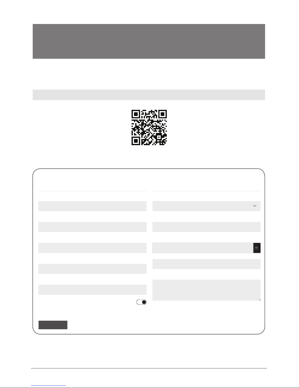
42
GR
Ονοματεπώνυμο*
Διεύθυνση*
Τ.Κ.*
Τηλέφωνο*
Διεύθυνση email*
Vor-und Nachname*
Adresse*
Postleitzahl*
Rufnummer*
E-mail*
Τύπος μηχανήματος*
Σειριακός αριθμός μηχανήματος*
Ημερομηνία αγοράς μηχανήματος*
Αριθμός παραστατικού*
Επιπλέον στοιχεία
Να εγγραφώ στο newsletter της Inventor
Στοιχεία ιδιοκτήτη Στοιχεία μηχανήματος
Για να ενεργοποιήσετε την εγγύηση, παρακαλούμε συμπληρώστε τα παρακάτω πεδία
Υποβολή Εγγύησης
l Επισκεφθείτε τη σελίδα μας και ενεργοποιήστε την εγγύησή σας μέσω
του παρακάτω link ή σκανάροντας το QR code
https://www.inventoraircondition.gr/egiisi-inventor
l Συμπληρώστε όλα τα πεδία όπως φαίνονται παρακάτω
þ
Μόλις ολοκληρωθεί η υποβολή της εγγύησης θα λάβετε την επιβεβαίωση
κατοχύρωσης στο email σας
* Απαραίτητο πεδίο
Αποστέλοντας τη φόρμα εγγύησης αποδέχεστε τους όρους και τις προϋποθέσεις.
AΠΟΣΤΟΛΗ

RO
43
Cuprins
Atentionari ........................................................................................................................................................... 44
Avertizari (la utilizarea agentului frigoric R32/R290) ............................................................................... 46
Preparation .......................................................................................................................................................... 51
Instalare ................................................................................................................................................................ 52
Operare ................................................................................................................................................................ 55
Mentenanta ......................................................................................................................................................... 58
Diagnoza ............................................................................................................................................................... 59
Note despre design si conformitate ............................................................................................................. 60
Remarca Sociala ................................................................................................................................................. 61

44
RO
|Atentionari
AVERTIZARE: Acest simbol indica pericol de ranire sau deces.
AVERTIZARE: Respectati urmatoarele instructiuni, pentru a preveni daunele materiale,
ranirea sau moartea. Utilizarea incorecta sau ignorarea instructiunilor pot produce pagube
materiale sau moarte.
- Instalarea trebuie efectuata urmand strict aceste instructiuni. O instalare incorecta a produsului
poate duce la scurgeri de apa, electrocutare sau pericol de incendiu.
- La instalare, folositi accesoriile disponibile in colet. Folosirea altor accesorii poate cauza caderea
unitatii, scurgeri de apa, electrocutare sau incendii..
- Asigurati- va ca priza pe care o veti folosi corespunde din punct de vedere al tensiunii, este
impamantata corect si ca este protejata de o siguranta ce corespunde cerintelor aparatului.
Informatii despre tensiune gasiti pe placuta aparatului. Va rugam sa apelati la un electrician
autorizat pentru instalarea prizei.
- Instalati doar intr- un loc stabil si capabil sa suporte greutatea aparatului. In caz contrar, aparatul
poate cadea si poate cauza vatamari corporale.
- Asigurati- va ca uxul de aer (atat pe admisie cat si pe evacuare), nu este obstructionat. Astfel, veti
evita aparitia incendiilor.
- Nu modicati lungimea cablului de alimentare si nu folositi prelungitoare. Nu folositi acelasi
stecher si pentru alte aparate electrocasnice. Pericol de incendiu sau electrocutare.
- Nu folositi o singura priza pentru alimentarea mai multor aparate electrocasnice. Pericol de
incendiu sau de electrocutare.
- Nu instalati aparatul intr- o camera cu umiditate ridicata, precum baia sau spalatoria. Expunerea
prelungita la apa, poate cauza socuri electrice/scurtcircuitarea instalatiei.
- Nu instalati aparatul intr- o incapere in care poate expus la gaze combustibile. Pericol de
incendiu!
- Aparatul este echipat cu roti pentru a facilita mutarea sa. Asigurati- va ca nu folositi rotile pe
covor si nu incercati sa treceti cu rolele peste alte obiecte, puteti cauza rasturnarea si deteriorarea
aparatului.
- NU FOLOSITI un aparat care a fost scapat sau deteriorat.
- Asigurati cel putin 1m spatiu liber in jurul aparatului echipat cu dispozitiv electric de caldura.
- Nu atingeti aparatul cu mainile ude sau atunci cand sunteti descult.
- Daca aparatul a fost rasturnat in tipul utilizarii, opriti- l si scoateti- l din priza imediat. Inspectati
vizual unitatea pentru a va asigura ca nu este deteriorate. Daca suspectati ca aparatul a fost
deteriorate, contactati un technician autorizat sau vanzatorul.
- In timpul unei furtuni cu fulgere, opriti alimentarea aparatului cu energie electca, pentru a evita
deteriorarea aparatului.
- Aparatul dumneavoasgtra de aer conditionat va folosit astfel in cat sa e protejat de umiditate
(condens, stropi de apa, etc.). Nu folositi si nu depozitati aparatul in apropierea unei surse de apa
sau alte lichide. In cazul in care aparatul a fost stropit, opriti- l si scoateti- l din priza imediat.
- Cablajul trebuie efectuat respectand diagrama de cablare, disponibila in interiorul unitatii.
- Placa de baza a acestui aparat este echipata cu o siguranta de protectie la supratensiune.
Specicatiile sunt inscrise pe placa astfel: T3.15A/250V, etc.

RO
45
|Atentionari
ATENTIONARI
- Acest aparat poate folosit de copiii de peste 8 ani şi de catre persoane cu capacitati
zice,senzoriale sau mentale reduse, sau lipsite de experienta şi cunoştinte daca li se acorda
supraveghere sau instruire cu privire la utilizarea în siguranta si daca inteleg riscurile implicate.
Copiii nu trebuie lasati să se joace cu acest aparat.Curatarea şi intretinerea nu trebuie efectuate
de catre copii fara supraveghere. (aplicabil in Uniunea Europeana).
- Daca ati deteriorate cablul de alimentare, acesta va inlocuit doar de catre producator, unitatea
de service agreata de acesta sau de alte persoane calicate, pentru a evita pericolele asociate cu
aceasta lucrare.
- Inainte de curatarea sau intretinerea aparatului, scoateti- l din priza.
- Nu incercati sa inlaturati partile/capacele xe. Nu folositi aparatul daca acesta a fost deteriorat,
scapat sau nu functioneaza corect.
.- Nu treceti cablul de alimentare pe sub covoare. Nu acoperiti cablul de alimentare cu paturi,
carpete sau alte materiale. Nu treceti cablul de alimentare pe sub mobilier. Aranajati cablul de
alimentare astfel incat sa nu calcati sau sa va impiedicati de el.
- Nu folositi aparatul daca priza, cablul de alimentare sau siguranta sunt deteriorate. Inlocuiti
aparatul sau duceti- l intr- o unitate de service pentru examinare/reparare.
- Nu folositi ventilatorul impreuna cu un dispozitiv solid pentru controlul vitezei.
- Instalati aparatul, respectand normele nationale cu privire la cablare.
- Pentru repararea sau intretinerea aparatului, contactati service- ul autorizat.
- Pentru instlaarea aparatului, contactati un instalator autorizat.
- Nu obstructionati si nu acoperiti prizele de admisie/evacuare a aerului.
- Nu folositi aparatul in alte scopuri decat cele descrise in acest manual.
- Daca aparatul scoate fum sau simtit mirosuri ciudate, provenite din aparat, scoateti- l din priza
imediat.
- Butoanele de pe panoul de control vor apasate doar cu degetu.
- Nu opriti aparatul prin scoaterea stecherului din priza.
- Nu folositi substante chimice daunatoare pentru curatarea aparatului. Nu folositi aparatul in
prezenta substantelor inamabile sau vapori de alcool, insecticide, benzina, etc.
- Aparatul va transportat, intotdeauna in pozitie verticala si va montat pe o suprafata stabile,
neteda si solida.
- Atunci cand scoateti stecherul din priza, tineti stecherul cu o mana si priza cu cealalta mana, apoi
trageti de stecher usor.
- Daca nu folositi aparatul, opriti- l.

46
RO
|Avertizari (la utilizarea agentului frigoric R32/R290)
- Nu accelerati procesul de degivrare si nu folositi alte produse de curatare, fata de cele
recomandate de producator.
- Depozitati aparatul intr- o incapere fara surse continue de scanteie/caldura (acara deschisa, un
aparat ce functioneaza cu gaz sau incalzitor electric).
- Nu strapungeti si nu ardeti aparatul.
- Atentie! Agentii frigorici pot inodori.
- Aparatul 12000 Btu/h, va instalat intr- o incapere cu o suprafata de cel putin 11 m
2.
- Aparatul 10000 Btu/h, 9000 Btu/h va instalat intr- o incapere cu o suprafata de cel putin 10 m
2
.
- Aparatul 12000 Btu/h,10000 Btu/h va instalat intr- o incapere cu o suprafata de cel putin 12 m
2
.
- Respectati normele nationale cu privire la instalarea aparatelor cu gaz.
- Gurile de admisie/evacuare aer nu vor obstructionate.
- Aparatul va depozitat astfel incat sa se evite deteriorarea acestuia.
- Aparatul va utilizat/depozitat intr- o incapere bine aerisita, care respecta cerintele cu privire la
suprafata.
- Doar persoanele autorizate vor repara aparatul si vor acesa traseul frigoric.
- Lucrarile de service vor efectuate cu respectarea recomandarilor producatorului. Lucrarile de
reparatie si mentenanta vor executate doar de catre personal autorizat pentru lucrul cu agenti
frigorici inamabili.
NOTA IMPORTANTA: Cititi cu atentie acest manual,
inainte de instalarea si operarea aparatului
dumneavoastra de aer conditionat. Pastrati
manualul pentru consultari ulterioare.
Atentie: Pericol de
incendiu / materiale inamabile
(Valabil pentru unitatile cu R32/R290)
Explicatii pentru simbolurile asate pe unitate (valabil pentru unitatile ce folosesc freon R32/R290):
AVERTIZARE Acest simbol semnica faptul ca aparatul foloseste agent frigoric
inamabil. In cazul unei scurgeri de freon, incendiul poate aparea in cazul
in care, in incapere, este prezenta o sursa de scanteie
ATENTIE Acest simbol semnica faptul ca manualul trebuie citit cu atentie.
ATENTIE Acest simbol va atentioneaza ca instalarea si manevrarea aparatului se
vor face doar de catre personal autorizat, in conformitate cu manualul de
instalare.
ATENTIE Acest simbol va adduce la cunostiinta ca informatia va este pusa la
dispozitie, prin manualul de urilizare si manualul de instalare.

RO
47
1. Transportul echipamentului ce contne
agenti frigorici inamabili. Regulile vor
expuse mai jos.
2. Semnalizarea echipamentelor cu
ajutorul simbolurilor. Va rugam sa consultati
regulamentul local.
3. Eliminarea echipamentului ce foloseste
freon inamabil. Va rugam sa consultati
regulamentul national
4. Depozitarea aparatelor se va face
respectand instructiunile producatorului.
5. Depozitarea echipamentelor impachetate
(nevandute) se va face astfel incat produsele
sa nu e deteriorate si pentru evitarea unor
scurgeri de freon. Numarul maxim de unitati
ce pot depozitate impreuna va cel impus de
normele si regulamentele locale.
6. Informare cu privire la service.
1) Vericarile zonei
Inainte de a incepe sa lucrati cu sisteme
ce contin agenti frogirici inamabili, sunt
necesare vericarile de siguranta, pentru a va
asigura ca riscul aprinderii este eliminat. Pentru
pregatirea traseului frigoric, va rugam sa
respectati recomandarile la inceperea oricarei
lucrari asupra sistemului.
2) Procedura
Lucrarea va facuta intr- un mediu controlat,
pentru minimizarea riscului aparitiei gazelor
inamabile sau a vaporilor inamabili
3) Zona de lucru
Toate persoanele prezente in zona lucrarii
trebuie informate cu privire la tipul lucrarii ce
se desfasoara. Lucrarile in spatii inchise trebuie
evitate. Zona din vecinatatea lucrarii trebuie
separate si inchisa. Asigurativa ca respectati
toate conditiile de siguranta.
4) Vericarea incaperii pentru determinarea
prezentei de agent frigoric.
Incaperea in care se vor efectua lucrarile
trebuie vericata cu un dispozitiv pentru
detectarea scurgerilor de freon si pentru a
va asigura ca nu exista surse de substante
inamabile. Asigurati- va ca dispozitivul de
detectare a scurgerilor este corespunzator si
sigur.
5)Prezenta unui extinctor.
Asigurati- va ca veti avea disponibil un extinctor
cu pudra uscata sau CO2, atunci cand lucrati cu
agenti frigorici.
6) Nu exista surse de scanteie.
Persoana ce va lucre la traseul frigoric, ce
include lucrul cu conducte ce contin sau au
continut agent frigoric, nu va folosi dispozitive
sau produse ce pot genera scanteie. Toate
sursele posibile de scanteie, incluzand fumatul,
vor mentinute la o distanta sucienta fata de
locatia in care se instaleaza, repara, inlatura sau
elimina echipamente ce contin agent frigoric.
Inaintea inceperii oricarei actiuni mai sus
prezentate, incaperea va inspectata pentru
a va asigura ca nu exista riscul declansarii unui
incendiu datorita substantelor inamabile. O
pancarta de semnalizare a faptului ca fumatul
este interzis trebuie sa e prezenta.
7) Aerisirea incaperii
Asigurati- va ca incaperea este aerisita corect
inainte de inceperea lucrarilor. Pe tot parcursul
lucrarilor, de asemenea, trebuie asigurata o
sursa de ventilare/aerisire. Sursa de ventilare
trebuie sa elimine agentul refrigerant catre
exterior.
8) Vericarea echipamentului frigoric.
Daca anumite componente electrice au
fost schimbate, asigurati- va ca acestea vor
corespunde specicatiilor actuale. Respectati
ghidul producatorului la ecare pas. Daca
aveti indoieli, consultati departamentul ethnic
al producatorului. Vericarile instalatiilor
ce folosesc agenti frigorici inamabili sunt
urmatoarele:
Incarcarea cu freon se va face in conformitate
cu suprafata incaperii in care se instaleaza
aparatul;
Echipamentul ce asigura ventilarea camerei si
gurile acestuia de evacuare sunt functionale si
ne obstructionate;
Daca se foloseste un traseu frigoric indirect,
vericati si circuitul secundar pentru urme de
freon; Semnalizati echipamentul astfel incat sa
e vizbil si lizibil. Marcajele care mi corespund
vor corectate;
Traseul frigoric si componentele nu vor
instalate intr- o locatie in care pot expuse
substantelor corozive, decat daca acestea sunt
fabricate din materiale ce sunt recomandate
pentru astfel de zone.
9) Vericarile componentelor electro-
mecanice.
Lucrarile de reparative si mentenanta executate
asupra componentelor electro- mecanice,
vor include vericari de siguranta initiale si o
|Avertizari (la utilizarea agentului frigoric R32/R290)

48
RO
|Avertizari (la utilizarea agentului frigoric R32/R290)
inspectie a componentelor respective.
In cazul unei defectiuni, ce poate compromite
siguranta, nici un component nu va conectat la
circuitul electric pana la remedierea defectului.
Daca defectiunea nu poate remediata
imediat dar este absolut necesar ca lucrarea sa
continue, folositi o solutie temporara adecvata.
Aceasta situatie va raportata proprietarului
echipamentului, pentru ca toate partile sa e
informate.
Vericarile initiale pentru siguranta vor include:
Condensatorii sunt descarcati: vericati astfel
incat sa evitati aparitia scanteilor;
Nu exista componente electro- mecanice
alimentate si cablurile nu sunt expuse in timpul
incarcarii cu freon, recuperarii freonului sau
purjarii sistemului;
Vericati continuitatea impamantarii.
7. Repararea componentelor sigiate
1) In timpul lucrarilor executate la componente
sigilate, toate conexiunile electrice vor
deconectate de la echipamentul la care
se executa lucrarea, inainte de inlaturarea
componentelor sigilate, etc. Daca o sursa de
energie electrica este absolut necesara in
timpul service- ului, plasati un echipament
de detectie a scurgerilor in punctul critic al
circuitului, pentru a va avertiza de posibilele
scurgeri si pentru a evita o situatie periculoasa.
intrinsically
2) Acordati atentie speciala si asigurati- va ca nu
veti detriora carcasa aparatului in asa fel incat
sa e afectat nivelul protectiei. Aceata include
deteriorarea cablurilor, un numar mult prea
mare de conexiuni, terminale care nu respecta
specicatiile originale, sigilii deteriorate sau
instalarea incorecta a garniturilor.
Asigurati- va ca aparatul este montat corect.
Asigurati- va ca sigiliile sau materialele
pentru etansare nu sunt deteriorate astfel
incat sa nu isi mai indeplineasca scopul de a
preveni evacuarea de substante inamabile.
Componentele vor inlocuite doar de produse
ce respecta specicatiile producatorului.
NOTA: Folosirea siliconului poate scadea
ecacitatea unor echipamente de detectare a
scurgerilor. Componentele sigure (intrinsec) nu
trebiuesc izolate inainte de a se lucra asupra lor.
8. Reparatia compononentelor sigure
(intrinsec).
Nu aplicati incarcaturi inductive sau capacitive
circuitului, inainte de a va asigura ca acest
fapt nu va depasi tensiunea si amperajul
acceptate de echipament. Componentele
sigure (intrinsec) sunt singurele componente
asupra carora se pot efectua lucrari in medii
inamabile. Echipamentul de testare va asa
valoarea corecta. Componentele vor inlocuite
doar de produse ce respecta specicatiile
producatorului. Folosirea altor produse poate
produce aprinderea freonului.
9. Cablarea
Vericati si asigurati- va ca traseul cablurilor
nu va expus deteriorarii, coroziuni, presiunii
excessive, vibratiilor, marginilor ascutite sau
altor situatii daunatoare. Vericarea trebuie
sa tina cont de efectele “imbatranirii” si
vibratiilor continue produse de surse precum
compresoarele si ventilatoarele.
10. Dectarea agentilor frigorici inamabili
Sursele de scanteie/ama nu vor folosite sub
nici o forma la detectarea scurgerilor. Nu folositi
echipamente cu acara deschisa.
Metode de detectie
Urmatoarele metode sunt acceptate pentru
sistemele ce contin agenti frigorici inamabili:
detectoarele electronice de scurgeri sunt
acceptate insa acuratetea poate neadecvata,
sau va trebui sa e recalibrat (Echipamentele
vor calibrate intr- o incapere in care nu exista
agenti frigorici). Asigurati- va ca detectorul in
sine nu poate o sursa de scanteie si ca este
compatibil cu agentul frigoric folosit. Aparatele
pentru detectia scurgerilor de freon for setate
la un procent LFL al agentului frigoric si vor
calibrate la agentul frigoric pentru care va
folosit si procentajul potrivit (maxim 25%).
Lichidele folosite la detectarea scurgerilor pot
folosite pentru mai multe tipuri de agent
frigoric insa folosirea detergentilor pe baza
de clor este interzisa deoarece clorul poate
reactiona la freon si poate avea proprietati
corozive asupra conductelor de cupru. Daca
suspectati o scurgerge, toate acarile deschise
vor eliminate. Daca descoperiti o scurgere de
freon intr- un loc care necesita lipire/sudare,
recuperati toata cantitatea de refrigerant sau
izolati (prin inchiderea valvelor), inainte de a
incepe lucrarea. Inainte de lipire/sudare si in
timpul procesului, se va folosi Azot fara Oxigen
(OFN), pentru purjarea sistemului.
11. Eliminarea si evacuarea freonului

RO
49
Atunci cand accesati traseul frigoric, pentru
a efectua lucrari sau pentru alte scopuri,
respectati procedurile conventionale. Datorita
amabilitatii agentului frigoric, alegeti cu
atentie cea mai buna solutie pentru situatia
intalnita. Respectati pasii urmatori:
Eliminati agentul frigoric;
Purjati traseul folosing gaze inerte;
Evacuati instalatia;
Purjati inca o data cu gaze inerte;
Accesati traseul frigoric prin taiere.
Agentul frigoric va recuperate in containere
corespunzatoare. Sistemul va incarcat cu
OFN, pentru siguranta. Acest process poate
repetat de cateva ori, in functie de necesitati.
Nu folositi aer comprimat sau oxygen.
Incarcarea instalatiei cu OFN se va face prin
accesarea traseului, pana la atingerea presiunii
de lucru. Dupa ce presiunea de lucru a fost
atinsa, evacuati OFN si vidati instalatia. Repetati
procesul pana cand ati eliminat tot agentul
frigoric din instalatie. La ultima incarcare,
evacuarea se va face pana atingeti presiunea
normala, atmosferica.
Asigurati- va ca evacuarea pompei de vacuum
nu se aa in apropierea unei surse de scanteie.
12. Procedura de incarcare cu freon
Pe langa procedura conventionala de incarcare,
urmatorii pasi vor respectati:
Asoigurati- va ca nu amestecati agenti frigorici
diferiti atunci cand incarcati echipamentul.
Ensure that contamination of dierent
refrigerants does not occur when using
charging equipment. Furtunurile si conductele
vor cat mai scurte, pentru a reduce cantitatea
de agent frigoric continuta de acestea.
Containerele vor tinute in pozitie verticala.
Asigurati- va ca traseul frigoric este
impamantat corect inainte de a incepe
incarcarea.
Daca nu este etichetat, la nalul incarcarii
etichetati corespunzator.
Asigurati- va ca nu supraincarcati sistemul.
Inainte de incarcarea traseului, testate
presiunea cu OFN. Sistemul va testat
impotriva scurgerilor la nalizarea lucrarii,
inainte de punerea in folosinta. Inainte de a
parasi locatia, testati inca o data cu detectorul
de scurgeri.
14.Scoaterea din folosinta
Inainte de inceperea procedurii, este esential ca
tehnicianul sa se familiarizat cu echipamentul,
cunoscand sistemul in detaliu. Recuperati
agentul frigoric in deplina siguranta. Inainte de
incepere, se vor preleva mostre de ulei si agent
frigoric, pentru a determina daca acestea pot
refolosite. Asigurati- va ca exista alimentare cu
energie electrica.
a) Familiarizati- va cu echipamentul.
b) Izolati sistemul din punct de vedere electric.
c) Inainte de a incepe asigurati- va ca: dispuneti
de un system mecanizat de manevrare a
containerelor pentru freon, daca este nevoie;
Echipamentul de protectie este disponibil
si folosit corect; Procesul de reuperare este
supravegheat de o persoana competenta;
Echipamentul de recuperare si containerele
respecta standardele.
d) Daca este posibil, pompati sistemul.
e) Daca vidarea nu este posibila, creati un
sistem de colectare a freonului din diferite parti
ale traseului.
f) Asigurati- va ca recipientele pentru colectare
sunt cantarite inainte de recuperare.
g) Porniti dispozitivul de recuperare,
respectand instructiunile producatorului.
h) Nu supraincarcati recipientele. (volumul nu
va depasi 80%)
i) Nu depasiti presiunea nominala a
containerului, nici macar temporar.
j) Dupa nalizarea colectarii, asigurati- va
ca atat echipamentul de colectare cat si
containerele, vor inlaturate din incapere si ca
toate supapele echipamentului sunt inchise.
k) Agentul frigoric recuperat nu va folosit
intr- un alt sistem decat dupa ce a fost curatat si
vericat.
15.Etichetarea
Echipamentul va etichetat corect, anuntand ca
a fost scos din utilizare si golit de freon. Eticheta
va contine data si semnatura. Asigurati-
va ca exista, de asemenea, si etichete ce
semnalizeaza faptul ca echipamentul foloseste/
contine substante inamabile.
16.Recuperarea
Atunci cand eliminati freonul dintr- un sistem,
atat in vederea lucrarilor de service cat si pentru
scoaterea din uz a aparatului, se recomanda
sa respectati regulile conventionale, pentru
inlaturarea in siguranta.
La incarcarea containerelor, asigurati- va ca
recipientele sunt cele recomandate pentru tipul
|Avertizari (la utilizarea agentului frigoric R32/R290)

50
RO
de freon recuperate.
Asigurati- va ca aveti suciente containere
pentru intreaga cantitate de freon recuperate
din sistem.
Toate containerele sunt destinate tipului
de freon recuperat si vor etichetate
corespunzator (ciilindrii freon recuperat).
Containerele vor echipate cu supape de
reglare a presiunii si supape de inchidere.
Inainte de a incepe procesul de recuperare,
containerele vor golite si racite.
Echipamentul ce urmeaza a golit, trebuie
sa e in stare buna de functionare, sa vina
cu instructiuni si sa e compatibil cu agenti
frigorici inamabili. De asemenea, asigurati- va
ca ati calibrat cantarul si ca este pregatit pentru
folosire. Furtunurile vor vericate impotriva
scurgerii si vor echipate cu racorduri anti
scurgere.
Inainte de folosirea echipamentului de
recuperare, vericati ca este functional, ca a
fost intretinut corect si ca toate componentele
electro- mecanice sunt entanse, pentru a
preveni aparitia unei scantei in cazul unei
scurgeri de freon. Daca aveti dubii, consultati
producatorul.
Freonul recuperate va returnat furnizorului
in containere corespunzatoare, cu nota de
transfer aferenta. Nu amestecati agentii
frigorici in containere. In cazul in care veti
inlatura si uleiul compresorului, asigurativa ca acesta a fost inlaturat complet, pentru
a preveni ramanerea agentului frigoric in
lubriant. Procesul de eliminare va inceput
inainte de returnarea compresorului la furnizor.
Pentru accelerarea procesului, se va folosi doar
rezistenta auxiliara a compresorului.
Note cu privire la gazele uorurate
- Gazele orurate sunt gaze ce produc eect
de sera, pastrate in recipiente inchise ermetic.
Pentru mai multe informatii despre tipul si
cantitatea de CO2 (echivalentul in tone) de
gaze cu eect de sera, va rugam sa consultati
eticheta disponibila pe unitate.
- Instalarea, lucrarile de service sau lucrarile
de mentenanta, vor executate doar de catre
persoane autorizate.
- Scoaterea din folosinta sau reciclarea unitatii
se va face doar de catre persoane autorizate.
|Avertizari (la utilizarea agentului frigoric R32/R290)
MODEL A
MODEL B
SCALE 0.500

RO
51
|Preparation
MODEL A
MODEL B
SCALE 0.500
fata spate
spate
panou de control
aps orizontal
(oscilare automata)
maner
(in ambele parti)
Panou
ltru de aer
(in spatele grilei)
priza admisie aer
superioara
priza de scurgere
priza de aer
ltru de aer inferior
priza admisie aer
ltru de aer
(in spatele grilei)
priza de scurgere
(doar pentru pompa
de caldura)
priza de scurgere
(doar pentru pompa
de caldura)
suport cablu
de alimentare
oriciu cablu de alimentare
mufa cablu de alimentare
tavita de scurgere
inferioara
suport cablu
de alimentare
oriciu cablu de alimentare
mufa cablu de alimentare
tavita de scurgere
inferioara
role
priza de scurgere
priza de aer
ltru de aer inferior
priza admisie aer
priza admisie
aer superioara
Vent control

52
RO
50cm
19.7inch
NOTA: Articolele marcate cu * sunt optionale. Pot aparea mici diferente de design.
|Instalare
Alegerea locatiei potrivite
Recomandari de instalare
Locatia in care urmeaza sa instalati aparatul, trebuie sa
respecte urmatoarele recomandari:
- Suprafata pe care se va instala aparatul, trebuie sa e dreapta
si neteda, pentru a reduce zgomotul si vibtatiile.
- Aparatul se va instala in apropierea unei prize cu
impamantare iar tavita de colectare (disponibila in partea din
spate a aparatului) trebiue sa e accesibila.
- Permiteti un spatiu liber de cel putin 30cm (12”), in jurul
aparatului.
- Nu acoperiti prizele de admisie/evacuare aer sau receptorul
de semnal pentru telecomanda.
NOTA:
Toate imaginile din acest manual au scop informativ. Aparatul
achizitionat pe care l- ati achizitionat poate usor diferit. Forma
aparatului pe care il detineti va prevala.
Aparatul poate controlat atat de la panoul de control cat si
cu ajutorul telecomenzi. Acest manual nu include un ghid de
utilizare al telecomenzii. Pentru informatii cu privire la utilizarea
telecomenzii, va rugam sa consultati ghidul de utilizare a
telecomenzii, disponibil in cutia aparatului.
Atunci cand exista diferente semnicative intre “Manualul de
utilizare” si “Manualul de utilizare al telecomenzii”, descrierea
disponibila in “Manualul de utilizare” va prevala.
Unelte necesare
- Surubelnita in cruce, de marime medie; - Ruleta; - Cutit sau foarfeca; - Fierastrau (optional in cazul
in care trebuie scurtati adaptorul pentru fereastra).
Accesorii
Va rugam sa vericati dimensiunile ferestrei dumneavoastra si sa alegeti adaptorul potrivit.

RO
53
Other Regions
Articol Descriere
Cantitate
Adaptor
1 pc
Furtun evacuare
1 pc
*
Adaptor fereastra
1 pc
*
Adaptor pentru evacuare
prin perete (valabil doar
pentru evacuare prin perete)
1 pc
*
Adaptor evacuare pentru
perete - B (cu capac) (doar
pentru instalarea pe perete)
1 pc
*
Surub si ancora
(pentru instalarea pe perete)
4 set
*
Glisiera fereastra A
1 pc
*
Glisiera fereastra B
1 pc
Centura cablu alimentare
1 pc
Articol Descriere
Cantitate
*
Surub
1 pc
*
Balama cu surub
1 set
Furtun de scurgere
1 pc
Adaptor pentru furtunul de
scurgere (valabil doar pentru
pompa de caldura)
1 pc
*
Garnitura A (Non- Adeziv)
2 pc
*
Garnitura Β (Adeziv)
2 pc
*
Garnitura C (Adeziv)
1 pc
ON/OFF
TEMP
SHORT
CUT
TIMER
ON
TIMER
OFF
MODE
FAN
SLEEP
SWING
LED
Telecomanda si baterie
1set
NOTA: Articolele marcate cu * sunt optionale.
Pot aparea mici diferente de design.
|Instalare
or
MODEL A
MODEL A
MODEL B
MODEL B
Kit pentru instalare la fereastra
Pasul 1: Pregatirea ansamblului de evacuare.
Impingeti furtunul de evacuare in adaptorul pentru
ferastra pana se aude un clic.
Pasul 2: Conectati ansamblul de evacuare la unitate.
Introduceti adaptorul conductei de evacuare in
canelura inferioara a prizei de evacuare. Respectati
indicatiile si asamblati conform sagetilor directionale.
Pasul 3: Pregatiti glisiera ajustabila pentru fereastra
Ajustati glisiera in functie de dimensiunile ferestrei.
1. Daca lungimea ferestrei necesita 2 glisiere, xati
glisierele cu suruburi, dup ace au fost ajustate conform
cerintelor.
2. In cazul anumitor modele, daca lungimea ferestrei
necesita o a treia glisiera (optionala), xati glisierele in
cate 2 suruburi, dupa ce au fost ajustate.
Apasati
Surub
Surub
Surub
Surub
Glisiera A
Glisiera A
Glisiera A
Glisiera A
Glisiera B
Glisiera B
Glisiera B
Glisiera B
Glisiera C
Glisiera C
Adaptor glisiera fereastra
Apasati
Furtun evacuare
Asigurati- va ca ati aliniat clemele adaptorului cu
gura de evacuare si conexiunea este etansa
Oriciu clema
Clema
adaptor
Canelura
inferioara
Asigurati- va ca adaptorul este
introdus corect in canleura
inferioara a gurii de evacuare
Ansamblu
evacuare
sau
sau

54
RO
MODEL A
MODEL B
CL OS E
OP EN
max 120cm or 47 inch
min 30cm or 12 inch
Panoul de control pentru grila de ventilare este
locat in spatele aparatului de aer conditionat.
Pozitia OPEN va ajuta la inlaturarea aerului
invechit din incapere. Aerul proaspat va
absorbit si distribuit in incapere. Atunci cand
nu este nevoie de recircularea aerului, butonull
va sta in pozitia CLOSE. Aceasta functie este
valabila doar pentru modelul B.
|Instalare
Nota: Dup ace ati asamblat furtunul de
evacuare si glisierele pentru fereastra, puteti
alege una dintre cele doua tipuri de instalare.
Tipul1: Fereastra normala sau glisanta
(optional)
1. Taiati garnitura din spuma A si B, in fasii cu
lungimea de care aveti nevoie si xati- le de
tocul ferestrei, asa cum va este demonstrat.
2. Introduceti ansamblul de glisiere in
deschiderea ferestrei.
4. Daca doriti, montati balamaua de securitate, cu
ajutorul a 2 surburi, asa cum va este demonstrat.
5. Conectati adaptorul la glisiera.
3. Taiati garnitura non- adeziva C, intr- o
fasie care sa aibe aceasi latime cu fereastra.
Introduceti garniture intre geam si toc, pentru a
preveni accesul aerului sau al insectelor.
Tip 2. Evacuare prin perete.
1. Decupati o gaura in perete, de 125mm (4.9
inch), pentru a instala adaptorul B pentru
evacuarea prin perete.
2. Fixati adaptorul B cu ajutorul suruburilor si
diblurilor, disponibile in kit.
3. Conectati ansamblul de evacuare (Adaptorul
A), cu adaptorul B.
NOTA: Pentru a asigura functionarea corecta
a aparatului, NU prelungiti sau indoiti furtunul.
Asigurati- va ca furtunul si gura de evacuare
nu sunt obstructionate si au un spatiu liber
de 500mm, imprejur pentru ca sistemul de
evacuare sa functioneze corect. Toate ilustratiile
din acest manual au doar scop informativ.
Aparatul dumneavoastra de aer conditionat
poate usor diferit. Forma aparatului
dumneavoastra va prevala.
Nota: Oriciul va
acoperit cu capacul
disponibil, atunci cand
nu este folosit.
Garnitura B
(mai scurta - adeziva)
Garnitura B
(mai scurta - adeziva)
Pozitia diblulu
Adaptor B
Garnitura A
(adeziva)
Glisiera B
Glisiera B
Glisiera
slider A
Garnitura C
(Non- adeziv)
Balama
2 suruburi
2 suruburi
Security
Bracket
Garnitura C
(Non- adeziv)
Glisiera slider A
Garnitura A
(adeziva)
sau
sau
sau
sau
sau
sau
Capac

RO
55
|Operare
NOTA: La unele modele, simbolul , va asat in loc de °F. Pentru unele modele, simbolul
(indicator wireless), va asat in locul indicatoului luminos de alimentare.
NOTA: ION, FOLLOW ME, WIRELESS nu sunt disponibile. Functia de IONIZATOR nu este disponibila
pentru unitatile cu R32/R290.
Idicator luminos mod HEAT
Indicator luminos mod COOL
Indicator luminos mod FAN
Indicator luminos mod DRY
Indicator luminos mod AUTO
Indicator luminos Wireless
Indicator luminos HIGH - viteza
cea mai mare a ventilatorului
Indicator luminos - MED - viteza
medie a ventilatoruliu
Indicator luminos - LOW - viteza
cea mai mica a ventilatorului
Indicator luminos AUTO - setarea
automata a turatiei ventilatorului
Indicator luminos
- mementor ltre
Indicato luminos - managementul alimentarii
NOTA: Panoul de control va arata precum de mai jos:
Indicator luminos ION
- ionizator
Indicator luminos SLEEP
- functia sleep
Indicator temperatura
- grade Celsius
Indicator temperatura- grade
Fahrenheit
Asaj LED
Indicator luminos functia
FOLLOW ME

56
RO
|Operare
Buton oscilare aps
Folositi- l pentru activarea functiei de oscilare
automata a apsurilor. In timpul oscilarii,
apasati inca o data butonul SWING pentru a
bloca apsul in pozitia dorita.
Buton Timer
Se utilizează pentru inițierea timpului de
pornire AUTO ON și Programul de timp de
oprire AUTO OFF, în conjucție cu butoanele
+ & -. Timerul este pornit / oprit indicatorul
luminos se aprinde sub cronometru setări
on / o.
Butonul MODE
Selecteaza modul de functionare potrivit.
De ecare data cand butonul este apasat,
un mod va selectat intr urmatoarea
ordine:
AUTO, COOL, DRY, FAN si HEAT
(numai modele de răcire fără). I
Indicatorul
LED corespunzator ecarui mod se va
aprinde.
Butoanele SUS (UP, +) si JOS (DOWN, - )
Vor folosite pentru ajustarea temperaturii
(cresterea/scaderea temperaturii), in
trepte de 1 grad Celsius/1grad Fahrenheit
(sau 2 grade Fahrenheit), in intervalul 17
grade celsius/62 grade Fahrenheit si 30 de
grade celsius/86 Fahrenheit, sau setarile
teporizatorului, in intervalul 0- 24 ore.
NOTA: Display- ul LED va asa temperatura
in Fahrenheit sau Celsius, in functie de
cum va setat. Pentru algere, tineti apsate
butoanele UP si DOWN timp de 3 secunde.
Butonul FAN
Apasati butonul pentru a selecta turatia
ventilatorului, in 4 trepte - LOW, MED
HIGH si AUTO. Indicatorul luminos se
va aprinde in dreptul treptei selectate.
La selectarea treptei AUTO, indicatorul
luminos se va stinge. La anumite modele,
toate indicatoarele treptelor de turatie ale
ventilatorului se vor aprinde, atunci cand se
activeaza treapta AUTO.
Butonul SLEEP (ECO)
Apasati butonul pentru a activa functia
SLEEP/ECO.
Butonul POWER
Porneste sau opreste unitatea.
Asaj LED
Aseaza temperatura in grade Celsius sau
Fahrneheit si setarile temporizatorului. In
timpul activarii modurilor DRY si FAN, acesta
va asa temperatura incaperii.
Aseaza erorile:
E1- Eroare a senzorului de temperatura
intern
E2- Eroare a senzorului de temperatura al
evaporatorului
E3- Eroare a senzorului evaporatorului (la
anumite modele)
E4- Eroare de comunicare a asajului
EC - Detectarea unei scurgeri de freon
P1 - Tavita colectoare inferioara este plina
- Conectati furtunul de scurgere si goliti
apa. Daca eroarea se repeta, contactati
departamentul de service.
NOTA: In cazul unei defectiuni, opriti
aparatul si vericati daca exista obstructii.
Reporniti unitatea si daca eroarea persista,
opriti aparatul din nou si scoateti-l din priza.
Contactati producatorul sau reprezentantul
de service.
Instalarea furtunului de evacuare.
Furtunul de evacuare va instalat sau
inlaturat respectand modul de utilizare
recomandat de producator.
Pentru modurile de functionare COOL,
HEAT (pentru aparatele cu pompa de
caldura) sau AUTO, veti instala furtunul de
evacuare.
Pentru modurile FAN, DRY sau HEAT
(incalzire electrica), inlaturati furtunul de
evacuare.

RO
57
Instructiuni de operare
Modul COOL
- Apasati butonul MODE pana cand indicatorul
din dreptul modului "COOL"se aprinde.
- Apasati butoanele de reglare "+" si "-"
pentru a alege temperatura incaperii.
Temperatura poate aleasa intre valorie
17°C~30°C/62°F~88°F(sau 86°F).
- Apasati butonul "FAN SPEED" pentru a selecta
viteza ventilatorului.
Modul HEAT (nu este valabil la aparatele doar cu racire).
- Apasati butonul MODE pana cand indicatorul luminos
din dreptul modului HEAT se aprinde.
- Folositi butoanele pentru ajustare "+" sau "- " pentru
a alege temperatura dorita. Aceasta poate aleasa in
intervalul 17/30 grade celsius (62/86 grade Fahrenheit).
- Apasati butonul "FAN SPEED" pentru a stabili turatia
ventilatorului.
La anumite modele, turatia ventilatorului nu poate
modicata in timpul functionarii modului HEAT.
Modul DRY
- Apasati butonul MODE pana cand indicatorul luminos
din dreptul modului DRY se aprinde.
- In timpul functionarii acestui mod nu puteti modica
turatia ventilatorului sau temperatura. Ventilatorul va
functiona pe treapta cea mai scazuta (LOW).
- Pentru a obtine cele mai bune rezultate, tineti usile si
ferestrele inchise.
- Nu atasati furtunul de evacuare la fereastra.
Modul AUTO
- Atunci cand programati aparatul in modul AUTO,
acesta va selecta automat racirea, incalzirea (doar la
aparatele cu incalzire) sau modul fan, in functie de
conditiile din incapere.
- Aparat va controla temperatura incaperii automat.
- In timpul modului AUTO, nu puteti modica turatia
ventilatorului.
NOTA: In timpul functionarii in AUTO, la anumite
modele, se vor aprinde atat led- urile de semnalizare
AUTO cat si cel de alimentare.
Modul FAN
- Apasa butonul "MODE" pana cand led-ul
indicator "FAN" se aprinde.
- Apasati butonul "FAN SPEED" pentru a selecta
nivelul vitezei ventilatorului. Temperatura nu
poate schimbata.
- Nu atasati furtunul de evacuare la fereastra.
Programarea temporizatorului
- Atunci cand unitatea este pornita, apasati butonul
TIMER si acesta va initia functia AUTO- o, si indicatorul
TIMER OFF se va aprinde. Apasati butonul UP (+) pentru
a selecta perioada dorita. Apasati butonul TIMER inca
o data, in maxim 5 secunde, si modul AUTO- on se va
activa, led- ul corespunzator aprinzandu- se.
Apasati butoanele +/- pentru a programa perioada
dorita.
Functia SLEEP (ECO)
Apasati butonul si temperatura selectata va creste
(in modul racire) sau va scadea (in modul incalzire), in
trepte de 1ºC/2ºF, dupa 30 de minute. Temperatura va
creste/scadea iarasi cu 1ºC/2ºF, dupa alte 30 de minute.
Aceasta noua temperatura va mentinuta pentru 7
ore, dupa aceasta perioada, temperatura setata de
catre dvs. revenind. NOTA: Aceasta functie nu este
disponibila in modul FAN sau DRY
Other features
AUTO- RESTART
In the event of power loss the unit will regain operation,
once power resumes, with the last settings.
Directionarea uxului de aer
Flapsul poate ajustat automat astfe:
- Cand aparatul este pornit, apsul se va deschide
complet.
- Apasati butonul SWING pentru a activa functia de
auto- oscilare a apsului. Acesta va oscila in directia Sus/
Jos automat.
- NU AJUSTATI FLAPSUL MANUAL!
|Operare

58
RO
SCALE 0.500
SCALE 0.500
SCALE 0.500
X
√
delivery lift <1.8m
ASTEPTATI 3 MINUTE PANA LA REPORNIRE
Dupa ce unitatea a fost oprita, aceasta nu va
putea repornita in primele 3 minute. Acesta
este un sistem de protectie
.
MANAGEMENTUL ALIMENTARII Atunci cand, pe o
perioada indelungata, temperatura incaperii este mai
mica decat temperatura programata, aparatul v- a
activa automat functia de management. Compresorul
si ventilatorul se vor opri. Atunci cand temperatura
incaperii trece peste valoarea setata, aparatul va
dezactiva automat functia de management iar
compresorul si ventilatorul vor porni.
NOTA: Cat timp functia de management va activata,
led- ul corespunzator va sta aprins.
Drenajul apei
- In timpul procesului de dezumidicare, inlaturati dopul
de protectie si instalati conectorul pentru scurgere (5/8"
mufa mama), si un furtun 3/4" (achizitionat separat).
Pentru modelele ce nu vin echipate cu un conector
pentru scurgere, conectati furtunul direct la gura de
scurgere. Plasati capatul celalalt al furtunului de-asupra
scurgerii din podea/baie.
- In timpul incalzirii cu pompa de incalzire, inlaturati
dopul de scurgere inferior din spatele unitatii si
instalati conectorul de scurgere (5/8 mama), cu
furtunul 3/4 (achizitionat separat). Pentru modelele
fara adaptor, atasati furtunul direct la aparat.
NOTA: Asigurati-va ca furtunul este montat corect
si ca nu exista scurgeri. Furtunul va indreptat catre
punctul de scurgere si va veti asigura ca pe intreaga
lungime a furtunului, nu exista indoituri sau obstacole
ce vor impiedica scurgerea apei. Cand furtunul nu
este folosit, asigurati-va ca dopul este instalat corect,
pentru evitarea scurgerilor..
- Cand nivelul apei din tavita colectoare atinge un
nivel predeterminat, aparatul va emite un semnal
acustic, consecutiv, de 8 ori iar panoul
va asa mesajul "P1". Procesul de
racire/dezumidicare va incheiat insa
ventilatorul va continua sa functioneze
(este un proces normal). Mutati
unitatea cu grija, catre locul in care
veti putea elimina apa, inlaturati dopul
inferior si lasati apa sa se scurga. Reinstalati dopul si
reporniti unitatea pana cand mesajul "P1" dispare.
Daca eroarea se repeta, contactati departamentul de
service.
NOTA: Asigurati-va ca dopul a fost instalat corect,
pentru a evita scurgerile.
|Mentenanta
AVERTIZARE:
- Intotdeauna opriti si scoateti aparatul din priza,
inainte de a incepe lucrarile de curatare sau service.
- NU FOLOSITI lichide sau substante inamabile
pentru curatarea aparatului.
- NU spalati aparatul cu apa. Pericol de
electrocutare.
- NU folositi aparatul daca, in timpul curatarii,
ati deteriorat sursa de alimentare. Cablul de
alimentare deteriorat va inlocuit cu unul nou, de la
producator.
Curatarea ltrului de aer
ATENTIE
NU folositi aparatul fara sa reinstalati ltrul,
deoarece mizeria si scamele acumulate vor
reduce drastic performata aparatului.
|Operare
SCALE 0.500
SCALE 0.500
Remove the air filter
MODEL A
MODEL B
MODEL A
MODEL B
MODEL A
MODEL B
√ √
SCALE 0.500
√
√
SCALE 0.500
SCALE 0.500
SCALE 0.500
X
√
delivery lift <1.8m
MODEL A
MODEL B
SCALE 0.500
√
√
SCALE 0.500
SCALE 0.500
SCALE 0.500
X
√
delivery lift <1.8m
SCALE 0.500
MODEL A
MODEL B
SCALE 0.500
SCALE 0.500
SCALE 0.500
X
√
delivery lift <1.8m
Inlaturati ltrul de aer
Filtru
superior
Scoateți șa
superioară
de golire
Scoateți șa
superioară
de golire
Scoateți șa
superioară
de golire
Scoateți șa
superioară
de golire
Furtun de
scurgere
continuu
Furtun de
scurgere
continuu
Furtun de
scurgere
continuu
Furtun de
scurgere
continuu
Filtru
superior
Lowe air
lter
Scoateți
șurubul,
apoi scoateți
ltrul pentru
jgheab
Adaptor
pentru
furtunul de
scurgere
Adaptor
pentru
furtunul de
scurgere
Apăsați catarama
cablului de
alimentare în
capacul din spate
Adaptor pentru
furtunul de
scurgere
Adaptor pentru
furtunul de
scurgere

RO
59
|Mentenanta
Sfaturi pentru mentenanta
- Curatati ltrul o data la 2 saptamani, pentru a
mentine performantele aparatului.
- Tavita de colectare a apei trebuie sa e golita
imediat dupa asarea mesajului "P1".
- Daca aveti animale de companie, curatati grilele
aparatului periodic, pentru a evita acumularea
parului.
Curatarea unitati
Curatati unitatea cu ajutorul unei carpe umede,
fara scame si folosind un detergent delicat.
Uscati aparatul cu ajutorul unei carpe uscate,
fara scame.
Depozitarea aparatului cand nu este folosit.
- Goliti tavita de colectare a apei si resp
instructiunile de mai jos:
- Mentineti aparatul in modul FAN timp de 12
ore, pentru o uscare completa, eliminand astfel
posibilitatea aparitiei mucegaiului.
- Opriti aparatul si scoateti- l din priza.
- Curatati ltrul respectand instructiunile oferite
in sectiunea precedenta. Reinstalati ltrul curat
dupa ce a fost uscat complet.
- Scoateti bateriile din telecomanda.
Asigurati- va ca unitatea va pastrata intr- o
incapere racoroasa, fara lumina. Expunerea la
lumina solara sau temperaturi extreme, a scurta
perioada de utilizare a aparatului.
NOTA: Carcarsa si partea frontala pot sterse
cu o carpa uscata sau curtate cu o carpa umezita
si cu un detergent de vase delicat. Clatiti bine
si stergeti pana aparatul este uscat complet.
Nu folositi detergenti duri, ceara sau substante
pentru polish. Stoarceti bine carpa inainte de a
o folosi pentru stergerea butoanelor. Pericol de
deteriorare a aparatului.
|Diagnoza
Inainte de a solicita service, va rugam sa vericati erorile de mai jos:
Problema Cauza posibila Solutia
Aparatul nu
porneste atunci
cand este apasat
butonul ON/OFF
Eroare P1 Tavita de colectare a apei s- a umplut.
Opriti aparatul, goliti tavita, reinstalatio si reporniti aparatul.
In modul COOL: temperatura
incaperii este mai mica decat
temperatura selectata.
Resetati temperatura
Aparatul nu este
ecient la racire
Aparatul este infundat cu praf sau
par de animal.
Opriti aparatul si curatati ltrul
conform instructiunilor.
Furtunul de evacuare nu este
conectat sau este blocat.
Opriti aparatul, deconectati furtunul
si vericati pentru eventuale blocaje.
Dupa nalizare, reinstalati furtunul.
Cantitatea de agent frigoric este
scazuta
Apelati la un tehnician autorizat
pentru a inspecta aparatul si pentru
a- l realimenta cu agent frigoric
Temperatura selectata este prea
mare
Micsorati temperatura selectata
Usile si ferestrele incaperii sunt
deschise
Inchideti ferestrele si usile
Suprafata incaperii este prea mare Vericati inca o data suprafata
Exista surse de caldura in incapere Inlaturati sursele de caldura, daca
este posibil
Unitatea este
zgomotoasa si
vibreaza
Suprafata pe care este asezat
aparatul nu este neteda
Asezati aparatul pe o suprafata
dreapta si neteda
Aparatul este infundat cu praf sau
par de animal
Opriti aparatul si curatati ltrul
conform instructiunilor.
Aparatul scoate
sunete "bolborosite"
Zgomotul este generat de circulatia
freonului prin traseul frigoric
Acesta este un fenomen normal

60
RO
|Note despre design si conformitate
Note despre design:
Aspectul zic si specicatiile tehnice se pot schimba fara o noticare prealabila datorita
imbunatatirii produsului. Pentru mai multe informatii, va rugam sa contactati vanzatorul. Toate
actualizarile acestui manual vor disponibile pe website- ul nostru si va recomandam sa vericati
intotdeauna pentru aparitia unei noi versiuni.
Informatii despre clasicarea energetica
Clasicarea energetica este bazata pe o instalare in care nu a fost folosita o extensie a conductei
de evacuare si fara adaptor pentru fereastra sau adadaptorul pentru perete A (asa cum este asat
in sectiunea de instalare). In acelasi timp, aparatul trebuie programat pe modul COOL si HIGH FAN
SPEED, din telecomanda.
Temperaturi
Mod de functionare Plaja de temperaturi
Racire (Cool) 17- 35°C (62- 95°F)
Dezumidicare (Dry) 13- 35°C (55- 95°F)
HEAT (incalzire cu pompa de
caldura)
5- 30°C (41- 86°F)
HEAT (incalzire cu rezistenta
electrica)
30°C (86°F)
NOTA: Pentru a respecta EN 6100- 3- 11, produsul M2GHP290-12, va conectat doar la un sistem
electric cu impedanta: |Zsys|=0.348 ohmi sau mai mica. Inainte de conectarea produsului la
reteaua electrica, cereti mai multe informatii distribuitorului dumneavoastra de energie electrica,
pentru a va asigura ca reteaua respecta valorile de mai sus. authority to ensure the power network
meet above requirement.

RO
61
Toate imaginile din acest manual, au scop pur informativ. Forma reala a produsului pe care lati cumparat poate usor diferita insa functiile si operatiile sunt aceleasi.
Compania nu isi asuma nici o responsabilitate pentru greselile de tipar. Aspectul zic si
specicatiile tehnice se pot schimba fara o noticare prealabila datorita imbunatatirii continue
a echipamentelor noastre.
Pentru mai multe detalii, va rugam sa contactati producatorul la numarul de telefon : +30 211
300 3300, sau vanzatorul echipamentului. Toate actualizarile acestui manual vor disponibile
pe website- ul nostru si va recomandam sa vericati intotdeauna pentru aparitia unei noi
versiuni.
Scanati codul QR pentru a descarca ultima versiune a manualului.
www.inventoraerconditionat.ro/biblioteca- media
|Remarca Sociala
Atunci cand utilizati acest produs in tarile din Uniunea Europeana, respectati urmatoarele
instructiuni:
Scoaterea din folosinta: Nu aruncati acest produs impreuna cu deseul municipal. Colectarea
acestui produs se face separat.
Este interzisa aruncarea acestui produs impreuna cu deseul casnic.
La eliminarea acestui aparat, respectati urmatoarele aspecte:
A) Autoritatile locare va pun la dispozitie puncte de colectare, in care deseurile electronice pot
lasate gratuit.
B) La cumpararea unui aparat nou, vanzatorul va poate ridica gratuit echipamentul vechi.
C) Producatorul va poate ridica produsul vechi gratuit.
D) Puteti vinde aparatul catre rmele care se ocupa cu colectarea erului vechi.
Aruncarea acestui aparat in padure sau alte locuri din natura, dauneaza mediului inconjurator.
Substantele nocive pot ajunge in panza freatica si in alimente.

Nume complet*
Adresa*
Cod Postal*
Numar de telefon*
E-mail*
Vor-und Nachname*
Adresse*
Postleitzahl*
Rufnummer*
E-mail*
Tip aparat*
Numarul de Serie al aparatului*
Data de achizitie*
Numar Factura*
Detalii aditionale
Abonati-va la Newsletter-ul Inventor
Detalii propietar Detalii unitate
Pentru a activa garantia, va rugam sa completati urmatoarele campuri
Activati-va garantia
l Accesati link-ul de mai jos sau scanati codul QR pentru a va activa
garantia pe site-ul nostru.
https://www.inventoraerconditionat.ro/certicatul-de-garantie-inventor-aer-conditionat-si-electrocasnice
l Completati toate campurile conform exemplului de mai jos
þ
Odata ce garantia a fost activata, veti primi un email de confirmare
* Camp obligatoriu
Cu acest certicat de garantie acceptati Termenii si Conditiile.
TRIMITE

EN
63

64
EN
PORTABLE
AIR CONDITIONING SYSTEMS
v 1.0
 Loading...