

• SERVICE MANUAL
ENGLISH
WALL MOUNTED UNIT
AIR CONDITIONING SYSTEMS
MODELS:
L4VI32-09/L4VO32-09
L4VI32-12/L4VO32-12

Service Manual
Service Manual
Table of Contents
Service Manual
Table of Contents
Part
Ⅰ
: Technical Information
.......................................................................1
1. Summary
......................................................................................................................1
..........................................................................................................2
...........................................................................................................2
2.2 Operation Characteristic Curve ........................................................................................6
2.3 Capacity Variation Ratio According to Temperature ....................................................... ..6
2.4 Cooling and Heating Data Sheet in Rated Frequency .....................................................7
2.5 Noise Curve ......................................................................................................................7
3. Outline Dimension Diagram
........................................................................8
3.1 Indoor Unit ........................................................................................................................8
3.2 Outdoor Unit .....................................................................................................................9
4. Refrigerant System Diagram
....................................................................10
5. Electrical Part
.........................................................................................................11
5.1 Wiring Diagram ...............................................................................................................11
5.2 PCB Printed Diagram .....................................................................................................13
6. Function and Control
......................................................................................15
6.1 Remote Controller Introduction .....................................................................................15
6.2 Preparation before operation..........................................................................................15
6.3 Introduction of operation function ..................................................................................15
6.4 Introduction of special functions ....................................................................................17
6.5 Brief Description of Modes and Functions......................................................................19
Part
Ⅱ
: Installation and Maintenance
.................................................24
7. Notes for Installation and Maintenance
..........................................24
8. Installation
................................................................................................................28
8.1 Installation Dimension Diagram ......................................................................................28
8.2 Installation Parts-checking ............................................................................................30
8.3 Selection of Installation Location ....................................................................................30
8.4 Requirements for electric connection .............................................................................30
8.5 Installation of Indoor Unit ................................................................................................30
8.6 Installation of Outdoor Unit .............................................................................................33
8.7 Vacuum Pumping and Leak Detection ...........................................................................34
8.8 Check after Installation and Test Operation ...................................................................34

Service Manual
Table of contents
Service Manual
9. Maintenance
............................................................................................................74
9.1 Error Code List ...............................................................................................................74
9.2 Procedure of Troubleshooting ........................................................................................82
9.3 Troubleshooting for Normal Malfunction .........................................................................97
10. Exploded View and Parts List
..............................................................99
10.1 Indoor Unit ....................................................................................................................99
10.2 Outdoor Unit ...............................................................................................................109
11. Removal Procedure
..................................................................................... 116
11.1 Removal Procedure of Indoor Unit ............................................................................. 116
11.2 Removal Procedure of Outdoor Unit ..........................................................................126
Appendix:
......................................................................................................................141
Appendix 1: Reference Sheet of Celsius and Fahrenheit ..................................................141
Appendix 2: Conguration of Connection Pipe ...................................................................141
Appendix 3: Pipe Expanding Method .................................................................................142
Appendix 4: List of Resistance for Temperature Sensor ....................................................143
Technical Information
1
Service Manual
Service Manual
Part
Ⅰ
: Technical Information
1. Summary
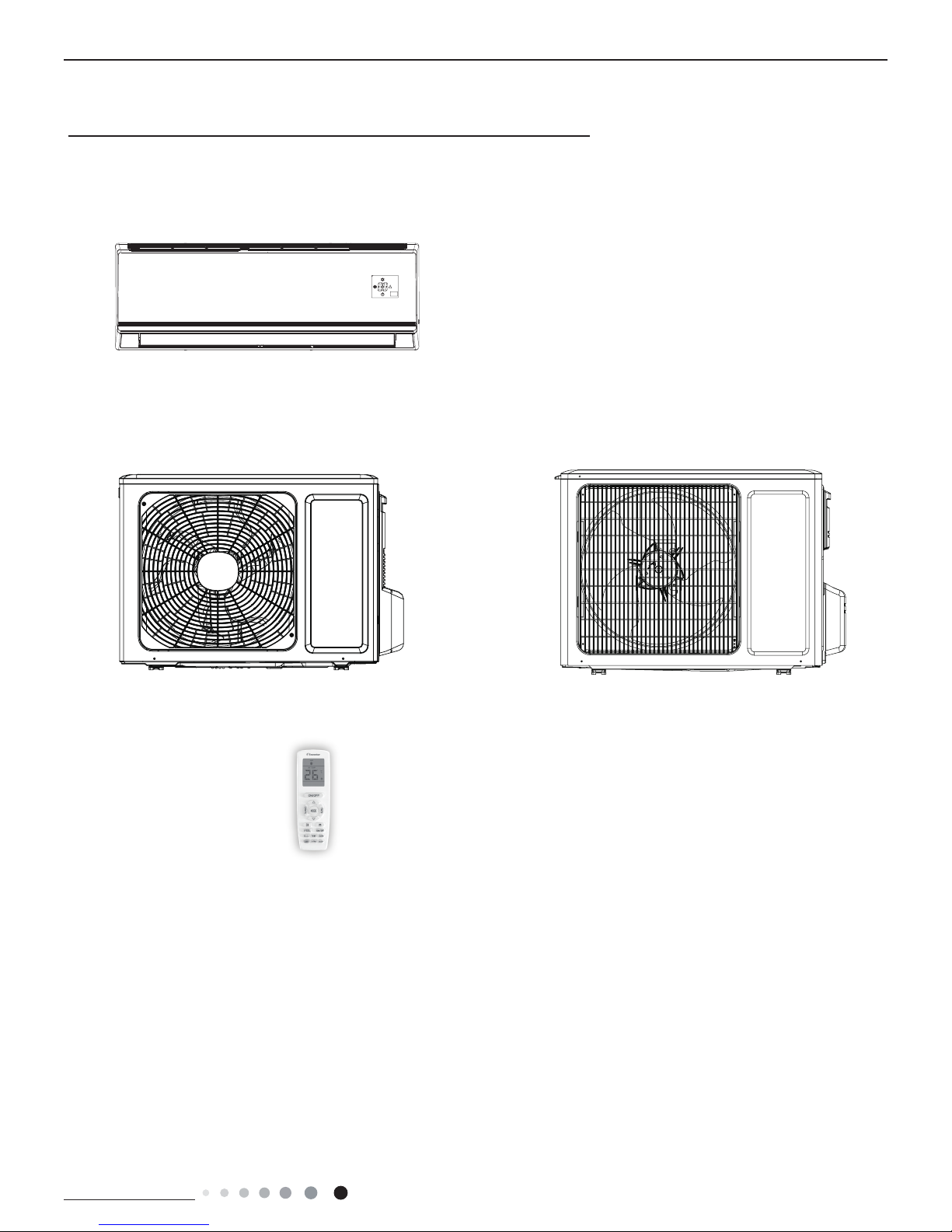
Indoor Unit
L4VI32-09, L4VI32-12
Outdoor Unit
L4VO32-09 L4VO32-12
Remote Controller
YAN1F1
Technical Information
2
Service Manual
Service Manual
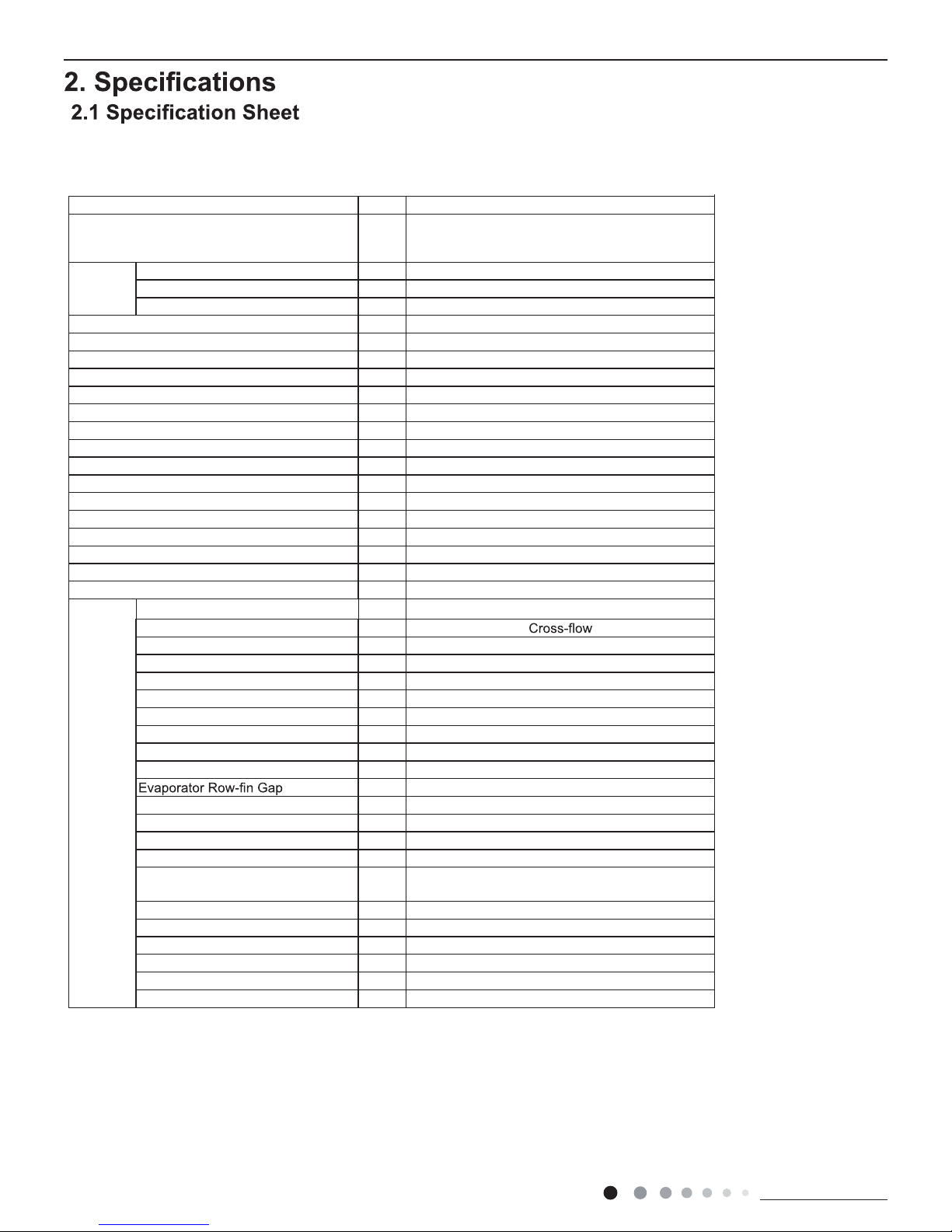
Parameter Unit Value
Model L4VI32-09
Power
Supply
Rated Voltage V~ 220-240
Rated Frequency Hz 50
Phases 1
Power Supply Mode Outdoor
Cooling Capacity(Min~Max) W 2600(500~3350)
Heating Capacity(Min~Max) W 2800(500~3500)
Cooling Power Input(Min~Max) W 805(160~1400)
Heating Power Input(Min~Max) W 755(200~1500)
Cooling Current Input A 3.9
Heating Current Input A 3.4
Rated Input W 1500
Rated Current A 6.3
Air Flow Volume(SH/H/M//L/SL) m
3
/h 560/490/430/330/Dehumidifying Volume L/h 0.8
EER W/W 3.23
COP W/W 3.71
SEER W/W 6.1
SCOP(Average/Warmer/Colder) W/W 4.0/5.1/3.2
Application Area m
2
12-18
Indoor
Unit
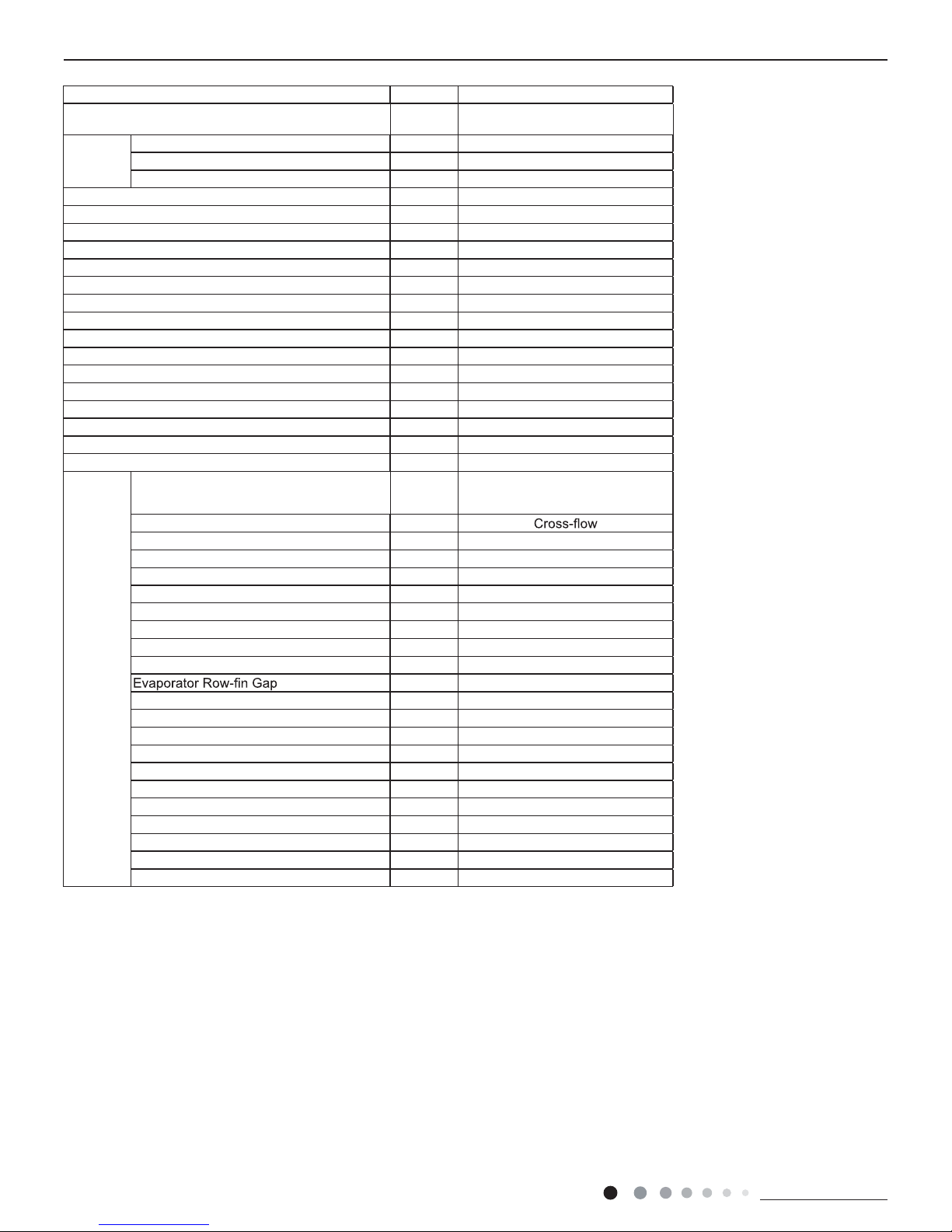
Indoor Unit Model L4VI32-09
Fan Type
Fan Diameter Length(DXL) mm Ф98X580
Cooling Speed(SH/H/M//L/SL) r/min 1300/1200/1050/800/Heating Speed(SH/H/M//L/SL) r/min 1300/1200/1050/900/Fan Motor Power Output W 20
Fan Motor RLA A 0.215
Fan Motor Capacitor μF 1
Evaporator Form Aluminum Fin-copper Tube
Evaporator Pipe Diameter mm Ф5
mm 2-1.4
Evaporator Coil Length (LXDXW) mm 584X22.8X266.7
Swing Motor Model MP24AA
Swing Motor Power Output W 1.5
Fuse Current A 3.15
Sound Pressure Level(SH/H/M//L/
SL)
dB (A) 39/36/32/28/-
Sound Power Level(SH/H/M//L/SL) dB (A) 55/52/44/38/Dimension (WXHXD) mm 790X275X200
Dimension of Carton Box (LXWXH) mm 863X268X352
Dimension of Package(LXWXH) mm 866X271X367
Net Weight kg 9
Gross Weight kg 11
Technical Information
3
Service Manual
Service Manual
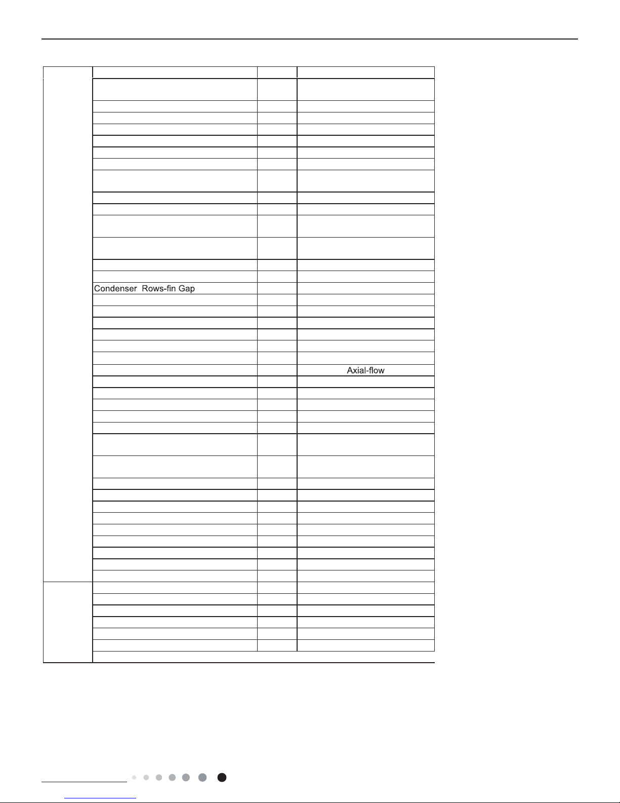
The above data is subject to change without notice. Please refer to the nameplate of the unit.
Outdoor
Unit
Outdoor Unit Model L4VI32-12
Compressor Manufacturer
ZHUHAI LANDA COMPRESSOR
CO.,LTD
Compressor Model QXF-B096zE190A
Compressor Oil FW68DA
Compressor Type Rotary
Compressor LRA. A 20.00
Compressor RLA A 4.21
Compressor Power Input W 943
Compressor Overload Protector
1NT11L-6233 HPC115/95U1
KSD115ºC
Throttling Method Capillary
Set Temperature Range ºC 16~30
Cooling Operation Ambient Temperature
Range
ºC -15~43
Heating Operation Ambient Temperature
Range
ºC -15~24
Condenser Form Aluminum Fin-copper Tube
Condenser Pipe Diameter mm Φ7
mm 1-1.4
Condenser Coil Length (LXDXW) mm 710X19.05X508
Fan Motor Speed rpm 900
Fan Motor Power Output W 30
Fan Motor RLA A 0.36
Fan Motor Capacitor μF /
Outdoor Unit Air Flow Volume m
3
/h 1600
Fan Type
Fan Diameter mm Φ400
Defrosting Method Automatic Defrosting
Climate Type T1
Isolation I
Moisture Protection IPX4
Permissible Excessive Operating
Pressure for the Discharge Side
MPa 4.3
Permissible Excessive Operating
Pressure for the Suction Side
MPa 2.5
Sound Pressure Level (H/M/L) dB (A) 52/-/Sound Power Level (H/M/L) dB (A) 61/-/Dimension(WXHXD) mm 782X540X320
Dimension of Carton Box (LXWXH) mm 820X355X580
Dimension of Package(LXWXH) mm 823X358X595
Net Weight kg 29.5
Gross Weight kg 32
Refrigerant R32
Refrigerant Charge kg 0.6
Connection
Pipe
Connection Pipe Length m 5
Connection Pipe Gas Additional Charge g/m 20
Outer Diameter Liquid Pipe mm Φ6
Outer Diameter Gas Pipe mm Φ9.52
Max Distance Height m 10
Max Distance Length m 19
Note: The connection pipe applies metric diameter.
Technical Information
4
Service Manual
Service Manual
Parameter Unit Value
Model L4VI32-12
Power
Supply
Rated Voltage V~ 220-240
Rated Frequency Hz 50
Phases 1
Power Supply Mode Outdoor
Cooling Capacity(Min~Max) W 3500(800~3700)
Heating Capacity(Min~Max) W 3670(900~380)
Cooling Power Input(Min~Max) W 1085(220~1400)
Heating Power Input(Min~Max) W 990(220~1500)
Cooling Current Input A 5.0
Heating Current Input A 4.5
Rated Input W 1500
Rated Current A 7.2
Air Flow Volume(SH/H/M//L/SL) m
3
/h 680/590/490/420/Dehumidifying Volume L/h 1.4
EER W/W 3.26
COP W/W 3.71
SEER W/W 6.1
SCOP(Average/Warmer/Colder) W/W 4.0/5.1/3.4
Application Area m
2
16-24
Indoor
Unit
Indoor Unit Model L4VI32-12
Fan Type
Fan Diameter Length(DXL) mm Φ98X633.5
Cooling Speed(SH/H/M//L/SL) r/min 1350/1200/1050/850/Heating Speed(SH/H/M//L/SL) r/min 1300/1150/1000/900/Fan Motor Power Output W 20
Fan Motor RLA A 0.31
Fan Motor Capacitor μF 1.5
Evaporator Form Aluminum Fin-copper Tube
Evaporator Pipe Diameter mm Ф5
mm 2-1.5
Evaporator Coil Length (LXDXW) mm 635X22.8X306.3
Swing Motor Model MP24BA
Swing Motor Power Output W 2
Fuse Current A 3.15
Sound Pressure Level(SH/H/M//L/SL) dB (A) 42/38/34/31/Sound Power Level(SH/H/M//L/SL) dB (A) 56/52/48/45/Dimension (WXHXD) mm 845X289X209
Dimension of Carton Box (LXWXH) mm 918X278X364
Dimension of Package(LXWXH) mm 921X281X379
Net Weight kg 10.5
Gross Weight kg 12.5
Technical Information
5
Service Manual
Service Manual
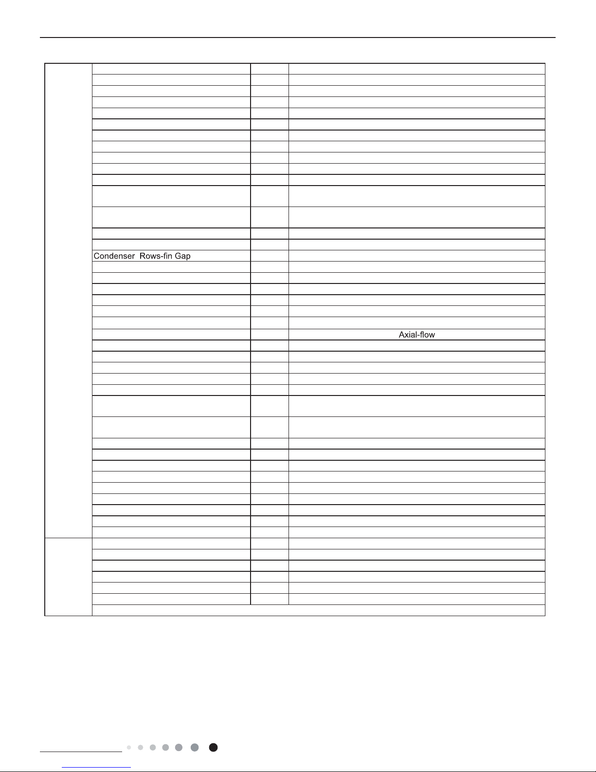
The above data is subject to change without notice. Please refer to the nameplate of the unit.
Outdoor
Unit
Outdoor Unit Model L4VO32-12
Compressor Manufacturer ZHUHAI LANDA COMPRESSOR CO., LTD
Compressor Model QXF-B096zE190A
Compressor Oil FW68DA
Compressor Type Rotary
Compressor LRA. A 20
Compressor RLA A 4.21
Compressor Power Input W 943
Compressor Overload Protector 1NT11L-6233 HPC115/95U1 KSD115ºC
Throttling Method Capillary
Set Temperature Range ºC 16~30
Cooling Operation Ambient Temperature
Range
ºC -15~43
Heating Operation Ambient Temperature
Range
ºC -15~24
Condenser Form Aluminum Fin-copper Tube
Condenser Pipe Diameter mm Φ7.94
mm 1-1.4
Condenser Coil Length (LXDXW) mm 731X19.05X550
Fan Motor Speed rpm 900
Fan Motor Power Output W 30
Fan Motor RLA A 0.36
Fan Motor Capacitor μF /
Outdoor Unit Air Flow Volume m
3
/h 2200
Fan Type
Fan Diameter mm Φ438
Defrosting Method Automatic Defrosting
Climate Type T1
Isolation I
Moisture Protection IPX4
Permissible Excessive Operating
Pressure for the Discharge Side
MPa 4.3
Permissible Excessive Operating
Pressure for the Suction Side
MPa 2.5
Sound Pressure Level (H/M/L) dB (A) 53/-/Sound Power Level (H/M/L) dB (A) 62/-/Dimension(WXHXD) mm 848X596X320
Dimension of Carton Box (LXWXH) mm 878X360X630
Dimension of Package(LXWXH) mm 881X363X645
Net Weight kg 31
Gross Weight kg 34
Refrigerant R32
Refrigerant Charge kg 0.7
Connection
Pipe
Connection Pipe Length m 5
Connection Pipe Gas Additional Charge g/m 20
Outer Diameter Liquid Pipe mm Φ6
Outer Diameter Gas Pipe mm Φ9.52
Max Distance Height m 10
Max Distance Length m 20
Note: The connection pipe applies metric diameter.

Technical Information
6
Service Manual
Service Manual
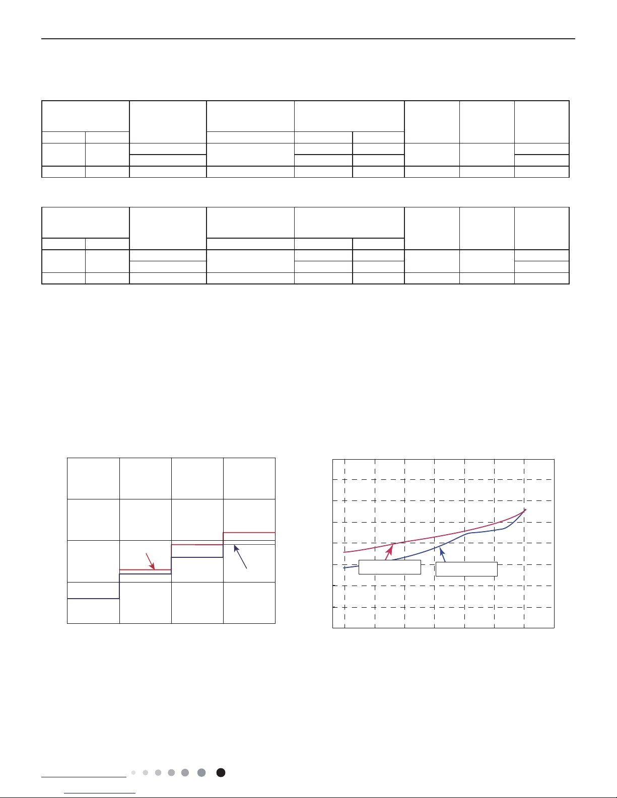
2.2 Operation Characteristic Curve
2.3 Capacity Variation Ratio According to Temperature
gnitaeHgnilooC
50
60
70
80
90
100
110
120
130
32 33 34 35 36 37 38 39 40 41 42 43 44 45 46
Capacity ratio(%)
Outdoor temp. (°C)
Capacity ratio(
%)
–15 –10 –5
110
100
90
80
70
60
50
40
0 5 7 10
Conditions
Indoor:DB20°C
Indoor air flow:Super High
Pipe length:5m
Outdoor temp.(°C)
Condition
Indoor:DB27°C WB19°C
Indoor air flow:
High
Pipe length:5m
Heating operation ambient temperature range is -15ºC~24ºC
0 10 20 30 40 50 60 70 90 0 10 20 30 40 50 60 70 80 90 100
120
110
80
11
10
9
8
7
6
5
4
3
2
1
0
Compressor speed (rps)
)A(tnerruC
11
10
9
8
7
6
5
4
3
2
1
0
Compressor speed (rps)
)A(tnerruC
220V
230V
240V
220V
230V
240V
Conditions
Indoor: DB27°C/WB19°C
Outdoor: DB35°C/WB24°C
Indoor air flow: High
Pipe length: 5m
Conditions
Indoor: DB20°C/WB15°C
Outdoor: DB7°C/WB6°C
Indoor air flow: High
Pipe length: 5m
Cooling Heating
Technical Information
7
Service Manual
Service Manual
2.4 Cooling and Heating Data Sheet in Rated Frequency
2.5 Noise Curve
Indoor side noise when blowing Outdoor side noise when blowing
Indoor fan motor rotating speed Compressor frequency(Hz)
Noise/dB(A)
50
60
30
40
20
Low
Middle
High
Super High
12K
09K
40
42
44
46
48
50
52
54
56
20 4030 50 60 70 80
90
Noise dB(A)
09&12K Cooling
09&12K Heating
Cooling:
Rated cooling
condition(°C) (DB/WB)
Model
Pressure of gas pipe
connecting indoor and
outdoor unit
Inlet and outlet pipe
temperature of heat
exchanger
Fan speed of
indoor unit
Fan speed of
outdoor unit
Compressor
revolution
(rps)
Indoor Outdoor P (MPa) T1 (°C) T2 (°C)
27/19 35/24
09K
0.8 ~ 1.1
12 to 15 65 to 38
TURBO High
49
12K 11 to 14 64 to 37 60
27/19 35/24 18K 0.9 ~ 1.1 12 to 14 75 to 37 Super High High 52
Instruction:
T1: Inlet and outlet pipe temperature of evaporator
T2: Inlet and outlet pipe temperature of condenser
P: Pressure at the side of big valve
Connection pipe length: 5 m.
Heating:
Rated cooling
condition(°C) (DB/WB)
Model
Pressure of gas pipe
connecting indoor and
outdoor unit
Inlet and outlet pipe
temperature of heat
exchanger
Fan speed of
indoor unit
Fan speed of
outdoor unit
Compressor
revolution
(rps)
Indoor Outdoor P (MPa) T1 (°C) T2 (°C)
20/- 7/6
09K
2.8 ~ 3.2
35 to 63 2 to 5
TURBO High
59
12K 35 to 65 2 to 5 67
20/- 7/6 18K 2.2 ~ 2.4 70 to35 2 to 4 Super High High 65
09/12K
Technical Information
8
Service Manual
Service Manual
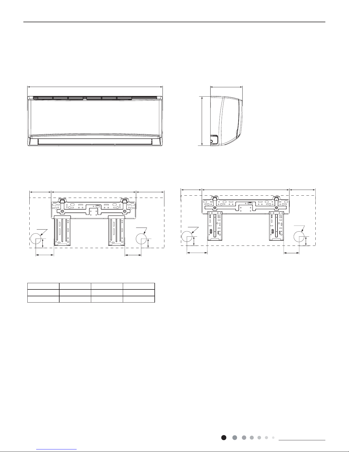
3. Outline Dimension Diagram
3.1 Indoor Unit
Unit:mm
Model W H D
09K 790 275 200
12K 845 289 209
W
12K
09K
D
H
90
150
54
168.5 462 159.5
Φ55
Φ55
54
123.5 542 179.5
83.2
124.7
35
Φ55
Φ55
35
Technical Information
9
Service Manual
Service Manual
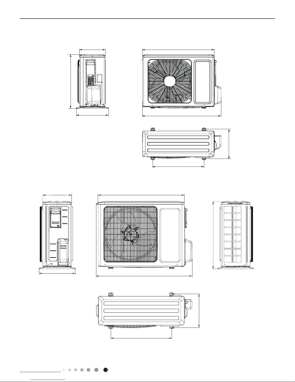
3.2 Outdoor Unit
712
782
257
320
540
286
510
Unit:mm
257
780
596
842
286
540
320
Unit:mm
L4VO32-09
L4VO32-12
Technical Information
10
Service Manual
Service Manual
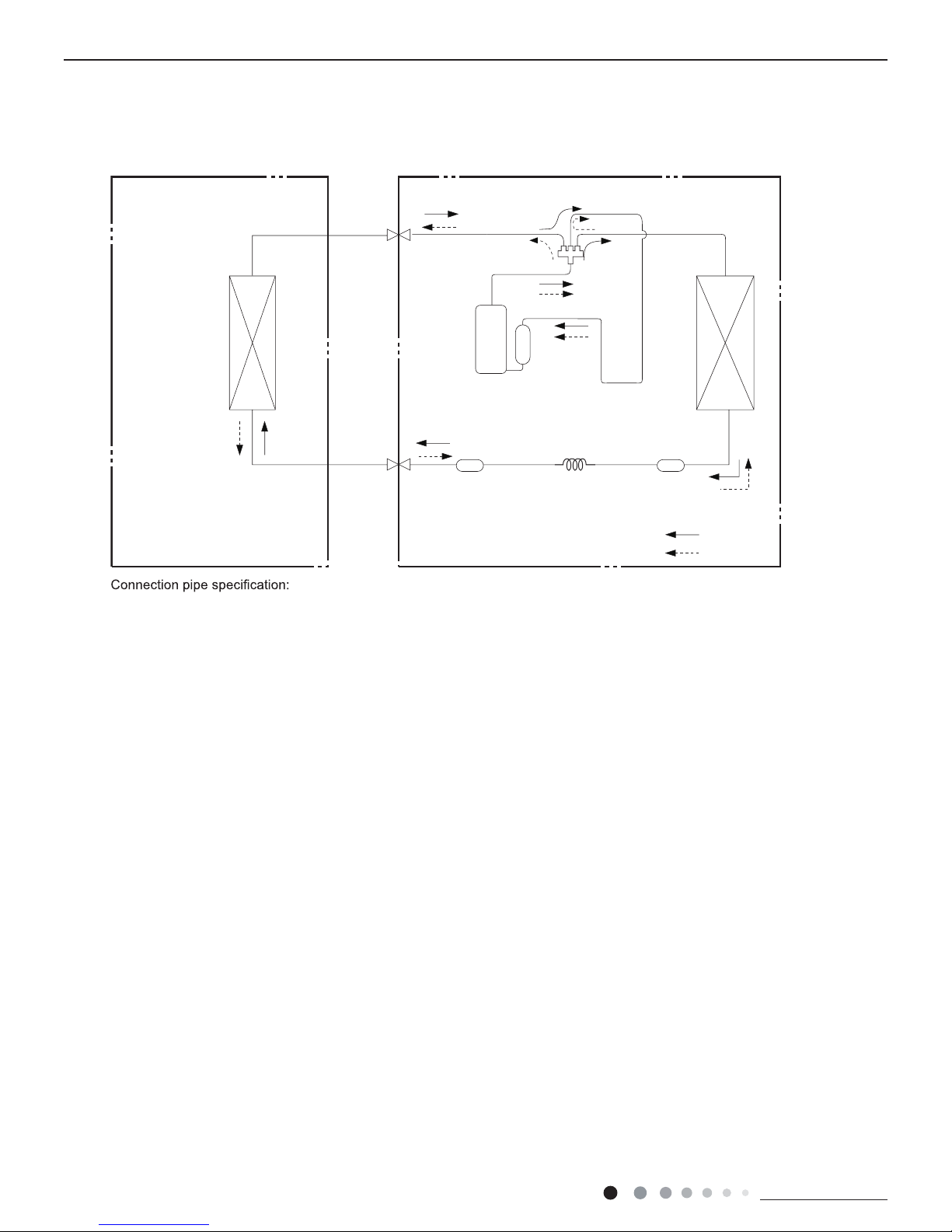
Indoor unit
Outdoor unit
COOLING
HEATING
4-Way valve
Discharge
Suction
Heat
exchanger
(evaporator)
Heat
exchanger
(condenser)
Valve
Valve
Liquid pipe
side
Gas pipe
side
Strainer
Strainer
Capillary
Accumlator
Compressor
4. Refrigerant System Diagram
Liquid pipe:1/4" (6mm)
Gas pipe:3/8" (9.52mm)
09/12K
Technical Information
11
Service Manual
Service Manual
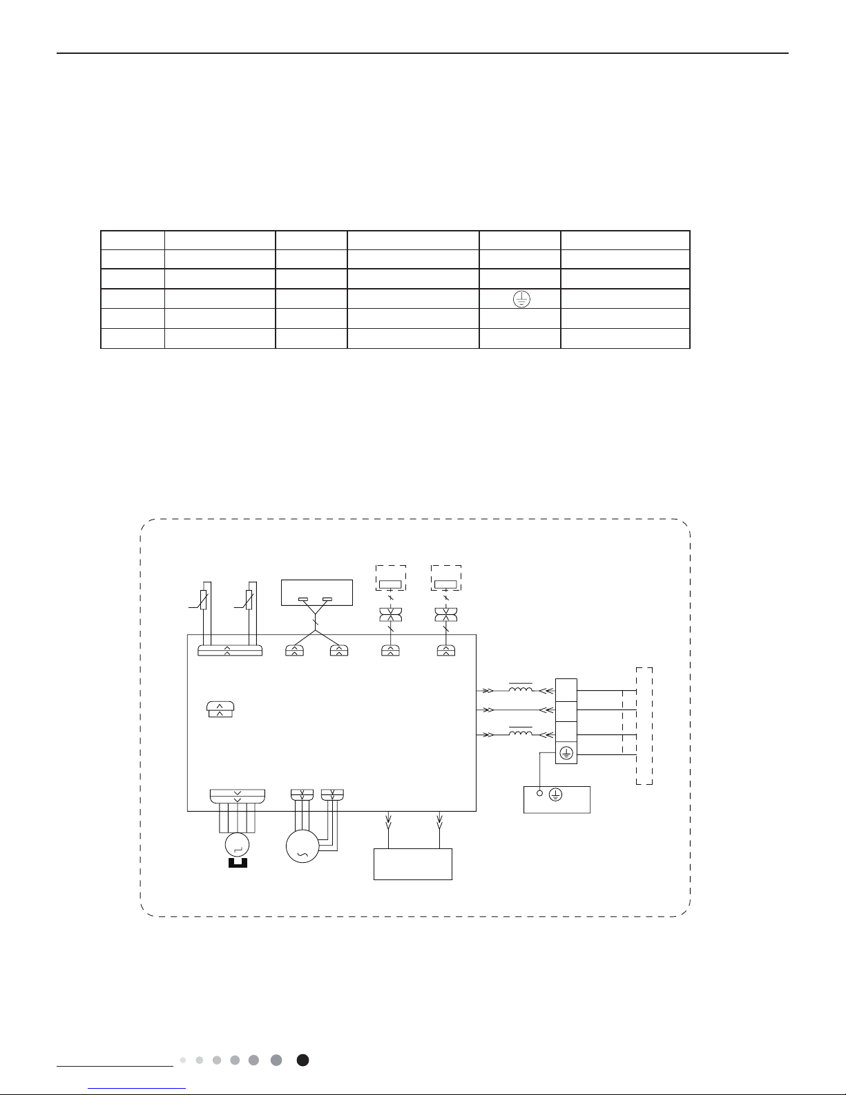
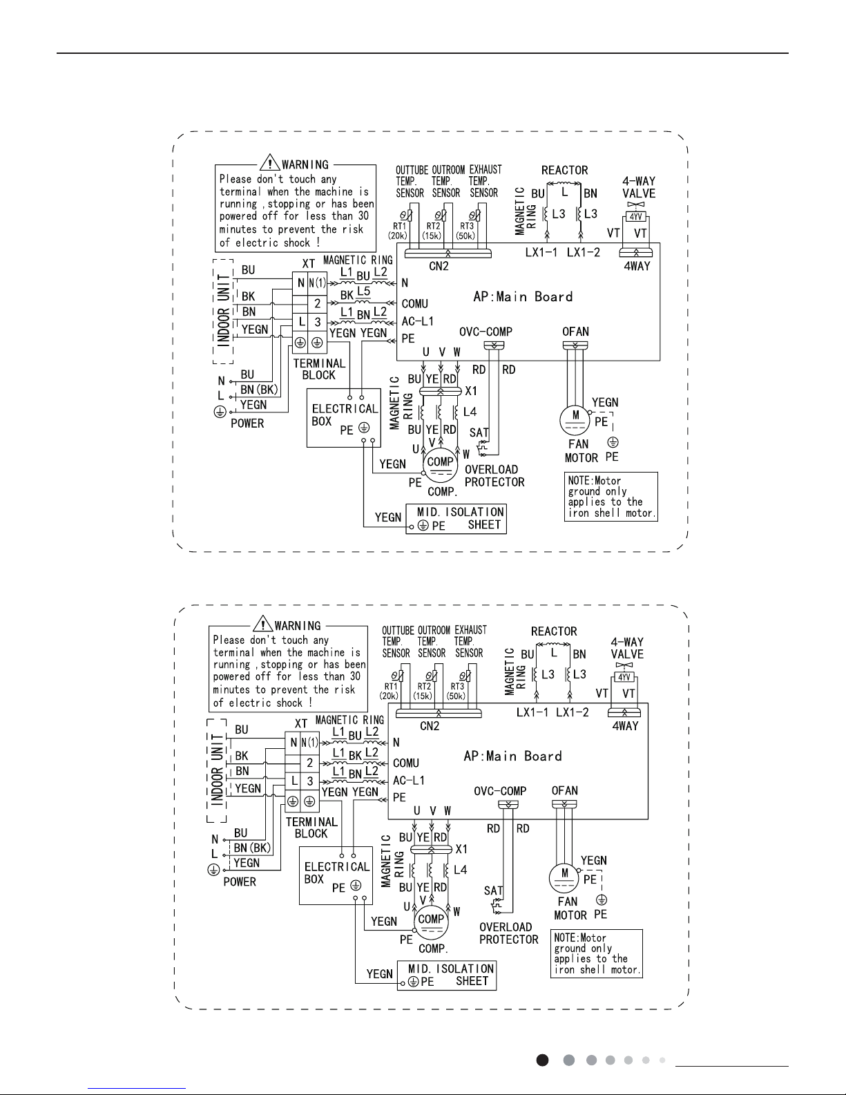
5. Electrical Part
5.1 Wiring Diagram
● Indoor Unit
● Instruction
Symbol Symbol Color Symbol Symbol Color Symbol Name
WH White GN Green CAP Jumper cap
YE Yellow BN Brown COMP Compressor
RD Red BU Blue Grounding wire
YEGN Yellow/Green BK Black / /
VT Violet OG Orange / /
Note: Jumper cap is used to determine fan speed and the swing angle of horizontal lover for this model.
600007000688
:,5('
&21752//(5
&200$18$/
76(1625
7(03
6(1625
7(03
6(1625
57
522078%(
67(33,1*
',63/$<
35,17('&,5&8,7%2$5'
5(&(,9(5$1'
',63/$<%2$5'
&$%/(
&211(&7,1*
6:,1*8'
02725
%/2&.
7(50,1$/
$3
-803
&$3
%8
%.
<(*1
(9$325$725
3(
;7
1
0
287'22581,7
$3
3*
*(1(5$725
&2/'3/$60$
)$102725
0
5' %8
+($/7+1
+($/7+/
3*)
',63 ',63
%1
<(*1
57
1
&20287
$&/
%8
%.
%1
/
/
:,),
02'8/(
:,),
$3
$3
0$*1(7,&
5,1*
L4VI32-09, L4VI32-12
Technical Information
12
Service Manual
Service Manual
● Outdoor Unit
600007000687
L4VO32-09
L4VO32-12
600007000763
Technical Information
13
Service Manual
Service Manual
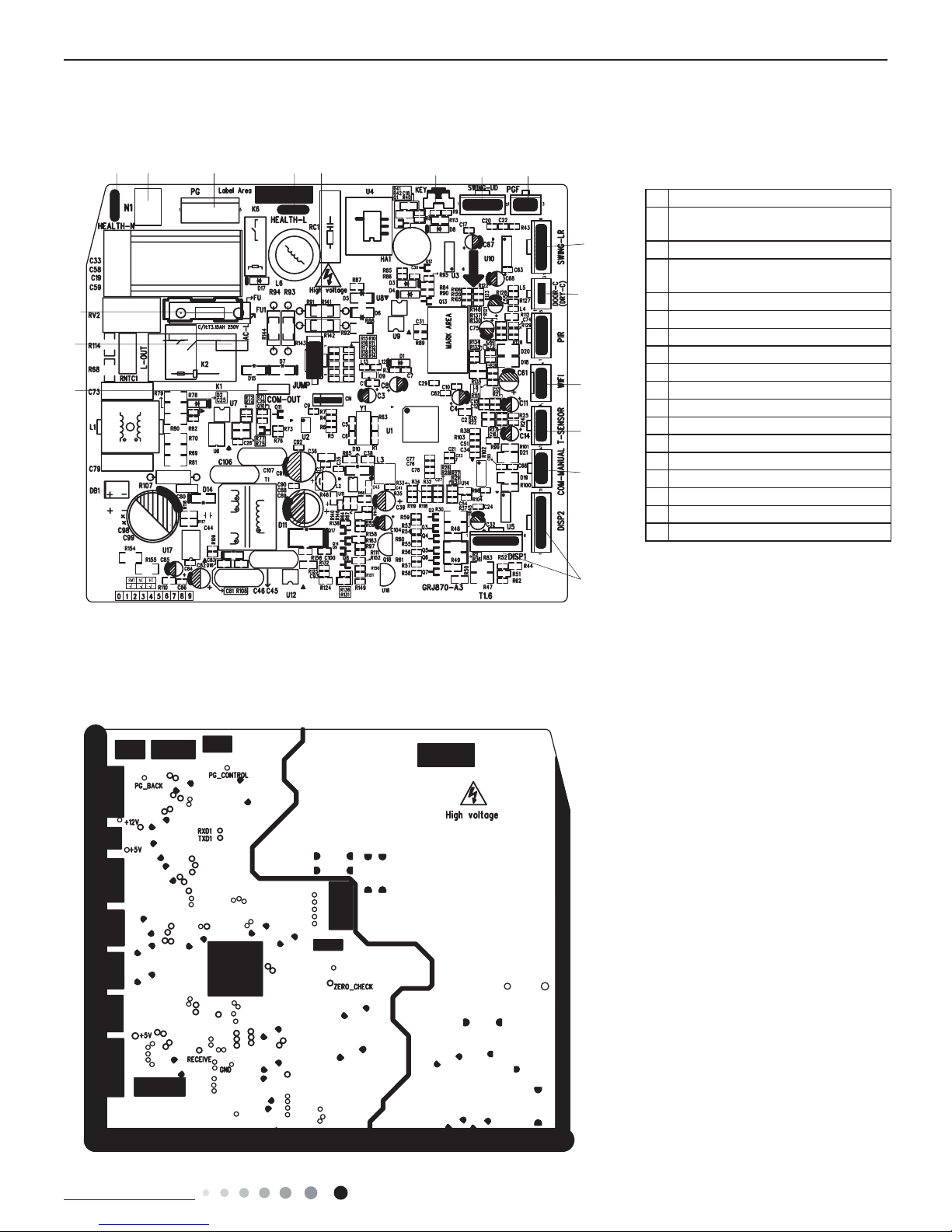
No Name
1
Interface of communication wire for
indoor unit and outdoor unit
2 Interface of live wire
3
Interface of health function neutral
wire
4 Interface of neutral wire
5 Interface of fan
6 Interface of health function live wire
7 Jumper cap
8 Auto button
9 Up&down swing interface
10 Feedback interface of indoor unit
11 left&right swing interface
12 Interface of wi
13 Interface of tube temperature sensor
14 Wired controller
15 Display interface
16 Fuse
17 Terminal for gate control function
5.2 PCB Printed Diagram
Indoor Unit
● Top view
● Bottom view
1
2
16
3 4 5 6
7
8 9 10
11
12
13
14
15
17
Technical Information
14
Service Manual
Service Manual
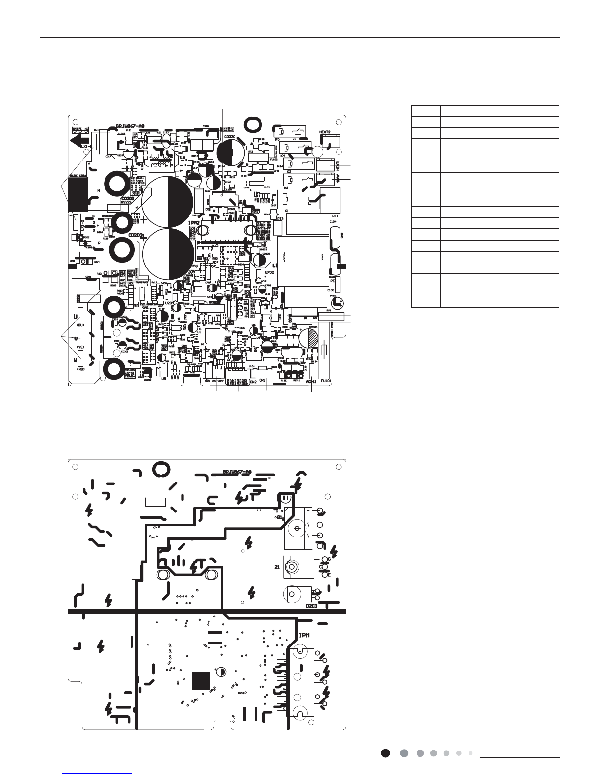
● Top view
● Bottom view
1
2
3 4
5
6
7
8
9
10111213
Outdoor Unit
No. Name
1 Compressor wiring terminal
2 Reactor wiring terminal
3 Outdoor fan wiring terminal
4
Terminal of chassis electric
heater
5
Terminal of compressor
electric heater
6 Terminal of 4-way valve
7 Grounding wire
8 Communication wire
9
Neutral wire
10 Live wire
11
Terminal of electronic
expansion valve
12
Terminal of temperature
sensor
13 Compressor overload terminal
09/12K
Technical Information
15
Service Manual
Service Manual
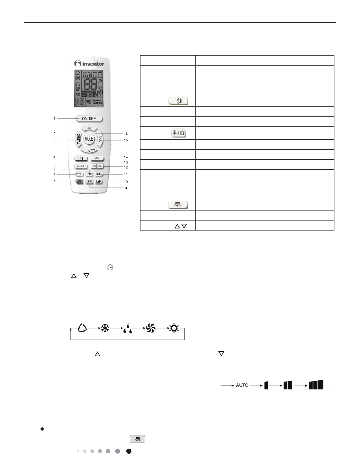
6. Function and Control
6.1 Remote Controller Introduction
No. Button name Function
1 ON/OFF Turn on or turn off the unit
2 TURBO Set turbo function
3 MODE Set operation mode
4
Set up&down swing status
5 I FEEL Set I FEEL function
6 TEMP Switch temperature displaying type on the unit’s display
7
Set health function and air function
8 LIGHT Set light function
9 X-FAN Set X-FAN function
10 SLEEP Set sleep function
11 CLOCK Set clock of the system
12 TOFF Set timer off function
13 TON Set timer on function
14
Set left&right swing status
15 FAN Set fan speed
16 / Set temperature and time
6.2 Preparation before operation
When using the remote controller for the first time or after replacing the batteries,
please set the time of the system according to current time in the following steps:
(1).
Pressing CLOCK button, is blinking.
(2).
Pressing or button, the clock time will increase or decrease rapidly.
(3).
Press CLOCK button again to confirm the time and return to display current time.
6.3 Introduction of operation function
(1).
Selecting operation mode
In unit on status, press MODE button to select operation mode in following sequence:
(2).
Setting temperature
In unit on status, press
button to increase setting temperature and press button to decrease setting temperature. The
Note: Under auto mode, manual adjustment of temperature is not needed.
range of temperature is from 16ºC to 30ºC.
(3).
Adjusting fan speed
In unit on status, press FAN button to adjust fan speed in following sequence:
Notes:
①.
When operation mode changes, fan speed is memoried;
②.
Under dry mode, fan speed is low and can not be adjusted.
(4).
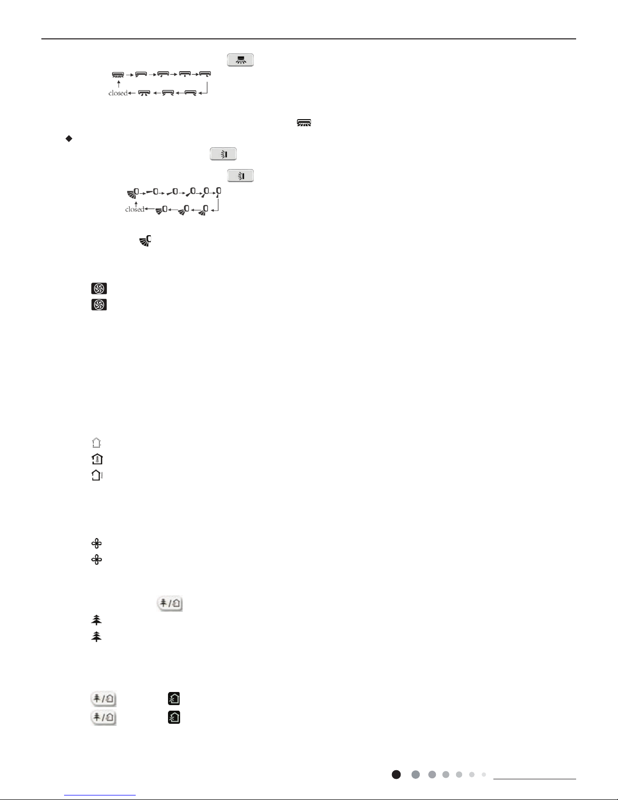
Setting swing function
Setting left&right swing
1).
Under simple swing status, press button to adjust left&right swing status;
Technical Information
16
Service Manual
Service Manual
2).
Under fixed-angle swing status, press button to adjust left&right swing angle circularly as below:
Note: operate continuously left&right swing in 2 seconds, swing states will change
according to above-mentioned order, or switch closed state and
state.
Setting up&down swing
1).
Under simple swing status, press button to adjust up&down swing status;
2).
Under fixed-angle swing status, press button to adjust up&down swing angle circularly as below:
Note: operate continuously left&right swing in 2 seconds, swing states will change according to above-mentioned order, or switch
closed state and state
(5).
Setting turbo function
Under cool or heat mode, press TURBO button to set turbo function.
When
is displayed, turbo function is on.
When
is not displayed, turbo function is off.
When turbo function is on, the unit operates in super high speed to achieve quick cooling or heating. When turbo function is off,
the unit operates in setting fan speed.
(6).
Setting light function
The light on the receiver light board will display present operation status. If you want to turn
off the light, please press LIGHT button. Press this button again to turn on the light.
(7).
Viewing ambient temperature
In unit on status, receiver light board or wired controller is defaulted to display setting
temperature. Press TEMP b
utton to view indoor or outdoor ambient temperature.
When
is displayed, it means the displayed temperature is setting temperature.
When
is displayed, it means the displayed temperature is indoor ambient temperature.
When is displayed, it means the displayed temperature is outdoor ambient temperature.
Note: setting temperature is always displayed in Remote Controller.
(8).
Setting X-FAN function
In cool or dry mode, press X-FAN button to set X-FAN function.
When
is displayed, X-FAN function is on.
When
is not displayed, X-FAN function is off.
When X-FAN function is on, the water on the evaporator will be blown away until turning off the unit to avoid mildew.
(9).
Setting health function
In unit on status, press
button to set health function.
When
is displayed, health function is on.
When
is not displayed, health function is off.
Health function is available when the unit is equipped with anion generator. When health function is on, the anion generator will start
operation, adsorbing the dusts and killing the bacteria in the room.
(10).
Setting air function
Press
button until is displayed, then air function is turned on.
Press
button until is disappeared, then air function is turned off.
When the indoor unit is connected with fresh air valve, air function setting can control the connection of fresh air valve, which can
control the fresh air volume and improve the air quality inside the room.
Technical Information
17
Service Manual
Service Manual
(11).
Setting sleep function
In unit on status, press SLEEP button to turn on or turn off sleep function.
When
is displayed, sleep function is on.
When
is not displayed, sleep function is off.
Notes:
①.
Sleep function can not be set in auto and fan mode;
②.
When turning off the unit or switching mode, sleep function is cancelled;
(12).
Setting I FEEL function
In unit on status, press I FEEL button to turn on or turn off I FEEL function.
When is displayed, I FEEL function is on.
When
is not displayed, I FEEL function is off.
When I FEEL function is turned on, the unit will adjust temperature according to the temperature detected by the remote controller
to achieve the best air-conditioning effect. In this case, you should place the remote controller within the valid receiving range.
(13).
Setting timer
You can set the operation time of unit as you need. You can also set timer on and timer off in combination.
Before setting, check if the time of the system is the same as the current time. If not, please set the time according to current time.
1).
Setting timer off
①.
Pressing TOFF button, “OFF” is blinking and time displaying zone displays the timer time of last setting
②.
Press or button to adjust the timer time.
③.
Press TOFF button again to confirm setting. OFF is displayed and time displaying zone resumes to display current time.
④.
Press TOFF button again to cancel timer and OFF is not displayed.
2).
Setting timer on
①.
Pressing TON button, “ON” is blinking and time displaying zone displays the timer time of last setting.
②.
Press or button to adjust the timer time.
③.
Press TON button again to confirm setting. ON is displayed and time displaying zone resumes to display current time.
④.
Press TON button again to cancel timer and ON is not displayed.
6.4 Introduction of special functions
(1).
Setting child lock
Press
and button simultaneously to lock the buttons on remote controller and is displayed.
Press
and button simultaneously again to unlock the buttons on remote controller and is not displayed.
If the buttons are locked,
blinks 3 times when pressing the button and any operation on the button is invalid.
(2).
Switching temperature scale
In unit off status, press MODE button and
button simultaneously to switch temperature scale between ºC and ºF.
(3).
Setting energy-saving function
In unit on status and under cool mode, press CLOCK and TEMP button
simultaneously to enter energy-saving mode.
u When
is displayed, energy-saving function is on.
u When
is not displayed, energy-saving function is off.
If you want to turn off the energy-saving function, press CLOCK and TEMP button and is not displayed.
Note: energy-saving function is only available in cooling mode and it will be exited when switching mode or setting sleep function.
(4).
Absence function
In unit on status and under heat mode, press CLOCK and TEMP button simultaneously to enter absence function.
Press CLOCK and TEMP button simultaneously again to exit absence function.
Temperature displaying zone resumes previous display and is not displayed.
Temperature displaying zone displays 8 and is displayed.
Technical Information
18
Service Manual
Service Manual
In winter, absence function can keep the indoor ambient temperature above 0ºC to avoid freezing.
Note: Absence function is only available in heating mode and it will be exited when switching mode or setting sleep function.
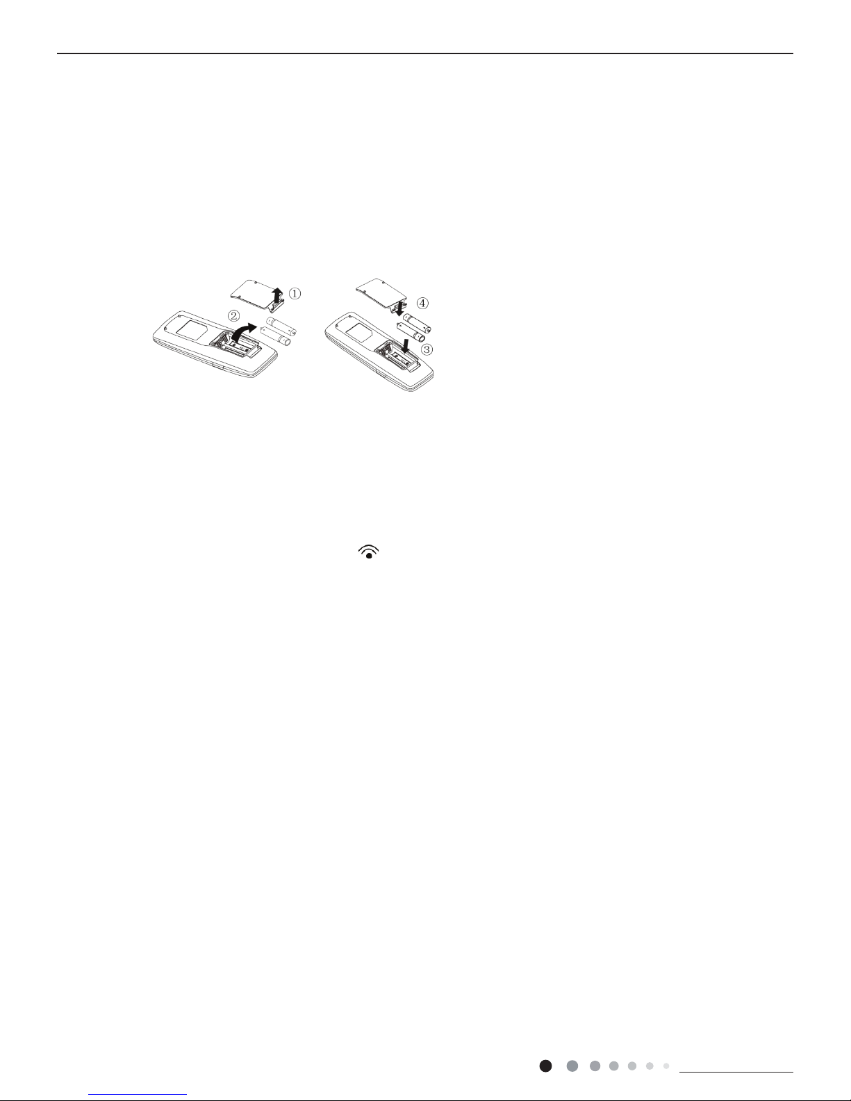
(1).
Lift the cover along the direction of arrow (as shown in Fig 1①).
(2).
Take out the original batteries (as shown in Fig 1②).
(3).
Place two 7# (AAA 1.5V) dry batteries, and make sure the position of “+” polar
and “ -” polar is correct (as shown in Fig 2 ③).
(4).
Reinstall the cover (as shown in Fig 2④).
Fig.1 Fig.2
Notes:
①.
The remote controller should be placed 1m away from the TV set or stereo sound sets.
②.
.egnar gniviecer sti nihtiw demrofrep eb dluohs rellortnoc etomer fo noitarepo ehT
③.
If you need to control the main unit, please point the remote controller at the signal receiving window of the main unit to improve
④.
When the remote controller is sending signal, “ ” icon will be blinking for 1 second. When the main unit receives valid remote
⑤.
If the remote controller does not operate normally, please take the batteries out and reinsert them after 30 seconds. If it still
can't operate properly, replace the batteries.
⑥.
When replacing the batteries, do not use old or different types of batteries, otherwise, it may cause malfunction.
⑦.
.seirettab eht tuo ekat esaelp ,emit gnol a rof rellortnoc etomer eht esu t’now uoy nehW
the receiving sensibility of main unit.
control signal, it will give out a sound

Technical Information
19
Service Manual
Service Manual
6.5 Brief Description of Modes and Functions
1.Basic function of system
(1)Cooling mode
(1) Under this mode, fan and swing operates at setting status. Temperature setting range is 16~30OC.
(2) During malfunction of outdoor unit or the unit is stopped because of protection, indoor unit keeps original operation status.
(2)Drying mode
(1) Under this mode, fan operates at low speed and swing operates at setting status. Temperature setting range is 16~30OC.
(2) During malfunction of outdoor unit or the unit is stopped because of protection, indoor unit keeps original operation status.
(3) Protection status is same as that under cooling mode.
(4) Sleep function is not available for drying mode.
(3)Heating mode
(1) Under this mode, Temperature setting range is 16~30OC.
(2) Working condition and process for heating mode:
When turn on the unit under heating mode, indoor unit enters into cold air prevention status. When the unit is stopped or at OFF status,
and indoor unit has been started up just now, the unit enters into residual heat-blowing status.
(4)Working method for AUTO mode:
1.Working condition and process for AUTO mode:
a.Under AUTO mode, standard heating Tpreset=20OC and standard cooling Tpreset=25OC. The unit will switch mode automatically
according to ambient temperature.
2.Protection function
a. During cooling operation, protection function is same as that under cooling mode.
b. During heating operation, protection function is same as that under heating mode.
3. Display: Set temperature is the set value under each condition. Ambient temperature is (Tamb.-Tcompensation) for heat pump unit
and Tamb. for cooling only unit.
4. If theres I feel function, Tcompensation is 0. Others are same as above.
(5)Fan mode
Under this mode, indoor fan operates at set fan speed. Compressor, outdoor fan, 4-way valve and electric heating tube stop operation.
Indoor fan can select to operate at high, medium, low or auto fan speed. Temperature setting range is 16~30
O
C.
2. Other control
(1) Buzzer
Upon energization or availably operating the unit or remote controller, the buzzer will give out a beep.
(2) Auto button
If press this auto button when turning off the unit, the complete unit will operate at auto mode. Indoor fan operates at auto fan speed
and swing function is turned on. Press this auto button at ON status to turn off the unit.
(3) Auto fan
Heating mode: During auto heating mode or normal heating ode, auto fan speed will adjust the fan speed automatically according to
ambient temperature and set temperature.
(4) Sleep
After setting sleep function for a period of time, system will adjust set temperature automatically.
(5) Timer function:
General timer and clock timer functions are compatible by equipping remote controller with different functions.
(6) Memory function
memorize compensation temperature, off-peak energization value.
Memory content: mode, up&down swing, light, set temperature, set fan speed, general timer (clock timer cant be memorized).
After power recovery, the unit will be turned on automatically according to memory content.
(7) Health function
During operation of indoor fan, set health function by remote controller. Turn off the unit will also turn off health function.
Turn on the unit by pressing auto button, and the health is defaulted ON.
●
Indoor Unit

Technical Information
20
Service Manual
Service Manual
(8)I feel control mode
After controller received I feel control signal and ambient temperature sent by remote controller, controller will work according to the ambient
temperature sent by remote controller.
(9)Entry condition for compulsory defrosting function
When turn on the unit under heating ode and set temperature is 16OC (or 16.5OC by remote controller), press “+, -, +, -, +, -” button
successively within 5s and then indoor unit will enter into compulsory defrosting setting status:
(1) If theres only indoor units controller, it enters into indoor normal defrosting mode.
(2) If theres indoor units controller and outdoor units controller, indoor unit will send compulsory defrosting mode signal to outdoor unit and
then outdoor unit will operate under normal defrosting mode. After indoor unit received the signal that outdoor unit has entered into defrosting
status, indoor unit will cancel to send compulsory mode to outdoor unit. If outdoor unit hasnt received feedback signal from outdoor unit after
3min, indoor unit will also cancel to send compulsory defrosting signal.
(10)Refrigerant recovery function:
Enter into Freon recovery mode actively: Within 5min after energization, turn on the unit at 16OC under cooling mode, and press light button
for 3 times within 3s to enter into Freon recovery mode. Fo is displayed and Freon recovery mode will be sent to outdoor unit.
(11)Ambient temperature display control mode
1. When user set the remote controller to display set temperature (corresponding remote control code: 01), current set temperature will be
displayed.
2. Only when remote control signal is switched to indoor ambient temperature display status (corresponding remote control code: 10) from
other display status (corresponding remote control code: 00, 01,11),controller will display indoor ambient temperature for 3s and then turn
back to display set temperature.
Under this mode, indoor fan operates at set fan speed. Compressor, outdoor fan, 4-way valve and electric heating tube stop operation.
Indoor fan can select to operate at high, medium, low or auto fan speed. Temperature setting range is 16~30
O
C.
(12)Off-peak energization function:
Adjust compressors minimum stop time. The original minimum stop time is 180s and then we change to:
The time interval between two start-ups of compressor cant be less than 180+Ts(0≤T≤15). T is the variable of controller. Thats to say the
minimum stop time of compressor is 180s~195s. Read-in T into memory chip when refurbish the memory chip each time. After power
recovery, compressor can only be started up after 180+T s at least.
(13) SE control mode
The unit operates at SE status.
(14) X-fan mode
When X-fan function is turned on, after turn off the unit, indoor fan will still operate at low speed for 2min and then the complete unit will be
turned off. When x-fan function is turned off, after turn off the unit, the complete unit will be turned off directly.
(15) 8OC heating function
Under heating mode, you can set 8OC heating function by remote controller. The system will operate at 8OC set temperature.
(16)Turbo function
Turbo function can be set under cooling and heating modes. Press Fan Speed button to cancel turbo setting. Turbo function is not available
under auto, drying and fan modes.

Technical Information
21
Service Manual
Service Manual
1. Cooling mode:
Working condition and process of cooling mode:
①
When Tindoor ambient temperature≥Tpreset, unit enters into cooling mode. Indoor fan, outdoor fan and compressor start operation.
Indoor fan operates according to set fan speed.
②
When Tindoor ambient temperature≤Tpreset-2℃, compressor stops operation and outdoor fan will stop 30s later. Indoor fan operates
according to set fan speed.
③
When Tpreset-2℃<Tindoor ambient temperature<Tpreset, unit operates according to the previous status.
Under cooling mode, 4-way valve is not energized. Temperature setting range is 16~30℃. If compressor stops because of malfunction
in cooling mode, indoor fan and swing motor will work according to the original status.
2. Drying mode
(1) Working condition and process of drying mode
①
When Tindoor ambient temperature>Tpreset, unit will be in drying mode. Outdoor fan and compressor start operation while indoor
fan will operate at low fan speed.
②
When Tpreset-2℃≤Tindoor ambient temperature≤Tpreset, unit operates according to the previous status.
③
When Tindoor ambient temperature<Tpreset-2℃, compressor stops operation and outdoor fan will stop 30s later.
(2) Under drying mode, 4-way valve is not energized. Temperature setting range is 16~30℃.
(3) Protection function: same as in cooling mode.
3. Fan mode
(1) Under this mode, indoor fan can select different fan speed (except Turbo) or auto fan speed. Compressor, outdoor fan and 4-way
valve all stop operation.
(2) In fan mode, temperature setting range is 16~30℃.
4. Heating mode
Working condition and process of heating mode:
①
When Tpreset-(Tindoor ambient temperature-Tcompensation)≥1℃, unit enters into heating mode. Compressor, outdoor fan and 4-way
valve start operation.
②
When -2℃<Tpreset-(Tindoor ambient temperature-Tcompensation)<1℃, unit operates according to the previous
status.
③
When Tpreset-(Tindoor ambient temperature-Tcompensation)≤-2℃, compressor stops operation and outdoor fan will stop 30s later.
Indoor fan will be in residual-heat blowing status.
④
When unit is turned off under heating mode or changed to other modes from heating mode, 4-way valve will be power-off 2min after
compressor stops working (compressor is in operation status under heating mode).
⑤
When Toutdoor ambient temperature>30℃, compressor stops operation immediately. Outdoor fan will stop 30s later.
⑥
Under the condition that compressor is turned on, when unit is changed to heating mode from cooling or drying mode, 4-way valve
will be energized in 2~3mins delay.
Note: Tcompensation is determined by IDU and ODU. If IDU controls the compensation temperature, then Tcompensation is
determined according to the value sent by IDU to ODU; If IDU does not control the compensation temperature, then Tcompensation will
default to 3℃ by the ODU.
5. Freon recovery mode
After the Freon recovery signal from IDU is received, cooling at rated frequency will be forcibly turned on to recover Freon.
Indoor unit will display Fo. If any signal from remote controller is received, unit will exit from Freon recovery mode and indoor unit stops
displaying Fo.
6. Compulsory defrosting
If unit is turned on under heating mode and set temperature is 16℃ (by remote controller), press “+, -, +, -, +, -” within 5s, unit will enter
into compulsory defrosting mode and send the signal to ODU. When the compulsory defrosting signal from ODU is received, IDU will exit
from the compulsory defrosting mode and stop sending the signal to ODU.
After ODU receives the compulsory defrosting code, it will start compulsory defrosting. Defrosting frequency and opening
angle will be the same as in normal defrosting mode. When compulsory defrosting is nished, the complete unit resumes
original status.
●
Outdoor Unit

Technical Information
22
Service Manual
Service Manual
7. Auto mode
Auto mode is determined by controller of IDU. See IDU logic for details.
8. 8
O
C heating
Set temperature is 8
O
C. Display board of IDU displays 8OC. Under this mode, “Cold air prevention” function is shielded.
If compressor is operating under this mode, fan speed will adjust according to auto fan speed; if compressor stops operation
under this mode, indoor fan will be in residual-heat blowing status.
When power on, communication light will be blinking in a normal way (after receiving a group of correct signals,
blinking stops for 0.2s~0.3s). If theres no communication, communication light will be always on. If other ODU has
malfunction, communication light will be on for 1s and off for 1s in a circular way.

Technical Information
23
Service Manual

Installation and Maintenance
24
Service Manual
Service Manual
Part
Ⅱ
: Installation and Maintenance
1. Select the installation location according to the requirement of this manual.(See the requirements in installation
part)
2. Handle unit transportation with care; the unit should not
be carried by only one person if it is more than 20kg.
3. When installing the indoor unit and outdoor unit, a sufcient xing bolt must be installed; make sure the installation
support is rm.
4. Ware safety belt if the height of working is above 2m.
5. Use equipped components or appointed components during installation.
6. Make sure no foreign objects are left in the unit after nishing installation.
Electrical Safety Precautions:
7. Notes for Installation and Maintenance
Safety Precautions:
Important!
Please read the safety precautions carefully before installation and maintenance.
The following contents are very important for installation
and maintenance.
Please follow the instructions below.
●The installation or maintenance must accord with the
instructions.
●Comply with all national electrical codes and local
electrical codes.
●Pay attention to the warnings and cautions in this
manual.
●All installation and maintenance shall be performed by
distributor or qualied person.
●All electric work must be performed by a licensed
technician according to local regulations and the
instructions given in this manual.
●Be caution during installation and maintenance. Prohibit
incorrect operation to prevent electric shock, casualty and
other accidents.
1. Cut off the power supply of air conditioner before
checking and maintenance.
2. The air condition must apply specialized circuit and
prohibit share the same circuit with other appliances.
3. The air conditioner should be installed in suitable
location and ensure the power plug is touchable.
4. Make sure each wiring terminal is connected firmly
during installation and maintenance.
5. Have the unit adequately grounded. The grounding
wire cant be used for other purposes.
6. Must apply protective accessories such as protective
boards, cable-cross loop and wire clip.
7. The live wire, neutral wire and grounding wire of
power supply must be corresponding to the live wire,
neutral wire and grounding wire of the air conditioner.
8. The power cord and power connection wires cant be
pressed by hard objects.
9. If power cord or connection wire is broken, it must be
replaced by a qualied person.
Warnings
Improper installation may lead to re hazard, explosion,
electric shock or injury.
Installation Safety Precautions:
10. If the power cord or connection wire is not long enough,
please get the specialized power cord or connection wire
from the manufacture or distributor. Prohibit prolong the wire
by yourself.
11. For the air conditioner without plug, an air switch must
be installed in the circuit. The air switch should be all-pole
parting and the contact parting distance should be more than
3mm.
12. Make sure all wires and pipes are connected properly and
the valves are opened before energizing.
13. Check if there is electric leakage on the unit body. If yes,
please eliminate the electric leakage.
14. Replace the fuse with a new one of the same specication
if it is burnt down; dont replace it with a cooper wire or
conducting wire.
15. If the unit is to be installed in a humid place, the circuit
breaker must be installed.

Installation and Maintenance
25
Service Manual
Service Manual
Safety Precautions for Installing and Relocating the Unit:
Warnings
To ensure safety, please be mindful of the following precautions.
1. When installing or relocating the unit, be sure to keep the refrigerant circuit free from air or substances other than the
specied refrigerant.
Any presence of air or other foreign substance in the refrigerant circuit will cause system pressure rise or compressor rupture, resulting in
injury.
2.When installing or moving this unit, do not charge the refrigerant which is not comply with that on the nameplate or
unqualied refrigerant.
Otherwise, it may cause abnormal operation, wrong action, mechanical malfunction or even series safety accident.
3.When refrigerant needs to be recovered during relocating or repairing the unit, be sure that the unit is running in cooling
mode.Then, fully close the valve at high pressure side (liquid valve).About 30-40 seconds later, fully close the valve at low
pressure side (gas valve), immediately stop the unit and disconnect power. Please note that the time for refrigerant recovery
should not exceed 1 minute.
If refrigerant recovery takes too much time, air may be sucked in and cause pressure rise or compressor rupture, resulting in injury.
4.During refrigerant recovery, make sure that liquid valve and gas valve are fully closed and power is disconnected before
detaching the connection pipe.
If compressor starts running when stop valve is open and connection pipe is not yet connected, air will be sucked in and cause pressure
rise or compressor rupture, resulting in injury.
5.When installing the unit, make sure that connection pipe is securely connected before the compressor starts running.
If compressor starts running when stop valve is open and connection pipe is not yet connected, air will be sucked in and cause pressure
rise or compressor rupture, resulting in injury.
6.Prohibit installing the unit at the place where there may be leaked corrosive gas or ammable gas.
If there leaked gas around the unit, it may cause explosion and other accidents.
7.Do not use extension cords for electrical connections. If the electric wire is not long enough, please contact a local service
center authorized and ask for a proper electric wire.
Poor connections may lead to electric shock or re.
8.Use the specied types of wires for electrical connections between the indoor and outdoor units. Firmly clamp the wires so
that their terminals receive no external stresses.
Electric wires with insufcient capacity, wrong wire connections and insecure wire terminals may cause electric shock or re.
Safety Precautions for Refrigerant
●To realize the function of the air conditioner unit, a special refrigerant circulates in the system. The used refrigerant is the
uoride R32,which is specially cleaned. The refrigerant is ammable and inodorous. Furthermore, it can leads to explosion
under certain conditions. But the ammability of the refrigerant is very low. It can be ignited only by re.
●Compared to common refrigerants, R32 is a nonpolluting refrigerant with no harm to the ozonosphere. The inuence upon
the greenhouse effect is also lower. R32 has got very good thermodynamic features which lead to a really high energy
efciency. The units therefore need a less lling.
WARNING:
●Do not use means to accelerate the defrosting process or to clean, other than those recommended by the manufacture.
Should repair be necessary,contact your nearest authorized Service Centre. Any repairs carried out by unqualied
personnel may be dangerous. The appliance shall be stored in a room without continuously operating ignition sources. (for
example:open ames , an operating gas appliance or an operating electric heater.)
●Do not pierce or burn.
●Appliance shall be installed, operated and stored in a room with a oor area larger than 4m (or 6m ).
●Appliance lled with ammable gas R32. For repairs, strictly follow manufacturers instructions only.Be aware that refrigrants
not contain odour.
●Read specialists manual.

Installation and Maintenance
26
Service Manual
Service Manual
Safety Operation of Flammable Refrigerant
Qualication requirement for installation and maintenance man
●All the work men who are engaging in the refrigeration system should bear the valid certication awarded by the
authoritative organization and the qualication for dealing with the refrigeration system recognized by this industry. If it needs
other technician to maintain and repair the appliance, they should be supervised by the person who bears the qualication for
using the ammable refrigerant.
●It can only be repaired by the method suggested by the equipments manufacturer.
Installation notes
●The air conditioner is not allowed to use in a room that has running re (such as re source,working coal gas ware,
operating heater).
●It is not allowed to drill hole or burn the connection pipe.
●The air conditioner must be installed in a room that is larger than the minimum room area.
The minimum room area is shown on the nameplate or following table a.
●Leak test is a must after installation.
table a - Minimum room area(m
2
)
Maintenance notes
●Check whether the maintenance area or the room area meet the requirement of the nameplate.
— Its only allowed to be operated in the rooms that meet the requirement of the nameplate.
●Check whether the maintenance area is well-ventilated.
— The continuous ventilation status should be kept during the operation process.
●Check whether there is re source or potential re source in the maintenance area.
— The naked ame is prohibited in the maintenance area; and the “no smoking” warning board should be hanged.
●Check whether the appliance mark is in good condition.
— Replace the vague or damaged warning mark.
Welding
●If you should cut or weld the refrigerant system pipes in the process of maintaining, please follow the steps as below:
a. Shut down the unit and cut power supply
b. Eliminate the refrigerant
c. Vacuuming
d. Clean it with N2 gas
e. Cutting or welding
f. Carry back to the service spot for welding
●Make sure that there isnt any naked ame near the outlet of the vacuum pump and its well-ventilated.
●The refrigerant should be recycled into the specialized storage tank.
Filling the refrigerant
●Use the refrigerant lling appliances specialized for R32. Make sure that different kinds of refrigerant wont contaminate with
each other.
●The refrigerant tank should be kept upright at the time of lling refrigerant.
●Stick the label on the system after lling is nished (or havent nished).
●Dont overlling.
●After lling is nished, please do the leakage detection before test running; another time of leak detection should be done
when its removed.
Safety instructions for transportation and storage
●Please use the ammable gas detector to check before unload and open the container.
●No re source and smoking.
●According to the local rules and laws.

Installation and Maintenance
27
Service Manual
Service Manual
Main Tools for Installation and Maintenance
1. Level meter, measuring tape
4. Electroprobe
7. Electronic leakage detector
10. Pipe pliers, pipe cutter
2. Screw driver
5. Universal meter
8. Vacuum pump
11. Pipe expander, pipe bender
3. Impact drill, drill head, electric drill
6. Torque wrench, open-end wrench, inner
hexagon spanner
9. Pressure meter
12. Soldering appliance, refrigerant container

Installation and Maintenance
28
Service Manual
Service Manual
8. Installation
8.1 Installation Dimension Diagram
Drainage pipe
At least 250cm
At least 15cm
At least 50cm
At least 50cm
At least
30cm
At least 300cm
At least 200cm
Space to the oor
Space to the obstruction
Space to the obstruction
Space to the
obstruction
Space to the ceiling
Space to the obstruction
Space to the obstruction
At least 30cm
At least 15cm
At least 15cm
Space to the wall
Space to the wall
Space to the wall

Installation and Maintenance
29
Service Manual
Service Manual
Preparation before installation
Prepare tools
Read the requirements
for electric connection
select installation
location
Select indoor unit
installation location
Install wall-mounting
frame, drill wall holes
Connect pipes of indoor
unit and drainage pipe
Connect wires of indoor unit
Connect wires of outdoor unit
Bind up pipes and
hang the indoor unit
Make the bound pipes pass
through the wall hole and then
connect outdoor unit
Neaten the pipes
Vacuum pumping and leakage detection
Check after installation and test operation
Finish installation
Note: this flow is only for reference; please find the more detailed installation steps in this section
.
Select outdoor unit
installation location
Install the support of outdoor unit
(select it according to the actual situation)
Install drainage joint of outdoor unit
(only for cooling and heating unit)
Connect pipes of outdoor unit
Start installation
Fix outdoor unit

Installation and Maintenance
30
Service Manual
Service Manual
No. Name No. Name
1 Indoor unit 8 Sealing gum
2 Outdoor unit 9 Wrapping tape
3 Connection pipe 10
Support of outdoor
unit
4 Drainage pipe 11 Fixing screw
5
Wall-mounting
frame
12
Drainage plug(cooling
and heating unit)
6
Connecting
cable(power cord)
13
Owners manual,
remote controller
7 Wall pipe
8.2 Installation Parts-checking
8.3 Selection of Installation Location
1.Please contact the local agent for installation.
2.Dont use unqualied power cord.
1. Basic Requirement:
Installing the unit in the following places may cause
malfunction. If it is unavoidable, please consult the local dealer:
(1) The place with strong heat sources, vapors, ammable or
explosive gas, or volatile objects spread in the air.
(2) The place with high-frequency devices (such as welding
machine, medical equipment).
(3) The place near coast area.
(4) The place with oil or fumes in the air.
(5) The place with sulfureted gas.
(6) Other places with special circumstances.
(7) The appliance shall nost be installed in the laundry.
2. Indoor Unit:
(1) There should be no obstruction near air inlet and air outlet.
(2) Select a location where the condensation water can be
dispersed easily andwont affect other people.
(3) Select a location which is convenient to connect the
outdoor unit and near the power socket.
(4) Select a location which is out of reach for children.
(5)
The location should be able to withstand
the weight of
indoor unit and wont increase noise and vibration.
(6)
The appliance must be installed 2.5m above oor.
(7) Dont install the indoor unit right above the electric
appliance.
(8) Please try your best to keep way from uorescent lamp.
3. Outdoor Unit:
(1) Select a location where the noise and outow air emitted by
the outdoor unit will not affect neighborhood.
(2) The location should be well ventilated and dry, in which
the outdoor unit wont be exposed directly to sunlight or strong
wind.
(3) The location should be able to withstand the weight of
outdoor unit.
(4) Make sure that the installation follows the requirement of
installation dimension diagram.
(5) Select a location which is out of reach for children and far
away from animals or plants.If it is unavoidable, please add
fence for safety purpose.
Note:
1. Safety Precaution
(1) Must follow the electric safety regulations when installing
the unit.
(2) According to the local safety regulations, use qualified
power supply circuit and air switch.
(3) Make sure the power supply matches with the requirement
of air conditioner. Unstable power supply or incorrect wiring
may result in electric shock,re hazard or malfunction. Please
install proper power supply cables before using the air
conditioner.
(4) Properly connect the live wire, neutral wire and grounding
wire of power socket.
(5) Be sure to cut off the power supply before proceeding any
work related to electricity and safety.
(6) Do not put through the power before nishing installation.
(7) If the supply cord is damaged, it must be replaced by the
manufacturer, its service agent or similarly qualied persons in
order to avoid a hazard.
(8) The temperature of refrigerant circuit will be high, please
keep the interconnection cable away from the copper tube.
(9) The appliance shall be installed in accordance with national
wiring regulations.
(10) Appliance shall be installed, operated and stored in a
room with a oor area larger than “X”m (see table 1).
8.4 Requirements for electric connection
Air-conditioner Air switch capacity
09K 9A
12K 13A
18K 16A
2. Grounding Requirement:
(1) The air conditioner is rst class electric appliance. It must
be properly grounding with specialized grounding device
by a professional. Please make sure it is always grounded
effectively, otherwise it may cause electric shock.
(2) The yellow-green wire in air conditioner is grounding wire,
which cant be used for other purposes.
(3) The grounding resistance should comply with national
electric safety regulations.
(4) The appliance must be positioned so that the plug is
accessible.
(5) An all-pole disconnection switch having a contact separation
of at least 3mm in all poles should be connected in xed wiring.
(6) Including an air switch with suitable capacity, please note
the following table. Air switch should be included magnet
buckle and heating buckle function, it can protect the circuitshort and overload. (Caution: please do not use the fuse only
for protect the circuit)
Please notice that the unit is filled with
ammable gas R32. Inappropriate treatment of
the unit involves the risk of severe damages of
people and material. Details to this refrigerant
are found in chapter “refrigerant”.
8.5 Installation of Indoor Unit
1. Choosing Installation Iocation
Recommend the installation location to the client and then
conrm it with the client.
2. Install Wall-mounting Frame
(1) Hang the wall-mounting frame on the wall; adjust it in
horizontal position with the level meter and then point out the

Installation and Maintenance
31
Service Manual
Service Manual
Left
Rear lef
t
Right
Rear right
Cut off
the hole
Left Right
5-10
°
Φ
55mm
Indoor
Outdoor
(1) Pay attention to dust prevention and take relevant safety
measures when opening the hole.
(2) The plastic expansion particles are not provided and should
be bought locally.
Fig.1
Fig.2
Fig.3
Fig.4
3. Install Wall-mounting Frame
(1) Choose the position of piping hole according to the direction
of outlet pipe. The position of piping hole should be a little
lower than the wall-mounted frame.(As show in Fig.1)
4. Outlet pipe
(1) The pipe can be led out in the direction of right, rear right,
left or rear left.(As show in Fig.3)
(2) When selecting leading out the pipe from left or right, please
cut off the corresponding hole on the bottom case.(As show in
Fig.4)
(2) Open a piping hole with the diameter of Φ55mm on the
selected outlet pipe position.In order to drain smoothly, slant
the piping hole on the wall slightly downward to the outdoor
side with the gradient of 5-10°.(As show in Fig.2)
Note:
Left
Wall
Φ55mm
Right
Mark in the middle of it
Level meter
Rear piping hole
Wall
Space
to the
wall
above
150mm
Space
to the
wall
above
150mm
Φ55mm
Rear piping hole
12K:
09K:
Left
Wall
Φ55mm
Right
Mark in the middle of it
Level meter
Rear piping hole
Wall
Space
to the
wall
above
150mm
Space
to the
wall
above
150mm
Φ55m
m
Rear piping hole
Insulating pip
e
Torque wrenc
h
Open-end
wrench
Indoor pipe
Pipe
Union nut
Union nutPipe joint
Pipe
Hex nut diameter(mm) Tightening torque(N.m)
Φ6 15~20
Φ9.52 30~40
Φ12 45~55
Φ16 60~65
Φ19 70~75
Refer to the following table for wrench moment of force
:
Fig.5 Fig.6
Fig.7
5. Connect the Pipe of Indoor Unit
(1) Aim the pipe joint at the corresponding bellmouth.(As show
in Fig.5)
(2) Pretightening the union nut with hand.
(3) Adjust the torque force by referring to the following sheet.
Place the open-end wrench on the pipe joint and place the
torque wrench on the union nut. Tighten the union nut with
torque wrench.(As show in Fig.6)
(4) Wrap the indoor pipe and joint of connection pipe with
insulating pipe, and then wrap it with tape.(As show in Fig.7)
6. Install Drain Hose
(1) Connect the drain hose to the outlet pipe of indoor unit.(As
show in Fig.8)
(2) Bind the joint with tape.(As show in Fig.9)
screw xing holes on the wall.
(2) Drill the screw xing holes on the wall with impact drill (the
specification of drill head should be the same as the plastic
expansion particle) and then ll the plastic expansion particles
in the holes.
(3) Fix the wall-mounting frame on the wall with tapping screws
(ST4.2X25TA) and then check if the frame is rmly installed by
pulling the frame. If the plastic expansion particle is loose,
please drill another xing hole nearby.
18K:
Left
Wall
Φ55mm
Φ55mm
Right
Mark in the middle of it
Level meter
Rear piping hole
Wall
Space
to the
wall
above
150mm
Space
to the
wall
above
150mm
Rear piping hole

Installation and Maintenance
32
Service Manual
Service Manual
(4) Put wiring cover back and then tighten the screw.
(5) Close the panel.
Indoor unit
Gas
pipe
Indoor and
outdoor power cord
Liquid
pipe
Drain hose
Band
Drain hose
Band
Connection pipe
Indoor power cord
Power connection
wire
Cable-cross
hole
(1) All wires of indoor unit and outdoor unit should be
connected by a professional.
(2) If the length of power connection wire is insufcient, please
contact the supplier for a new one. Avoid extending the wire by
yourself.
(3) For the air conditioner with plug, the plug should be
reachable after nishing installation.
(4) For the air conditioner without plug, an air switch must be
installed in the line. The air switch should be all-pole parting
and the contact parting distance should be more than 3mm.
(1) The power cord and control wire cant be crossed or
winding.
(2) The drain hose should be bound at the bottom.
7. Connect Wire of Indoor Unit
(1) Open the panel, remove the screw on the wiring cover and
then take down the cover.(As show in Fig.11)
8. Bind up Pipe
(1) Bind up the connection pipe, power cord and drain hose
with the band.(As show in Fig.14)
(2) Reserve a certain length of drain hose and power cord
for installation when binding them. When binding to a certain
degree, separate the indoor power and then separate the drain
hose.(As show in Fig.15)
(3) Bind them evenly.
(4) The liquid pipe and gas pipe should be bound separately at
the end.
9. Hang the Indoor Unit
(1) Put the bound pipes in the wall pipe and then make them
pass through the wall hole.
(2) Hang the indoor unit on the wall-mounting frame.
(3) Stuff the gap between pipes and wall hole with sealing gum.
(4) Fix the wall pipe.(As show in Fig.16)
(5) Check if the indoor unit is installed rmly and closed to the
wall.(As show in Fig.17)
(2) Make the power connection wire go through the cable-cross
hole at the back of indoor unit and then pull it out from the front
side.(As show in Fig.12)
(3) Remove the wire clip; connect the power connection wire
to the wiring terminal according to the color; tighten the screw
and then x the power connection wire with wire clip.(As show
in Fig.13)
Note:
Note:
Fig.11
Fig.12
Fig.13
Fig.14
Fig.15
Outlet
pipe
Drain hos
e
Drain hose
Tape
Outlet pipe
Drain hose
Insulating pip
e
(1) Add insulating pipe in the indoor drain hose in order to
prevent condensation.
(2) The plastic expansion particles are not provided.
(As show in Fig.10)
Fig.8
Fig.9
Fig.10
Note:
Wiring cove
r
Screw
Panel
N(1) 23
blue brownblack
yellowgreen
Outdoor unit connection
Note: the wiring board is for reference only, please refer
to the actual one.

Installation and Maintenance
33
Service Manual
Service Manual
Do not bend the drain hose too excessively in order to prevent
blocking.
Note:
Indoor
Outdoor
Wall pipe
Sealing gum
Upper hook
Lower hook of
wall-mounting frame
Fig.16
Fig.17
(1) Take sufficient protective measures when installing the
outdoor unit.
(2) Make sure the support can withstand at least four times the
unit weight.
(3) The outdoor unit should be installed at least 3cm above the
oor in order to install drain joint.(As show in Fig.18)
(4) For the unit with cooling capacity of 2300W~5000W, 6
expansion screws are needed; for the unit with cooling capacity
of 6000W~8000W, 8 expansion screws are needed; for the
unit with cooling capacity of 10000W~16000W, 10 expansion
screws are needed.
Note:
gas pipe
Liquid pipe
Liquid
valve
gas valve
Union nut
Pipe joint
Handle
Screw
Foot holes
Foot holes
A
t least 3cm above the floor
Chassis
Outdoor drain joint
Drain hose
Drain ven
t
8.6 Installation of Outdoor Unit
1. Fix the Support of Outdoor Unit(Select it according to
the actual installation situation)
(1) Select installation location according to the house structure.
(2) Fix the support of outdoor unit on the selected location with
expansion screws.
2. Install Drain Joint(Only for cooling and heating unit)
(1) Connect the outdoor drain joint into the hole on the chassis.
(2) Connect the drain hose into the drain vent.
(As show in Fig.19)
3. Fix Outdoor Unit
(1) Place the outdoor unit on the support.
(2) Fix the foot holes of outdoor unit with bolts.
(As show in Fig.20)
4. Connect Indoor and Outdoor Pipes
(1) Remove the screw on the right handle of outdoor unit and
then remove the handle.(As show in Fig.21)
(2) Remove the screw cap of valve and aim the pipe joint at the
bellmouth of pipe.(As show in Fig.22)
(3) Pretightening the union nut with hand.
(4) Tighten the union nut with torque wrench .
Fig.18 Fig.19
Fig.20
Fig.21
Fig.22
(1) After tightening the screw, pull the power cord slightly to
check if it is rm.
(2) Never cut the power connection wire to prolong or shorten
the distance.
Note:
5. Connect Outdoor Electric Wire
(1) Remove the wire clip; connect the power connection wire
and power cord to the wiring terminal according to the color; x
them with screws.(As show in Fig.23)
(2) Fix the power connection wire and signal control wire with
wire clip (only for cooling and heating unit).
Hex nut diameter(mm) Tightening torque(N.m)
Φ6 15~20
Φ9.52 30~40
Φ12 45~55
Φ16 60~65
Φ19 70~75
Refer to the following table for wrench moment of force
:
Fig.23
Indoor unit connection POWERIndoor unit connection
N(1)
23
blue blueblack
yellowgreen
yellowgreen
brown
brown
(black)
N
L
N
L
23L
L
N
NN(1)
POWER
blue
blue
black
brown brown
yellowgreen
yellowgreen
09/12K 18K
6. Neaten the Pipes
(1) The pipes should be placed along the wall, bent reasonably
and hidden possibly. Min. semidiameter of bending the pipe is
10cm.
(2) If the outdoor unit is higher than the wall hole, you must set
a U-shaped curve in the pipe before pipe goes into the room,
in order to prevent rain from getting into the room.(As show in
Fig.24)
Note: the wiring board is for reference only, please refer
to the actual one.

Installation and Maintenance
34
Service Manual
Service Manual
(3) The water outlet cant be placed in water in order to drain
smoothly.(As show in Fig.27)
Liquid valve
Gas valve
Refrigerant charging
vent
Nut of refrigerant
Charging vent
Vacuum pump
Piezometer
Valve cap
Lo Hi
Inner hexagon
spanner
Open
Close
The drain hose can't be fluctuant
The drain hose
can't be fluctuant
The water
outlet can't be
fluctuant
The water outlet
can't be placed
in water
1. Use Vacuum Pump
(1) Remove the valve caps on the liquid valve and gas valve
and the nut of refrigerant charging vent.
(2) Connect the charging hose of piezometer to the refrigerant
charging vent of gas valve and then connect the other charging
hose to the vacuum pump.
(3) Open the piezometer completely and operate for 10-15min
to check if the pressure of piezometer remains in -0.1MPa.
(4) Close the vacuum pump and maintain this status for 1-2min
to check if the pressure of piezometer remains in -0.1MPa. If
the pressure decreases, there may be leakage.
(5) Remove the piezometer, open the valve core of liquid valve
and gas valve completely with inner hexagon spanner.
(6) Tighten the screw caps of valves and refrigerant charging
vent.(As show in Fig.28)
1. Check after Installation
Check according to the following requirement after finishing
installation.
2. Test Operation
(1) Preparation of test operation
● The client approves the air conditioner installation.
● Specify the important notes for air conditioner to the client.
(2) Method of test operation
● Put through the power, press ON/OFF button on the remote
controller to start operation.
● Press MODE button to select AUTO, COOL, DRY, FAN and
HEAT to check whether the operation is normal or not.
● If the ambient temperature is lower than 16℃, the air
conditioner cant start cooling.
2. Leakage Detection
(1) With leakage detector:
Check if there is leakage with leakage detector.
(2) With soap water:
If leakage detector is not available, please use soap water for
leakage detection. Apply soap water at the suspected position
and keep the soap water for more than 3min. If there are air
bubbles coming out of this position, theres a leakage.
8.7 Vacuum Pumping and Leak
Detection
8.8 Check after Installation and Test
Operation
Fig.26
Fig.27
Fig.28
(1) The through-wall height of drain hose shouldnt be higher
than the outlet pipe hole of indoor unit.(As show in Fig.25)
(2) Slant the drain hose slightly downwards. The drain hose
cant be curved, raised and uctuant, etc.(As show in Fig.26)
Note:
U-shaped curve
Wall
Drain hose
The drain hos
can't raise
upwards
Fig.24
Fig.25
NO. Items to be checked Possible malfunction
1
Has the unit been
installed rmly?
The unit may drop, shake or
emit noise.
2
Have you done the
refrigerant leakage test?
It may cause insufcient cooling
(heating) capacity.
3
Is heat insulation of
pipeline sufcient?
It may cause condensation and
water dripping.
4 Is water drained well?
It may cause condensation and
water dripping.
5
Is the voltage of power
supply according to the
voltage marked on the
nameplate?
It may cause malfunction or
damage the parts.
6
Is electric wiring and
pipeline installed
correctly?
It may cause malfunction or
damage the parts.
7
Is the unit grounded
securely?
It may cause electric leakage.
8
Does the power cord
follow the specication?
It may cause malfunction or
damage the parts.
9
Is there any obstruction
in air inlet and air outlet?
It may cause insufcient cooling
(heating) capacity.
10
The dust and
sundries caused
during installation are
removed?
It may cause malfunction or
damaging the parts.
11
The gas valve and liquid
valve of connection pipe
are open completely?
It may cause insufcient cooling
(heating) capacity.
12
Is the inlet and outlet
of piping hole been
covered?
It may cause insufcient cooling
(heating) capacity or waster
eletricity.

Installation and Maintenance
35
Service Manual
Service Manual
9. Maintenance
9.1 Error Code List
NO.
Malfunction
Name
Display Method of Indoor Unit
Display Method of Outdoor
Unit
A/C status Possible Causes
Dual-8
Code
Display
Indicator Display (during
blinking, ON 0.5s and OFF
0.5s)
Indicator has 3 kinds of
display status and during
blinking, ON 0.5s and OFF
0.5s
Operation
Indicator
Cool
Indicator
Heating
Indicator
Yellow
Indicator
Red
Indicator
Green
Indicator
1
High
pressure
protection of
system
E1
During cooling and drying
operation, except indoor
fan operates, all loads stop
operation.
During heating operation, the
complete unit stops.
Possible reasons:
1. Refrigerant was superabundant;
2. Poor heat exchange (including
lth blockage of heat exchanger
and bad radiating environment );
Ambient temperature is too high.
2
Antifreezing
protection
E2
OFF 3S
and blink
3 times
During cooling and drying
operation, compressor and
outdoor fan stop while indoor
fan operates.
1. Poor air-return in indoor unit;
2. Fan speed is abnormal;
3. Evaporator is dirty.
3
System block
or refrigerant
leakage
E3
OFF 3S
and
blink
9 times
The Dual-8 Code Display will
show E3 until the low pressure
switch stop operation.
1.Low-pressure protection
2.Low-pressure protection of
system
3.Low-pressure protection of
compressor
4
High
discharge
temperature
protection of
compressor
E4
OFF 3S
and blink
7 times
During cooling and drying
operation, compressor and
outdoor fan stop while indoor
fan operates. During heating
operation, all loads stop.
Please refer to the malfunction
analysis (discharge protection,
overload).
5
Overcurrent
protection
E5
OFF 3S
and blink
5 times
During cooling and drying
operation, compressor and
outdoor fan stop while indoor
fan operates. During heating
operation, all loads stop.
1. Supply voltage is unstable;
2. Supply voltage is too low and
load is too high;
3. Evaporator is dirty.
6
Communi-
cation
Malfunction
E6 OFF
During cooling operation,
compressor stops while
indoor fan motor operates.
During heating operation, the
complete unit stops.
Refer to the corresponding
malfunction analysis.
7
High
temperature
resistant
protection
E8
OFF 3S
and blink
6 times
During cooling operation:
compressor will stop while
indoor fan will operate.
During heating operation, the
complete unit stops.
Refer to the malfunction analysis
(overload, high temperature
resistant).
8
EEPROM
malfunction
EE
OFF 3S
and blink
11 times
During cooling and drying
operation, compressor will stop
while indoor fan will operate;
During heating operation, the
complete unit will stop
Replace outdoor control panel AP1
9
Limit/
decrease
frequency
due to high
temperature
of module
EU
All loads operate normally,
while
operation frequency for
compressor is decreased
Discharging after the complete unit
is de-energized for 20mins, check
whether the thermal grease on
IPM Module of outdoor control
panel AP1 is sufcient and whether
the radiator is inserted tightly.
If its no use, please replace control
panel AP1.
10
Malfunction
protection of
jumper cap
C5
Wireless remote receiver and
button are effective, but can
not dispose the related
command
1. No jumper cap insert on
mainboard.
2. Incorrect insert of jumper cap.
3. Jumper cap damaged.
4. Abnormal detecting circuit of
mainboard.
Note:All models is except 18K

Installation and Maintenance
36
Service Manual
Service Manual
NO.
Malfunction
Name
Display Method of Indoor Unit
Display Method of Outdoor
Unit
A/C status Possible Causes
Dual-8
Code
Display
Indicator Display (during
blinking, ON 0.5s and OFF
0.5s)
Indicator has 3 kinds of
display status and during
blinking, ON 0.5s and OFF
0.5s
Operation
Indicator
Cool
Indicator
Heating
Indicator
Yellow
Indicator
Red
Indicator
Green
Indicator
11
Gathering
refrigerant
F0
When the outdoor unit receive
signal of Gathering refrigerant
,the system will be forced to
run under cooling mode for
gathering refrigerant
Nominal cooling mode
12
Indoor
ambient
temperature
sensor is
open/short
circuited
F1
During cooling and drying
operation, indoor unit operates
while other loads will stop;
during heating operation,
the complete unit will stop
operation.
1. Loosening or bad contact of
indoor ambient temp. sensor and
mainboard terminal.
2. Components in mainboard fell
down leads short circuit.
3. Indoor ambient temp. sensor
damaged.(check with sensor
resistance value chart)
4. Mainboard damaged.
13
Indoor
evaporator
temperature
sensor is
open/short
circuited
F2
AC stops operation once
reaches the setting
temperature. Cooling, drying:
internal fan motor stops
operation while other loads
stop operation; heating: AC
stop operation
1. Loosening or bad contact of
Indoor
evaporator temp. sensor and
mainboard terminal.
2. Components on the mainboard
fall
down leads short circuit.
3. Indoor evaporator temp. sensor
damaged.(check temp. sensor
value
chart for testing)
4. Mainboard damaged.
14
Outdoor
ambient
temperature
sensor is
open/short
circuited
F3
OFF 3S
and
blink
6 times
During cooling and drying
operating, compressor stops
while indoor fan operates;
During heating operation,
the complete unit will stop
operation
Outdoor temperature sensor
hasnt been connected well or
is damaged. Please check it by
referring to the resistance table for
temperature sensor)
15
Outdoor
condenser
temperature
sensor is
open/short
circuited
F4
OFF 3S
and
blink
5 times
During cooling and drying
operation, compressor stops
while indoor fan will operate;
During heating operation,
the complete unit will stop
operation.
Outdoor temperature sensor
hasnt been connected well or
is damaged. Please check it by
referring to the resistance table for
temperature sensor)
16
Outdoor
discharge
temperature
sensor is
open/short
circuited
F5
OFF 3S
and
blink
7 times
During cooling and drying
operation, compressor will sop
after operating for about 3
mins,
while indoor fan will operate;
During heating operation, the
complete unit will stop after
operating for about 3 mins.
1.Outdoor temperature sensor
hasnt been connected well or is
damaged. Please check it by
referring to the resistance table for
temperature sensor)
2.The head of temperature sensor
hasnt been inserted into the copper
tube
17
Limit/
decrease
frequency
due to
overload
F6
OFF 3S
and
blink
3 times
All loads operate normally,
while
operation frequency for
compressor is decreased
Refer to the malfunction analysis
(overload, high temperature
resistant)
18
Decrease
frequency
due to
overcurrent
F8
OFF 3S
and
blink
once
All loads operate normally,
while
operation frequency for
compressor is decreased
The input supply voltage is too low;
System pressure is too high and
overload

Installation and Maintenance
37
Service Manual
Service Manual
NO.
Malfunction
Name
Display Method of Indoor Unit
Display Method of Outdoor
Unit
A/C status Possible Causes
Dual-8
Code
Display
Indicator Display (during
blinking, ON 0.5s and OFF
0.5s)
Indicator has 3 kinds of
display status and during
blinking, ON 0.5s and OFF
0.5s
Operation
Indicator
Cool
Indicator
Heating
Indicator
Yellow
Indicator
Red
Indicator
Green
Indicator
19
Decrease
frequency
due to
high air
discharge
F9
OFF 3S
and
blink
twice
All loads operate normally,
while
operation frequency for
compressor is decreased
Overload or temperature is too
high;
Refrigerant is insufcient;
Malfunction of electric expansion
valve (EKV)
20
Limit/
decrease
frequency
due to
antifreezing
FH
OFF 3S
and
blink
4 times
All loads operate normally,
while operation frequency for
compressor is decreased
Poor air-return in indoor unit or fan
speed is too low
21
Voltage for
DC bus-bar
is too high
PH
OFF 3S
and
blink
13 times
During cooling and drying
operation, compressor will stop
while indoor fan will operate;
During heating operation, the
complete unit will stop
operation.
1. Measure the voltage of position
L and N on wiring board (XT), if the
voltage is higher than 265VAC, turn
on the unit after the supply voltage
is increased to the normal range.
2.If the AC input is normal,
measure the voltage of electrolytic
capacitor C on control panel (AP1),
if its normal, theres malfunction
for the circuit, please replace the
control panel (AP1)
22
Voltage of
DC bus-bar
is too low
PL
OFF 3S
and
blink
12 times
During cooling and drying
operation, compressor will stop
while indoor fan will operate;
During heating operation, the
complete unit will stop
1. Measure the voltage of position
L and N on wiring board (XT), if the
voltage is higher than 150VAC,
turn on the unit after the supply
voltage is increased to the normal
range.
2.If the AC input is normal,
measure the voltage of electrolytic
capacitor C on control panel (AP1),
if its normal, theres malfunction
for the circuit, please replace the
control panel (AP1)
23
Compressor
Min
frequence in
test state
P0
Showing during min. cooling or
min. heating test
24
Compressor
rated
frequence in
test state
P1
Showing during nominal cooling or
nominal heating test
25
Compressor
maximum
frequence in
test state
P2
Showing during max. cooling or
max. heating test

Installation and Maintenance
38
Service Manual
Service Manual
NO.
Malfunction
Name
Display Method of Indoor Unit
Display Method of Outdoor
Unit
A/C status Possible Causes
Dual-8
Code
Display
Indicator Display (during
blinking, ON 0.5s and OFF
0.5s)
Indicator has 3 kinds of
display status and during
blinking, ON 0.5s and OFF
0.5s
Operation
Indicator
Cool
Indicator
Heating
Indicator
Yellow
Indicator
Red
Indicator
Green
Indicator
26
Compressor
intermediate
frequence in
test state
P3
Showing during middle cooling or
middle heating test
27
Overcurrent
protection of
phase
current for
compressor
P5
During cooling and drying
operation, compressor will stop
while indoor fan will operate;
During heating operation, the
complete unit will stop
operation.
Refer to the malfunction
analysis (IPM protection, loss
of synchronism protection and
overcurrent protection of phase
current for compressor.
28
Charging
malfunction
of capacitor
PU
During cooling and drying
operation, compressor will stop
while indoor fan will operate;
During heating operation, the
complete unit will stop
Refer to the part three—charging
malfunction analysis of capacitor
29
Malfunction
of module
temperature
sensor circuit
P7
During cooling and drying
operation, compressor will stop
while indoor fan will operate;
During heating operation, the
complete unit will stop
Replace outdoor control panel AP1
30
Module high
temperature
protection
P8
During cooling operation,
compressor will stop while
indoor fan will operate;
During heating operation, the
complete unit will stop
After the complete unit is de-
energized for 20mins, check
whether the thermal grease on IPM
Module of outdoor control panel
AP1 is sufcient and whether the
radiator is inserted tightly. If its no
use, please replace control panel
AP1.
31
Overload
protection for
compressor
H3
OFF 3S
and blink
8 times
During cooling and drying
operation, compressor will stop
while indoor fan will operate;
During heating operation, the
complete unit will stop
operation.
1. Wiring terminal OVC-COMP
is loosened. In normal state, the
resistance for this terminal should
be less than 1ohm.
2.Refer to the malfunction analysis (
discharge protection, overload)
32
IPM
protection
H5
OFF 3S
and blink
4 times
During cooling and drying
operation, compressor will stop
while indoor fan will operate;
During heating operation, the
complete unit will stop
operation.
Refer to the malfunction
analysis (IPM protection, loss
of synchronism protection and
overcurrent protection of phase
current for compressor.
33
Malfunction
of zero-cross
detection
circuit
U8 The complete unit stops
1.Power supply is abnormal;
2.Detection circuit of indoor control
mainboard is abnormal.

Installation and Maintenance
39
Service Manual
Service Manual
NO.
Malfunction
Name
Display Method of Indoor Unit
Display Method of Outdoor
Unit
A/C status Possible Causes
Dual-8
Code
Display
Indicator Display (during
blinking, ON 0.5s and OFF
0.5s)
Indicator has 3 kinds of
display status and during
blinking, ON 0.5s and OFF
0.5s
Operation
Indicator
Cool
Indicator
Heating
Indicator
Yellow
Indicator
Red
Indicator
Green
Indicator
34
Internal motor
(fan motor) do
not operate
H6
Internal fan motor, external fan
motor, compressor and electric
heater stop operation,guide
louver stops at present
location.
1. Bad contact of DC motor
feedback terminal.
2. Bad contact of DC motor
control end.
3. Fan motor is stalling.
4. Motor malfunction.
5. Malfunction of mainboard rev
detecting circuit.
35
Desynchro-
nizing of
compressor
H7
During cooling and drying
operation, compressor will stop
while indoor fan will operate;
During heating operation, the
complete unit will stop
operation.
Refer to the malfunction
analysis (IPM protection, loss
of synchronism protection and
overcurrent protection of phase
current for compressor.
36
PFC
protection
HC
OFF 3S
and blink
14 times
During cooling and drying
operation, compressor will stop
while indoor fan will operate;
During heating operation, the
complete unit will stop
operation.
Refer to the malfunction analysis
37
Outdoor DC
fan motor
malfunction
L3
OFF 3S
and
blink
14 times
Outdoor DC fan motor
malfunction lead to compressor
stop operation,
DC fan motor malfunction or
system blocked or the connector
loosed
38
power
protection
L9
OFF 3S
and blink
9 times
compressor stop operation and
Outdoor fan motor will stop
30s latter , 3 minutes latter
fan motor and compressor will
restart
To protect the electronical
components when detect high
power
39
Indoor unit
and outdoor
unit doesnt
match
LP
OFF 3S
and blink
16 times
compressor and Outdoor fan
motor cant work
Indoor unit and outdoor unit doesnt
match
40
Failure startup
LC
During cooling and drying
operation, compressor will stop
while indoor fan will operate;
During heating operation, the
complete unit will stop
operation.
Refer to the malfunction analysis
41
Normal
communica-
tion
contino-
usly
42 Defrosting
OFF 3S
and blink
once
(during
blinking,
ON 10s
and OFF
0.5s)
OFF 3S
and blink
twice
Defrosting will occur in heating
mode. Compressor will operate
while indoor fan will stop
operation.
Its the normal state

Installation and Maintenance
40
Service Manual
Service Manual
NO.
Malfunction
Name
Display Method of Indoor Unit
Display Method of Outdoor
Unit
A/C status Possible Causes
Dual-8
Code
Display
Indicator Display (during
blinking, ON 0.5s and OFF
0.5s)
Indicator has 3 kinds of
display status and during
blinking, ON 0.5s and OFF
0.5s
Operation
Indicator
Cool
Indicator
Heating
Indicator
Yellow
Indicator
Red
Indicator
Green
Indicator
43
Malfunction of
phase current
detection
circuit for
compressor
U1
During cooling and drying
operation, compressor will stop
while indoor fan will operate;
During heating operation, the
complete unit will stop
Replace outdoor control panel AP1
44
Malfunction of
voltage
dropping for
DC bus-bar
U3
During cooling and drying
operation, compressor will stop
while indoor fan will operate;
During heating operation, the
complete unit will stop
Supply voltage is unstable
45
Malfunction
of complete
units current
detection
U5
During cooling and drying
operation, the compressor will
stop while indoor fan will
operate;
During heating operating,
the complete unit will stop
operation.
Theres circuit malfunction on
outdoor units control panel AP1,
please replace the outdoor units
control panel AP1.
46
The four-way
valve is
abnormal
U7
If this malfunction occurs
during heating operation,
the complete unit will stop
operation.
1.Supply voltage is lower than
AC175V;
2.Wiring terminal 4V is loosened or
broken;
3.4V is damaged, please replace
4V.
47
Frequency
limiting
(power)
OFF 3S
and blink
13 times
48
Compressor
is open-
circuited
OFF 3S
and blink
once
49
The
temperature
for turning
on the unit is
reached
OFF 3S
and blink
8 times
50
Frequency
limiting
(module
temperature)
OFF 3S
and blink
11 times
51
Malfunction
of detecting
plate(WIFI)
JF

Installation and Maintenance
41
Service Manual
Service Manual
If malfunction occurs,corresponding code will display and the unit will resume normal until protection or
malfunction disappears.

Installation and Maintenance
42
Service Manual
Service Manual
Analysis or processing of some of the malfunction display:
1. Compressor discharge protection
Possible causes: shortage of refrigerant; blockage of air filter; poor ventilation or air flow short pass for condenser; the system
has noncondensing gas (such as air, water etc.); blockage of capillary assy (including lter); leakage inside four-way valve causes
incorrect operation; malfunction of compressor; malfunction of protection relay; malfunction of discharge sensor; outdoor temperature
too high.
Processing method: refer to the malfunction analysis in the above section.
2. Low voltage overcurrent protection
Possible cause: Sudden drop of supply voltage.
3.
Processing method: Check if communication signal cable is connected reliably.
4. Sensor open or short circuit
Processing method: Check whether sensor is normal, connected with the corre sponding position on the controller and if damage of
lead wire is found.
5. Compressor over load protection
Possible causes: insufficient or too much refrigrant; blockage of capillary and increase of suction temp.; improper running of
compressor, burning in or stuck of bearing, damage of discharge valve; malfunction of protector.
Processing method: adjust refrigerant amount; replace the capillary; replace the compressor; use universal meter to check if the
contactor of compress or is ne when it is not overheated, if not replace the protector.
6. System malfunction
i.e.overload protection.When tube temperature(Check the temperature of outdoor heat exchanger when cooling and check the
temperatur e of indoor heat exchanger when heating) is too high, protection will be activated.
Possible causes: Outdoor temperature is too high when cooling; insufcient outdoor air circulation; refrigerant ow malfunction.
please refer to the malfunction analysis in the previous section for handling method .
7. IPM module protection
Processing method:Once the module malfunction happens,if it persists for a long time and can not be selfcanceled, cut off the power
and turn off the unit,and then re-energize the unit again after about 10 min.After repeating the procedure for sever times, if the
malfunction still exists,replace the module.

Installation and Maintenance
43
Service Manual
Service Manual
9.2 Procedure of Troubleshooting
Indoor unit
(1) Malfunction of Temperature Sensor F1, F2
Main detection points:
● Is the wiring terminal between the temperature sensor and the controller loosened or poorly contacted?
● Is there short circuit due to trip-over of the parts?
● Is the temperature sensor broken?
● Is mainboard broken?
Malfunction diagnosis process:
Is the wiring terminal between the
temperature sensor and the controller
loosened or poorly contacted?
Start
Insert the temperature
sensor tightly
Yes
Yes
Yes
Yes
Yes
Yes
No
No
No
No
No
No
Is malfunction
eliminated
Is malfunction
eliminated
Is malfunction
eliminated
Replace it with a
temperature sensor with
the same model
Make the parts upright
Is there short circuit due to trip-
over of the parts
Is the temperature sensor normal
according to the resistance table?
Replace the mainboard with
the same model.
End

Installation and Maintenance
44
Service Manual
Service Manual
(2) Malfunction of Blocked Protection of IDU Fan Motor H6
Main detection points:
● SmoothlyIs the control terminal of PG motor connected tightly?
● SmoothlyIs the feedback interface of PG motor connected tightly?
● The fan motor cant operate?
● The motor is broken?
● Detectioncircuit of the mainboard is dened abnormal?
Malfunction diagnosis process:
Start
While power is off stir the blade
with a tool to see whether the
blade rotates smoothly
Check if the connection of PG
motor feedback terminal is rm
Check if the connection of PG
motor control terminal is rm
Turn on the unit again; measure
whether the output voltage on
control terminal for PG motor is
more than 50V within 1 min after
the louvers are opened
Tighten the screw; reassemble the blade, motor
and shaft bearing rubber base sub-assy to make
sure there is no foreign object between them
Yes
Yes
Yes
Yes
Yes
Yes
Yes
Yes
Yes
Yes
No
No
No
No
No
No
No
No
No
Is malfunction
eliminated
Is malfunction
eliminated
Is malfunction
eliminated
Is malfunction
eliminated
Is the motor started up
Replace PG motor
Replace the mainboard
with the same model
Measure the voltage of this foot to
neutral wire on the mainboard
End
Reinstall the blade
and motor correctly
Insert the control terminal
of PG motor tightly

Installation and Maintenance
45
Service Manual
Service Manual
(3) Malfunction of Protection of Jumper Cap C5
Main detection points:
● Is there jumper cap on the mainboard?
● Is the jumper cap inserted correctly and tightly?
● The jumper is broken?
● The motor is broken?
● Detection circuit of the mainboard is dened abnormal?
Malfunction diagnosis process:
Start
Is there jumper cap on the mainboard?
Is the jumper cap inserted correctly
and tightly?
Replace the jumper cap with
the same model
Appearance of the
jumper cap
Assemble the jumper
cap with the same model
Insert the jumper
cap tightly
Is malfunction
eliminated
Is malfunction
eliminated
Is malfunction
eliminated
Replace the mainboard
with the same model
End
Yes
Yes
Yes
Yes
Yes
No
No
No
No
No

Installation and Maintenance
46
Service Manual
Service Manual
(4) Malfunction of Zero-crossing Inspection Circuit Malfunction of the IDU Fan Motor U8
Main detection points:
● Instant energization afte de-energization while the capacitordischarges slowly?
● The zero-cross detectioncircuit of the mainboard is dened abnormal?
Malfunction diagnosis process:
Turn power off for
1minute,the turn
back on
The unit returns to normal.
Conclusion:U8 is displayed due to
power off/on while the
capacitor discharges slowly.
U8 is still
displayed
The zero-cross detection circuit
of the mainboard is dened
abnormal.Replace the mainboard
with the same model
Yes
No
Start
End

Installation and Maintenance
47
Service Manual
Service Manual
(5) Malfunction of detecting plate(WIFI) JF
Start
Is malfunction
eliminated
The end
check if the connection wire
are correctly connected
Replace the
detecting
plate
with the same model
Replace the mainboard
with the same model
Yes
Yes
No

Installation and Maintenance
48
Service Manual
Service Manual
Outdoor unit:
(1) Capacitor charge fault (Fault with outdoor unit) (AP1 below refers to the outdoor control panel)
Main Check Points:
●Use AC voltmeter to check if the voltage between terminal L and N on the wiring board is within 210VAC~240VAC.
●Is the reactor (L) correctly connected? Is the connection loose or fallen? Is the reactor (L) damaged?
Fault diagnosis process:
No
Yes
No
Yes
No
Yes
No
Yes
No
Yes
Turn on the unit
and wait 1 minute
Use DC voltmeter
to measure the
voltage on the two
ends of electrolytic
capacitor
Voltage higher than 200V?
Fault with the voltage
testing circuit on
control panel AP1
Replace the control
panel AP1
Measure the AC voltage between
terminal
L and N on wiring board
XT(power supply)
Voltage within
210VAC~250VAC?
Shut down the power
and repair the power
supply to restore the
range
210VAC~250VAC
power on and
restart the unit
If the fault is
eliminated?
Shut down the power and wait 20 mi
nutes;
or use DC voltmeter to measure the voltage
on the two ends of capacitor , until the
voltage is lower than 20V
Check the
connection of reactor
(L in the Electrical
Wiring Diagram)
If the wiring of
reactor L
is normal?
Connect the reactor
Laccording to Electrical Wiring Diagram correctly
Re-energize and
turn on the unit
If the fault is
eliminated?
End
Replace the control
panel AP1

Installation and Maintenance
49
Service Manual
Service Manual
(2) IPM Protection, Out-of-step Fault, Compressor Phase Overcurrent (AP1 below refers to the outdoor control panel)
Main check points:
●Is the connection between control panel AP1 and compressor COMP secure? Loose? Is the connection in correct order?
●Is the voltage input of the machine within normal range? (Use AC voltmeter to measure the voltage between terminal L and N on the
wiring board XT)
●Is the compressor coil resistance normal? Is the insulation of compressor coil against the copper tube in good condition?
●Is the working load of the machine too high? Is the radiation good?
●Is the charge volume of refrigerant correct?
Fault diagnosis process:

Installation and Maintenance
50
Service Manual
Service Manual
Energize and
switch on
IPM protection
occurs after the
machine has run for
a
p
eriod of time?
Use AC voltmeter
to measure the
voltage between
terminal L and N
on the wiring
board XT)
If the voltage
between terminal L
and N on wiring
board XT is within
210VAC~250VAC?
Check the supply
voltage and
restore it to
210VAC~250VAC
Voltage between
the two ends of celectrolytic
capacitor is
Restart the unit. Before
protection occurs,
use DC voltmeter to
measure the voltage
between the two
ends of electrolytic
capacitor on control
panel AP1
If the unit can
work
normally?
Please confirm:
1. If the indoor and
outdoor heat
exchangers are
dirty? If they are
obstructed by other
objects which affect
the heat exchange
of indoor and
outdoor unit.
2. If the indoor and
outdoor fans are
working normally?
3. If the environment
temperature is too
high, resulting in
that the system
pressure is too high
and exceeds the
permissible range?
4. If the charge
volume of
refrigerant is too
much, resulting in
that the system
pressure is too
high?
5. Other conditions
resulting in that the
system pressure
becomes too high.
The connection
of capacitor C2
is loose.
Reconnect the
capacitor C2 according
to Electrical Wiring
Diagram. Then,
Restart the
unit.
Stop the unit and
disconnect the power
supply. Wait 20 minutes,
or use DC voltmeter to
measure the voltage
between the two ends of
capacitor C2, until the
voltage is lower than 20V
Replace the capacitor
C2. Then, energize
and start the unit.
Replace the
control panel AP1
Take corrective actions
according to Technical
Service Manual, and
then energize and start
the unit.
If there is any
abnormality
described above?
Replace the
control panel AP1
If the connection
between AP1 and
COMP is unsecure
or the connection
order is wrong?
Connect the control panel
A
P1 and compressor
COMP correctly according
to the Electrical Wiring
Diagram. Then, energize
and start the unit.
Use ohmmeter to
measure the resistance
between the three
terminals on compressor
COMP, and compare the
measurements with the
compressor resistance on
Service Manual.
If the
resistance is
normal?
Use ohmmeter to
measure the resistance
between the two
terminals of compressor
COMP and copper tube.
Replace the
compressor
COMP
Resistance higher
than 500MΩ?
Replace the
control panel
AP1
END
Yes
No
Yes
No
Yes
No
Yes
If the unit can
work normallv?
Yes
Yes
Yes
If the unit can
work normally?
No
No
Yes
No
If the unit can
work normally?
Yes
No
No
If the unit can
work
normally?
Yes
Yes
No
Yes
No
No
Yes
higher than
250V
Remove the wires
on the two ends of
capacitor C2. Then,
use capacitance
meter to measure
the capacitor C2.
Verify as per the
Parameters Sheet.
Stop the unit and
disconnect the power
supply. Then, check
the connection of
capacitor C2
according to Electrical
Wiring Diagram.
If capacitor
C2 is failed?
Refer to the
Electrical Wiring
Diagram and check
if the connection
between AP1 and
COMP is loose and if
the connection order
is correct.

Installation and Maintenance
51
Service Manual
Service Manual
(3) High temperature and overload protection diagnosis (AP1 hereinafter refers to the control board of the outdoor unit)
Mainly detect:
●Is outdoor ambient temperature in normal range?
●Are the outdoor and indoor fans operating normally?
●Is the heat dissipation environment inside and outside the unit good?
Fault diagnosis process:
End
Yes
No
Yes
No
Yes
No
Overheat and high
temperature protection
Is outdoor ambient temperature higher than 53?
20 minutes after the complete
unit is powered off.
Is heat dissipation of the indoor unit
and outdoor unit abnormal?
Normal protection, please operate
it after the outdoor ambient temperature is normalized.
Improve the heat
dissipation environment of the unit
Does the outdoor fan work normally?
1. Check if the fan terminal OFAN
is connected correctly
2. Resistance between any two
terminals is measure by an ohm
gauge and should be less than 1K
Ohm.
Replace the
control panel
AP1
Replace the fan
capacitor C1
Replace the
outdoor fan

Installation and Maintenance
52
Service Manual
Service Manual
(4) Start-up failure (following AP1 for outdoor unit control board)
Mainly detect:
●Whether the compressor wiring is connected correct?
●Is compressor broken?
●Is time for compressor stopping enough?
Fault diagnosis process:
No
Yes
No
No
Yes
Yes
Yes
No
Power on the unit
Is stop time of the compressor
longer than 3 minutes?
Restart it up after
3 minutes
Does startup fail?
Are the wires for the compressor connected
correctly? Is connection sequence right?
Connect the wires as
per the connection
diagram
Replace the control panel AP1
If the fault is eliminated?
Replace the
compressor
End

Installation and Maintenance
53
Service Manual
Service Manual
(5) Out of step diagnosis for the compressor (AP1 hereinafter refers to the control board of the outdoor unit)
Mainly detect:
●Is the system pressure too high?
●Is the input voltage too low?
Fault diagnosis process:
Out of step occurs once the
unit is powered on.
Is stop time of the
compressor longer than
3 minutes?
Are the wires for the compressor connected
correctly? Is connection sequence right?
Is the connection made in clockwise
direction?
Connect the
wires correctly
Replace the control
panel AP1
If the fault is eliminated?
Replace the
compressor
End
Out of step occurs in
operation
Is the outdoor fan working
normally?
Is the outdoor unit blocked
by foreign objects?
Replace the
control panel AP1
If the fault is eliminated?
Replace the
compressor
End
Check if the fan terminal
OFAN is connected correctly
Remove foreign objects
Replace the fan
capacitor C1
Replace the
outdoor fan
No
No
No
No
No
No
Yes
Yes
Yes
Yes
Yes
Yes

Installation and Maintenance
54
Service Manual
Service Manual
(6) Overload and air exhaust malfunction diagnosis (following AP1 for outdoor unit control board)
Mainly detect:
●Is the PMV connected well or not? Is PMV damaged?
●Is refrigerant leaked?
Fault diagnosis process:
20 minutes after the
complete unit is
powered off
Is the terminal FA for the
electronic expansion valve
connected correctly?
Connect the
wires correctly
Resistances between the first four pins
close to the terminal hole and the fifth
pin are almost the same, less than 100
ohm.
Replace the electronic
expansion valve
If the fault is eliminated?
If the fault is eliminated?
Replace the
control panel
AP1
Coolant leakage, refilling
the coolant
End
No
No
No
Yes
Yes
Yes

Installation and Maintenance
55
Service Manual
Service Manual
(7) Power factor correct or (PFC) fault (a fault of outdoor unit) (AP1 hereinafter refers to the control board of the outdoor unit)
Mainly detect:
●Check if the reactor (L) of the outdoor unit and the PFC capacitor are broken
Fault diagnosis process:
Yes
Yes
No
No
No
No
No
No
Yes
Yes
Yes
Start
Check wiring of the
reactor (L) of the
outdoor unit and the
PFC capacitor
Whether there is any
damage or
short-circuit?
Replace it as per the
wiring diagram and
reconnect the wires
If the fault is eliminated?
Remove the PFC capacitor
and measure resistance
between the two terminals.
Is the resistance around zero?
The capacitor is
short circuited and
the capacitor
should be replaced
Restart the unit
If the fault is eliminated?
Disconnect the terminals for the
reactor and measure the resistance
between the two terminals of the
reactor by an ohm gauge
Whether there is any damage
or short-circuit?
Replace the reactor
Restart the unit
If the fault is eliminated?
Replace the control
panel AP1
End
Yes

Installation and Maintenance
56
Service Manual
Service Manual
(8) Communication malfunction: (following AP1 for outdoor unit control board)
Mainly detect:
●Is there any damage for the indoor unit mainboard communication circuit? Is communication circuit damaged?
●Detect the indoor and outdoor units connection wire and indoor and outdoor units inside wiring is connect well or not, if is there any
damage?
Fault diagnosis process:
Yes
No
Yes
No
No
Yes
No
No
Yes
No
Yes
No
Yes
Yes
Start
Did the equipment operate
normally before the failure
occurs?
The AP1 voltage
detection circuit
is at fault
Check wiring inside of
the indoor and outdoor
units
Are wires broken?
Check the communication
circuit of the outdoor unit
If the fault is eliminated?
The communication
circuit is abnormal
Replace the main board
of
the indoor unit
End
If the fault is eliminated?
Replace the main board
AP1 of the outdoor unit
If the fault is eliminated?
Is the connection right?
Check the wiring of the indoor and
outdoor units with reference to the
wiring diagram
Correctly connect the
corresponding wires for
the indoor and outdoor
units with reference to
the wiring diagram

Installation and Maintenance
57
Service Manual
Service Manual
(9) Malfunction of Overcurrent Protection
Main detection points:
● Is the supply voltage unstable with big uctuation?
● Is the supply voltage too low with overload?
● Hardware trouble?
Malfunction diagnosis process:
Start
Is the supply voltage unstable
with big uctuation?
Normal uctuation should be within 10 %
of the rated voltage on the nameplate
Adjust the supply voltage to maintain it
within normal range
Clean the indoor and outdoor heat
exchangers and remove the blockage
of air inlet and outlet
Check the motor and reinstall the
motor to have the fan run normally
Replace the mainboard with the same
model
Flush the heat exchangers with high
pressure nitrogen
Replace the compressor
Replace the mainboard
with the same model
End
Is the supply voltage too low
with overload?
Is the indoor / outdoor
heat exchanger dirty,or are the air inlet
and outlet blocked?
The fan is abnormal? Fan
speed is too low or fan doesnt rotate
Measure the current of live wire on
the main board with a clamp ampere
meter. Is the current higher than the
value of the overcurrent protection?
Is there blockage inside the system?
(Filth blockage, ice plug, greasy
blockage, the cut off valve hasnt been
opened completely)
Is the compressor running abnormally?
Is there abnormal sound or oil leakage;
Is the temperature of the shell too high,
etc.?
Is malfunction
eliminated
Is malfunction
eliminated
Is malfunction
eliminated
Is malfunction
eliminated
Is malfunction
eliminated
Is malfunction
eliminated
Is malfunction
eliminated
Yes Yes
Yes
Yes
Yes
Yes
Yes
Yes
Yes
Yes
Yes
Yes
Yes
Yes
No No
No
No
No
No
No No
No
No
No
No
No

Installation and Maintenance
58
Service Manual
Service Manual
Possible Causes Discriminating Method (Air conditioner Status) Troubleshooting
Set temperature is improper Observe the set temperature on remote controller Adjust the set temperature
Rotation speed of the IDU fan
motor is set too low
Small wind blow Set the fan speed at high or medium
Filter of indoor unit is blocked Check the lter to see its blocked Clean the lter
Installation position for indoor unit
and outdoor unit is improper
Check whether the installation postion is proper
according to installation requirement for air
conditioner
Adjust the installation position, and install the
rainproof and sunproof for outdoor unit
Refrigerant is leaking
Discharged air temperature during cooling is
higher than normal discharged wind temperature;
Discharged air temperature during heating is
lower than normal discharged wind temperature;
Units pressure is much lower than regulated
range
Find out the leakage causes and deal with it.
Add refrigerant.
Malfunction of 4-way valve Blow cold wind during heating Replace the 4-way valve
Malfunction of capillary
Discharged air temperature during cooling is
higher than normal discharged wind temperature;
Discharged air temperature during heating is
lower than normal discharged wind temperature;
Unitt pressure is much lower than regulated
range. If refrigerant isnt leaking, part of capillary
is blocked
Replace the capillary
Flow volume of valve is
insufcient
The pressure of valves is much lower than that
stated in the specication
Open the valve completely
Malfunction of horizontal louver Horizontal louver cant swing
Refer to point 3 of maintenance method for
details
Malfunction of the IDU fan motor The IDU fan motor cant operate
Refer to troubleshooting for H6 for maintenance
method in details
Malfunction of the ODU fan motor The ODU fan motor cant operate
Refer to point 4 of maintenance method for
details
Malfunction of compressor Compressor cant operate
Refer to point 5 of maintenance method for
details
9.3 Troubleshooting for Normal Malfunction
1. Air Conditioner Cant be Started Up
2. Poor Cooling (Heating) for Air Conditioner
3. Horizontal Louver Cant Swing
Possible Causes Discriminating Method (Air conditioner Status) Troubleshooting
No power supply, or poor
connection for power plug
After energization, operation indicator isnt bright
and the buzzer cant give out sound
Conrm whether its due to power failure. If yes,
wait for power recovery. If not, check power
supply circuit and make sure the power plug is
connected well.
Wrong wire connection between
indoor unit and outdoor unit,
or poor connection for wiring
terminals
Under normal power supply circumstances,
operation indicator isnt bright after energization
Check the circuit according to circuit diagram
and connect wires correctly. Make sure all
wiring terminals are connected rmly
Electric leakage for air conditioner
After energization, room circuit breaker trips off at
once
Make sure the air conditioner is grounded
reliably
Make sure wires of air conditioner is connected
correctly
Check the wiring inside air conditioner. Check
whether the insulation layer of power cord is
damaged; if yes, place the power cord.
Model selection for air switch is
improper
After energization, air switch trips off Select proper air switch
Malfunction of remote controller
After energization, operation indicator is bright,
while no display on remote controller or buttons
have no action.
Replace batteries for remote controller
Repair or replace remote controller
Possible Causes Discriminating Method (Air conditioner Status) Troubleshooting
Wrong wire connection, or poor
connection
Check the wiring status according to circuit
diagram
Connect wires according to wiring diagram to
make sure all wiring terminals are connected
rmly
Stepping motor is damaged Stepping motor cant operate Repair or replace stepping motor
Main board is damaged
Others are all normal, while horizontal louver cant
operate
Replace the main board with the same model

Installation and Maintenance
59
Service Manual
Service Manual
7. Abnormal Sound and Vibration
Possible causes Discriminating method (air conditioner status) Troubleshooting
When turn on or turn off the unit,
the panel and other parts will
expand and theres abnormal
sound
Theres the sound of "PAPA"
Normal phenomenon. Abnormal sound will
disappear after a few minutes.
When turn on or turn off the
unit, theres abnormal sound due
to ow of refrigerant inside air
conditioner
Water-running sound can be heard
Normal phenomenon. Abnormal sound will
disappear after a few minutes.
Foreign objects inside the indoor
unit or therere parts touching
together inside the indoor unit
Theres abnormal sound fro indoor unit
Remove foreign objects. Adjust all parts position
of indoor unit, tighten screws and stick damping
plaster between connected parts
Foreign objects inside the outdoor
unit or therere parts touching
together inside the outdoor unit
Theres abnormal sound fro outdoor unit
Remove foreign objects. Adjust all parts position
of outdoor unit, tighten screws and stick
damping plaster between connected parts
Short circuit inside the magnetic
coil
During heating, the way valve has abnormal
electromagnetic sound
Replace magnetic coil
Abnormal shake of compressor Outdoor unit gives out abnormal sound
Adjust the support foot mat of compressor,
tighten the bolts
Abnormal sound inside the
compressor
Abnormal sound inside the compressor
If add too much refrigerant during maintenance,
please reduce refrigerant properly. Replace
compressor for other circumstances.
6. Air Conditioner is Leaking
Possible causes Discriminating method (air conditioner status) Troubleshooting
Drain pipe is blocked Water leaking from indoor unit
Eliminate the foreign objects inside the drain
pipe
Drain pipe is broken Water leaking from drain pipe Replace drain pipe
Wrapping is not tight
Water leaking from the pipe connection place of
indoor unit
Wrap it again and bundle it tightly
5. Compressor Cant Operate
Possible causes Discriminating method (air conditioner status) Troubleshooting
Wrong wire connection, or poor
connection
Check the wiring status according to circuit
diagram
Connect wires according to wiring diagram to
make sure all wiring terminals are connected
rmly
Capacity of compressor is
damaged
Measure the capacity of fan capacitor with an
universal meter and nd that the capacity is out of
the deviation range indicated on the nameplate of
fan capacitor.
Replace the compressor capacitor
Power voltage is a little low or
high
Use universal meter to measure the power supply
voltage. The voltage is a little high or low
Suggest to equip with voltage regulator
Coil of compressor is burnt out
Use universal meter to measure the resistance
between compressor terminals and its 0
Repair or replace compressor
Cylinder of compressor is blocked Compressor cant operate Repair or replace compressor
4. ODU Fan Motor Cant Operate
Possible causes Discriminating method (air conditioner status) Troubleshooting
Wrong wire connection, or poor
connection
Check the wiring status according to circuit
diagram
Connect wires according to wiring diagram to
make sure all wiring terminals are connected
rmly
Capacity of the ODU fan motor is
damaged
Measure the capacity of fan capacitor with an
universal meter and nd that the capacity is out of
the deviation range indicated on the nameplate of
fan capacitor.
Replace the capacity of fan
Power voltage is a little low or
high
Use universal meter to measure the power supply
voltage. The voltage is a little high or low
Suggest to equip with voltage regulator
Motor of outdoor unit is damaged
When unit is on, cooling/heating performance
is bad and ODU compressor generates a lot of
noise and heat.
Change compressor oil and refrigerant. If no
better, replace the compressor with a new one

Installation and Maintenance
60
Service Manual
Service Manual
10. Exploded View and Parts List
10.1 Indoor Unit
The component picture is only for reference; please refer to the actual product.

Installation and Maintenance
61
Service Manual
Service Manual
Above data is subject to change without notice.
NO.
Description
Part Code
Qty
L4VI32-09 L4VI32-12
1 Front Panel 20022479S 20022475S 1
2 Display Board 30565231 30565231 1
3 Front Case Assy 20022495 20022489 1
4 Helicoid Tongue 26112508 26112436 1
5 Left Axile Bush 10512037 10512037 1
6 Rear Case assy 20162010 00000100093 1
7 Drainage Hose 0523001408 05230014 1
8 Ring of Bearing 26152022 26152022 1
9 Evaporator Support 24212180 24212179 1
10 Cold Plasma Generator 1114001603 1114001603 1
11 Evaporator Assy 0100200004406 01100100245 1
12 Wall Mounting Frame 01252043 01252484 1
13 Cross Flow Fan 10352059 10352056 1
14 Fan Motor 150120874 15012146 1
15 Connecting pipe clamp 2611216401 2611216401 1
16 Rubber Plug (Water Tray) 76712012 76712012 1
17 Stepping Motor 1521212901 1521210701 1
18 Crank 73012005 73012005 1
19 Electric Box Assy 100002001192 100002001118 1
20 Axile Bush 10542036 10542036 1
21 Terminal Board 42011233 42011233 1
22 Jumper 4202021901 4202021905 1
23 Main Board 300002000288 300002000291 1
24 Electric Box Cover Sub-Assy 0140206501 0140206501 1
25 Shield Cover of Electric Box Cover 01592150 01592150 1
26 Electric Box Cover 20112207 2011220701 1
27 Power Cord / / /
28 Connecting Cable 4002052317 4002052317 0
29 Remote Controller 30510474 30510474 1
30 Capacitor CBB61 33010079 3301074712 1
31 Detecting Plate 30110144 30110144 1

Installation and Maintenance
62
Service Manual
Service Manual
10.2 Outdoor Unit
The component picture is only for reference; please refer to the actual product.
L4VO32-09
15
14
13
12
6
5
4
3
2
1
7
8
9
10
18
17
19
202122
23
25
27
11
24
16
26
28

Installation and Maintenance
63
Service Manual
Service Manual
Above data is subject to change without notice.
NO.
Description
Part Code
Qty
L4VO32-09
1 Electric Box Assy 100002002657 1
2 Electric Box 20113034 1
3 Main Board 300027000249 1
4 Reactor 43130184 1
5 Terminal Board 42010313 1
6 Wire Clamp 71010103 2
7 Front Grill 22413049 1
8 Front Panel 01533034P 1
9 Axial Flow Fan 10333004 1
10 Chassis Sub-assy 017000000134P 1
11 Brushless DC Motor 1501308507 1
12 Top Cover Sub-Assy 01253073 1
13 Motor Support 01703104 1
14 Condenser Assy 011002000372 1
15 Rear Grill 01473009 1
16 Capillary Sub-assy 030006000337 1
17 Cut off Valve 071302391 1
18 Big Handle 2623343106 1
19 Cut off Valve 071302391 1
20 Valve Support 01713142P 1
21 Right Side Plate Sub-Assy 01303178 1
22 4-Way Valve Assy 030152000171 1
23 Clapboard Sub-Assy 0123338502 1
24 Magnet Coil 4300040050 1
25 Compressor and Fittings 00103925G 1
26 Electrical Heater / /
27 Electrical Heater (Chassis) / /
28 Drainage Connecter 06123401 1

Installation and Maintenance
64
Service Manual
Service Manual
The component picture is only for reference; please refer to the actual product.
L4VO32-12
1
2
3
4
5 7
8
9
10
11
12
13
14
27
26
15
16
17
18
19
20
21
22
23
24
25
6

Installation and Maintenance
65
Service Manual
Service Manual
Above data is subject to change without notice.
NO.
Description
Part Code
Qty
L4VO32-12
1 Left Side Plate 01303200P 1
2 Fan Motor 1501308507 1
3 Motor Support 01703136 1
4 Condenser Assy 011002000359 1
5 Top Cover Sub-Assy 01253081 1
6 Rear Grill 01475014 1
7 Clapboard Sub-Assy 01233180 1
8 Compressor and Fittings 00103925G 1
9 Compressor Gasket 76710287 3
10 4-Way Valve Assy 030152000016 1
11 Big Handle 2623343106 1
12 Valve Cover 22243006 1
13 Cut off Valve 071302391 1
14 Cut off Valve 07130239 1
15 Valve Support 0171314201P 1
16 Front Grill 22413044 1
17 Cabinet 01433033P 1
18 Axial Flow Fan 10333011 1
19 Chassis Sub-assy 017000000091P 1
20 Electric Box Assy 100002001110 1
21 Electric Box 20113032 1
22 Main Board 300027000261 1
23 Reactor 43130184 1
24 Wire Clamp 71010103 2
25 Terminal Board 42010313 1
26 Electrical Heater / 1
27 Electrical Heater (Chassis) / 1

Installation and Maintenance
66
Service Manual
Service Manual
11. Removal Procedure
11.1 Removal Procedure of Indoor Unit
Caution: discharge the refrigerant
completely before removal.
a
b
Axile bush
Push out the axile bush on horizontal
louver. Bend the horizontal louver with
hand and then separate the horizontal
louver from the crankshaft of step motor
to remove it.
Horizontal louver
Location of step motor
ProcedureStep
1. Remove lter assembly
2. Remove horizontal louver
Front panel
Front
case
Right lter
Groove
Left lter
Open the front panel. Push the left lter
and right lter until they are separate from
the groove on the front panel.
Remove the left lter and right lter
respectively.
①
A1/B6/C2/C4 display: Screw off the 2
screws that are locking the display board.
Separate the display board from the front
panel.
②
A2/A3 display: Screw off the 2 screws
that are locking the display board.
This display can be disassembled only
after removing the front case (refer to step
5 of disassembly).
③
A5/B2/B4/B8/C6/D2 display: Screw off
the 2 screws that are locking the display
board.
Separate the panel rotation shaft from
the groove xing the front panel and then
removes the front panel.
3. Remove panel
Panel
Screws
Screws
Screws
A2/A3 display
A5/B2/B4/B8/C6/D2 display
Front panel
Panel rotation
Groove
A1 display
09/12K

Installation and Maintenance
67
Service Manual
Service Manual
a
b
ProcedureStep
Remove the screws xing front case.
Note:
1.Open the screw caps before removing
the screws around the air outlet.
2.The quantity of screws fixing the front
case sub-assy is different for different
models.
Loosen the connection clasps between
vertical louver and bottom case to remove
vertical louver.
Loosen the connection clasps between
front case sub-assy and bottom case. Lift
up the front case sub-assy and take it out.
5. Remove front case sub-assy
6. Remove vertical louver
Front case
sub-assy
Front case
sub-assy
Clasp
Screw caps
Screws
Screw
Vertical
louver
Vertical
louver
Clasps
Bottom
case
Remove the screws xing detecting plate
and remove detecting plate.
Remove the screws fixing electric box
cober2 and remove electric box2.
4. Remove detecting plate and electric box cover2
Detecting plate
2

Installation and Maintenance
68
Service Manual
Service Manual
a
b
c
ProcedureStep
Loosen the connection clasps between
shield cover of electric box sub-assy and
electric box, and then remove the shield
cover of electric box sub-assy.
Remove the screw xing electric box assy .
①
Take off the water retaining sheet.
Remove the cold plasma generator by
screwing off the locking screw on the
generator.
②
Take off the indoor tube temperature
sensor.
③
Screw off 1 grounding screw.
④
Remove the wiring terminals of motor and
stepping motor.
⑤
Remove the electric box assy.
Twist off the screws that are locking
each lead wire and rotate the electric
box assy.
Twist off the screws that are locking the
wire clip. Loosen the power cord and
remove its wiring terminal. Lift up the
main board and take it off.
7. Remove electric box assy
Electric box
Electric box assy
Clasps
Shield cover of electric
box sub-assy
Cold plasma
generator
Water retaining
sheet
Grounding screw
Screw
Power cord
Wire clip
Screw
Main board
Screw
Indoor tube
temperature
sensor
Wiring
terminal
of motor
Wiring
terminal
of stepping
motor
Screw

Installation and Maintenance
69
Service Manual
Service Manual
a
c
d
b
First remove the left side of the evaporator
from the groove of bottom case and then
remove the right side from the clasp on
the bottom case.
Instruction: Some wiring terminal of this
product is with lock catch and other devices.
The pulling method is as below:
1.Remove the soft sheath for some terminals
at rst, hold the circlip and then pull out the
terminals.
2.Pull out the holder for some terminals at
rst (holder is not available for some wiring
terminal), hold the connector and then pull the
terminal.
circlip
soft sheath
holder
connector
ProcedureStep
Remove 3 screws xing evaporator assy.
8. Remove evaporator assy
Screws
Connection pipe clamp
Evaporator assy
Evaporator assy
Screw
Groove
Bottom case
Clasp
Connection pipe
At the back of the unit, remove the
screw xing connection pipe clamp and
then remove the connection pipe clamp.
Adjust the position of connection pipe
on evaporator slightly and then lift the
evaporator upwards to remove it.

Installation and Maintenance
70
Service Manual
Service Manual
ProcedureStep
Remove the screws fixing motor clamp
and then remove the motor clamp.
Remove the screws at the connection
place of cross flow blade and motor; lift
the motor and cross flow blade upwards
to remove them.
Remove the bearing holder sub-assy.
Remove the screw xing step motor and
then remove the step motor.
Screws
Screw
Motor clamp
9. Remove motor and cross ow blade
Motor
Cross ow
Holder
sub-assy
Step motor
Screws
a
b

Installation and Maintenance
71
Service Manual
Service Manual
11.2 Removal Procedure of Outdoor Unit
2. Remove top panel
1. Remove big handle
L4VO32-09
Top panel
Right side plate
Big handle
Screw
Screws
Screw
the big handle upwards to make the clasp of
big handle separate from the groove of right
side plate, and then remove the big handle.
then remove the top panel.
ProcedureStep
Screws
Front grille
Remove connection screws between the front
grille and the front panel. Then remove the
front grille.
3. Remove front grille

Installation and Maintenance
72
Service Manual
Service Manual
Procedure
Step
Screws
Screws
Screws
Screws
Screw off the screws that are locking the front
cover. Then take it off.
Front cover
4. Remove the front cover
5. Remove axial ow blade
Remove the nut xing axial ow blade and
then remove the axial ow blade.
Nut
Axial ow blade

Installation and Maintenance
73
Service Manual
Service Manual
Right side plate
Electric box
assy
Remove the screws 2 fixing right side
plate and then remove the right side plate.
Screws 2
Right side plate
Protective
grille
Screws 1
Screws 2
Remove the screws 1 fixing protective
grille and then remove the protective
grille.
Remove the screws xing electric box
assy ; pull out each wiring terminal; lift the
electric box assy upwards to remove it.
Note:
When pulling out the wiring terminal, pay
attention to loose the clasp and dont pull
it so hard.
6. Remove protective grille and right side plate
7. Remove electric box assy
ProcedureStep

Installation and Maintenance
74
Service Manual
Service Manual
8. Remove 4-way valve assy
9. Remove capillary sub-assy
10. Remove motor and motor support
Unsolder the spot weld of 4-way valve assy,
compressor and condenser, and then remove
the 4-way valve assy .
Note:
When unsoldering the spot weld, wrap the
4-way valve with wet cloth completely to avoid
damaging the valve due to high temperature.
Unsolder weld point of capillary Sub-assy,valve
and outlet pipe of condensator. Thenremove
the capillary Sub-assy. Do not blockthe
capillary when unsoldering it. (Note: be-fore
unsoldering,discharge refrigerantscompletely)
Remove the 4 tapping screws xing the motor.
Pull out the lead-out wire and remove themotor.
Remove the 2 tapping screws xingthe motor
support. Lift motor support to re-move it.
ProcedureStep
4-way valve assy
Capillary Sub-assy
Motor support
Motor

Installation and Maintenance
75
Service Manual
Service Manual
ProcedureStep
Loosen the screws of the Clapboard Sub-
Assy .
The Clapboard Sub-Assy has a hook on
thelower side. Lift and pull the Clapboard SubAssyto remove.
Remove the 3 footing screws of the
compressorand remove the compressor.
11. Remove clapboard sub-assy
Liquid valve
Compressor
Gas valve
12. Remove Compressor
Remove the 2 screws xing the gas valve.
Unsolder the welding spot connecting gas
valveand air return pipe and remove the gas
valve.(Note: it is necessary to warp the gas
valve whenunsoldering the welding spot.)
Remove the 2screws xing liquid valve.
Unsolder the weld-ing spot connecting
liquid valve and remove theliquid valve.
Clapboard

Installation and Maintenance
76
Service Manual
Service Manual
Procedure Steps
1.Remove big handle
2. Remove top cover
top cover
big handle
valve cover
Before disassamble
Remove the screws fixing big handle、valve
cover and then remove them.
Remove the screws fixing top panel and
then remove the top panel.
L4VO32-12

Installation and Maintenance
77
Service Manual
Service Manual
3.Remove grille 、protective grille and front panel
protective
grille
5.Remove axial flow blade
4.Remove right side plate、left side plate
Remove connection screws between the front grille
and the front panel. Then remove the front grille.
Remove connection screws connecting the front
panel with the chassis and the motor support, and
then remove the front panel.
Remove the screws fixing protective grille and then
remove the protective grille.
Remove the nut fixing the blade and then
remove the axial flow blade.
Remove the screws fixing right side plate、left side
plate and then remove them.
grille
panel
axial flow blade
right side plate
left side plate
ProcedureStep

Installation and Maintenance
78
Service Manual
Service Manual
6.Remove motor and motor support
motor
motor support
8.Remove clapboard
clapboard
7.Remove electric box assy
electric box assy
Remove the screws fixing motor and then remove
the motor.
Remove the screws fixing motor support and then
remove the motor support.
Remove the screws fixing clapboard and then
remove the clapboard.
Remove the screws fixing electric box assy; cut off
the tieline; pull out each wiring terminal; lift the
electric box assy upwards to remove it.
Note:
When pulling out the wiring terminal, pay attention
to loose the clasp and don’t pull it so hard.
ProcedureStep

Installation and Maintenance
79
Service Manual
Service Manual
9.Remove 4-way valve assy and capillary sub-assy
11.Remove compressor
10.Remove liquid valve and gas valve
Unsolder the welding joints connecting the 4-way
valve assy with capillary sub-assy, compressor and
condenser; remove the 4-way valve.
Note:
Before unsoldering the welding joint, wrap the 4-way
valve with a wet cloth completely to avoid damage
to the valve caused by high temperature.
Remove the 3 footing screws of the compressor
and remove the compressor.
Remove the screws fixing valve support and then
remove the valve support.
Unsolder the welding joint connecting the valve with
capillary and condenser; unsolder the welding joint
connecting the gas valve and air-return pipe;
remove the 2 screws fixing the gas valve to remove
the gas valve.
Unsolder the welding joint connecting the liquid
valve and Y-shaped pipe; remove the 2 screws
fixing the liquid valve to remove the liquid valve.
Note:
Before unsoldering the welding joint, wrap the gas
valve with a wet cloth completely to avoid damage
to the valve caused by high temperature.
ProcedureStep
4-way valve assy
liquid valve
gas valve
compressor
valve support
Capillary Sub-assy
Unsolder weld point of capillary Sub-assy,valve and
outlet pipe of condensator. Then remove the capillary Sub-assy. Do not block the capillary when unsoldering it. (Note: before unsoldering,discharge
refrigerants completely)

Installation and Maintenance
80
Service Manual
Service Manual
Appendix:
1.Standard length of connection pipe
● 5m, 7.5m, 8m.
2.Min length of connection pipeFor the unit with standard connection pipe of 5m, there is no limitation for themin length of
connection pipe. For the unit with standard connection pipe of 7.5m and 8m, the min length of connection pipe is 3m.
3.Max length of connection pipe(More details please refer to the specications
)
4.The additional refrigerant oil and refrigerant charging required after prolonging connection pipe
● After the length of connection pipe is prolonged for 10m at the basis of standard length, you should add 5ml of refrigerant oil for
each additional 5m of connection pipe.
● The calculation method of additional refrigerant charging amount (on the basis of liquid pipe):
● Basing on the length of standard pipe, add refrigerant according to the requirement as shown in the table. The additional
refrigerant charging amount per meter is different according to the diameter of liquid pipe. See Sheet 2.
● Additional refrigerant charging amount = prolonged length of liquid pipe X additional refrigerant charging amount per meter
Appendix 1: Reference Sheet of Celsius and Fahrenheit
Appendix 2: Conguration of Connection Pipe
Set temperature
Conversion formula for Fahrenheit degree and Celsius degree: Tf=Tcx1.8+32
Ambient temperature
Fahrenheit
display
temperature
(℉)
Fahrenheit
(℉)
Celsius
(℃)
Fahrenheit
display
temperature
(℉)
Fahrenheit
(℉)
Celsius
(℃)
Fahrenheit
display
temperature
(℉)
Fahrenheit
(℉)
Celsius
(℃)
32/33 32 0 55/56 55.4 13 79/80 78.8 26
34/35 33.8 1 57/58 57.2 14 81 80.6 27
36 35.6 2 59/60 59 15 82/83 82.4 28
37/38 37.4 3 61/62 60.8 16 84/85 84.2 29
39/40 39.2 4 63 62.6 17 86/87 86 30
41/42 41 5 64/65 64.4 18 88/89 87.8 31
43/44 42.8 6 66/67 66.2 19 90 89.6 32
45 44.6 7 68/69 68 20 91/92 91.4 33
46/47 46.4 8 70/71 69.8 21 93/94 93.2 34
48/49 48.2 9 72 71.6 22 95/96 95 35
50/51 50 10 73/74 73.4 23 97/98 96.8 36
52/53 51.8 11 75/76 75.2 24 99 98.6 37
54 53.6 12 77/78 77 25
Fahrenheit
display
temperature
(℉)
Fahrenheit
(℉)
Celsius
(℃)
Fahrenheit
display
temperature
(℉)
Fahrenheit
(℉)
Celsius
(℃)
Fahrenheit
display
temperature
(℉)
Fahrenheit
(℉)
Celsius
(℃)
61 60.8 16 69/70 69.8 21 78/79 78.8 26
62/63 62.6 17 71/72 71.6 22 80/81 80.6 27
64/65 64.4 18 73/74 73.4 23 82/83 82.4 28
66/67 66.2 19 75/76 75.2 24 84/85 84.2 29
68 68 20 77 77 25 86 86 30

Installation and Maintenance
81
Service Manual
Service Manual
F:Inspection
● Check the quality of expanding port. If there is any blemish, expand the
port again according to the steps above.
The length is equal
Improper expanding
leaning
damaged
surface
crack uneven
thicknes
s
Smooth surface
Downwards
Pipe
Shaper
Union pipe
Pipe
Expander
Hard
mold
Pipe
Pipe
Pipe cutter
Leaning Uneven Burr
Improper pipe expanding is the main cause of refrigerant leakage.Please
expand the pipe according to the following steps:
A:Cut the pip
● Conrm the pipe length according to the distance of indoor unit and outdoor unit.
● Cut the required pipe with pipe cutter.
B:Remove the burrs
● Remove the burrs with shaper and prevent the burrs from getting into the pipe.
C:Put on suitable insulating pipe
D:Put on the union nut
● Remove the union nut on the indoor connection pipe and outdoor valve; install
the union nut on the pipe.
E:Expand the port
● Expand the port with expander.
● "A" is different according to the diameter, please refer to the sheet below:
Outer diameter(mm)
A(mm)
Max Min
Ф6 - 6.35 (1/4") 1.3 0.7
Ф9.52 (3/8") 1.6 1.0
Ф12 - 12.70 (1/2") 1.8 1.0
Ф16 - 15.88 (5/8") 2.4 2.2
Appendix 3: Pipe Expanding Method
Note:
Note:
Additional refrigerant charging amount for R32
Diameter of connection pipe Indoor unit throttl Outdoor unit throttle
Liquid pipe Gas pipe
Cooling only,cooling
and heating(g / m)
Cooling only(g / m) Cooling and heating(g / m)
Ф6 Ф9.5 or Ф12 16 12 16
Ф6 or Ф9.5 Ф16 or Ф19 40 12 40
Ф12 Ф19 or Ф22.2 80 24 96
Ф16 Ф25.4 or Ф31.8 136 48 96
Ф19 / 200 200 200
Ф22.2 / 280 280 280
Note: The additional refrigerant charging amount in Sheet 2 is recommendedvalue, not compulsory.

Installation and Maintenance
82
Service Manual
Service Manual
Appendix 4: List of Resistance for Temperature Sensor
Resistance Table of Ambient Temperature Sensor for Indoor and Outdoor (15K)
Temp(oC) Resistance(kΩ) Temp(oC) Resistance(kΩ) Temp(oC) Resistance(kΩ) Temp(oC) Resistance(kΩ)
-19 138.1 20 18.75 59 3.848 98 1.071
-18 128.6 21 17.93 60 3.711 99 1.039
-17 121.6 22 17.14 61 3.579 100 1.009
-16 115 23 16.39 62 3.454 101 0.98
-15 108.7 24 15.68 63 3.333 102 0.952
-14 102.9 25 15 64 3.217 103 0.925
-13 97.4 26 14.36 65 3.105 104 0.898
-12 92.22 27 13.74 66 2.998 105 0.873
-11 87.35 28 13.16 67 2.896 106 0.848
-10 82.75 29 12.6 68 2.797 107 0.825
-9 78.43 30 12.07 69 2.702 108 0.802
-8 74.35 31 11.57 70 2.611 109 0.779
-7 70.5 32 11.09 71 2.523 11 0 0.758
-6 66.88 33 10.63 72 2.439 111 0.737
-5 63.46 34 10.2 73 2.358 112 0.717
-4 60.23 35 9.779 74 2.28 11 3 0.697
-3 57.18 36 9.382 75 2.206 114 0.678
-2 54.31 37 9.003 76 2.133 115 0.66
-1 51.59 38 8.642 77 2.064 116 0.642
0 49.02 39 8.297 78 1.997 11 7 0.625
1 46.6 40 7.967 79 1.933 118 0.608
2 44.31 41 7.653 80 1.871 11 9 0.592
3 42.14 42 7.352 81 1.811 120 0.577
4 40.09 43 7.065 82 1.754 121 0.561
5 38.15 44 6.791 83 1.699 122 0.547
6 36.32 45 6.529 84 1.645 123 0.532
7 34.58 46 6.278 85 1.594 124 0.519
8 32.94 47 6.038 86 1.544 125 0.505
9 31.38 48 5.809 87 1.497 126 0.492
10 29.9 49 5.589 88 1.451 127 0.48
11 28.51 50 5.379 89 1.408 128 0.467
12 27.18 51 5.197 90 1.363 129 0.456
13 25.92 52 4.986 91 1.322 130 0.444
14 24.73 53 4.802 92 1.282 131 0.433
15 23.6 54 4.625 93 1.244 132 0.422
16 22.53 55 4.456 94 1.207 133 0.412
17 21.51 56 4.294 95 1.171 134 0.401
18 20.54 57 4.139 96 1.136 135 0.391
19 19.63 58 3.99 97 1.103 136 0.382

Installation and Maintenance
83
Service Manual
Service Manual
Resistance Table of Tube Temperature Sensors for Indoor and Outdoor (20K)
Temp(oC) Resistance(kΩ) Temp(oC) Resistance(kΩ) Temp(oC) Resistance(kΩ) Temp(oC) Resistance(kΩ)
-19 181.4 20 25.01 59 5.13 98 1.427
-18 171.4 21 23.9 60 4.948 99 1.386
-17 162.1 22 22.85 61 4.773 100 1.346
-16 153.3 23 21.85 62 4.605 101 1.307
-15 145 24 20.9 63 4.443 102 1.269
-14 137.2 25 20 64 4.289 103 1.233
-13 129.9 26 19.14 65 4.14 104 1.198
-12 123 27 18.13 66 3.998 105 1.164
-11 116.5 28 17.55 67 3.861 106 1.131
-10 110.3 29 16.8 68 3.729 107 1.099
-9 104.6 30 16.1 69 3.603 108 1.069
-8 99.13 31 15.43 70 3.481 109 1.039
-7 94 32 14.79 71 3.364 110 1.01
-6 89.17 33 14.18 72 3.252 111 0.983
-5 84.61 34 13.59 73 3.144 112 0.956
-4 80.31 35 13.04 74 3.04 113 0.93
-3 76.24 36 12.51 75 2.94 114 0.904
-2 72.41 37 12 76 2.844 115 0.88
-1 68.79 38 11.52 77 2.752 116 0.856
0 65.37 39 11.06 78 2.663 117 0.833
1 62.13 40 10.62 79 2.577 118 0.811
2 59.08 41 10.2 80 2.495 11 9 0.77
3 56.19 42 9.803 81 2.415 120 0.769
4 53.46 43 9.42 82 2.339 121 0.746
5 50.87 44 9.054 83 2.265 122 0.729
6 48.42 45 8.705 84 2.194 123 0.71
7 46.11 46 8.37 85 2.125 124 0.692
8 43.92 47 8.051 86 2.059 125 0.674
9 41.84 48 7.745 87 1.996 126 0.658
10 39.87 49 7.453 88 1.934 127 0.64
11 38.01 50 7.173 89 1.875 128 0.623
12 36.24 51 6.905 90 1.818 129 0.607
13 34.57 52 6.648 91 1.736 130 0.592
14 32.98 53 6.403 92 1.71 131 0.577
15 31.47 54 6.167 93 1.658 132 0.563
16 30.04 55 5.942 94 1.609 133 0.549
17 28.68 56 5.726 95 1.561 134 0.535
18 27.39 57 5.519 96 1.515 135 0.521
19 26.17 58 5.32 97 1.47 136 0.509

Installation and Maintenance
84
Service Manual
Service Manual
Resistance Table of Discharge Temperature Sensor for Outdoor (50K)
Temp(oC) Resistance(kΩ) Temp(oC) Resistance(kΩ) Temp(oC) Resistance(kΩ) Temp(oC) Resistance(kΩ)
-29 853.5 10 98 49 18.34 88 4.75
-28 799.8 11 93.42 50 17.65 89 4.61
-27 750 12 89.07 51 16.99 90 4.47
-26 703.8 13 84.95 52 16.36 91 4.33
-25 660.8 14 81.05 53 15.75 92 4.20
-24 620.8 15 77.35 54 15.17 93 4.08
-23 580.6 16 73.83 55 14.62 94 3.96
-22 548.9 17 70.5 56 14.09 95 3.84
-21 516.6 18 67.34 57 13.58 96 3.73
-20 486.5 19 64.33 58 13.09 97 3.62
-19 458.3 20 61.48 59 12.62 98 3.51
-18 432 21 58.77 60 12.17 99 3.41
-17 407.4 22 56.19 61 11.74 100 3.32
-16 384.5 23 53.74 62 11.32 101 3.22
-15 362.9 24 51.41 63 10.93 102 3.13
-14 342.8 25 49.19 64 10.54 103 3.04
-13 323.9 26 47.08 65 10.18 104 2.96
-12 306.2 27 45.07 66 9.83 105 2.87
-11 289.6 28 43.16 67 9.49 106 2.79
-10 274 29 41.34 68 9.17 107 2.72
-9 259.3 30 39.61 69 8.85 108 2.64
-8 245.6 31 37.96 70 8.56 109 2.57
-7 232.6 32 36.38 71 8.27 110 2.50
-6 220.5 33 34.88 72 7.99 111 2.43
-5 209 34 33.45 73 7.73 11 2 2.37
-4 198.3 35 32.09 74 7.47 113 2.30
-3 199.1 36 30.79 75 7.22 114 2.24
-2 178.5 37 29.54 76 7.00 115 2.18
-1 169.5 38 28.36 77 6.76 116 2.12
0 161 39 27.23 78 6.54 11 7 2.07
1 153 40 26.15 79 6.33 11 8 2.02
2 145.4 41 25.11 80 6.13 11 9 1.96
3 138.3 42 24.13 81 5.93 120 1.91
4 131.5 43 23.19 82 5.75 121 1.86
5 125.1 44 22.29 83 5.57 122 1.82
6 119.1 45 21.43 84 5.39 123 1.77
7 113.4 46 20.6 85 5.22 124 1.73
8 108 47 19.81 86 5.06 125 1.68
9 102.8 48 19.06 87 4.90 126 1.64

NOTES


Scan here to download the latest version of this manual.
Σαρώστε εδώ για να κατεβάσετε την τελευταία έκδοση του εγχειριδίου.
WALL MOUNTED UNIT
AIR CONDITIONING SYSTEMS
 Loading...