

INVENTOR INV-Pdm280W/NaB-M, INV-Pdm560W/NaB-M, INV-Pdm450W/NaB-M, INV-Pdm504W/NaB-M, INV-Pdm615W/NaB-M Service Manual
...
Service Manual
Service Manual
Service Manual
D.C. INVERTER MULTI VRF
INV-Pdm
INVENTOR INV
VRF SYSTEMS

2
CONTENTS
PRODUCT ............................................................................................................................................. 2
1 MODELS LIST .................................................................................................................................. 2
1.1 Outdoor Unit ............................................................................................................................. 2
1.2 Indoor Unit ................................................................................................................................ 4
2 NOMENCLATURE ........................................................................................................................... 9
2.1 Nomenclature of Outdoor Unit ................................................................................................. 9
2.2 Nomenclature of Indoor Unit .................................................................................................... 9
3 FUNCTION ...................................................................................................................................... 10
4 PRODUCT DATA ............................................................................................................................ 11
4.1 Product Data of Outdoor ......................................................................................................... 11
4.2 Product Data of Indoor ............................................................................................................ 26
4.3 Operation Range...................................................................................................................... 46
5 PIPING DIAGRAM ......................................................................................................................... 47
CONTROL .......................................................................................................................................... 49
1 CONTROL OF THE UNIT ............................................................................................................. 49
1.1 Concept of Integral Control of the Unit .................................................................................. 49
1.2 Operation Flow Chart of the Unit ........................................................................................... 51
1.3 Control Functions of the Unit.................................................................................................. 57
2 WIRELESS REMOTE CONTROLLER ....................................................................................... 66
3 WIRED REMOTE CONTROLLER .............................................................................................. 69
3.1 Operation View ....................................................................................................................... 69
3.2 Dimension ............................................................................................................................... 70
3.3 Installation ............................................................................................................................... 70
4 MINI CENTRALIZED CONTROLLER ...................................................................................... 71
4.1 Function .................................................................................................................................. 71
4.2 Operation View ....................................................................................................................... 72
4.3 Display View ........................................................................................................................... 73
4.4 Connection Between Controller and Unit ............................................................................... 75
5 CENTRALIZED CONTROLLER ................................................................................................. 76
5.1 Function .................................................................................................................................. 76
5.2 Operation View ....................................................................................................................... 76
5.3 Display View ........................................................................................................................... 78
5.4 Connection Between Controller and Unit ............................................................................... 79
5.5 Case Study ............................................................................................................................... 80
6 MONITORING SOFTWARE ......................................................................................................... 94
6.1 Function .................................................................................................................................. 94
6.2 Connection Between the Computer and the Unit .................................................................... 94
6.3 Hardware ................................................................................................................................. 96
INSTALLATION............................................................................................................................... 103
1 PRECAUTIONS FOR INSTALLATION .................................................................................... 103
1.1 Precautions for Safety ........................................................................................................... 103
1.2 Key Points of Installation ...................................................................................................... 104
2 FLOW CHART OF INSTALLATION ......................................................................................... 106
3 INSTALLATION OF OUTDOOR UNIT ..................................................................................... 107
3.1 Hoisting of Unit..................................................................................................................... 107
3.2 Selection of Installation Site ................................................................................................. 108
3.3 Dimensions Data ................................................................................................................... 109
3.4 Clearance Data ...................................................................................................................... 110
3.5 Take Monsoons and Snow into Consideration ...................................................................... 112
4 INSTALLATION OF INDOOR UNIT ......................................................................................... 113
4.1 Duct Type .............................................................................................................................. 113
4.2 Cassette Type......................................................................................................................... 117
4.3 Floor Ceiling Type ................................................................................................................ 125
4.4 Wall mounted type ................................................................................................................ 130
5 INSTALLATION REQUIREMENTS OF REFRIGERANT PIPING ...................................... 133
6 INSTALLATION OF REFRIGERANT PIPING ........................................................................ 137
7 INSTALLATION OF ELECTRONIC EXPANSION VALVE PARTS ...................................... 155

3
8 INSTALLATION OF CONDENSATE PIPE ............................................................................... 157
8.1 Material Quality Requirements for Condensate Pipe ............................................................ 157
8.2 Key Points for Condensate Pipe Installation ......................................................................... 157
8.3 Installation of Drainage Pipe for Different Types of Indoor Unit ......................................... 160
8.4 Test for Condensate Pipe ....................................................................................................... 164
8.5 Requirements of Heat preservation ....................................................................................... 165
9 ELECTRICAL INSTALLATION ................................................................................................ 166
9.1 Precautions for Electrical Installation ................................................................................... 166
9.2 Specifications of Power Cord & Circuit Breaker .................................................................. 167
9.3 Wiring Sketch Map ............................................................................................................... 168
9.4 Dial-up of Unit ...................................................................................................................... 169
MAINTENANCE .............................................................................................................................. 173
1 TROUBLE TABLES ...................................................................................................................... 173
1.1 Trouble Display of Indoor Unit ............................................................................................. 173
1.2 Trouble and State Display of Mainboard LED of Outdoor Unit ........................................... 176
2 FLOW CHART OF TROUBLESHOOTING .............................................................................. 180
3 WIRING DIADRAM ..................................................................................................................... 196
4 DISASSEMBLY AND ASSEMBLY PROCEDURE OF MAIN PARTS .................................... 203
4.1Outdoor Unit .......................................................................................................................... 203
4.2 Removal and Assembly of Indoor Unit ................................................................................. 214
5 EXPLODED VIEWS AND PART LIST ...................................................................................... 230
5.1 Outdoor Unit ......................................................................................................................... 230
5.2 Indoor Unit ............................................................................................................................ 245

INVENTOR COMMERCIAL AIR CONDITION MODULAR D.C. INVERTER MULTI
VRF
1
PRODUCT
MODULAR D.C. INVERTER MULTI VRF PRODUCT
2
PRODUCT
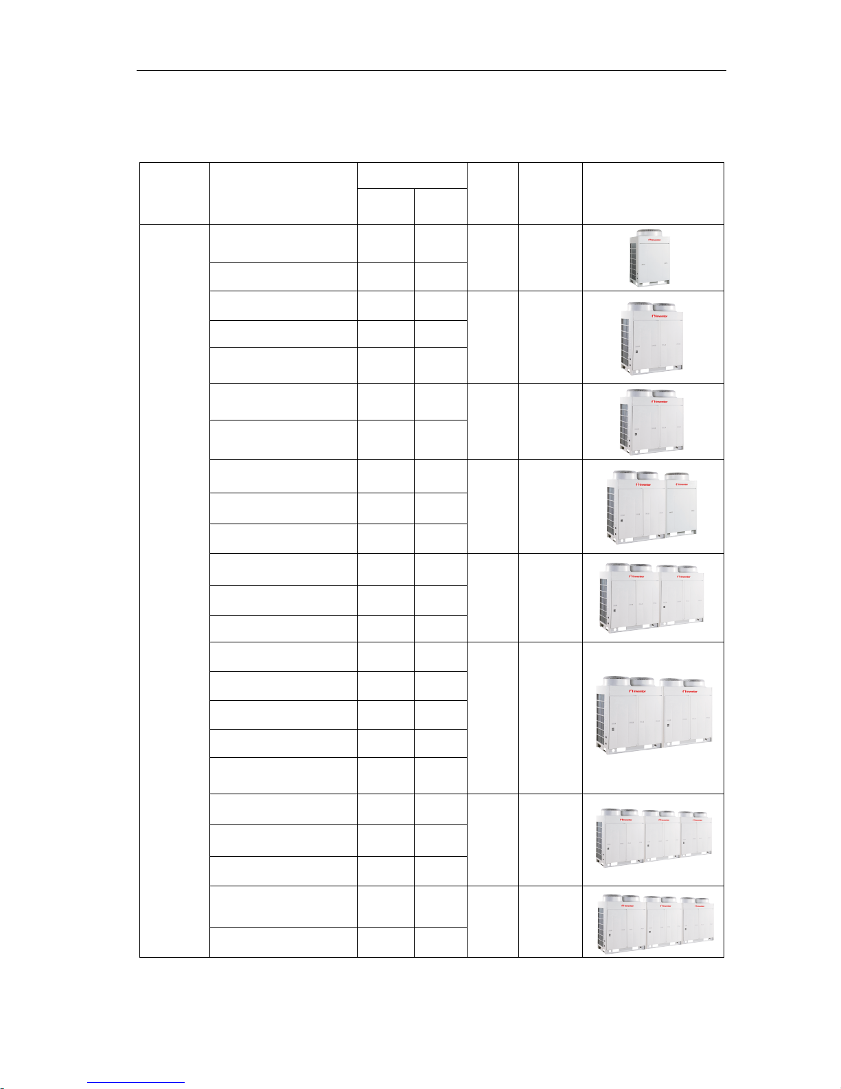
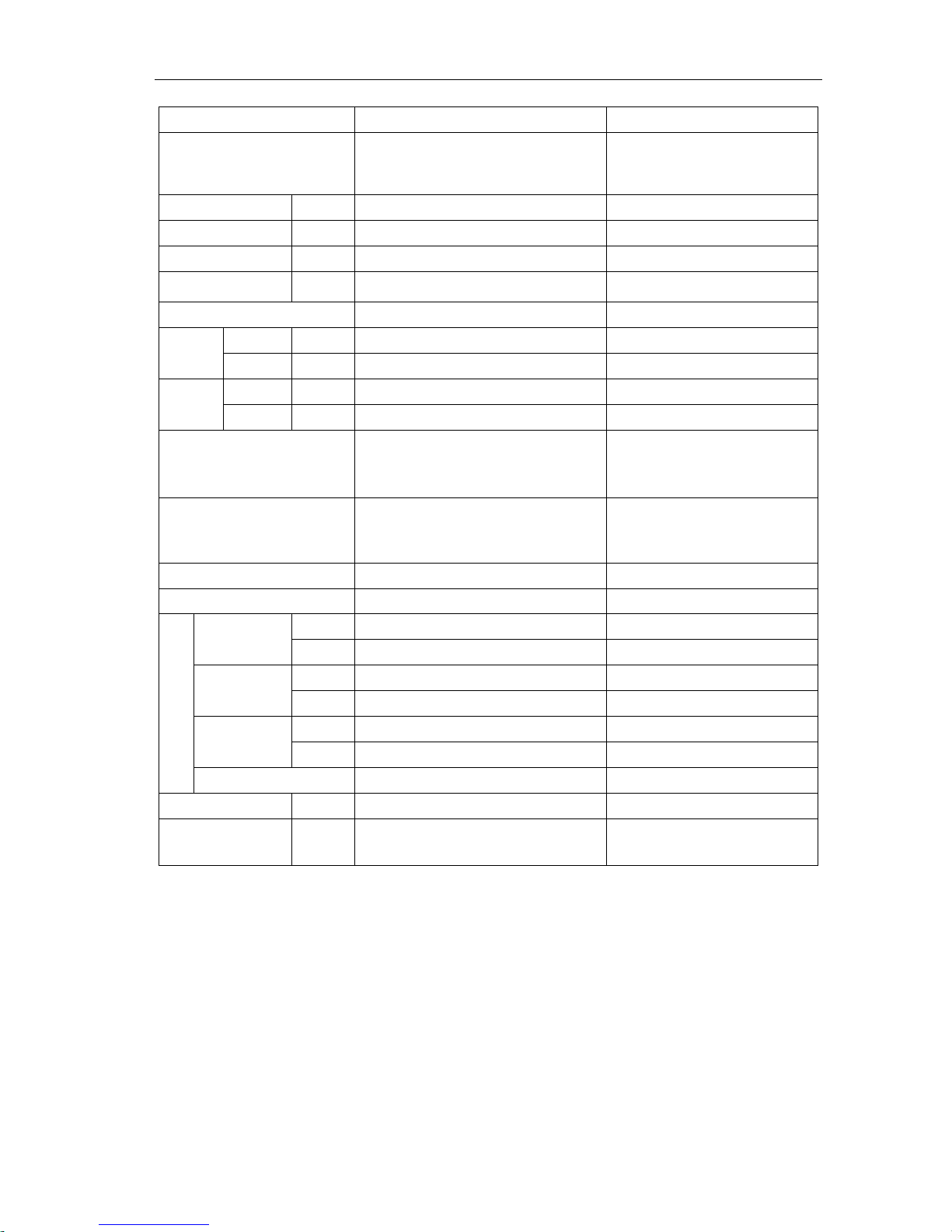
1 MODELS LIST
1.1 Outdoor Unit
Units Series Model
Capacity
Ref.
Power
Supply
Appearance
Cooling
(Btu/h)
Heating
(Btu/h)
MODULA
R D.C.
INVERTE
R MULTI
VRF
INV-Pdm224W/NaB-M 76429 85300
R410A
380-415V
3N~50Hz
INV-Pdm280W/NaB-M 95536 107478
INV-Pdm335W/NaB-M 114302 127950
R410A
380-415V
3N~50Hz
INV-Pdm400W/NaB-M 136480 153540
INV-Pdm450W/NaB-M 153540 170600
INV-Pdm504W/NaB-M 171965 192778
R410A
380-415V
3N~50Hz
INV-Pdm560W/NaB-M 191072 214956
INV-Pdm615W/NaB-M 209838 235428
R410A
380-415V
3N~50Hz
INV-Pdm670W/NaB-M 232016 261018
INV-Pdm730W/NaB-M 249076 278078
INV-Pdm785W2/NaB-M 267842 298550
R410A
380-415V
3N~50Hz
INV-Pdm850W2/NaB-M 290020 324140
INV-Pdm900W2/NaB-M 307080 341200
INV-Pdm950W3/NaB-M 327552 368496
R410A
380-415V
3N~50Hz
INV-Pdm1008W3/NaB-M 344612 385556
INV-Pdm1065W3/NaB-M 363378 406028
INV-Pdm1130W3/NaB-M 385556 431618
INV-Pdm1180W3/NaB-M 402616 448678
INV-Pdm1235W3/NaB-M 421382 469150
R410A
380-415V
3N~50Hz
INV-Pdm1300W3/NaB-M 443560 494740
INV-Pdm1350W3/NaB-M 460620 511800
INV-Pdm1405W4/NaB-M 481092 539096
R410A
380-415V
3N~50Hz
INV-Pdm1456W4/NaB-M 498152 556156

MODULAR D.C. INVERTER MULTI VRF PRODUCT
3
Continue
Units
Series
Model
Capacity
Ref.
Power
Supply
Appearance
Cooling
(Btu/h)
Heating
(Btu/h)
MODULA
R D.C.
INVERTE
R MULTI
VRF
INV-Pdm1512W4/NaB-M 516918 576628
R410A
380-415V
3N~50Hz
INV-Pdm1570W4/NaB-M 528860 602218
INV-Pdm1650W4/NaB-M 556156 619278
INV-Pdm1700W4/NaB-M 574922 639750
R410A
380-415V
3N~50Hz
INV-Pdm1750W4/NaB-M 597100 665340
INV-Pdm1800W4/NaB-M 614160 682400
Notes: a. Design of this unit accords with the Standard GB/T 18837-2002.
b. Cooling only unit (INVL type) has no items on heating;
c. Noise was tested in semi-silenced room, so the actual noise value will be a little higher for change of ambient.
d. The charge amount of R410A in the list is only the sealed amount when outdoor unit outgoing. When installing,
calculate the additional charge amount according to actual length of pipe and the matched indoor units;
e. Nominal capacities are based on the following conditions.
Cooling Heating
Indoor :27℃
(80.6
℉)/19
℃
(66.2
℉
)
Outdoor: 35℃(95℉ )/-
Indoor: 20℃ (68℉)/-
Outdoor : 7℃(44.6℉ )/6℃(42.8℉);
MODULAR D.C. INVERTER MULTI VRF PRODUCT
4
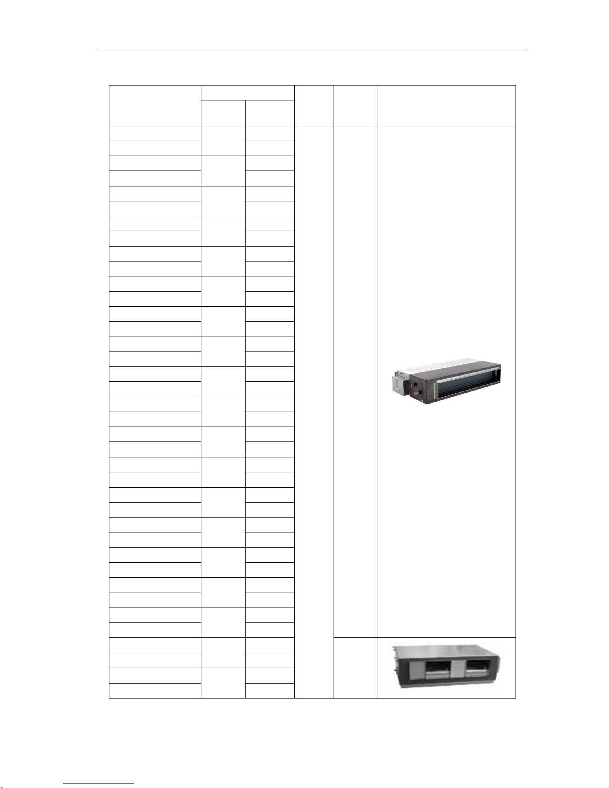
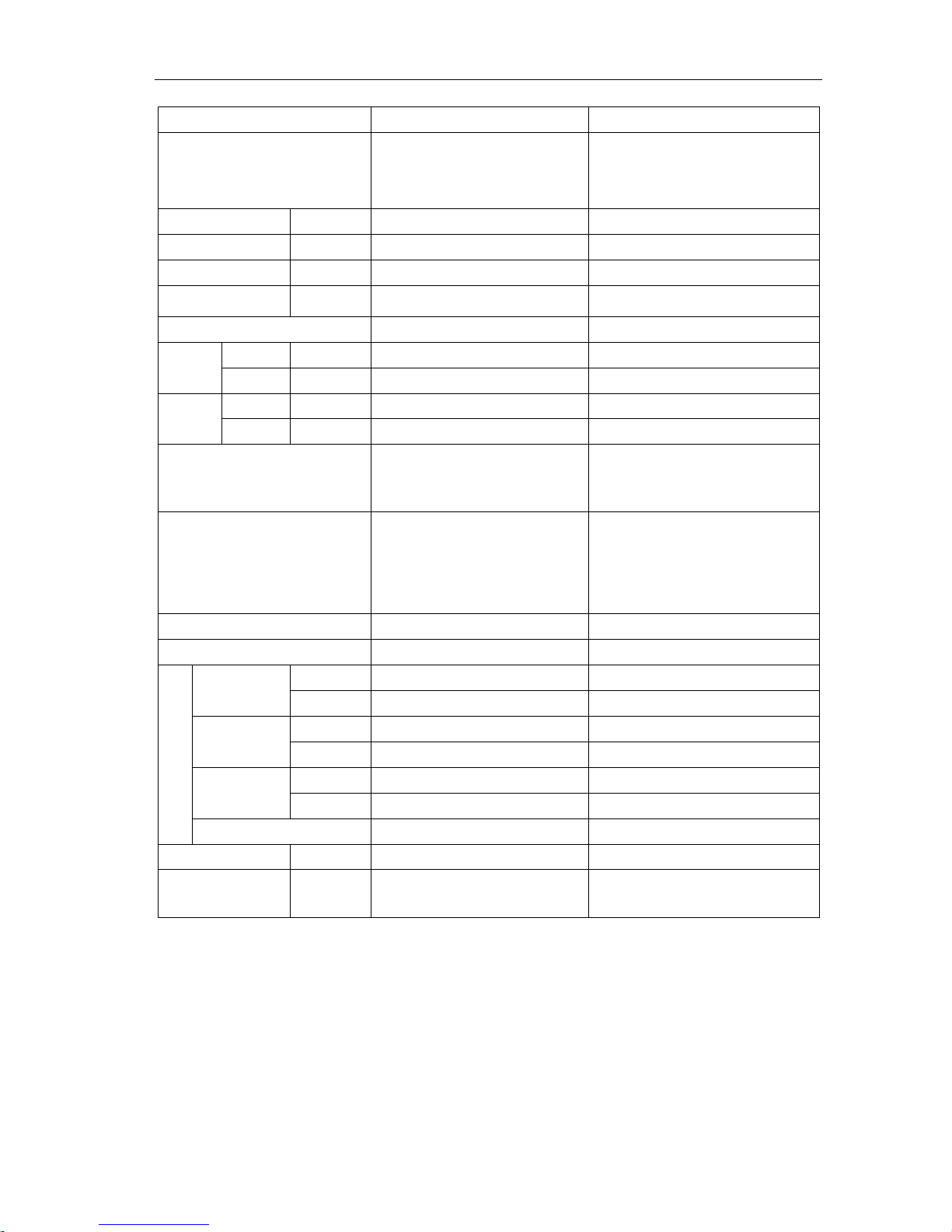
1.2 Indoor Unit
1.2.1 Duct type
Model
Capacity
Ref
Power
Supply
Appearance
Cooling
(Btu/h)
Heating
(Btu/h)
INV-R22P/Na-K
7507
8530
R410A
220V
50Hz
INVL-R22P/Na-K
/
INV-R25P/Na-K
8530
10236
INVL-R25P/Na-K
/
INV-R28P/Na-K
9554
10918
INVL-R28P/Na-K
/
INV-R32P/Na-K
10919
12283
INVL-R32P/Na-K
/
INV-R36P/Na-K
12284
13648
INVL-R36P/Na-K
/
INV-R40P/Na-K
13649
15354
INVL-R40P/Na-K
/
INV-R45P/Na-K
15355
17060
INVL-R45P/Na-K
/
INV-R50P/Na-K
17061
19790
INVL-R50P/Na-K
/
INV-R56P/Na-K
19108
21496
INVL-R56P/Na-K
/
INV-R63P/Na-K
21496
23884
INVL-R63P/Na-K
/
INV-R71P/Na-K
24226
27296
INVL-R71P/Na-K
/
INV-R80P/Na-K
27297
30026
INVL-R80P/Na-K
/
INV-R90P/Na-K
30709
34120
INVL-R90P/Na-K
/
INV-R100P/Na-K
34121
37532
INVL-R100P/Na-K
/
INV-R112P/Na-K
38216
42650
INVL-R112P/Na-K
/
INV-R125P/Na-K
42652
46060
INVL-R125P/Na-K
/
INV-R140P/Na-K
47770
51180
INVL-R140P/Na-K
/
INV-R224P/Na-M
76432
85304
380V
50Hz
INVL-R224P/Na-M
/
INV-R280P/Na-M
95540
105780
INVL-R280P/Na-M
/
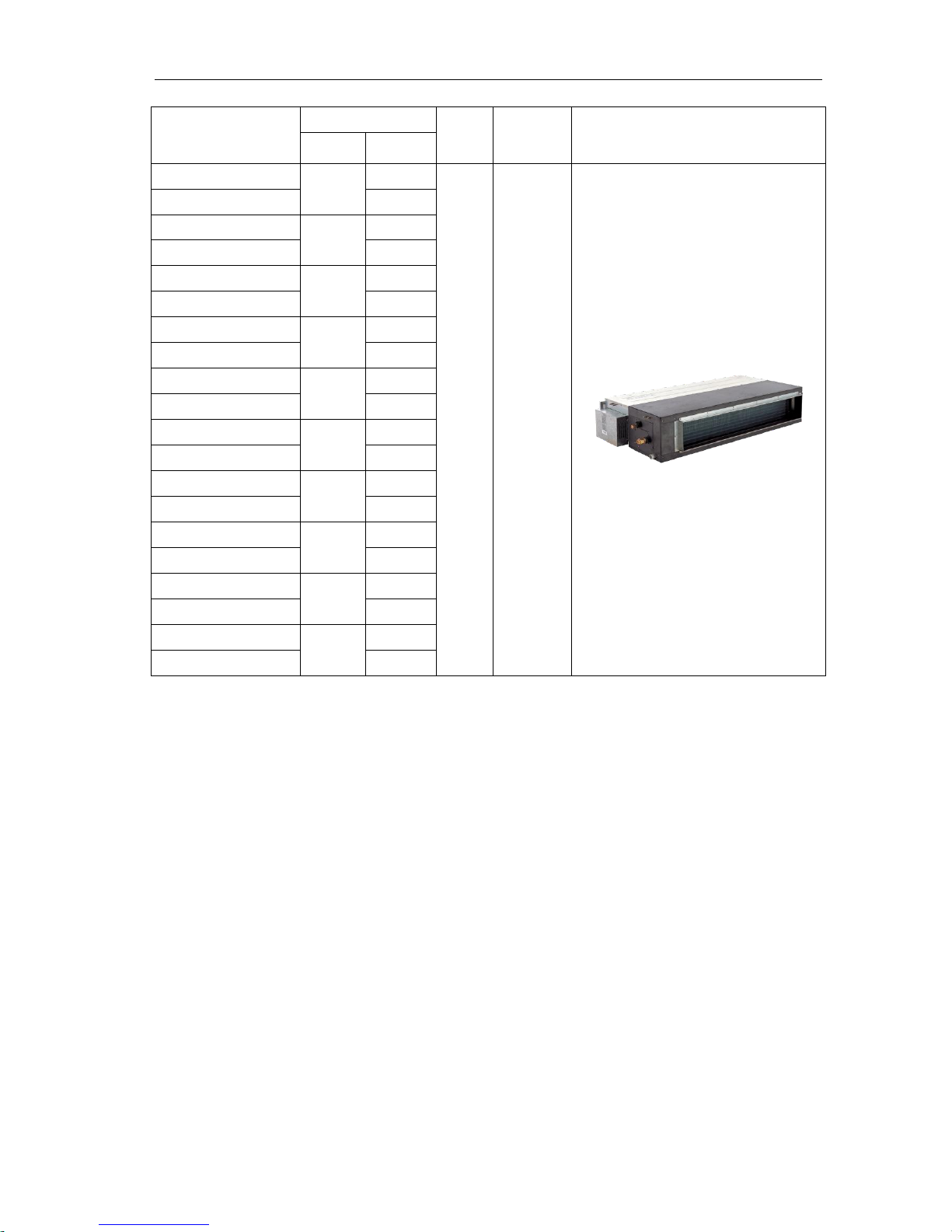
MODULAR D.C. INVERTER MULTI VRF PRODUCT
5
Model
Capacity
Ref
Power
Supply
Appearance
Cooling
(Btu/h)
Heating
(Btu/h)
INV-R22P/NaB-K
7507
8530
R410A
220V
50Hz
INVL-R22P/NaB-K
/
INV-R25P/NaB-K
8530
10236
INVL-R25P/NaB-K
/
INV-R28P/NaB-K
9554
10918
INVL-R28P/NaB-K
/
INV-R36P/NaB-K
12284
13648
INVL-R36P/NaB-K
/
INV-R45P/NaB-K
15355
17060
INVL-R45P/NaB-K
/
INV-R56P/NaB-K
19108
21496
INVL-R56P/NaB-K
/
INV-R71P/NaB-K
24226
27296
INVL-R71P/NaB-K
/
INV-R90P/NaB-K
30709
34120
INVL-R90P/NaB-K
/
INV-R112P/NaB-K
38216
42650
INVL-R112P/NaB-K
/
INV-R140P/NaB-K
47770
51180
INVL-R140P/NaB-K
/
MODULAR D.C. INVERTER MULTI VRF PRODUCT
6
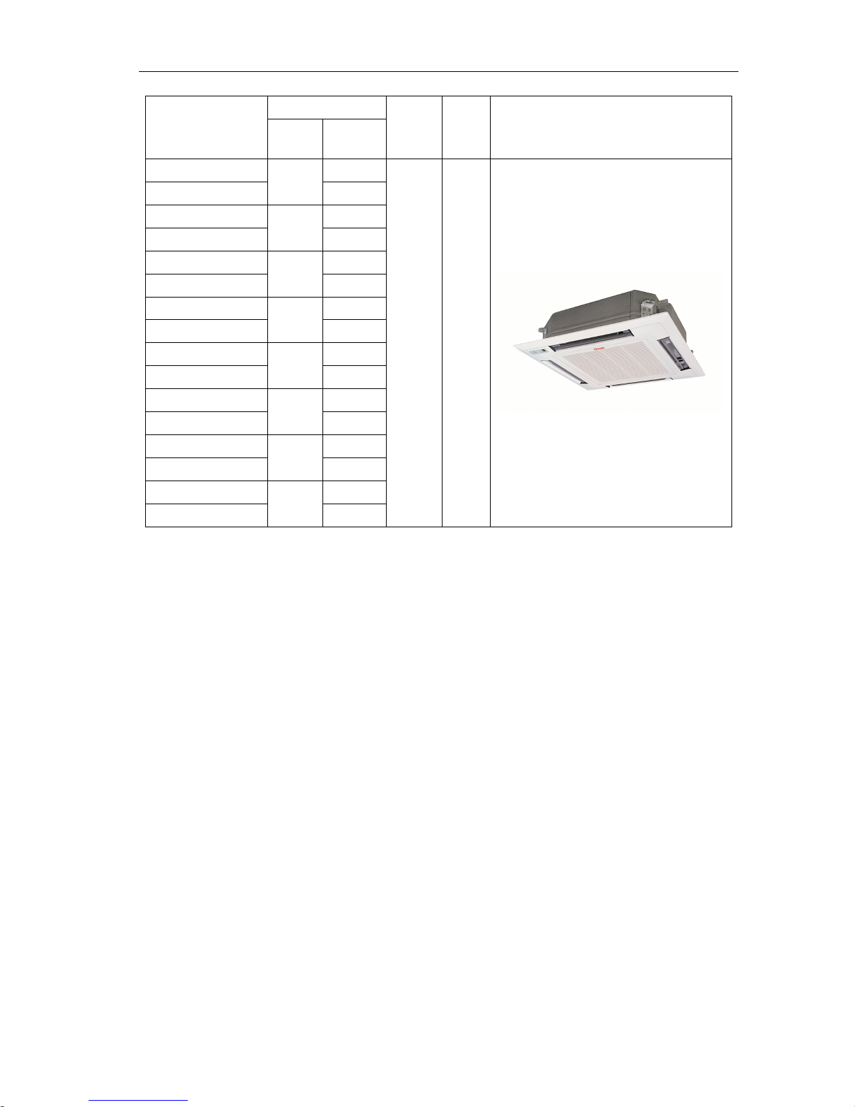
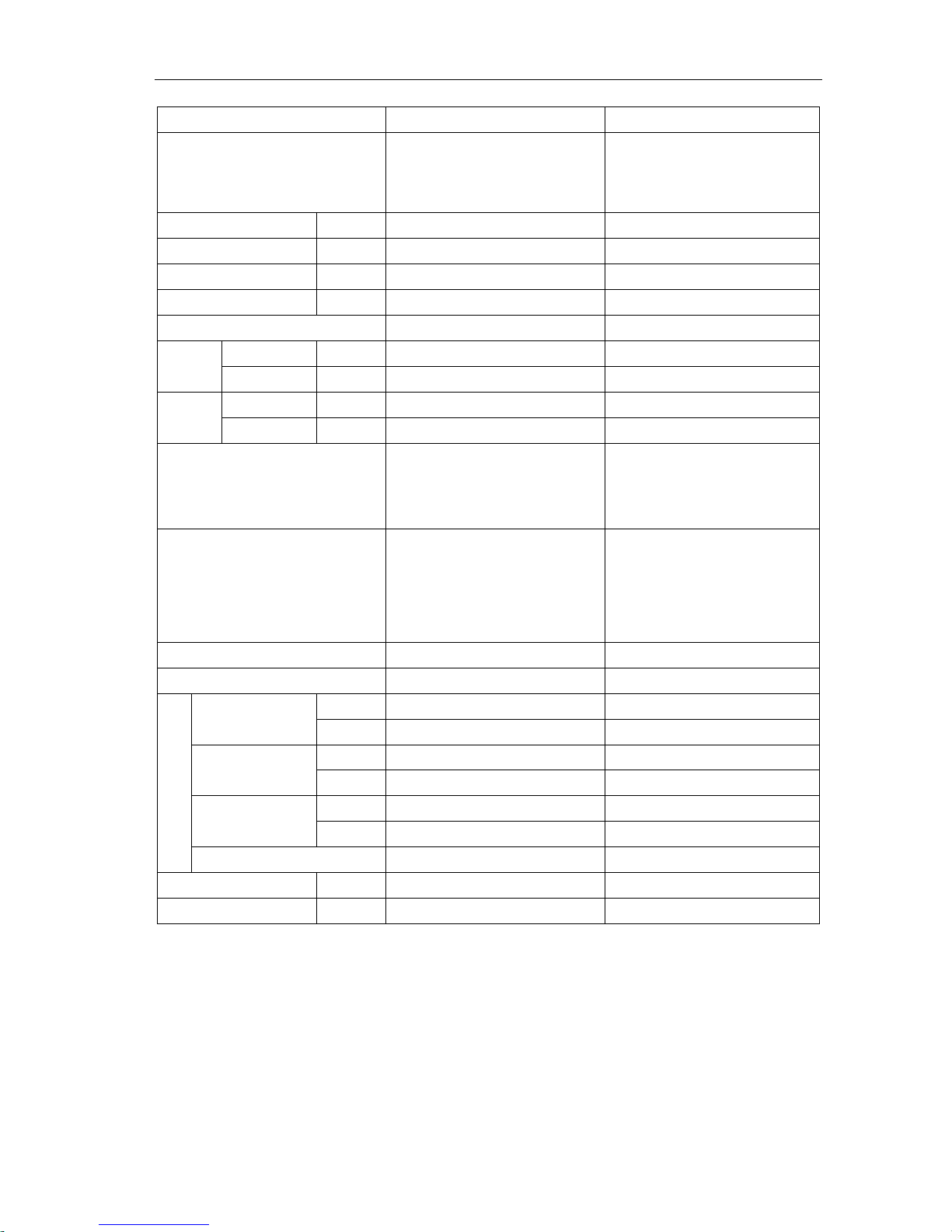
1.2.2 Cassette type
Model
Capacity
Ref
Power
Supply
Appearance
Cooling
(Btu/h)
Heating
(Btu/h)
INV-R28T/Na-K
9550
10900
R410A
220V
50Hz
INVL-R28T/Na-K /
INV-R36T/Na-K
12280
13650
INVL-R36T/Na-K /
INV-R45T/Na-K
15360
17060
INVL-R45T/Na-K /
INV-R50T/Na-K
17060
19790
INVL-R50T/Na-K /
INV-R56T/Na-K
19100
21500
INVL-R56T/Na-K /
INV-R71T/Na-K
24230
27300
INVL-R71T/Na-K /
INV-R90T/Na-K
30700
34120
INVL-R90T/Na-K /
INV-R112T/Na-K
38210
42650
INVL-R112T/Na-K /
MODULAR D.C. INVERTER MULTI VRF PRODUCT
7
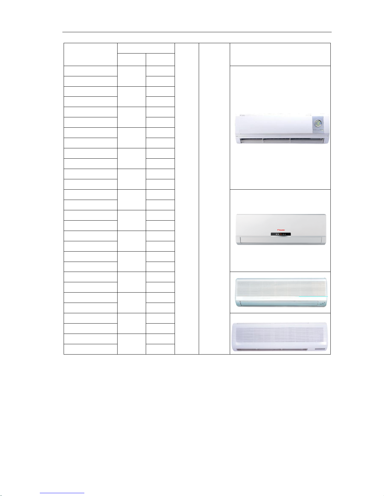
1.2.3 Wall mounted type
Model
Capacity
Ref
Power
Supply
Appearance
Cooling
(Btu/h)
Heating
(Btu/h)
INV-R22G/NaB-K
7507
8530
INVL-R22G/NaB-K /
INV-R28G/NaB-K
9554
10919
INVL-R28G/NaB-K /
INV-R36G/NaB-K
12284
13649
INVL-R36G/NaB-K /
INV-R45G/NaB-K
15355
17061
INVL-R45G/NaB-K /
INV-R50G/NaB-K
17061
19790
INVL-R50G/NaB-K /
INV-R56G/NaB-K
19108
21496
INVL-R56G/NaB-K /
INV-R22G/NaC-K
7507
8530
INVL-R22G/NaC-K /
INV-R28G/NaC-K
9554
10919
INVL-R28G/NaC-K /
INV-R36G/NaC-K
12284
13649
INVL-R36G/NaC-K /
INV-R45G/NaC-K
15355
17061
INVL-R45G/NaC-K /
INV-R50G/Na-K
17061
19790
INVL-R50G/Na-K /
INV-R56G/Na-K
19108
21496
INVL-R56G/Na-K /
INV-R71G/Na-K
24226
27297
INVL-R71G/Na-K /
INV-R80G/Na-K
27297
30709
INVL-R80G/Na-K /

MODULAR D.C. INVERTER MULTI VRF PRODUCT
8
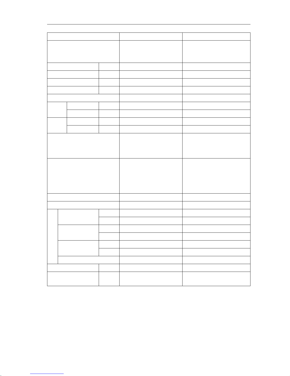
1.2.4 Floor ceiling type
Model
Capacity
Ref
Power
Supply
Appearance
Cooling
(Btu/h)
Heating
(Btu/h)
INV-R28Zd/Na-K
9554
10919
R410A
220V
50Hz
INVL-R28Zd/Na-K /
INV-R36Zd/Na-K
12284
13649
INVL-R36Zd/Na-K /
INV-R50Zd/Na-K
17061
19790
INVL-R50Zd/Na-K /
INV-R71Zd/Na-K
24226
27297
INVL-R71Zd/Na-K /
INV-R90Zd/Na-K
30709
34121
INVL-R90Zd/Na-K /
INV-R112Zd/Na-K
38216
42652
INVL-R112Zd/Na-K /
INV-R125Zd/Na-K
42652
46064
INVL-R125Zd/Na-K /
Note:1Ton =12000Btu/h = 3.517kW
Notes: a. Design of this unit accords with the Standard GB/T 18837-2002.
b. Cooling only unit (INVL type) has no items on heating;
c. Noise was tested in semi-silenced room, so the actual noise value will be a little higher for change of ambient.
d. Nominal capacities are based on the following conditions.
Cooling Heating
Indoor :27℃(80.6℉)/19℃(66.2℉)
Outdoor: 35℃(95℉)/-
Indoor: 20℃(68℉)/-
Outdoor : 7℃(44.6℉)/6℃(42.8℉)
MODULAR D.C. INVERTER MULTI VRF PRODUCT
9
2 NOMENCLATURE
2.1 Nomenclature of Outdoor Unit
INV □ L - Pdm
224 W /
Na
B - M 1 2 3 4 5 6 7 8 9
NO.
Description
Options
1
INV
INVENTOR Multi Variable
2
Code for weather
Default:T1 T2:T2 weather T3:T3 weather
3
Modular Digital
L: Cooling Only
Default: Heat pump
4
Units Series
Pdm: MODULAR DC inverter VRF
5
Nominal cooling capacity
224 represents 22.4kW
Btu/h=kW×3412
6
W
Outdoor unit
7
Refrigerant
Na: R410A
8
Sequences
B: The second generation
9
Power complement
M: 380V, 3N~, 50 Hz
2.2 Nomenclature of Indoor Unit
INV
□
L - R
36 P /
Na
B - K
1 2 3 4 5 6 7 8
9
NO.
Description
Options
1
INV
INVENTOR Multi Variable
2
Code for weather
Default:T1 T2:T2 weather T3:T3 weather
3
Code for model
L: Cooling Only
Default: Heat pump
4
Code for function
R: R-R series
5
Nominal cooling capacity
36 represents 3.6kW
Btu/h=kW×3412
6
Code for unit type
P=Duct type
T=Cassette type
G=Wall mounted
Zd=Floor ceiling
7
Refrigerant
Na: R410A
8
Sequences
B: The second generation
9
Power supply
K: 220-240V 50Hz
Example: INV-R22G/NaB-K. A wall mounted indoor unit of INVENTOR, and the nominal cooling capacity is 2.2kw. It's the
second generation product, and It could connect the outdoor unit with digital scroll, the power supply is 220V-240V, 50Hz.
MODULAR D.C. INVERTER MULTI VRF PRODUCT
10
3 FUNCTION
For
Comfortable
Air Conditioning
Auto Restart
Fan Operation Mode
LCD Remote Controller (Option)
Auto Swing Function
Ceiling Soiling Prevention
Program Dry
High Fan Speed Mode
High Ceiling Application
Two Select Thermo Sensor
Hot Start
Timer Selector
For Easy
Construction and
Maintenance
Fresh Air Intake Directly from The Unit
Drain Pump
Long Life Filter
Ultra-Long life Filter (Option)
Mold Resistant Treatment for Filter
Filter Sign
Mold Resistant Drain Pan
Emergency Operation
Self Diagnoses Function
For Flexible
Control
Set Back Time Clock
Double Remote Control
Group Control By 1 Remote Controller
Control By External Command
Remote/Centralized Control
MODULAR D.C. INVERTER MULTI VRF PRODUCT
11
4 PRODUCT DATA
4.1 Product data of outdoor
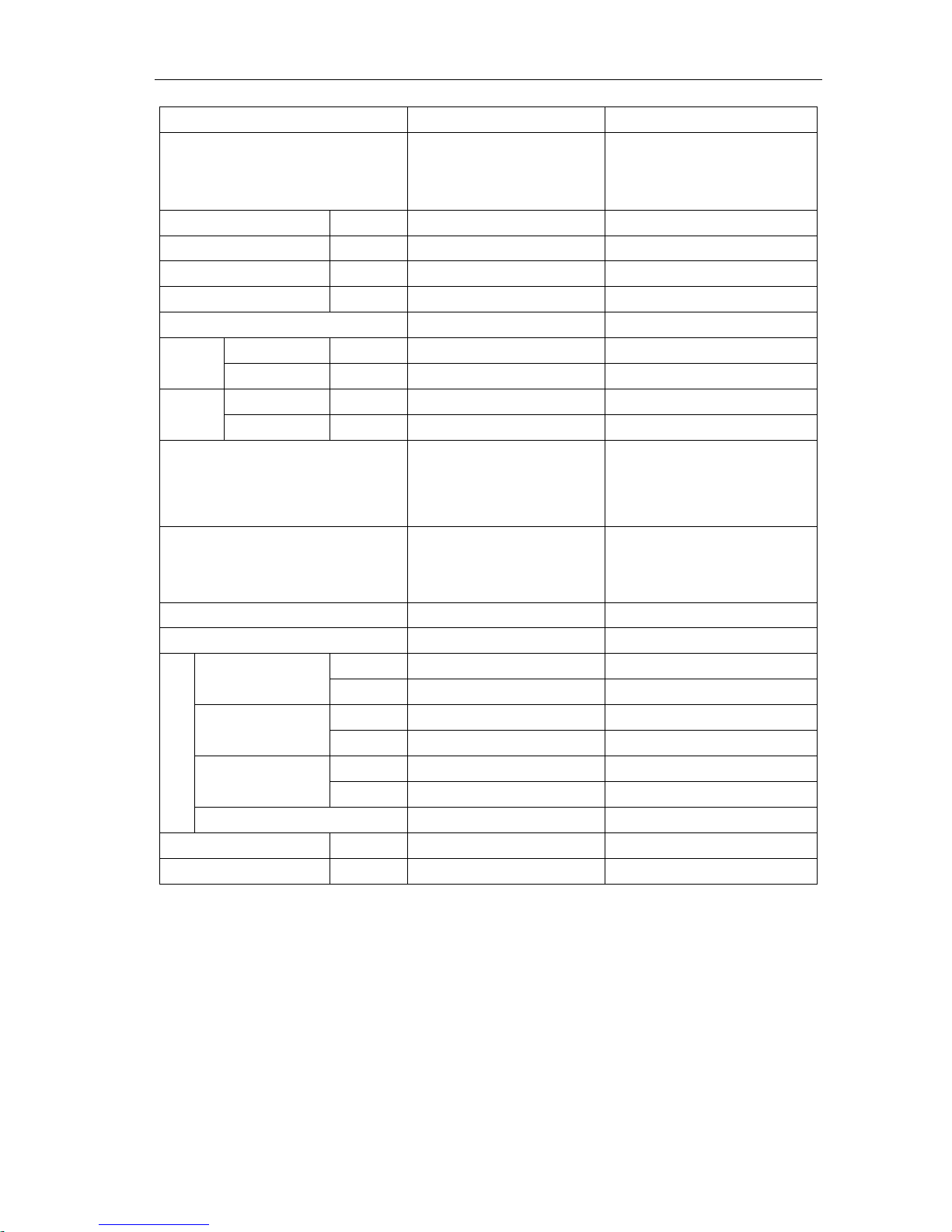
Model
INV-Pdm224W/NaB-M
INV-Pdm280W/NaB-M
Cooling capacity
kW
22.4
28.0
Heating capacity
kW
25.0
31.5
Sound Pressure Level
dB(A)
58
58
R410A charge amount
kg
12
13
Power Supply
380-415V 3N~50Hz
380-415V 3N~50Hz
Rated
power
Cooling
kW
5.52
7.52
Heating
kW
5.82
7.70
Rated
current
Cooling
A
9.87
13.44
Heating
A
10.40
13.76
IPLV
4.15
3.95
Dimension (mm)
(W×D×H)
930×770×1670
930×770×1670
Compressor
(D.C.Inverter Scroll type compressor
+constant speed scroll compressor )
(D.C.Inverter Scroll type compressor
+constant speed scroll compressor)
Water proof level
IP24
IP24
Climate type
T1
T1
Connection pipe
Gas pipe
mm
Φ22.2
Φ22.2
Inch
7/8
7/8
Liquid pipe
mm
Φ9.52
Φ9.52
Inch
3/8
3/8
Connecting mode
Brazing Connection
Brazing Connection
Net weight
kg
255
255
Recommended power
cord
mm2×pc
6.0×5
6.0×5
Note:
a. The data will change with the change of products. Refer to those parameters listed on nameplate.
b. Noise was tested in semi-silenced room, so the actual noise value will be a litter higher for change of ambient.
c. The charge amount of refrigerant in the list is the datum when there is not drop height vertically between indoor unit and
outdoor unit, without consideration of connection pipe. So calculate the additional charge amount according to actual
condition during installation.
d. Section area of lead wire is only applicable for 15-m distance.If above, increase the section area to avoid overload of
current which would cause burnout of lead wire.
e. The outdoor fan of this unit is without static pressure.If static pressure is required, please specially notice it on purchase
order.
f. Running condition of cooling : outdoor tem -5℃~48℃; running condition of heating: outdoor tem-20℃~27℃.
MODULAR D.C. INVERTER MULTI VRF PRODUCT
12
Model
INV-Pdm335W/NaB-M
INV-Pdm400W/NaB-M
Cooling capacity
kW
33.5
40.0
Heating capacity
kW
37.5
45.0
Sound Pressure Level
dB(A)
60
61
R410A charge amount
kg
15
16
Power Supply
380-415V 3N~50Hz
380-415V 3N~50Hz
Rated
power
Cooling
kW
9.23
12.45
Heating
kW
9.38
11.2
Rated
current
Cooling
A
16.50
22.25
Heating
A
16.77
20.02
IPLV
4.15
3.95
Dimension (mm)
(W×D×H)
1340×770×1670
1340×770×1670
Compressor
(D.C.Inverter Scroll type compressor
+constant speed scroll compressor×2)
(D.C.Inverter Scroll type compressor
+constant speed scroll compressor×2)
Water proof level
IP24
IP24
Climate type
T1
T1
Connection pipe
Gas pipe
mm
Φ28.6
Φ28.6
Inch
9/8
9/8
Liquid pipe
mm
Φ12.7
Φ12.7
Inch
1/2
1/2
Connecting mode
Brazing Connectio
Brazing Connection
Net weight
kg
350
350
Recommended power
cord
mm
2
×p
c
10.0×5
10.0×5
Note:
a. The data will change with the change of products. Refer to those parameters listed on nameplate.
b. Noise was tested in semi-silenced room, so the actual noise value will be a litter higher for change of ambient.
c. The charge amount of refrigerant in the list is the datum when there is not drop height vertically between indoor unit and
outdoor unit, without consideration of connection pipe. So calculate the additional charge amount according to actual
condition during installation.
d. Section area of lead wire is only applicable for 15-m distance.If above, increase the section area to avoid overload of
current which would cause burnout of lead wire.
e. The outdoor fan of this unit is without static pressure.If static pressure is required, please specially notice it on purchase
order.
f. Running condition of cooling : outdoor tem -5℃~48℃; running condition of heating: outdoor tem-20℃~27℃.

MODULAR D.C. INVERTER MULTI VRF PRODUCT
13
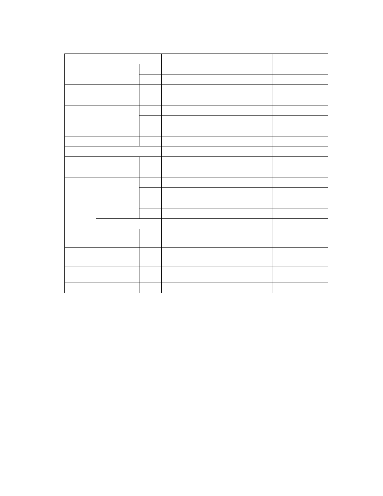
Model(Combined unit)
INV-Pdm450W/NaB-M
INV-Pdm504W/NaB-M
Model(Single unit)
INV-Pdm224W/NaB-M
+INV-Pdm280W/NaB-M
Cooling capacity
kW
45.0
50.4
Heating capacity
kW
50.0
56.5
Sound Pressure Level
dB(A)
61
62
R410A charge amount
kg
17
12+13
Power Supply
380-415V 3N~50Hz
380-415V 3N~50Hz
Rated power
Cooling
kW
14.32
5.52+7.52
Heating
kW
13.90
5.82+7.70
Rated current
Cooling A 25.60
9.87+13.44
Heating A 24.85
10.40+13.76
IPLV
4.15
-
Dimension (mm)
(W×D×H)
(1340×770×1670)
(930×770×1670)
+(930×770×1670)
Compressor
(D.C.Inverter Scroll type
compressor +constant speed scroll
compressor×2)
(D.C.Inverter Scroll type
compressor +constant speed scroll
compressor)×2
Water proof level
IP24
IP24
Climate type
T1
T1
Connection pipe
Gas pipe
mm
Φ28.6
Φ28.6
Inch
9/8
9/8
Liquid pipe
mm
Φ12.7
Φ15.9
Inch
1/2
5/8
Oil equalizing pipe
mm
-
Φ12.7
Inch
-
1/2
Connecting mode
Brazing Connectio
Brazing Connection
Net weight
kg
370
255+255
Recommended power cord
mm2×pc
10.0×5
6.0×5+6.0×5
Note:
a. The data will change with the change of products. Refer to those parameters listed on nameplate.
b. Noise was tested in semi-silenced room, so the actual noise value will be a litter higher for change of ambient.
c. The charge amount of refrigerant in the list is the datum when there is not drop height vertically between indoor unit and
outdoor unit, without consideration of connection pipe. So calculate the additional charge amount according to actual
condition during installation.
d. Section area of lead wire is only applicable for 15-m distance.If above, increase the section area to avoid overload of
current which would cause burnout of lead wire.
e. The outdoor fan of this unit is without static pressure.If static pressure is required, please specially notice it on purchase
order.
f. Running condition of cooling : outdoor tem -5℃~48℃; running condition of heating: outdoor tem-20℃~27℃.
MODULAR D.C. INVERTER MULTI VRF PRODUCT
14
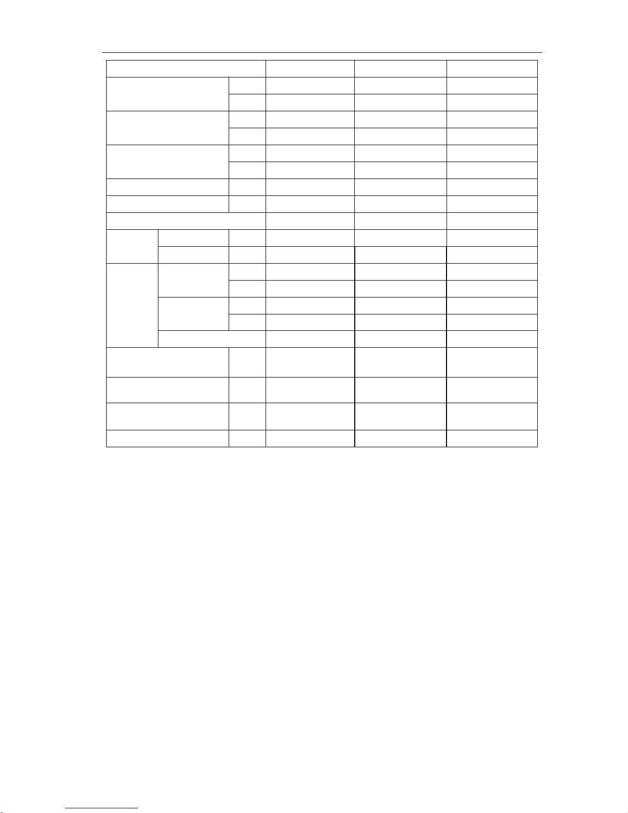
Model (Combined unit)
INV-Pdm560W2/NaB-M
INV-Pdm615W2/NaB-M
Model(Single unit)
INV-Pdm280W/NaB-M
+ INV-Pdm280W/NaB-M
INV-Pdm280W/NaB-M
+ INV-Pdm335W/NaB-M
Cooling capacity
kW
56.0
61.5
Heating capacity
kW
63.0
69.0
Sound Pressure Level
dB(A)
62
62
R410A charge
amount
kg
13+13
13+15
Power Supply
380-415V 3N~50Hz
380-415V 3N~50Hz
Rated
power
Cooling
kW
7.52+7.52
7.52+9.23
Heating
kW
7.70+7.70
7.70+9.38
Rated
current
Cooling A 13.44+13.44
13.44+16.50
Heating A 13.76+13.76
13.76+16.77
Dimension (mm)
(W×D×H)
(930×770×1670)
+(930×770×1670)
(930×770×1670)
+(1340×770×1670)
Compressor
(D.C.Inverter Scroll type
compressor +constant speed scroll
compressor)×2
(D.C.Inverter Scroll type compressor
+constant speed scroll compressor)+
(D.C.Inverter Scroll type compressor
+constant speed scroll compressor×2)
Water proof level
IP24
IP24
Climate type
T1
T1
Connection pipe
Gas pipe
mm
Φ28.6
Φ28.6
Inch
9/8
9/8
Liquid pipe
mm
Φ15.9
Φ15.9
Inch
5/8
5/8
Oil equalizing
pipe
mm
Φ12.7
Φ12.7
Inch
1/2
1/2
Connecting mode
Brazing Connectio
Brazing Connection
Net weight
kg
255+255
255+350
Recommended power
cord
mm2×pc
6.0×5+6.0×5
6.0×5+10.0×5
Note:
a. The data will change with the change of products. Refer to those parameters listed on nameplate.
b. Noise was tested in semi-silenced room, so the actual noise value will be a litter higher for change of ambient.
c. The charge amount of refrigerant in the list is the datum when there is not drop height vertically between indoor unit and
outdoor unit, without consideration of connection pipe. So calculate the additional charge amount according to actual
condition during installation.
d. Section area of lead wire is only applicable for 15-m distance.If above, increase the section area to avoid overload of
current which would cause burnout of lead wire.
e. The outdoor fan of this unit is without static pressure.If static pressure is required, please specially notice it on purchase
order.
f. Running condition of cooling : outdoor tem -5℃~48℃; running condition of heating: outdoor tem-20℃~27℃.
MODULAR D.C. INVERTER MULTI VRF PRODUCT
15
Model (Combined unit)
INV-Pdm670W2/NaB-M
INV-Pdm730W2/NaB-M
Model(Single unit)
INV-Pdm280W/NaB-M
+ INV-Pdm400W/NaB-M
INV-Pdm280W/NaB-M
+ INV-Pdm450W/NaB-M
Cooling capacity
kW
68.0
73.0
Heating capacity
kW
76.5
81.5
Sound Pressure
Level
dB(A)
62
63
R410A charge
amount
kg
13+16
13+17
Power Supply
380-415V 3N~50Hz
380-415V 3N~50Hz
Rated
power
Cooling
kW
7.52+12.45
7.52+14.32
Heating
kW
7.70+11.2
7.70+13.90
Rated
current
Cooling A 13.44+22.25
13.44+25.60
Heating A 13.76+20.02
13.76+24.85
Dimension (mm)
(W×D×H)
(930×770×1670)
+(1340×770×1670)
(930×770×1670)
+(1340×770×1670)
Compressor
(D.C.Inverter Scroll type compressor
+constant speed scroll compressor×1)+
(D.C.Inverter Scroll type compressor
+constant speed scroll compressor×2)
(D.C.Inverter Scroll type
compressor +constant speed scroll
compressor×1)+(D.C.Inverter
Scroll type compressor +constant
speed scroll compressor×2)
Water proof level
IP24
IP24
Climate type
T1
T1
Connection pipe
Gas pipe
mm
Φ34.9
Φ34.9
Inch
11/8
11/8
Liquid pipe
mm
Φ15.9
Φ19.05
Inch
5/8
3/4
Oil equalizing
pipe
mm
Φ12.7
Φ12.7
Inch
1/2
1/2
Connecting mode
Brazing Connectio
Brazing Connection
Net weight
kg
255+350
255+370
Recommended
power cord
mm2×pc
6.0×5+10.0×5
6.0×5+10.0×5
Note:
a. The data will change with the change of products. Refer to those parameters listed on nameplate.
b. Noise was tested in semi-silenced room, so the actual noise value will be a litter higher for change of ambient.
c. The charge amount of refrigerant in the list is the datum when there is not drop height vertically between indoor unit and
outdoor unit, without consideration of connection pipe. So calculate the additional charge amount according to actual
condition during installation.
d. Section area of lead wire is only applicable for 15-m distance.If above, increase the section area to avoid overload of
current which would cause burnout of lead wire.
e. The outdoor fan of this unit is without static pressure.If static pressure is required, please specially notice it on purchase
order.
f. Running condition of cooling : outdoor tem -5℃~48℃; running condition of heating: outdoor tem-20℃~27℃.
MODULAR D.C. INVERTER MULTI VRF PRODUCT
16
Model (Combined unit)
INV-Pdm785W2/NaB-M
INV-Pdm850W2/NaB-M
Model(Single unit)
INV-Pdm335W/NaB-M
+ INV-Pdm450W/NaB-M
INV-Pdm400W/NaB-M
+ INV-Pdm450W/NaB-M
Cooling capacity
kW
78.5
85.0
Heating capacity
kW
87.5
95.0
Sound Pressure Level
dB(A)
63
63
R410A charge
amount
kg
15+16
16+17
Power Supply
380-415V 3N~50Hz
380-415V 3N~50Hz
Rated
power
Cooling
kW
9.23+14.32
12.45+14.32
Heating
kW
9.38+13.90
11.2+13.90
Rated
current
Cooling A 16.50+25.60
22.25+25.60
Heating A 16.77+24.85
20.02+24.85
Dimension (mm)
(W×D×H)
(1340×770×1670)+
(1340×770×1670)
(1340×770×1670)+
(1340×770×1670)
Compressor
(D.C.Inverter Scroll type compressor
+constant speed scroll compressor×2)
×2
(D.C.Inverter Scroll type compressor
+constant speed scroll compressor×2)
×2
Water proof level
IP24
IP24
Climate type
T1
T1
Connection pipe
Gas pipe
mm
Φ34.9
Φ34.9
Inch
11/8
11/8
Liquid pipe
mm
Φ19.05
Φ19.05
Inch
3/4
3/4
Oil equalizing
pipe
mm
Φ12.7
Φ12.7
Inch
1/2
1/2
Connecting mode
Brazing Connectio
Brazing Connection
Net weight
kg
350+370
350+370
Recommended power
cord
mm2×pc
10.0×5+10.0×5
10.0×5+10.0×5
Note:
a. The data will change with the change of products. Refer to those parameters listed on nameplate.
b. Noise was tested in semi-silenced room, so the actual noise value will be a litter higher for change of ambient.
c. The charge amount of refrigerant in the list is the datum when there is not drop height vertically between indoor unit and
outdoor unit, without consideration of connection pipe. So calculate the additional charge amount according to actual
condition during installation.
d. Section area of lead wire is only applicable for 15-m distance.If above, increase the section area to avoid overload of
current which would cause burnout of lead wire.
e. The outdoor fan of this unit is without static pressure.If static pressure is required, please specially notice it on purchase
order.
f. Running condition of cooling : outdoor tem -5℃~48℃; running condition of heating: outdoor tem-20℃~27℃.
MODULAR D.C. INVERTER MULTI VRF PRODUCT
17
Model (Combined unit)
INV-Pdm900W2/NaB-M
INV-Pdm950W3/NaB-M
Model(Single unit)
INV-Pdm450W/NaB-M
+ INV-Pdm450W/NaB-M
INV-Pdm280W/NaB-M
+INV-Pdm280W/NaB-M
+ INV-Pdm400W/NaB-M
Cooling capacity
kW
90.0
96.0
Heating capacity
kW
100.0
108.0
Sound Pressure Level
dB(A
)
63
64
R410A charge
amount
kg
17+17
13+13+16
Power Supply
380-415V 3N~50Hz
380-415V 3N~50Hz
Rated
power
Cooling
kW
14.32+14.32
7.52+7.52+12.45
Heating
kW
13.90+13.90
7.70+7.70+11.2
Rated
current
Cooling A 25.60+25.60
13.44+13.44+22.25
Heating A 24.85+24.85
13.76+13.44+20.02
Dimension (mm)
(W×D×H)
(1340×770×1670)
+(1340×770×1670)
(930×770×1670)+(930×770×1670)
+(1340×770×1670)
Compressor
(D.C.Inverter Scroll type compressor
+constant speed scroll compressor×2)
×2
(D.C.Inverter Scroll type compressor
+constant speed scroll compressor×2)+
(D.C.Inverter Scroll type compressor
+constant speed scroll compressor)×2
Water proof level
IP24
IP24
Climate type
T1
T1
Connection pipe
Gas pipe
mm
Φ34.9
Φ34.9
Inch
11/8
11/8
Liquid pipe
mm
Φ19.05
Φ19.05
Inch
3/4
3/4
Oil equalizing
pipe
mm
Φ12.7
Φ12.7
Inch
1/2
1/2
Connecting mode
Brazing Connection
Brazing Connection
Net weight
kg
370+370
255+255+350
Recommended power
cord
mm
2
×
pc
10.0×5+10.0×5
6.0×5+6.0×5+10.0×5
Note:
a. The data will change with the change of products. Refer to those parameters listed on nameplate.
b. Noise was tested in semi-silenced room, so the actual noise value will be a litter higher for change of ambient.
c. The charge amount of refrigerant in the list is the datum when there is not drop height vertically between indoor unit and
outdoor unit, without consideration of connection pipe. So calculate the additional charge amount according to actual
condition during installation.
d. Section area of lead wire is only applicable for 15-m distance.If above, increase the section area to avoid overload of
current which would cause burnout of lead wire.
e. The outdoor fan of this unit is without static pressure.If static pressure is required, please specially notice it on purchase
order.
f. Running condition of cooling : outdoor tem -5℃~48℃; running condition of heating: outdoor tem-20℃~27℃.
MODULAR D.C. INVERTER MULTI VRF PRODUCT
18
Model (Combined unit)
INV-Pdm1008W3/NaB-M
INV-Pdm1065W3/NaB-M
Model(Single unit)
INV-Pdm280W/NaB-M
+INV-Pdm280W/NaB-M
+ INV-Pdm450W/NaB-M
INV-Pdm280W/NaB-M
+INV-Pdm335W/NaB-M
+ INV-Pdm450W/NaB-M
Cooling capacity
kW
101.0
106.5
Heating capacity
kW
113.0
119.0
Sound Pressure Level
dB(A)
64
64
R410A charge
amount
kg
13+13+17
13+15+17
Power Supply
380-415V 3N~50Hz
380-415V 3N~50Hz
Rated
power
Cooling
kW
7.52+7.52+14.32
7.52+9.23+14.32
Heating
kW
7.70+7.70+13.90
7.70+9.38+13.90
Rated
current
Cooling A 13.44+13.44+25.60
13.44+16.50+25.60
Heating A 13.76+13.76+24.85
13.76+16.77+24.85
Dimension (mm)
(W×D×H)
(930×770×1670)+(930×770×1670)
+(1340×770×1670)
(930×770×1670)+(1340×770×1670)
+(1340×770×1670)
Compressor
(D.C.Inverter Scroll type compressor
+constant speed scroll compressor×2)+
(D.C.Inverter Scroll type compressor
+constant speed scroll compressor)×2
(D.C.Inverter Scroll type compressor
+constant speed scroll compressor)+
(D.C.Inverter Scroll type compressor
+constant speed scroll compressor×2)×2
Water proof level
IP24
IP24
Climate type
T1
T1
Connection pipe
Gas pipe
mm
Φ41.3
Φ41.3
Inch
13/8
13/8
Liquid pipe
mm
Φ19.05
Φ19.05
Inch
3/4
3/4
Oil equalizing
pipe
mm
Φ12.7
Φ12.7
Inch
1/2
1/2
Connecting mode
Brazing Connection
Brazing Connection
Net weight
kg
255+255+370
255+350+370
Recommended power
cord
mm
2
×p
c
6.0×5+6.0×5+10.0×5
6.0×5+10.0×5+10.0×5
Note:
a. The data will change with the change of products. Refer to those parameters listed on nameplate.
b. Noise was tested in semi-silenced room, so the actual noise value will be a litter higher for change of ambient.
c. The charge amount of refrigerant in the list is the datum when there is not drop height vertically between indoor unit and
outdoor unit, without consideration of connection pipe. So calculate the additional charge amount according to actual
condition during installation.
d. Section area of lead wire is only applicable for 15-m distance.If above, increase the section area to avoid overload of
current which would cause burnout of lead wire.
e. The outdoor fan of this unit is without static pressure.If static pressure is required, please specially notice it on purchase
order.
f. Running condition of cooling : outdoor tem -5℃~48℃; running condition of heating: outdoor tem-20℃~27℃.
MODULAR D.C. INVERTER MULTI VRF PRODUCT
19
Model (Combined unit)
INV-Pdm1130W3/NaB-M
INV-Pdm1180W3/NaB-M
Model(Single unit)
INV-Pdm280W/NaB-M
+ INV-Pdm400W/NaB-M
+ INV-Pdm450W/NaB-M
INV-Pdm280W/NaB-M
+ INV-Pdm450W/NaB-M
+ INV-Pdm450W/NaB-M
Cooling capacity
kW
113.0
118.0
Heating capacity
kW
126.5
131.5
Sound Pressure Level
dB(A)
64
64
R410A charge amount
kg
13+16+17
13+17+17
Power Supply
380-415V 3N~50Hz
380-415V 3N~50Hz
Rated
power
Cooling
kW
7.52+12.45+14.32
7.52+14.32+14.32
Heating
kW
7.70+11.2+13.90
7.70+13.90+13.90
Rated
current
Cooling A 13.44+22.25+25.60
13.44+25.60+25.60
Heating A 13.76+20.02+24.85
13.76+24.85+24.85
Dimension (mm)
(W×D×H)
(930×770×1670)+(1340×770×1670)
+(1340×770×1670)
(930×770×1670)+
(1340×770×1670)
+(1340×770×1670)
Compressor
(D.C.Inverter Scroll type compressor
+constant speed scroll compressor)+
(D.C.Inverter Scroll type compressor
+constant speed scroll compressor×2)
×2
(D.C.Inverter Scroll type
compressor +constant speed scroll
compressor)+
(D.C.Inverter Scroll type
compressor +constant speed scroll
compressor×2)×2
Water proof level
IP24
IP24
Climate type
T1
T1
Connection pipe
Gas pipe
mm
Φ41.3
Φ41.3
Inch
13/8
13/8
Liquid pipe
mm
Φ19.05
Φ19.05
Inch
3/4
3/4
Oil equalizing pipe
mm
Φ12.7
Φ12.7
Inch
1/2
1/2
Connecting mode
Brazing Connection
Brazing Connection
Net weight
kg
255+350+370
255+370+370
Recommended power
cord
mm2×pc
6.0×5+10.0×5+10.0×5
6.0×5+10.0×5+10.0×5
Note:
a. The data will change with the change of products. Refer to those parameters listed on nameplate.
b. Noise was tested in semi-silenced room, so the actual noise value will be a litter higher for change of ambient.
c. The charge amount of refrigerant in the list is the datum when there is not drop height vertically between indoor unit and
outdoor unit, without consideration of connection pipe. So calculate the additional charge amount according to actual
condition during installation.
d. Section area of lead wire is only applicable for 15-m distance.If above, increase the section area to avoid overload of
current which would cause burnout of lead wire.
e. The outdoor fan of this unit is without static pressure.If static pressure is required, please specially notice it on purchase
order.
f. Running condition of cooling : outdoor tem -5℃~48℃; running condition of heating: outdoor tem-20℃~27℃.
MODULAR D.C. INVERTER MULTI VRF PRODUCT
20
Model (Combined unit)
INV-Pdm1235W3/NaB-M
INV-Pdm1300W3/NaB-M
Model(Single unit)
INV-Pdm335W/NaB-M
+ INV-Pdm450W/NaB-M
+ INV-Pdm450W/NaB-M
INV-Pdm400W/NaB-M
+ INV-Pdm450W/NaB-M
+ INV-Pdm450W/NaB-M
Cooling capacity
kW
123.5
130.0
Heating capacity
kW
137.5
145.0
Sound Pressure Level
dB(A)
65
65
R410A charge
amount
kg
15+17+17
16+17+17
Power Supply
380-415V 3N~50Hz
380-415V 3N~50Hz
Rated
power
Cooling
kW
9.23+14.32+14.32
12.45+14.32+14.32
Heating
kW
9.38+13.90+13.90
11.2+13.90+13.90
Rated
current
Cooling A 16.50+25.60+25.60
22.25+25.60+25.60
Heating A 16.77+24.85+24.85
20.02+24.85+24.85
Dimension (mm)
(W×D×H)
(1340×770×1670)+(1340×770×1670)
+(1340×770×1670)
(1340×770×1670)+
(1340×770×1670)
+(1340×770×1670)
Compressor
(D.C.Inverter Scroll type compressor
+constant speed scroll compressor×2)×3
(D.C.Inverter Scroll type
compressor +constant speed scroll
compressor×2)×3
Water proof level
IP24
IP24
Climate type
T1
T1
Connection pipe
Gas pipe
mm
Φ41.3
Φ41.3
Inch
13/8
13/8
Liquid pipe
mm
Φ19.05
Φ19.05
Inch
3/4
3/4
Oil equalizing
pipe
mm
Φ12.7
Φ12.7
Inch
1/2
1/2
Connecting mode
Brazing Connection
Brazing Connection
Net weight
kg
350+370+370
350+370+370
Recommended power
cord
mm2×pc
10.0×5+10.0×5+10.0×5
10.0×5+10.0×5+10.0×5
Note:
a. The data will change with the change of products. Refer to those parameters listed on nameplate.
b. Noise was tested in semi-silenced room, so the actual noise value will be a litter higher for change of ambient.
c. The charge amount of refrigerant in the list is the datum when there is not drop height vertically between indoor unit and
outdoor unit, without consideration of connection pipe. So calculate the additional charge amount according to actual
condition during installation.
d. Section area of lead wire is only applicable for 15-m distance.If above, increase the section area to avoid overload of
current which would cause burnout of lead wire.
e. The outdoor fan of this unit is without static pressure.If static pressure is required, please specially notice it on purchase
order.
f. Running condition of cooling : outdoor tem -5℃~48℃; running condition of heating: outdoor tem-20℃~27℃.
MODULAR D.C. INVERTER MULTI VRF PRODUCT
21
Model (Combined unit)
INV-Pdm1350W3/NaB-M
INV-Pdm1405W4/NaB-M
Model(Single unit)
INV-Pdm450W/NaB-M
+ INV-Pdm450W/NaB-M
+ INV-Pdm450W/NaB-M
INV-Pdm280W/NaB-M
+ INV-Pdm280W/NaB-M
+ INV-Pdm400W/NaB-M
+ INV-Pdm450W/NaB-M
Cooling capacity
kW
135.0
141.0
Heating capacity
kW
150.0
158.0
Sound Pressure Level
dB(A)
65
65
R410A charge
amount
kg
17+17+17
13+13+16+17
Power Supply
380-415V 3N~50Hz
380-415V 3N~50Hz
Rated
power
Cooling
kW
14.32+14.32+14.32
7.52+7.52+12.45+14.32
Heating
kW
13.90+13.90+13.90
7.70+7.70+11.2+13.90
Rated
current
Cooling A 25.60+25.60+25.60
13.44+13.44+22.25+25.60
Heating A 24.85+24.85+24.85
13.76+13.76+20.02+24.85
Dimension (mm)
(W×D×H)
(1340×770×1670)+
(1340×770×1670)
+(1340×770×1670)
(930×770×1670)+(930×770×1670)
+(1340×770×1670)+
(1340×770×1670)
Compressor
(D.C.Inverter Scroll type
compressor +constant speed scroll
compressor×2)×3
(D.C.Inverter Scroll type compressor
+constant speed scroll compressor)×2+
(D.C.Inverter Scroll type compressor
+constant speed scroll compressor×2)
×2
Water proof level
IP24
IP24
Climate type
T1
T1
Connection pipe
Gas pipe
mm
Φ41.3
Φ44.5
Inch
13/8
7/4
Liquid pipe
mm
Φ19.05
Φ22.2
Inch
3/4
7/8
Oil equalizing
pipe
mm
Φ12.7
Φ12.7
Inch
1/2
1/2
Connecting mode
Brazing Connection
Brazing Connection
Net weight
kg
370+370+370
255+255+350+370
Recommended power
cord
mm2×pc
10.0×5+10.0×5+10.0×5
6.0×5+6.0×5+10.0×5+10.0×5
Note:
a. The data will change with the change of products. Refer to those parameters listed on nameplate.
b. Noise was tested in semi-silenced room, so the actual noise value will be a litter higher for change of ambient.
c. The charge amount of refrigerant in the list is the datum when there is not drop height vertically between indoor unit and
outdoor unit, without consideration of connection pipe. So calculate the additional charge amount according to actual
condition during installation.
d. Section area of lead wire is only applicable for 15-m distance.If above, increase the section area to avoid overload of
current which would cause burnout of lead wire.
e. The outdoor fan of this unit is without static pressure.If static pressure is required, please specially notice it on purchase
order.
f. Running condition of cooling : outdoor tem -5℃~48℃; running condition of heating: outdoor tem-20℃~27℃.
MODULAR D.C. INVERTER MULTI VRF PRODUCT
22
Model (Combined unit)
INV(L)-Pdm1456W4/NaB-M
INV(L)-Pdm1512W4/NaB-M
Model(Single unit)
INV(L)-Pdm280W/NaB-M
+ INV(L)-Pdm280W/NaB-M
+ INV(L)-Pdm450W/NaB-M
+ INV(L)-Pdm450W/NaB-M
INV(L)-Pdm280W/NaB-M
+ INV(L)-Pdm335W/NaB-M
+ INV(L)-Pdm450W/NaB-M
+ INV(L)-Pdm450W/NaB-M
Cooling capacity
kW
146.0
151.5
Heating capacity
kW
163.0
169.0
Sound Pressure Level
dB(A)
65
65
R410A charge amount
kg
13+13+17+17
13+15+17+17
Power Supply
380-415V 3N~50Hz
380-415V 3N~50Hz
Rated
power
Cooling
kW
7.52+7.52+14.32+14.32
7.52+9.23+14.32+14.32
Heating
kW
7.70+7.70+13.90+13.90
7.70+9.38+13.90+13.90
Rated
current
Cooling
A
13.44+13.44+25.60+25.60
13.44+16.50+25.60+25.60
Heating A 16.3+16.3+24.85+24.85
13.76+16.77+24.85+24.85
Dimension (mm)
(W×D×H)
(930×770×1670)+(930×770×1670)
+(1340×770×1670)+
(1340×770×1670)
(930×770×1670)+
(1340×770×1670)
+(1340×770×1670)+
(1340×770×1670)
Compressor
(D.C.Inverter Scroll type
compressor +constant speed scroll
compressor)×2+
(D.C.Inverter Scroll type
compressor +constant speed scroll
compressor×2)×2
(D.C.Inverter Scroll type
compressor +constant speed scroll
compressor)+
(D.C.Inverter Scroll type
compressor +constant speed scroll
compressor×2)×3
Water proof level
IP24
IP24
Climate type
T1
T1
Connection pipe
Gas pipe
mm
Φ44.5
Φ44.5
Inch
7/4
7/4
Liquid pipe
mm
Φ22.2
Φ22.2
Inch
7/8
7/8
Oil equalizing pipe
mm
Φ12.7
Φ12.7
Inch
1/2
1/2
Connecting mode
Brazing Connection
Brazing Connection
Net weight
kg
255+255+370+370
255+350+370+370
Recommended power cord
mm2×pc
6.0×5+6.0×5+10.0×5+10.0×5
6.0×5+10.0×5+10.0×5+10.0×5
Note:
a. The data will change with the change of products. Refer to those parameters listed on nameplate.
b. Noise was tested in semi-silenced room, so the actual noise value will be a litter higher for change of ambient.
c. The charge amount of refrigerant in the list is the datum when there is not drop height vertically between indoor unit and
outdoor unit, without consideration of connection pipe. So calculate the additional charge amount according to actual
condition during installation.
d. Section area of lead wire is only applicable for 15-m distance.If above, increase the section area to avoid overload of
current which would cause burnout of lead wire.
e. The outdoor fan of this unit is without static pressure.If static pressure is required, please specially notice it on purchase
order.
f. Running condition of cooling : outdoor tem -5℃~48℃; running condition of heating: outdoor tem-20℃~27℃.
MODULAR D.C. INVERTER MULTI VRF PRODUCT
23
Model (Combined unit)
INV-Pdm1570W4/NaB-M
INV-Pdm1650W4/NaB-M
Model(Single unit)
INV-Pdm280W/NaB-M
+ INV-Pdm400W/NaB-M
+ INV-Pdm450W/NaB-M
+ INV-Pdm450W/NaB-M
INV-Pdm280W/NaB-M
+ INV-Pdm450W/NaB-M
+ INV-Pdm450W/NaB-M
+ INV-Pdm450W/NaB-M
Cooling capacity
kW
155.0
163.0
Heating capacity
kW
176.5
181.5
Sound Pressure Level
dB(A)
65
66
R410A charge amount
kg
13+16+17+17
13+17+17+17
Power Supply
380-415V 3N~50Hz
380-415V 3N~50Hz
Rated
power
Cooling
kW
7.52+12.45+14.32+14.32
7.52+14.32+14.32+14.32
Heating
kW
7.70+11.2+13.90+13.90
7.70+13.90+13.90+13.90
Rated
current
Cooling
A
13.44+22.25+25.60+25.60
13.44+25.60+25.60+25.60
Heating
A
13.76+20.02+24.85+24.85
13.76+24.85+24.85+24.85
Dimension (mm)
(W×D×H)
(930×770×1670)+
(1340×770×1670)+
(1340×770×1670)+
(1340×770×1670)
(930×770×1670)+
(1340×770×1670)+
(1340×770×1670)+
(1340×770×1670)
Compressor
(D.C.Inverter Scroll type
compressor +constant speed scroll
compressor)+
(D.C.Inverter Scroll type
compressor +constant speed scroll
compressor×2)×3
(D.C.Inverter Scroll type compressor
+constant speed scroll compressor)+
(D.C.Inverter Scroll type compressor
+constant speed scroll compressor×2)
×3
Water proof level
IP24
IP24
Climate type
T1
T1
Connection pipe
Gas pipe
mm
Φ44.5
Φ54.1
Inch
7/4
17/8
Liquid pipe
mm
Φ22.2
Φ25.4
Inch
7/8
1
Oil equalizing pipe
mm
Φ12.7
Φ12.7
Inch
1/2
1/2
Connecting mode
Brazing Connection
Brazing Connection
Net weight
kg
255+350+370+370
255+370+370+370
Recommended power cord
mm2×pc
6.0×5+10.0×5+10.0×5+10.0×5
6.0×5+10.0×5+10.0×5+10.0×5
Note:
a. The data will change with the change of products. Refer to those parameters listed on nameplate.
b. Noise was tested in semi-silenced room, so the actual noise value will be a litter higher for change of ambient.
c. The charge amount of refrigerant in the list is the datum when there is not drop height vertically between indoor unit and
outdoor unit, without consideration of connection pipe. So calculate the additional charge amount according to actual
condition during installation.
d. Section area of lead wire is only applicable for 15-m distance.If above, increase the section area to avoid overload of
current which would cause burnout of lead wire.
e. The outdoor fan of this unit is without static pressure.If static pressure is required, please specially notice it on purchase
order.
f. Running condition of cooling : outdoor tem -5℃~48℃; running condition of heating: outdoor tem-20℃~27℃.
MODULAR D.C. INVERTER MULTI VRF PRODUCT
24
Model (Combined unit)
INV-Pdm1700W4/NaB-M
INV-Pdm1750W4/NaB-M
Model(Single unit)
INV-Pdm335W/NaB-M
+ INV-Pdm450W/NaB-M
+ INV-Pdm450W/NaB-M
+ INV-Pdm450W/NaB-M
INV-Pdm400W/NaB-M
+ INV-Pdm450W/NaB-M
+ INV-Pdm450W/NaB-M
+ INV-Pdm450W/NaB-M
Cooling capacity
kW
168.5
175.0
Heating capacity
kW
187.5
195.0
Sound Pressure Level
dB(A)
66
66
R410A charge amount
kg
15+17+17+17
16+17+17+17
Power Supply
380-415V 3N~50Hz
380-415V 3N~50Hz
Rated
power
Cooling
kW
9.23+14.32+14.32+14.32
12.45+14.32+14.32+14.32
Heating
kW
9.38+13.90+13.90+13.90
11.2+13.90+13.90+13.90
Rated
current
Cooling
A
16.50+25.60+25.60+25.60
22.25+25.60+25.60+25.60
Heating
A
16.77+24.85+24.85+24.85
20.02+24.85+24.85+24.85
Dimension (mm)
(W×D×H)
(1340×770×1670)
+(1340×770×1670)
+(1340×770×1670)
+(1340×770×1670)
(1340×770×1670)
+(1340×770×1670)
+(1340×770×1670)
+(1340×770×1670)
Compressor
(D.C.Inverter Scroll type
compressor ×1+constant speed
scroll compressor
×2)×4
(D.C.Inverter Scroll type
compressor ×1+constant speed scroll
compressor
×2)×4
Water proof level
IP24
IP24
Climate type
T1
T1
Connection pipe
Gas pipe
mm
Φ54.1
Φ54.1
Inch
17/8
17/8
Liquid pipe
mm
Φ25.4
Φ25.4
Inch
1
1
Oil equalizing pipe
mm
Φ12.7
Φ12.7
Inch
1/2
1/2
Connecting mode
Brazing Connection
Brazing Connection
Net weight
kg
350+370+370+370
350+370+370+370
Recommended power cord
mm2×pc
10.0×5+10.0×5+10.0×5+10.0×5
10.0×5+10.0×5+10.0×5+10.0×5
Note:
a. The data will change with the change of products. Refer to those parameters listed on nameplate.
b. Noise was tested in semi-silenced room, so the actual noise value will be a litter higher for change of ambient.
c. The charge amount of refrigerant in the list is the datum when there is not drop height vertically between indoor unit and
outdoor unit, without consideration of connection pipe. So calculate the additional charge amount according to actual
condition during installation.
d. Section area of lead wire is only applicable for 15-m distance.If above, increase the section area to avoid overload of
current which would cause burnout of lead wire.
e. The outdoor fan of this unit is without static pressure.If static pressure is required, please specially notice it on purchase
order.
f. Running condition of cooling : outdoor tem -5℃~48℃; running condition of heating: outdoor tem-20℃~27℃.
MODULAR D.C. INVERTER MULTI VRF PRODUCT
25
Model (Combined unit)
INV(L)-Pdm1800W4/NaB-M
Model(Single unit)
INV-Pdm450W/NaB-M+ INV-Pdm450W/NaB-M
+ INV-Pdm450W/NaB-M+ INV-Pdm450W/NaB-M
Cooling capacity
kW
180.0
Heating capacity
kW
200.0
Sound Pressure Level
dB(A)
66
R410A charge amount
kg
17+17+17+17
Power Supply
380-415V 3N~50Hz
Rated
power
Cooling
kW
14.32+14.32+14.32+14.32
Heating
kW
13.90+13.90+13.90+13.90
Rated
current
Cooling
A
25.60+25.60+25.60+25.60
Heating
A
24.85+24.85+24.85+24.85
Dimension (mm)
(W×D×H)
(1340×770×1670)+(1340×770×1670)
+(1340×770×1670)+(1340×770×1670)
Compressor
(D.C.Inverter Scroll type compressor ×1+constant speed scroll
compressor×2)×4
Water proof level
IP24
Climate type
T1
Connection pipe
Gas pipe
mm
Φ54.1
Inch
17/8
Liquid pipe
mm
Φ25.4
Inch
1
Oil equalizing pipe
mm
Φ12.4
Inch
1/2
Connecting mode
Brazing Connection
Net weight
kg
370+370+370+370
Recommended power cord
mm2×pc
10.0×5+10.0×5+10.0×5+10.0×5
Note:
a. The data will change with the change of products. Refer to those parameters listed on nameplate.
b. Noise was tested in semi-silenced room, so the actual noise value will be a litter higher for change of ambient.
c. The charge amount of refrigerant in the list is the datum when there is not drop height vertically between indoor unit and
outdoor unit, without consideration of connection pipe. So calculate the additional charge amount according to actual
condition during installation.
d. Section area of lead wire is only applicable for 15-m distance.If above, increase the section area to avoid overload of
current which would cause burnout of lead wire.
e. The outdoor fan of this unit is without static pressure.If static pressure is required, please specially notice it on purchase
order.
f. Running condition of cooling : outdoor tem -5℃~48℃; running condition of heating: outdoor tem-20℃~27℃.
MODULAR D.C. INVERTER MULTI VRF PRODUCT
26
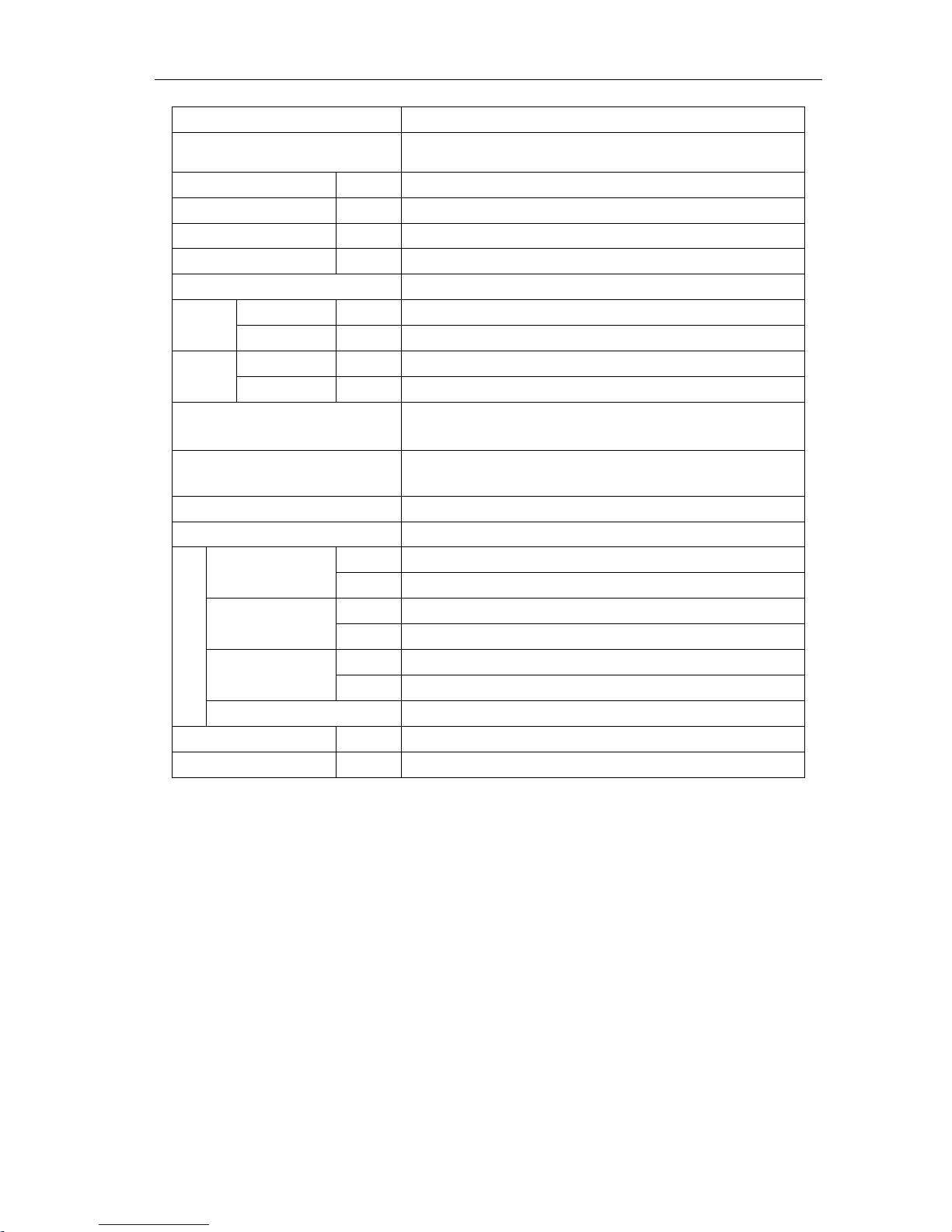
4.2 Product data of indoor
4.2.1 Duct Type
Model
INV(L)-R22P/Na-K
INV(L)-R25P/Na-K
INV(L)-R28P/Na-K
Cooling Capacity
kW
2.2
2.5
2.8
Btu
7506
8530
9554
Heating Capacity
kW
2.5
3.0
3.2
Btu
8530
10236
10918
Air Flow Rate
m3/h
450
450
570
CFM
265
265
336
Sound Pressure Level (H/L)
dB(A)
37/33
37/33
39/35
External Static Pressure
Pa
25
25
25
Power Supply
220-240V~50Hz
220-240V~50Hz
220-240V~50Hz
Fan Motor
Output
kW
0.02
0.02
0.02
Running Current
A
0.17
0.17
0.16
Connecting
Pipes
Gas Pipe
mm
φ9.52
φ9.52
φ9.52
inch
φ3/8"
φ3/8"
φ3/8"
Liquid Pipe
mm
φ6.35
φ6.35
φ6.35
inch
φ1/4"
φ1/4"
φ1/4"
Connection Method
Flare Connection
Flare Connection
Flare Connection
Drain Pipes
(External Dia. × Thickness)
mm
φ20×1.5
φ20×1.5
φ20×1.5
Unit Dimensions
(W×D×H)
mm
875×680×220
875×680×220
875×680×220
Package Dimensions
(W×D×H)
mm
1012×708×275
1012×708×275
1012×708×275
Weight(Net/Gross)
kg
27/31
27/31
27/31
Notes:
① The design of this unit comply with the national executing standard of GB/T 18837-2002;
② Refer to the product nameplate for parameters and specification of the unit;
③ The model with INVL code is cooling only unit; while the model with INV code is heat pump unit; the cooling only
units dose not have any parameters of performing heating;
④ The sound level is tested under circumstance of semi-anechoic chamber; the value of noise could be a little higher in
actual operation.
MODULAR D.C. INVERTER MULTI VRF PRODUCT
27
Model
INV(L)-R32P/Na-K
INV(L)-R36P/Na-K
INV(L)-R40P/Na-K
Cooling Capacity
kW
3.2
3.6
4.0
Btu
10919
12284
13649
Heating Capacity
kW
3.6
4.0
4.5
Btu
12283
13648
15354
Air Flow Rate
m3/h
570
570
840
CFM
336
336
494
Sound Pressure Level (H/L)
dB(A)
39/35
39/35
40/36
External Static Pressure
Pa
25
25
20
Power Supply
220-240V~50Hz
220-240V~50Hz
220-240V~50Hz
Fan Motor
Output
kW
0.02
0.02
0.07
Running Current
A
0.16
0.16
0.69
Connecting
Pipes
Gas Pipe
mm
φ12.7
φ12.7
φ12.7
inch
φ1/2"
φ1/2"
φ1/2"
Liquid Pipe
mm
φ6.35
φ6.35
φ6.35
inch
φ1/4"
φ1/4"
φ1/4"
Connection Method
Flare Connection
Flare Connection
Flare Connection
Drain Pipes
(External Dia. × Thickness)
mm
φ20×1.5
φ20×1.5
φ30×1.5
Unit Dimensions
(W×D×H)
mm
875×680×220
875×680×220
980×736×266
Package Dimensions
(W×D×H)
mm
1012×708×275
1012×708×275
1068×766×320
Weight(Net/Gross)
kg
27/31
27/31
36/39
Notes:
① The design of this unit comply with the national executing standard of GB/T 18837-2002;
② Refer to the product nameplate for parameters and specification of the unit;
③ The model with INVL code is cooling only unit; while the model with INV code is heat pump unit; the cooling only
units dose not have any parameters of performing heating;
④ The sound level is tested under circumstance of semi-anechoic chamber; the value of noise could be a little higher in
actual operation.
 Loading...