

INVENTOR IMCR8WZNa-M, IMCR10WZNa-M, IMCR22SNa-M, IMCR25SNa-M, IMCR12.5WZNa-M Service Manual
...
Service Manual
Service Manual
Service Manual
Mini Chiller

MINI CHILLER PRODUCT
2
PRODUCT INTRODUCTION ................................................................................... 3
1 MODELS LIST ............................................................................................................................. 3
1.1 Split Type ........................................................................................................................... 3
1.2 Integral Type ...................................................................................................................... 4
2 NOMENCLATURE ...................................................................................................................... 5
1.1 Split Type ........................................................................................................................... 5
1.2 Integral Type ...................................................................................................................... 5
3FUNCTION ................................................................................................................................... 5
4 PRODUCT DATA ......................................................................................................................... 6
4.1 Product Data at Rated C
ondition ........................................................................................ 6
4.2 Operation Range ................................................................................................................. 8
4.3 Pressure-loss Conversion C
hart ......................................................................................... 8
4.4 Electrical Data .................................................................................................................... 8
5 PIPING DIAGRAM ...................................................................................................................... 9
UNITS CONTROL .................................................................................................... 11
1 OPERATION FLOWCHAR
T ..................................................................................................... 11
1.1 Cooling Operation ............................................................................................................ 11
1.2 Heating Operation ............................................................................................................ 12
2 MAIN LOGIC ............................................................................................................................. 13
3 WIRED CONTROLLER ............................................................................................................ 15
3.2.2 Display View ................................................................................................................. 17
4 CONTROL WIRING DESIGN
................................................................................................... 19
UNITS INSTALLATION .......................................................................................... 22
1 UNITS INST
ALL ........................................................................................................................ 22
1.1 Installation Positions ........................................................................................................ 22
1.2 Matters need Attention ..................................................................................................... 22
1.3 DIMENSION DA
TA ........................................................................................................ 22
1.2 INSTALLATION CLEARANCE DA
TA ......................................................................... 25
2 WATER PIPING WORK
............................................................................................................ 28
2.1 Installation Procedure ....................................................................................................... 28
2.2 Matters of Attention ......................................................................................................... 28
2.3 Antifreeze ......................................................................................................................... 28
3 ELECTRIC WIRING WORK ..................................................................................................... 28
3.1 Wiring Principle
............................................................................................................... 28
3.2 Electric Wiring Design ..................................................................................................... 28
3.3 SPECIFICATION OF POWER CORD &
AIR SWITCH ................................................ 28
3.4 WIRING DIAGRAM ....................................................................................................... 29
3.4.1 Wiring Diagram-Split T
ype .......................................................................................... 29
3.4.2 Wiring Diagram- Integral Type ..................................................................................... 31
UNITS MAINTENANCE .......................................................................................... 34
1 ERROR CODE LIST .................................................................................................................. 34
2 FLOW CHART OF TROUBLESHOOTING.............................................................................. 34
3 DISASSEMBLY AND ASSEMBLY PROCEDURE OF MAIN P
ARTS .................................... 36
3.1 Split Type ......................................................................................................................... 36
3.2 Integral Type .................................................................................................................... 46
4 EXPLODED VIEWS AND P
ART LIST ..................................................................................... 50
4.1 Exploded Views and Par
ts List- Split Type ...................................................................... 50
4.2 Exploded Views and Parts List- Integral Type ................................................................. 61

MINI CHILLER PRODUCT
3
PRODUCT INTRODUCTION
1 MODELS LIST
1.1 Split Type
Model
Nominal
Capacity
Power Supply
Appearance
Refrigerant Model Name kW (V,Ph,Hz)
Outdoor Unit indoor Unit
R410A
IMCR8WZNa-M
8.0
380~415V
3Ph 50Hz
IMCR10WZNa-M 10.0
IMCR12.5WZNa-M
12.5
IMCR15WZNa-M
15.0
Note:1Ton =12000Btu/h = 3.517kW
MINI CHILLER PRODUCT
4
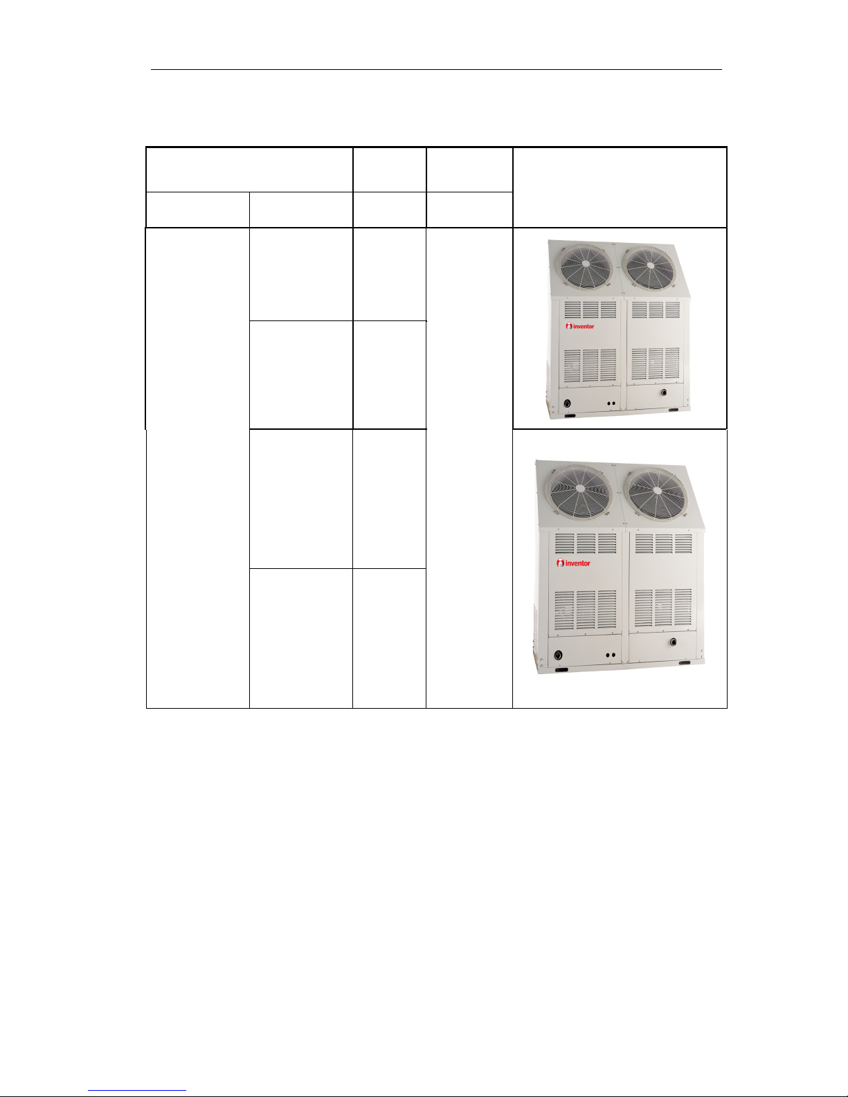
1.2 Integral Type
Model
Nominal
Capacity
Power Supply
Appearance
Refrigerant Model Name kW (V,Ph,Hz)
R410A
IMCR22SNa-M 22
380~415V
3Ph 50Hz
IMCR25SNa-M
25
IMCR35SNa-M
35
IMCR45SNa-M
45
Note:1Ton =12000Btu/h = 3.517kW
MINI CHILLER PRODUCT
5
2 NOMENCLATURE
1.1 Split Type
IMC R 15 W Z Na - M
1 2 3 4 5 6 7
NO. Description Options
1 Mini chiller 2 Product type R=Heat pump
3 Nominal Cooling Capacity
8=8kW
10=10 kW
12.5= 12.5kW
15= 15kW
4 Struct type
Default=Vertical type
W=Horizontal type
5 Product configuration Z=Combination
6 Refrigerant Na=R410A, Default=R22
7 Voltage
M=380~415V 3Ph 50Hz
1.2 Integral Type
IMC R 35 S Na - M
1 2 3 4 5 6
NO. Description Options
1 Mini chiller 2 Product type R=Heat pump
3 Nominal Cooling Capacity
22=22kW
25=25kW
35=35kW
45=45kW
4 Refrigeration Circuits
Default=One circuit
S=Twin circuit
5 Refrigerant Na=R410A, Default=R22
6 Voltage
M=380~415V 3Ph 50Hz
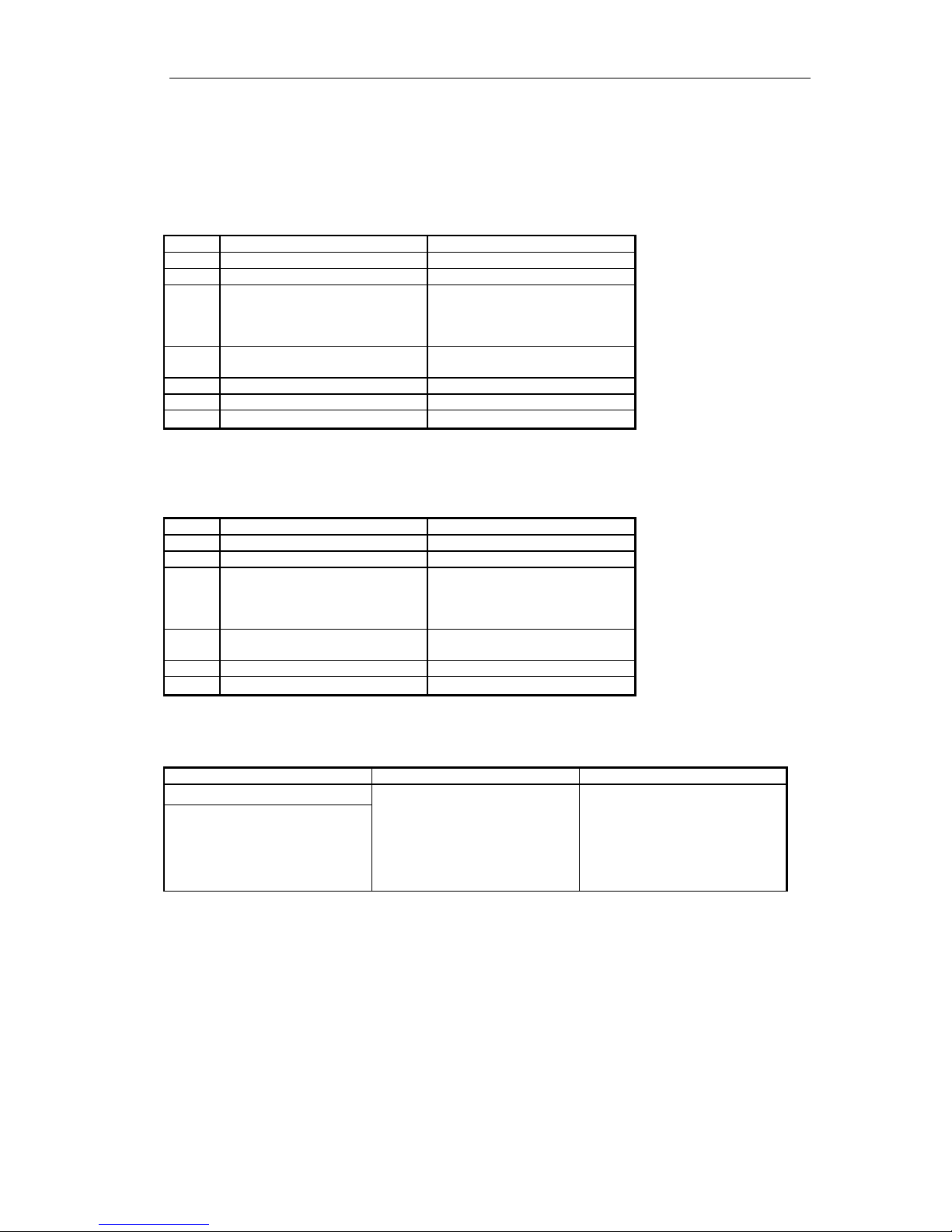
3FUNCTION
Indoor Unit Type Function Description
Split Type
Heating
Interface kit for up to 16 indoor
units
Memory restart
Two circuits optimized design
Low noise design
Safety and reliability thanks to
advance compressor balance control
Integral Type
MINI CHILLER PRODUCT
6
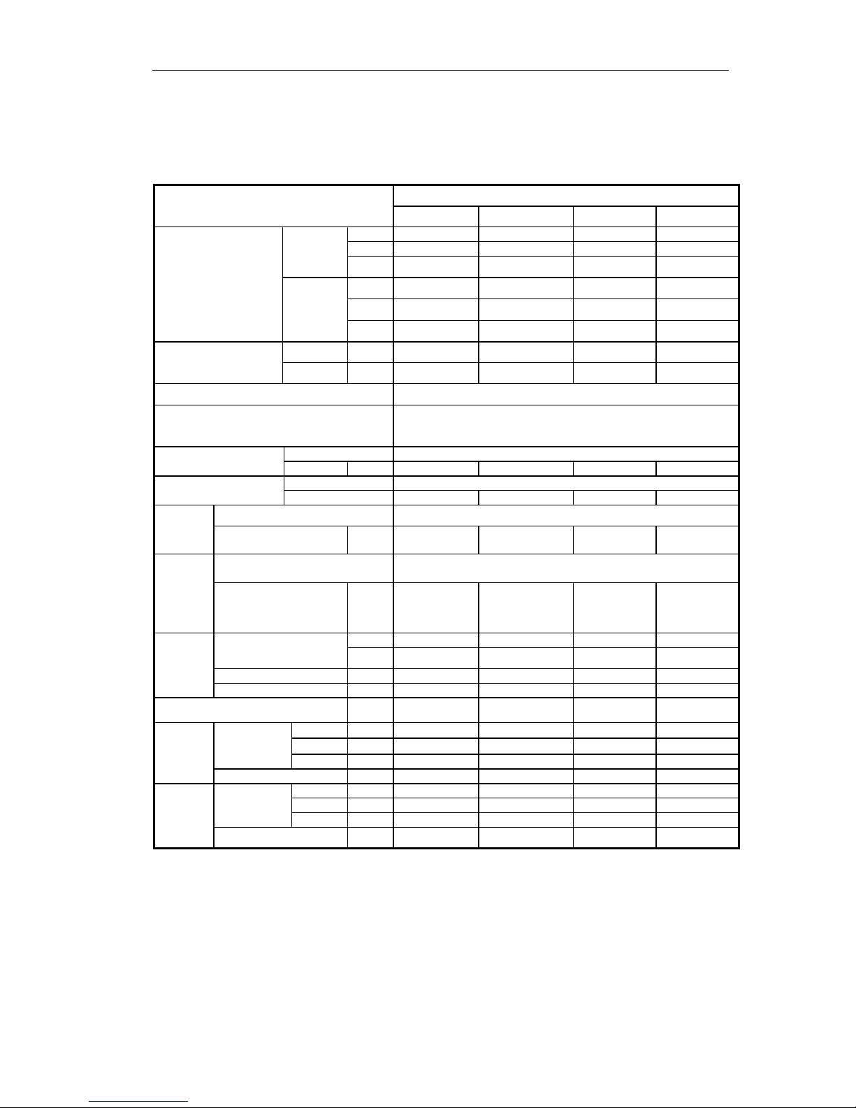
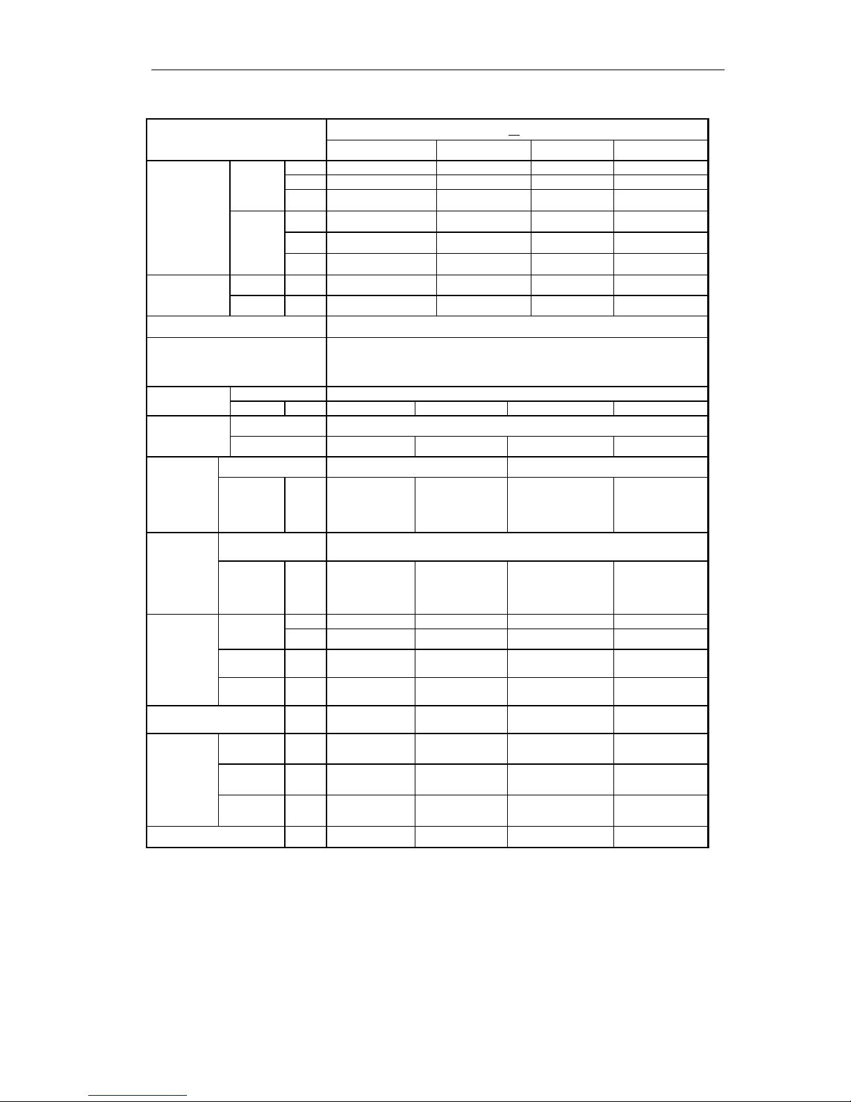
4 PRODUCT DATA
4.1 Product Data at Rated Condition
4.1.1 Split Type
Models
IMCR_WZNa-M
8 10 12.5 15
Nominal Capacity
Cooling
kW 8 10 13 15
Btu/h 27300 34120 42650 51180
RT 2.3 2.9 3.6 4.3
Heating
kW 9 11 15.5 16
Btu/h 307000 37550 44356 54600
RT 2.6 3.1 3.7 4.6
Power
Consumption
Cooling kW 3.3 4.4 5.2 5.6
Heating kW 3.2 4.2 5.0 5.5
Power Supply 380~415V,3Ph,50Hz
Safeties
High/Low pressure switch, compressor thermal protection, over
current protection, lose of phase/anti-phase protection,
antifreeze protection, water flow switch
Refrigerant
Type R4 10A
Charge kg 3.1 3.55 3.6 5.5
Compressor
Type scroll
NO. 1 1 1 1
Evaporator
Heat Exchanger Tube-in-Tube
Water In/Out Pipe
Diameter
Inch 1’ 1’ 1’ 1’
Condenser
Heat Exchanger Aluminum fin-copper tube
Fan Motor Power Input
kW 0.2 0.14 0.14 0.2
Pump
Water Flow
L/s 0.36 0.5 0.56 0.72
GPM 5.78 7.94 8.83 11.48
Delivery Lift m 18 18 18 18
Power Input kW 0.55 0.55 0.55 0.55
Expansion Vessel Volume L 5 5 5 5
Indoor
Unit
Unit /
Packing
Dimension
Height mm 288/385 288/385 288/385 288/385
Width mm 1100/1285 1100/1285 1100/1285 1100/1285
Depth mm 450/682 450/682 450/682 450/682
Net/Gross Weights 84/96 84/96 84/96 84/96
Outdoor
Unit
Unit /
Packing
Dimension
Height mm 840/985 1250/1385 1250/1385 1250/1385
Width mm 950/1100 950/1110 950/1110 1100/1260
Depth mm 412/450 412/450 412/450 412/450
Net / Gross Weights
90/100 112/123 115/126 123/134
MINI CHILLER PRODUCT
7
4.1.2 Integral Type
Models
IMCR
SNa-M
22 25 35 45
Nominal
Capacity
Cooling
kW 22 25 35 43
Btu/h 64828 85300 119420 153540
RT 5.4 7.1 10 13
Heating
kW 26 27 37 50
Btu/h 71650 92124 126250 184248
RT 6 7.7 10.6 15.4
Power
Consumption
Cooling kW 8.7 9.0 11.8 17.1
Heating kW 8.8 8.85 12.3 16.6
Power Supply 380~415V 3Ph 50Hz
Safeties
High/Low pressure switch, compressor thermal protection, over current
protection, lose of phase/anti-phase protection, antifreeze protection,
water flow switch
Refrigerant
Type R4 10A
Charge kg 3.6X2 4.8X2 6.5X2 7.3X2
Compressor
Type scroll
NO. 2 2 2 2
Evaporator
Heat Exchanger Tube-in-Tube Shell and tube
Water
In/Out
Pipe
Diameter
Inch 1’ 1’ 1-1/2’ 1-1/2’
Condenser
Heat Exchanger Aluminum fin-copper tube
Fan
Motor
Power
Input
kW 0.4 0.4 0.6 0.8
Pump
Water
Flow
L/s 0.9 1.2 1.4 2.2
GPM 14.5 18.9 22.9 35.2
Delivery
Lift
m 22 24 25 27
Power
Input
kW 0.75 0.75 1.5 1.5
Expansion Vessel
Volume
L 8 8 8 8
Unit / Packing
Dimension
Height mm 1850/1960 1850/1960 1760/1870 1761/1870
Width mm 1460/1540 1460/1540 1750/1830 1750/1830
Depth mm 530/610 530/610 800/880 800/880
Net/Gross Weights
kg
370/380 390/400 680/690 755/765
NOTE:
1、Cooling capacity is based on the following conditions:leaving chilled water temp.7℃,outdoor air temp.35℃
2、Heating capacity is based on the following conditions:leaving warmed water temp.45℃, outdoor air
temp.7℃
3、Water flow range for operation must be from 70% to 120% of the rated water flow。
4、The maximum allowable pressure for water pipe is 0.9MPa
MINI CHILLER PRODUCT
8
4.2 Operation Range
Mode
Range of Outdoor Temperature℃ (℉)
Cooling 16~48
Heating -15~28
4.3 Pressure-loss Conversion Chart
Water F l o w (m3/h) 1.2 1.4 1.7
1.9 2.0
The percentage (%) 70 80 100 110 120
Loss of Pressure (kPa) 200 100 0
100 200
NOTE:
The percentage is contrasted to nominal water flow.
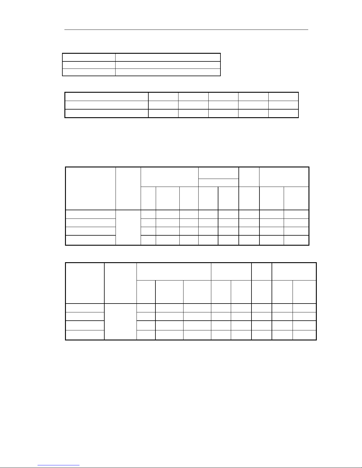
4.4 Electrical Data
4.4
.1 Split Type
Model
Rated
Power
Supply
Compressor
Fan Motor
Pump Total
Outdoor
NO.
LRA
each
(A)
MRC
each
(A)
NO.
MRC
(A)
MRC
(A)
MRC
(A)
NRC
(A)
IMCR8WZNa-M
380~41
5V 3Ph
50Hz
1 97 21.2 1 1.5 1.0 23.4 17
IMCR10WZNa-M
2 49 13.2 2 2 1.0 31 22
IMCR12.5WZNa-M
2 52 16.1 2 3 1.0 39 28
IMCR15WZNa-M
2 69 17 2 3 1.0 47 33.5
4.4.2 Integral Type
Model
Rated
Power
Supply
Compressor Fan Motor Pump Total
NO.
LRA
each
(A)
MRC
each
(A)
NO.
MRC
(A)
MRC
(A)
MRC
(A)
NRC
(A)
IMCR22SNa-M
380~415V
3Ph 50Hz
2 42 9.5 2 5 1.3 19.5 14
IMCR25SNa-M`
2 56 11.2 2 5 1.3 23.5 16.8
IMCR35SNa-M
2 101 15.3 2 7.5 2.7 42 30
IMCR45SNa-M
2 110 21.4 2 7.5 2.7 54 38.5
Notes:
LRA: Locked rotor amps (A)
MRC: Maximum running current (A)
NRC: Nominal running current (A)
MINI CHILLER PRODUCT
9
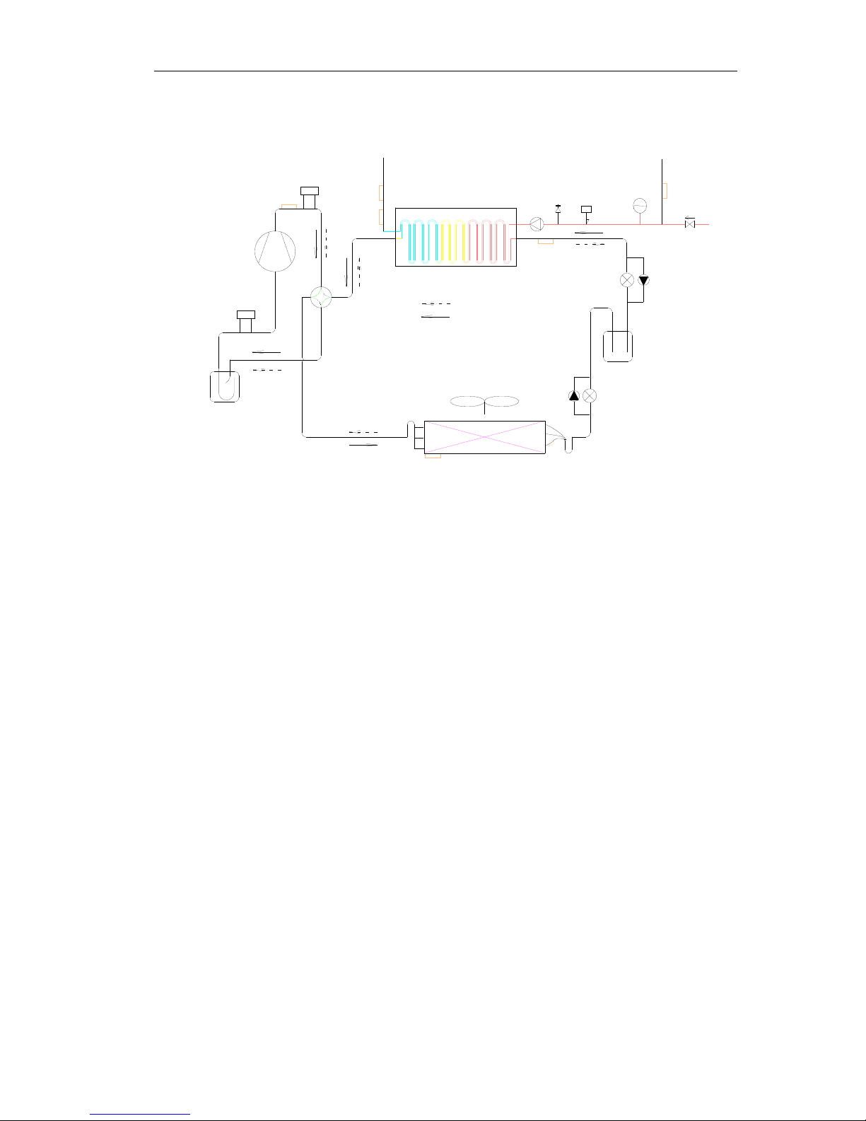
5 PIPING DIAGRAM
Heating circuit
Cooling circuit
Pump
Relief
valve
Flow
switch
Expansion
drum
High pressure
tank
Aluminum fin-copper tube
coil
Four-way valve
Shell and tube heat
exchanger
Inlet
Outlet
High-pressure
switch
Compressor
Low-pressure
switch
Liquid-gas separator
F

INVENTOR COMMERCIAL AIR CONDITIONERS MINI
CHILLER
10
CONTROL
MINI CHILLER CONTROL
11
UNITS CONTROL
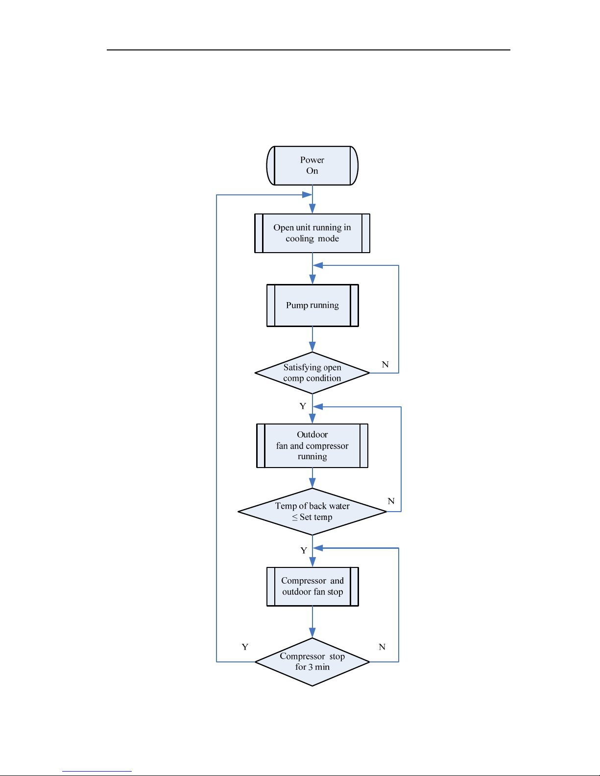
1 OPERATION FLOWCHART
1.1 Cooling Operation
MINI CHILLER CONTROL
12
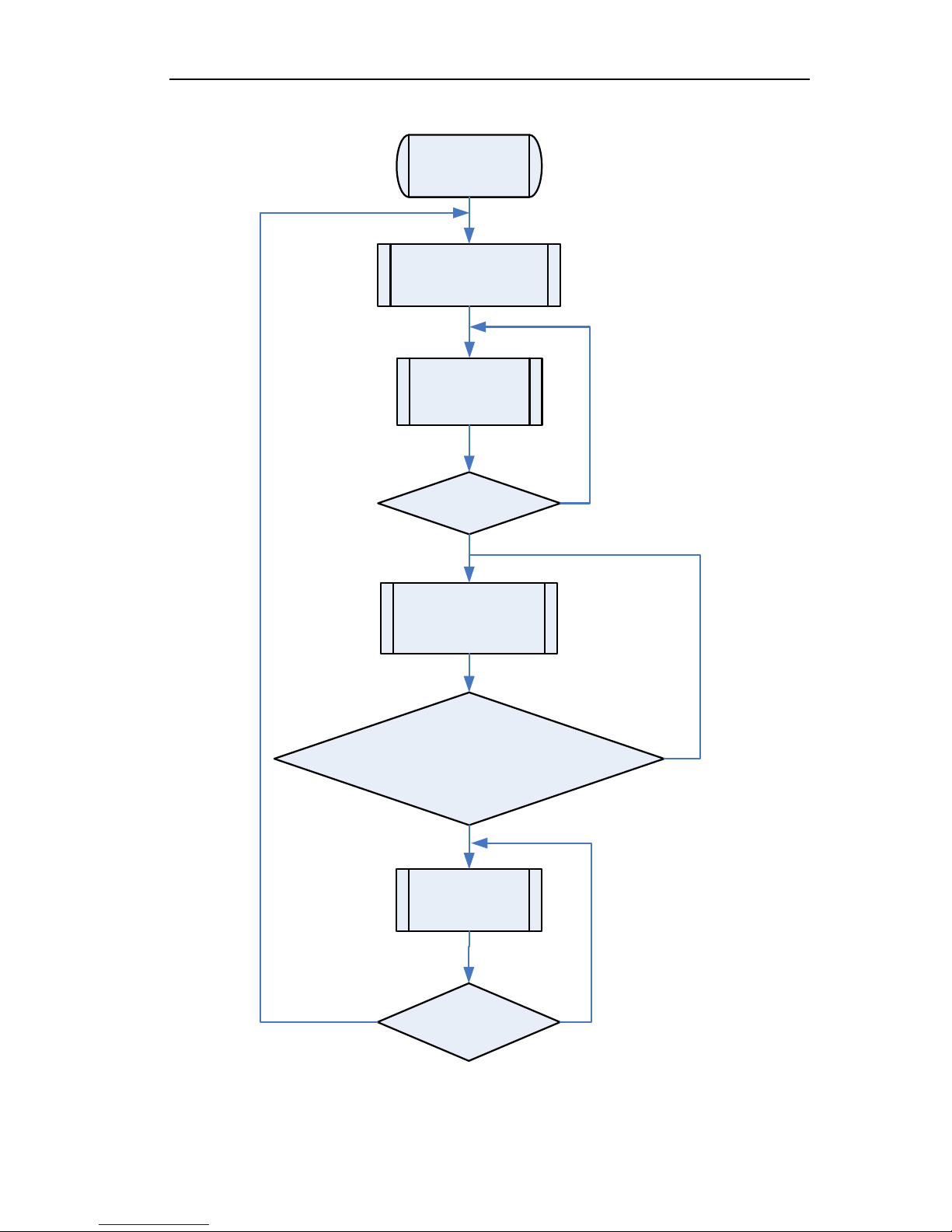
1.2 Heating Operation
Power
On
Open unit running in
heating mode
Satisfying open
comp condition
Pump running
Outdoor
fan, compressor and
valve running
Temp of back water
≥ (Set temp + 5) (spilt type)
Temp of back water
≥ (Set temp + 6) (Integral type)
Compressor and
outdoor fan stop
Compressor stop
for 3 min
NY
N
Y
Y
N
MINI CHILLER CONTROL
13
2 MAIN LOGIC
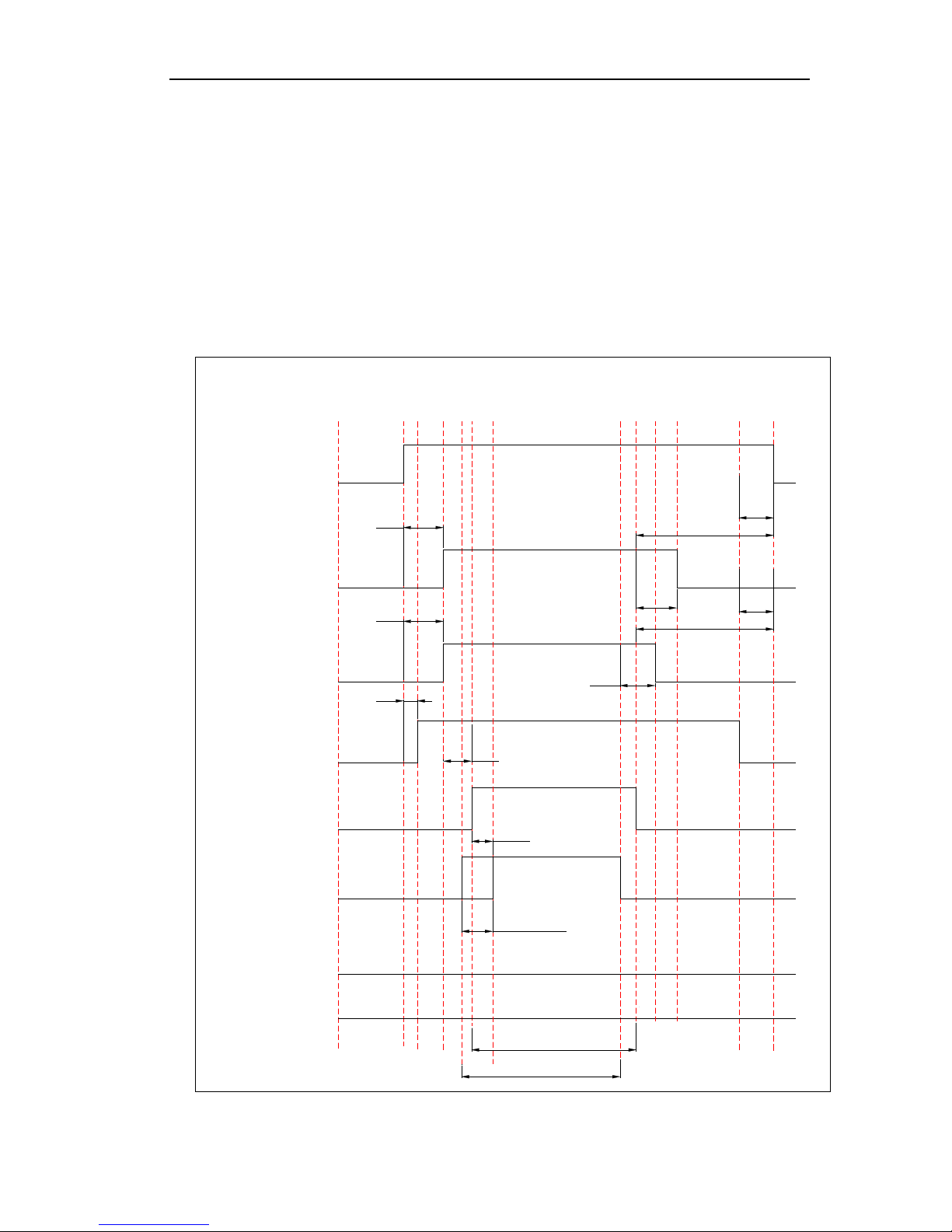
2.1 Cooling Mode
When press ON button, if the outdoor temperature is over 16℃, it starts the water pump first After
30s, if the outlet water temperature meets the cooling running requirements, it starts the fans of outdoor
unit. Then the compressor will run after 15s. During the period of cooling, the unit will turn off if the
outlet water temperature meets the stopping requirements and the running time of compressor is over
the shortest running time required. The fans of outdoor unit will stop after 15s.
If the outdoor temperature is below 16℃, the unit will stop, and turn off all loads except the water
pump.
Turn on
Turn off
Pump
1
Fan 1
Fan 2
Flow Switch
Compr essor
1
Compr ess or 2
Four-way valve 1
Four-way valve 2
30S
30S
5S
15S
10min
15>Tout>12
14>Tout>7
15>Tout>8
Check if flow switch is ok
15S
15S
5S
3min
3min
5S
When it is turned off
When it is turned off
MINI CHILLER CONTROL
14
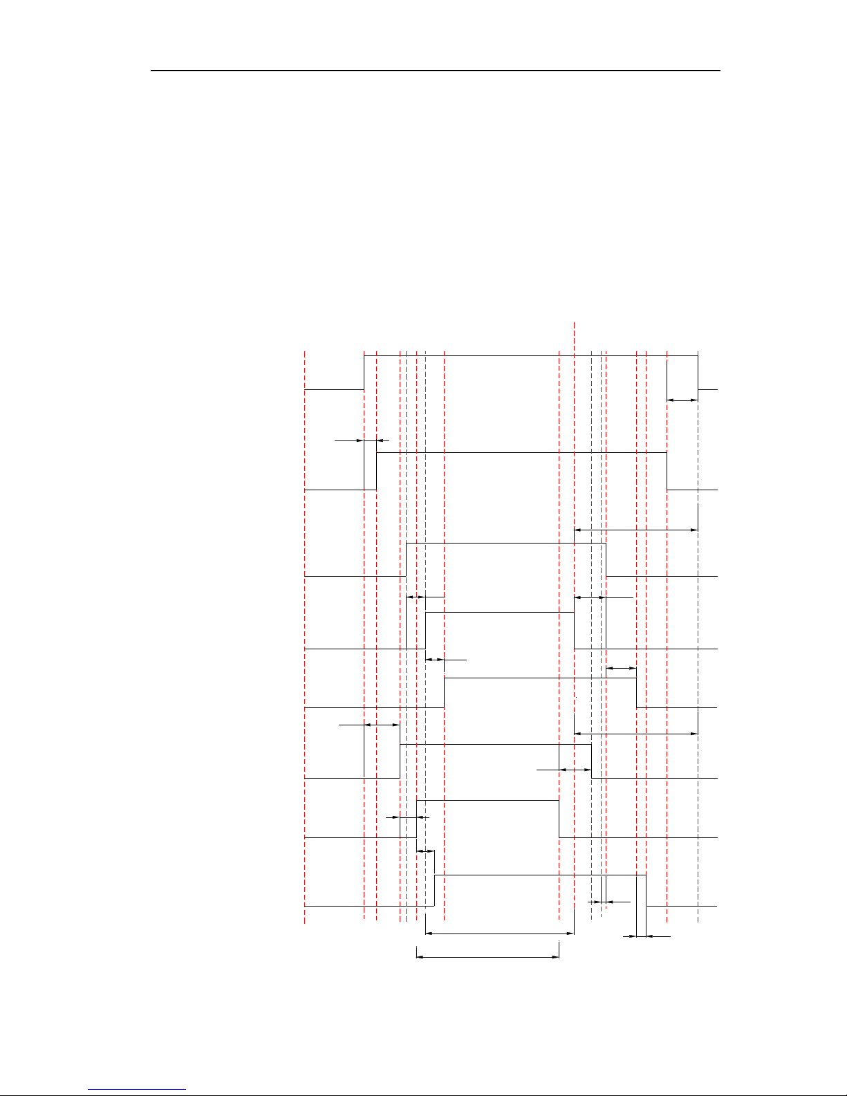
2.2 Heating Mode
When press ON button, if the outdoor temperature is below 28℃, it starts the water pump first After
30s, if the outlet water temperature meets the heating running requirements, it starts the fans of outdoor
unit. Then the compressor will run after 15s. During the period of cooling, the unit will turn off if the
outlet water temperature meets the stopping requirements and the running time of compressor is over
the shortest running time required. The fans of outdoor unit will stop after 15s.
If the outdoor temperature is over 28℃, the unit will stop, and turn off all loads except the water
pump.
Pump
Turn
off
Turn
on
Flow Switch
Fan 1
Compressor 1
Four-way Valve1
Fan 2
Compressor 2
Four-way Valve 2
15S
Check if flow switch is ok
5S
3min
When it is turned off
15S
30S
3min
When it is turned off
5S
15S
30S
5S
15S
2S
5S
15S
48<Tout<54
46<Tout<52
MINI CHILLER CONTROL
15
2.3 Defrosting Mode
The condition of start defrosting mode:
Under heating mode, if the accumulative running time of compressor is over the set interval time
of defrosting( default 45min),and the defrosting temperature is lower than the set starting
temperature(default -4℃) ,the unit will start running defrosting mode, and the 4-way valve will shut
off and the outdoor fan will stop after 2s.
The condition of quit defrosting mode:
Under defrosting mode, if the continual defrosting time is over the set continual time of defrosting
(default 8min),and the defrosting temperature is over the set stopping temperature(default 20℃) ,the
unit will restart running heating mode, and the 4-way valve will turn on and the outdoor fan will run.
3 WIRED CONTROLLER
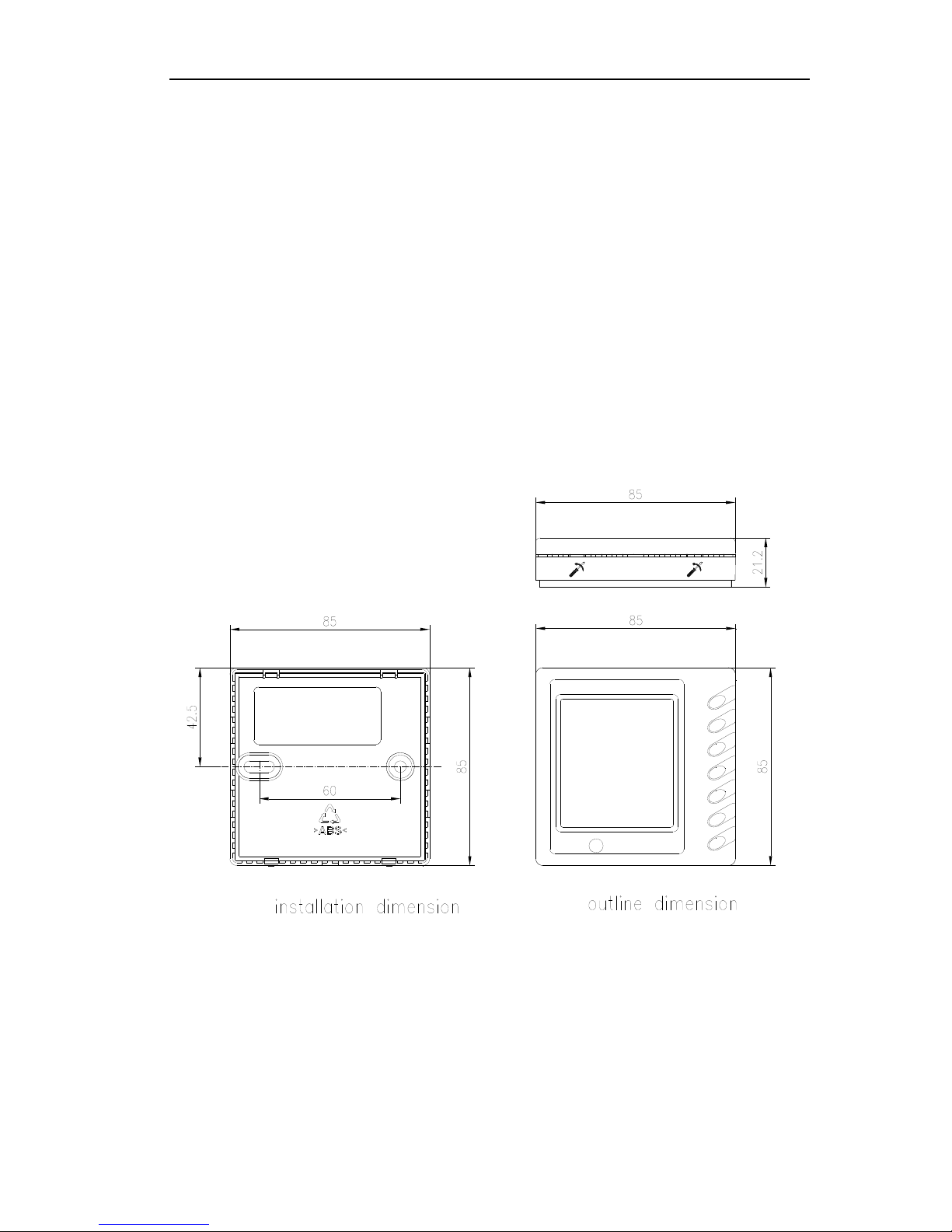
3.1 Dimension
3.2 Function
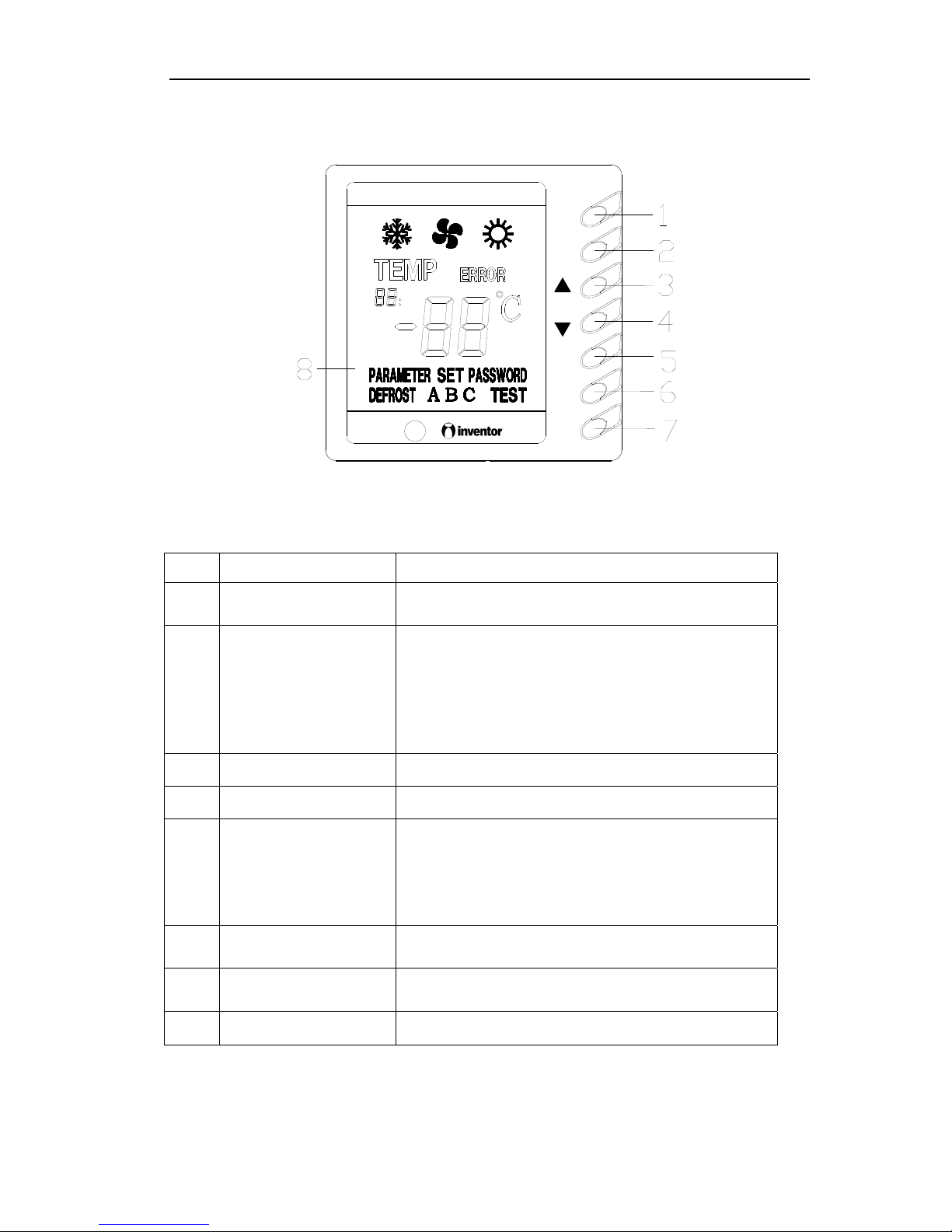
3.2.1 Operation View
MINI CHILLER CONTROL
16
MODE
CHECK
ON
QUIT
OFF
NO. Name Function description
1 MODE button
It can switch between cooling and heating, this button is
available only on cooling and heating unit.
2 CHECK button
Press it once under normal state to enter check mode,
under check mode, press this button when “17” is
displayed can change the value of “17”. Under parameter
set mode, press this once can switch the adjusting objection
between parameter and value, press this button for long
(about 5s) to save and quit this parameter setting.
3 Increasing button
To increase present set value or change set/check object.
4 Decreasing button
To decrease present set value or change set/check object.
5 QUIT button
Under Set and Check mode, press it once to quit this mode.
Under parameter set mode, this set value would not be
saved. Press this button for long (about 5s) to set sound,
and make sound switches between always on and always
off.
6 ON button
To turn on the unit; when under compel operation, press
once to quit compel operation.
7 OFF button
To turn off the unit; press it once to quit compel operation
when the unit is under compel operation.
8 LCD display Display information of the unit.
Note:
(1) Turn On, Off Auxiliary Heater: It is only available for heat pump unit. Press CHECK once to
MINI CHILLER CONTROL
17
enter Check mode. Press ▲ and ▼ to change check object, press CHECK again till the present
check object becomes “17”, value “17” switches between 01/03 (auxiliary heater on) and 00/02
(auxiliary heater off). That is 00 Off —>01 On —>00 Off, or 02 Off —>03 On —>02 Off.
(2) Check Parameter: After electrify for 20s, press QUIT then ▲ to enter parameter checking mode.
Under this mode, Auxiliary display area shows the checking object, Main display area displays
the value for the checking object. Press ▲ and ▼ to change the checking object. Press QUIT to
quit from the check mode.
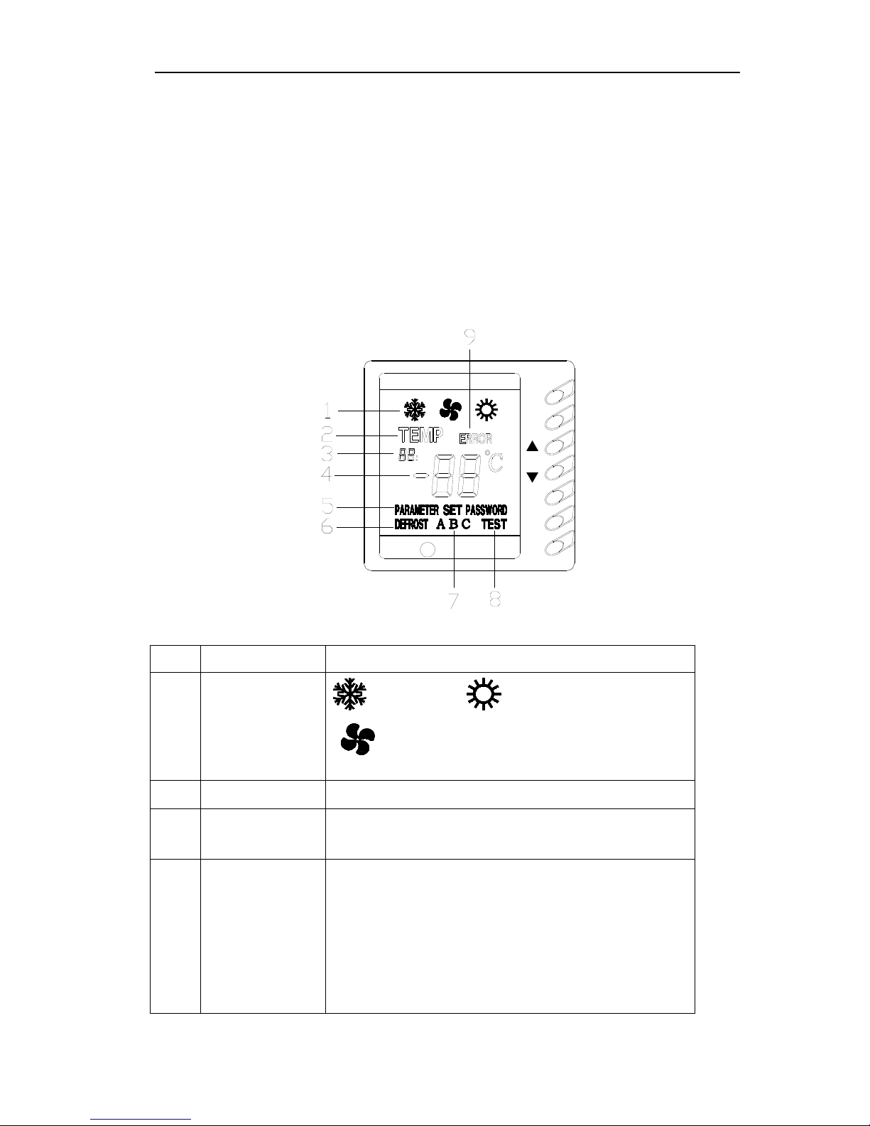
3.2.2 Display View
OFF
QUIT
ON
CHECK
MODE
NO. Name Function description
1 Running mode display
: cooling mode, : heating mode,
: reserved
2 Temp display It shows temperature value displays at main display area.
3 Auxiliary display area
It contains 2 numbers and a comma, for showing temperature and
number of parameter at main display area. It only displays when under
Check mode and Parameter checking mode.
4 Main display area
It contains a minus, 2 numbers and 1 temperature unit, for displaying
value of temperature and parameter (temperature or time value) and error
code. When temperature value is displayed, it shows value in algorism
and temperature unit; when time is displayed, it shows algorism value but
no temperature unit (default unit is min); when it is code, it displays
specific error (refer to Malfunction Error List) but no temperature unit.
Individual temperature or parameter may exceed 99, then adopt AX for
100~109, bX for 110~119, CX for 120~129, dX for 130~139, EX for
140~149, FX for 150~159, and X stands for a number between 0~9.

MINI CHILLER CONTROL
18
Under normal state, it shows temperature for back water.
5 Parameter display
It means the value shown at present main display area is parameter. It
shows only under Parameter Check mode.
6 Defrost display It displays when defrosting, otherwise it doesn’t displays.
7 System ID
It displays when system or compressor orders, for showing which system
is defrosting.
8 Testing display For testing, it displays under compel operation.
9 Error code display
It shows the error code displayed on Main Display Area. It displays when
there is error at system or communication.
Caution:
(1) When unit is off, it displays only temperature of back water. When unit is on, under normal state,
if there is no error, it displays temperature of back water, if there is error, it displays error code;
when there is no operation after 60s of pressing the button, it quit back to normal state display
automatically.
(2) Auto antifreeze operation display (only for heat pump unit)
When auto antifreeze function is started and relevant conditions are satisfied, unit begins auto
antifreeze operation. At this time, LCD main display area displays code d2 (if there is error it
displays error code).
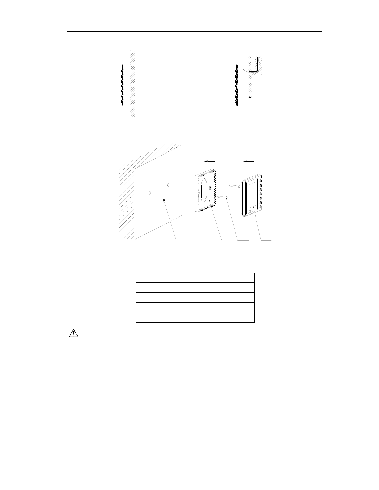
3.3 Installation
1. First select an installation position. According to the size of the communication line of the wire
controller, leave a recess or a embedded wire hole to bury the communication line.
2. If the communication line between the wire controller (85×85×20) and the indoor unit is
surface-mounted, use 1# PVC pipe and make matching recess in the wall (refer to Figure 6); If
concealed installation is adopted, 1# PVC pipe can be used (Refer to Figure 7).
3. No matter if surface mounting or concealed mounting is selected, it is required to drill 2 holes (in
the same level) which distance shall be the same as the distance (60mm) of installation holes in
the bottom plate of the wire controller. Then insert a wood plug into each hole. Fix the bottom
plate of the wire controller to the wall by using the two holes. Plug the communication line onto
the control panel. Lastly install the panel of the wire controller.
Caution:
During the installation of the bottom plate of the wire controller, pay attention to the direction of
the bottom plate. The plate’s side with two notches must be at the lower position, and otherwise the
panel of the wire controller cannot be correctly installed.
MINI CHILLER CONTROL
19
PVC pipe
Fig6:Surface Mounting of Cable Fig7:Concealed mounting of Cable
1 324
Fig 8 Schematic Diagram of Installation
No. Name
1 Wall Surface
2 Bottom Plate of Wire Controller
3 Screw M4X10
4 Panel of Wire Controller
Caution:
1. The communication distance between the main board and the wire controller can be as far as 20m
(The standard distance is 8m).
2. The wire controller shall not be installed in a place where there is water drop or large amount of
water vapor.
4 CONTROL WIRING DESIGN
MINI CHILLER CONTROL
20
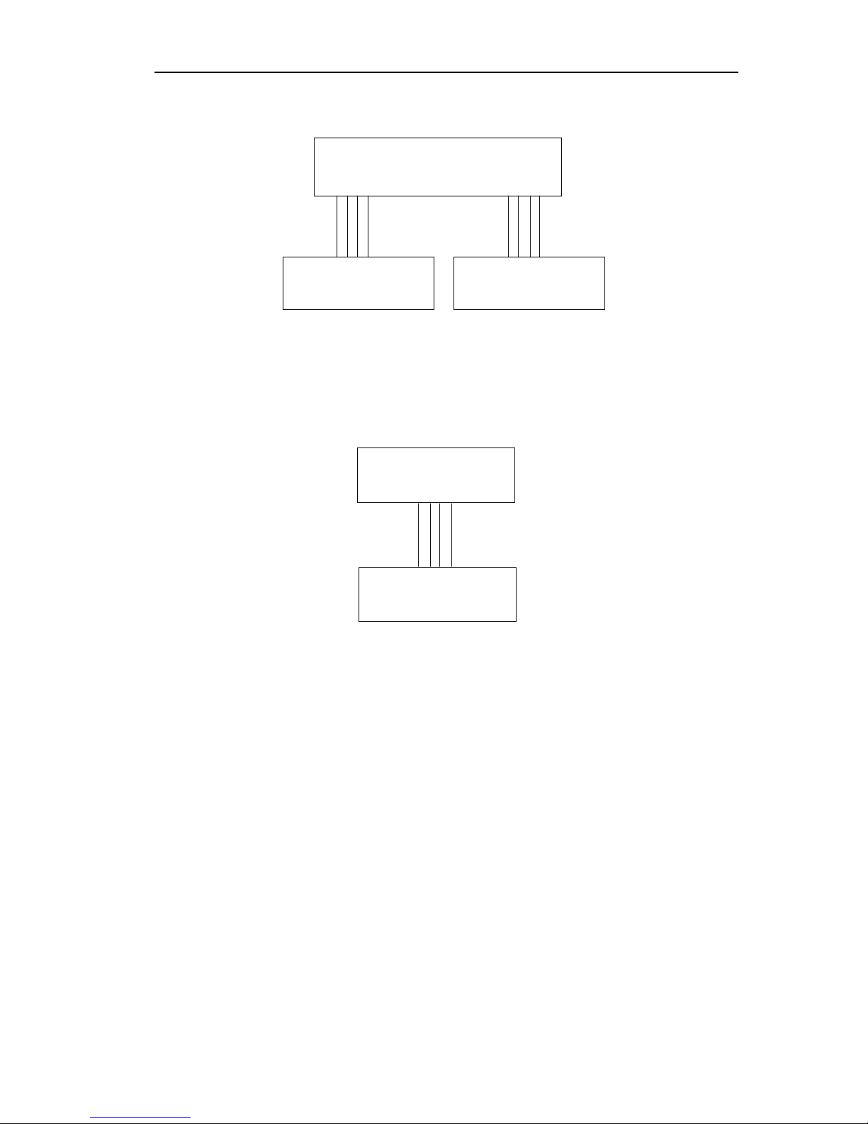
twisted-pair
twisted-pair
X17J1
CN2
CN1
Outdoor Unit Controller
Manual Unit Controller
Indoor Unit Controller
The controllers of the split type unit include manual controller, indoor unit controller and outdoor
unit controller. The indoor unit controller communications with manual controller and outdoor unit
controller in RS485. The indoor unit controller connects manual controller with 4-line twisted-pair.
Similarly, the indoor unit controller connects outdoor unit controller with 4-line twisted-pair.
Indoor Unit Controller
Manual Unit Controller
Outdoor Unit Controller
J1
X17
twisted-pair
The controllers of the Integral type unit include manual controller and outdoor unit controller. The
manual controller communications with outdoor unit controller in RS485. The manual controller
connects outdoor unit controller with 4-line twisted-pair.
 Loading...