

INVENTOR IMCR8WZNa-M, IMCR10WZNa-M, IMCR22SNa-M, IMCR25SNa-M, IMCR12.5WZNa-M Service Manual
...
Service Manual
Service Manual
Service Manual
Mini Chiller

MINI CHILLER PRODUCT
2
PRODUCT INTRODUCTION ................................................................................... 3
1 MODELS LIST ............................................................................................................................. 3
1.1 Split Type ........................................................................................................................... 3
1.2 Integral Type ...................................................................................................................... 4
2 NOMENCLATURE ...................................................................................................................... 5
1.1 Split Type ........................................................................................................................... 5
1.2 Integral Type ...................................................................................................................... 5
3FUNCTION ................................................................................................................................... 5
4 PRODUCT DATA ......................................................................................................................... 6
4.1 Product Data at Rated C
ondition ........................................................................................ 6
4.2 Operation Range ................................................................................................................. 8
4.3 Pressure-loss Conversion C
hart ......................................................................................... 8
4.4 Electrical Data .................................................................................................................... 8
5 PIPING DIAGRAM ...................................................................................................................... 9
UNITS CONTROL .................................................................................................... 11
1 OPERATION FLOWCHAR
T ..................................................................................................... 11
1.1 Cooling Operation ............................................................................................................ 11
1.2 Heating Operation ............................................................................................................ 12
2 MAIN LOGIC ............................................................................................................................. 13
3 WIRED CONTROLLER ............................................................................................................ 15
3.2.2 Display View ................................................................................................................. 17
4 CONTROL WIRING DESIGN
................................................................................................... 19
UNITS INSTALLATION .......................................................................................... 22
1 UNITS INST
ALL ........................................................................................................................ 22
1.1 Installation Positions ........................................................................................................ 22
1.2 Matters need Attention ..................................................................................................... 22
1.3 DIMENSION DA
TA ........................................................................................................ 22
1.2 INSTALLATION CLEARANCE DA
TA ......................................................................... 25
2 WATER PIPING WORK
............................................................................................................ 28
2.1 Installation Procedure ....................................................................................................... 28
2.2 Matters of Attention ......................................................................................................... 28
2.3 Antifreeze ......................................................................................................................... 28
3 ELECTRIC WIRING WORK ..................................................................................................... 28
3.1 Wiring Principle
............................................................................................................... 28
3.2 Electric Wiring Design ..................................................................................................... 28
3.3 SPECIFICATION OF POWER CORD &
AIR SWITCH ................................................ 28
3.4 WIRING DIAGRAM ....................................................................................................... 29
3.4.1 Wiring Diagram-Split T
ype .......................................................................................... 29
3.4.2 Wiring Diagram- Integral Type ..................................................................................... 31
UNITS MAINTENANCE .......................................................................................... 34
1 ERROR CODE LIST .................................................................................................................. 34
2 FLOW CHART OF TROUBLESHOOTING.............................................................................. 34
3 DISASSEMBLY AND ASSEMBLY PROCEDURE OF MAIN P
ARTS .................................... 36
3.1 Split Type ......................................................................................................................... 36
3.2 Integral Type .................................................................................................................... 46
4 EXPLODED VIEWS AND P
ART LIST ..................................................................................... 50
4.1 Exploded Views and Par
ts List- Split Type ...................................................................... 50
4.2 Exploded Views and Parts List- Integral Type ................................................................. 61

MINI CHILLER PRODUCT
3
PRODUCT INTRODUCTION
1 MODELS LIST
1.1 Split Type
Model
Nominal
Capacity
Power Supply
Appearance
Refrigerant Model Name kW (V,Ph,Hz)
Outdoor Unit indoor Unit
R410A
IMCR8WZNa-M
8.0
380~415V
3Ph 50Hz
IMCR10WZNa-M 10.0
IMCR12.5WZNa-M
12.5
IMCR15WZNa-M
15.0
Note:1Ton =12000Btu/h = 3.517kW
MINI CHILLER PRODUCT
4
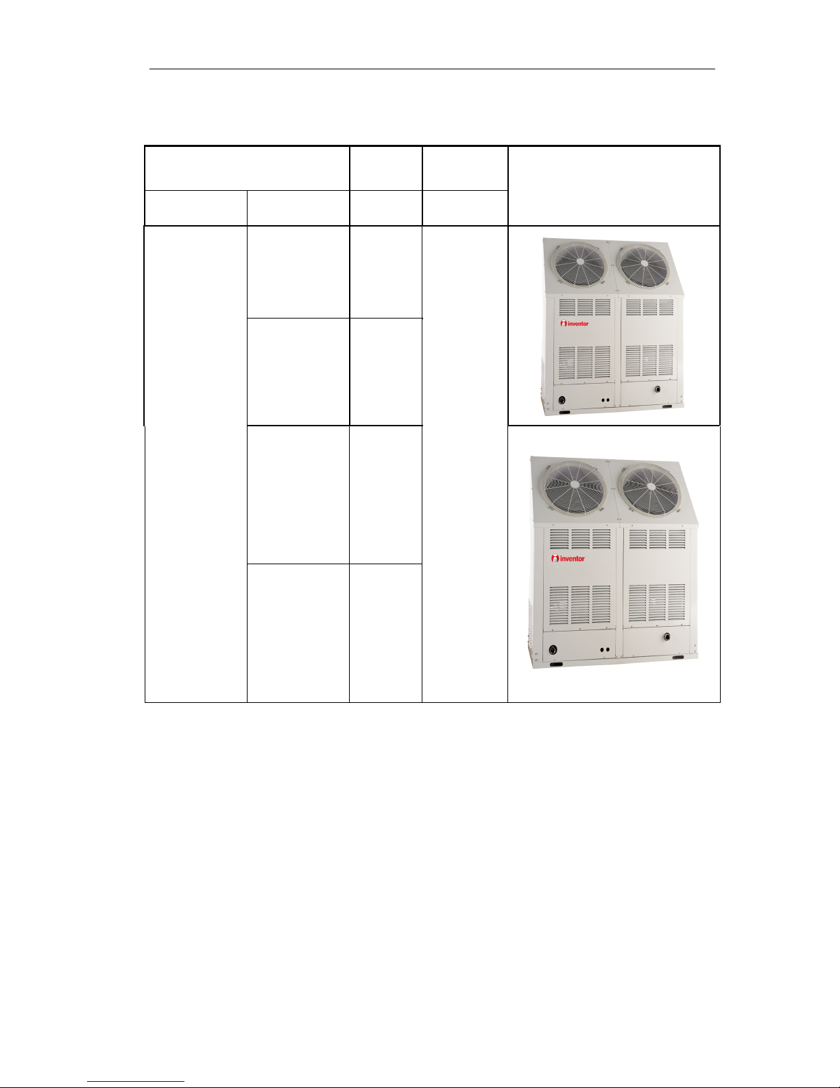
1.2 Integral Type
Model
Nominal
Capacity
Power Supply
Appearance
Refrigerant Model Name kW (V,Ph,Hz)
R410A
IMCR22SNa-M 22
380~415V
3Ph 50Hz
IMCR25SNa-M
25
IMCR35SNa-M
35
IMCR45SNa-M
45
Note:1Ton =12000Btu/h = 3.517kW
MINI CHILLER PRODUCT
5
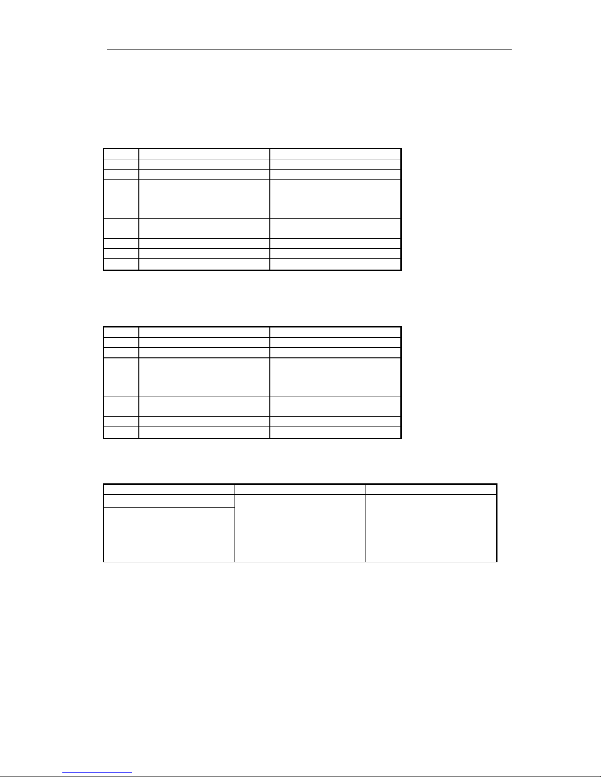
2 NOMENCLATURE
1.1 Split Type
IMC R 15 W Z Na - M
1 2 3 4 5 6 7
NO. Description Options
1 Mini chiller 2 Product type R=Heat pump
3 Nominal Cooling Capacity
8=8kW
10=10 kW
12.5= 12.5kW
15= 15kW
4 Struct type
Default=Vertical type
W=Horizontal type
5 Product configuration Z=Combination
6 Refrigerant Na=R410A, Default=R22
7 Voltage
M=380~415V 3Ph 50Hz
1.2 Integral Type
IMC R 35 S Na - M
1 2 3 4 5 6
NO. Description Options
1 Mini chiller 2 Product type R=Heat pump
3 Nominal Cooling Capacity
22=22kW
25=25kW
35=35kW
45=45kW
4 Refrigeration Circuits
Default=One circuit
S=Twin circuit
5 Refrigerant Na=R410A, Default=R22
6 Voltage
M=380~415V 3Ph 50Hz
3FUNCTION
Indoor Unit Type Function Description
Split Type
Heating
Interface kit for up to 16 indoor
units
Memory restart
Two circuits optimized design
Low noise design
Safety and reliability thanks to
advance compressor balance control
Integral Type
MINI CHILLER PRODUCT
6
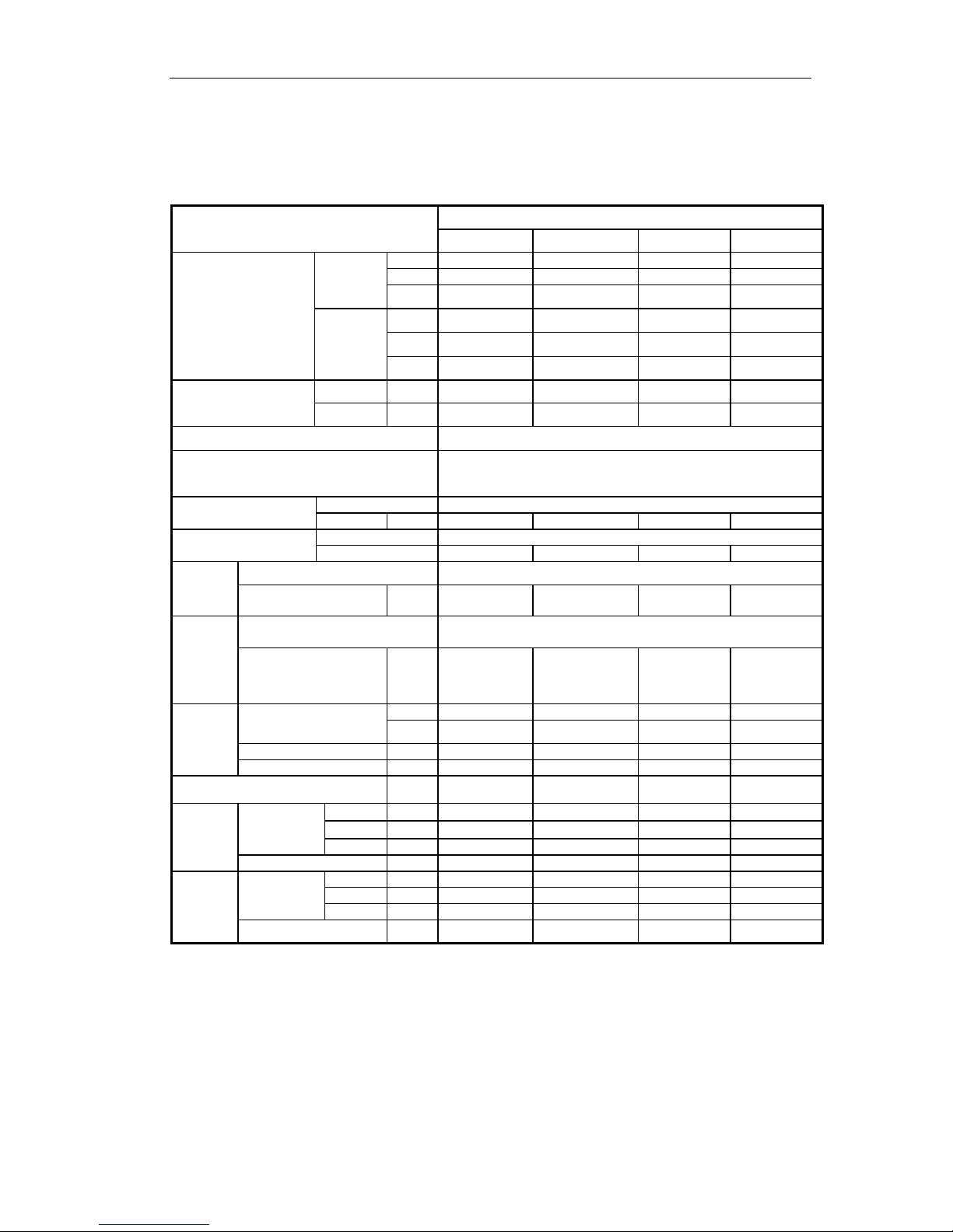
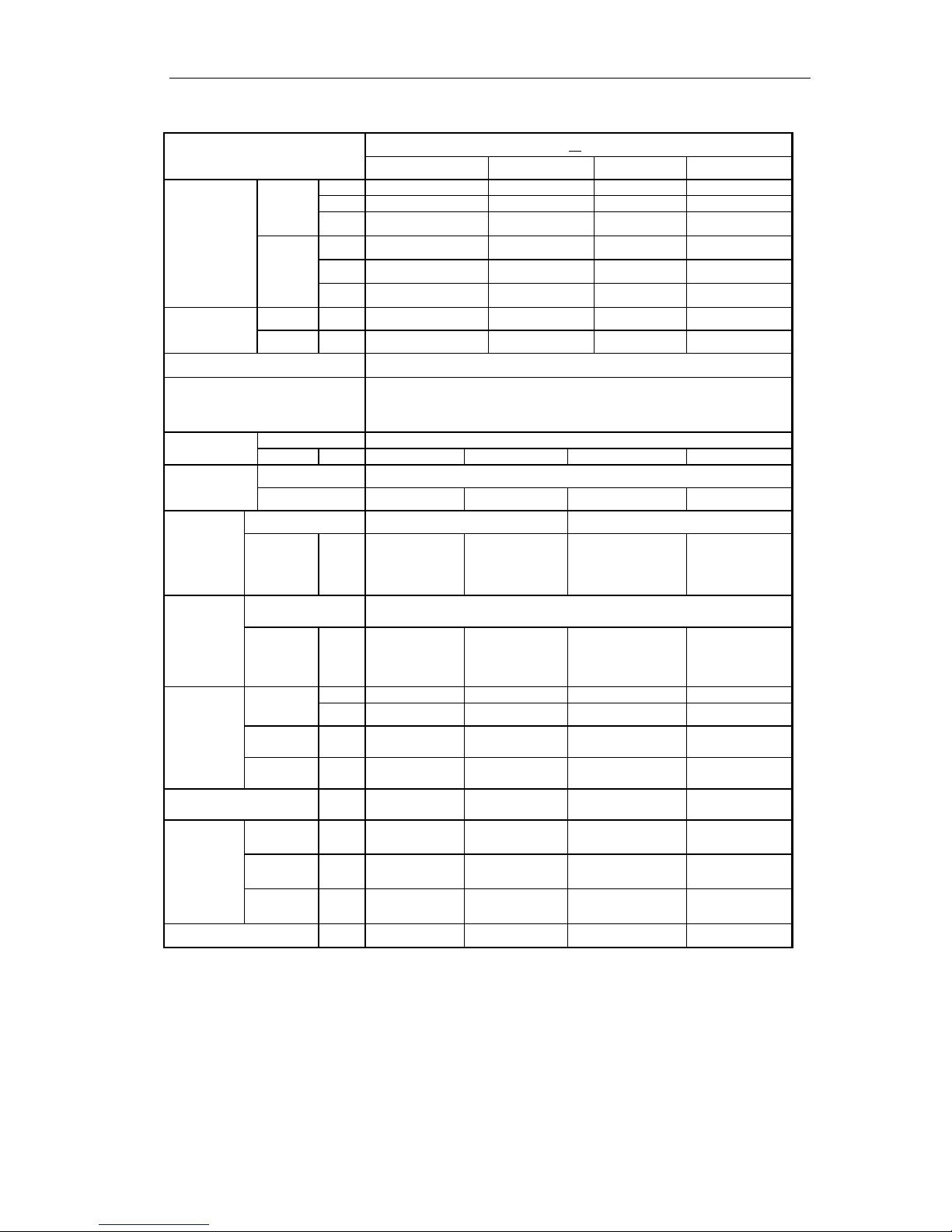
4 PRODUCT DATA
4.1 Product Data at Rated Condition
4.1.1 Split Type
Models
IMCR_WZNa-M
8 10 12.5 15
Nominal Capacity
Cooling
kW 8 10 13 15
Btu/h 27300 34120 42650 51180
RT 2.3 2.9 3.6 4.3
Heating
kW 9 11 15.5 16
Btu/h 307000 37550 44356 54600
RT 2.6 3.1 3.7 4.6
Power
Consumption
Cooling kW 3.3 4.4 5.2 5.6
Heating kW 3.2 4.2 5.0 5.5
Power Supply 380~415V,3Ph,50Hz
Safeties
High/Low pressure switch, compressor thermal protection, over
current protection, lose of phase/anti-phase protection,
antifreeze protection, water flow switch
Refrigerant
Type R4 10A
Charge kg 3.1 3.55 3.6 5.5
Compressor
Type scroll
NO. 1 1 1 1
Evaporator
Heat Exchanger Tube-in-Tube
Water In/Out Pipe
Diameter
Inch 1’ 1’ 1’ 1’
Condenser
Heat Exchanger Aluminum fin-copper tube
Fan Motor Power Input
kW 0.2 0.14 0.14 0.2
Pump
Water Flow
L/s 0.36 0.5 0.56 0.72
GPM 5.78 7.94 8.83 11.48
Delivery Lift m 18 18 18 18
Power Input kW 0.55 0.55 0.55 0.55
Expansion Vessel Volume L 5 5 5 5
Indoor
Unit
Unit /
Packing
Dimension
Height mm 288/385 288/385 288/385 288/385
Width mm 1100/1285 1100/1285 1100/1285 1100/1285
Depth mm 450/682 450/682 450/682 450/682
Net/Gross Weights 84/96 84/96 84/96 84/96
Outdoor
Unit
Unit /
Packing
Dimension
Height mm 840/985 1250/1385 1250/1385 1250/1385
Width mm 950/1100 950/1110 950/1110 1100/1260
Depth mm 412/450 412/450 412/450 412/450
Net / Gross Weights
90/100 112/123 115/126 123/134
MINI CHILLER PRODUCT
7
4.1.2 Integral Type
Models
IMCR
SNa-M
22 25 35 45
Nominal
Capacity
Cooling
kW 22 25 35 43
Btu/h 64828 85300 119420 153540
RT 5.4 7.1 10 13
Heating
kW 26 27 37 50
Btu/h 71650 92124 126250 184248
RT 6 7.7 10.6 15.4
Power
Consumption
Cooling kW 8.7 9.0 11.8 17.1
Heating kW 8.8 8.85 12.3 16.6
Power Supply 380~415V 3Ph 50Hz
Safeties
High/Low pressure switch, compressor thermal protection, over current
protection, lose of phase/anti-phase protection, antifreeze protection,
water flow switch
Refrigerant
Type R4 10A
Charge kg 3.6X2 4.8X2 6.5X2 7.3X2
Compressor
Type scroll
NO. 2 2 2 2
Evaporator
Heat Exchanger Tube-in-Tube Shell and tube
Water
In/Out
Pipe
Diameter
Inch 1’ 1’ 1-1/2’ 1-1/2’
Condenser
Heat Exchanger Aluminum fin-copper tube
Fan
Motor
Power
Input
kW 0.4 0.4 0.6 0.8
Pump
Water
Flow
L/s 0.9 1.2 1.4 2.2
GPM 14.5 18.9 22.9 35.2
Delivery
Lift
m 22 24 25 27
Power
Input
kW 0.75 0.75 1.5 1.5
Expansion Vessel
Volume
L 8 8 8 8
Unit / Packing
Dimension
Height mm 1850/1960 1850/1960 1760/1870 1761/1870
Width mm 1460/1540 1460/1540 1750/1830 1750/1830
Depth mm 530/610 530/610 800/880 800/880
Net/Gross Weights
kg
370/380 390/400 680/690 755/765
NOTE:
1、Cooling capacity is based on the following conditions:leaving chilled water temp.7℃,outdoor air temp.35℃
2、Heating capacity is based on the following conditions:leaving warmed water temp.45℃, outdoor air
temp.7℃
3、Water flow range for operation must be from 70% to 120% of the rated water flow。
4、The maximum allowable pressure for water pipe is 0.9MPa
MINI CHILLER PRODUCT
8
4.2 Operation Range
Mode
Range of Outdoor Temperature℃ (℉)
Cooling 16~48
Heating -15~28
4.3 Pressure-loss Conversion Chart
Water F l o w (m3/h) 1.2 1.4 1.7
1.9 2.0
The percentage (%) 70 80 100 110 120
Loss of Pressure (kPa) 200 100 0
100 200
NOTE:
The percentage is contrasted to nominal water flow.
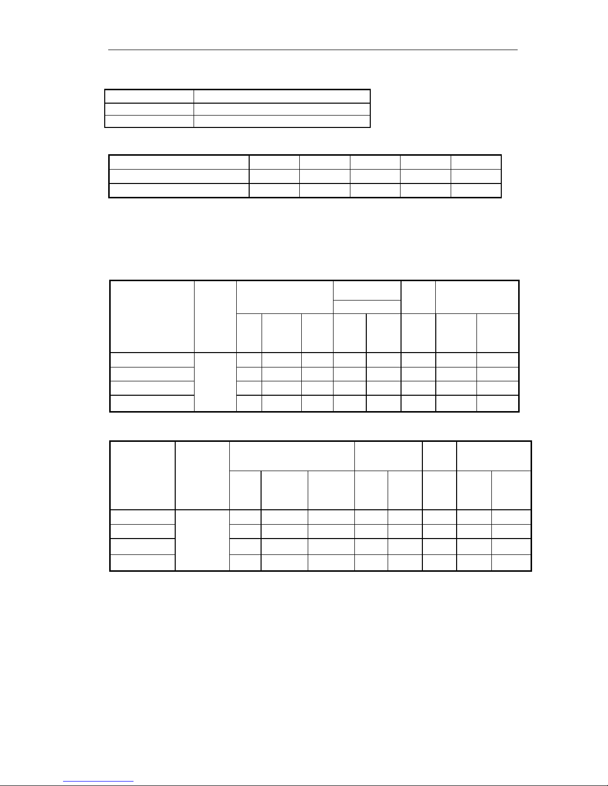
4.4 Electrical Data
4.4
.1 Split Type
Model
Rated
Power
Supply
Compressor
Fan Motor
Pump Total
Outdoor
NO.
LRA
each
(A)
MRC
each
(A)
NO.
MRC
(A)
MRC
(A)
MRC
(A)
NRC
(A)
IMCR8WZNa-M
380~41
5V 3Ph
50Hz
1 97 21.2 1 1.5 1.0 23.4 17
IMCR10WZNa-M
2 49 13.2 2 2 1.0 31 22
IMCR12.5WZNa-M
2 52 16.1 2 3 1.0 39 28
IMCR15WZNa-M
2 69 17 2 3 1.0 47 33.5
4.4.2 Integral Type
Model
Rated
Power
Supply
Compressor Fan Motor Pump Total
NO.
LRA
each
(A)
MRC
each
(A)
NO.
MRC
(A)
MRC
(A)
MRC
(A)
NRC
(A)
IMCR22SNa-M
380~415V
3Ph 50Hz
2 42 9.5 2 5 1.3 19.5 14
IMCR25SNa-M`
2 56 11.2 2 5 1.3 23.5 16.8
IMCR35SNa-M
2 101 15.3 2 7.5 2.7 42 30
IMCR45SNa-M
2 110 21.4 2 7.5 2.7 54 38.5
Notes:
LRA: Locked rotor amps (A)
MRC: Maximum running current (A)
NRC: Nominal running current (A)
MINI CHILLER PRODUCT
9
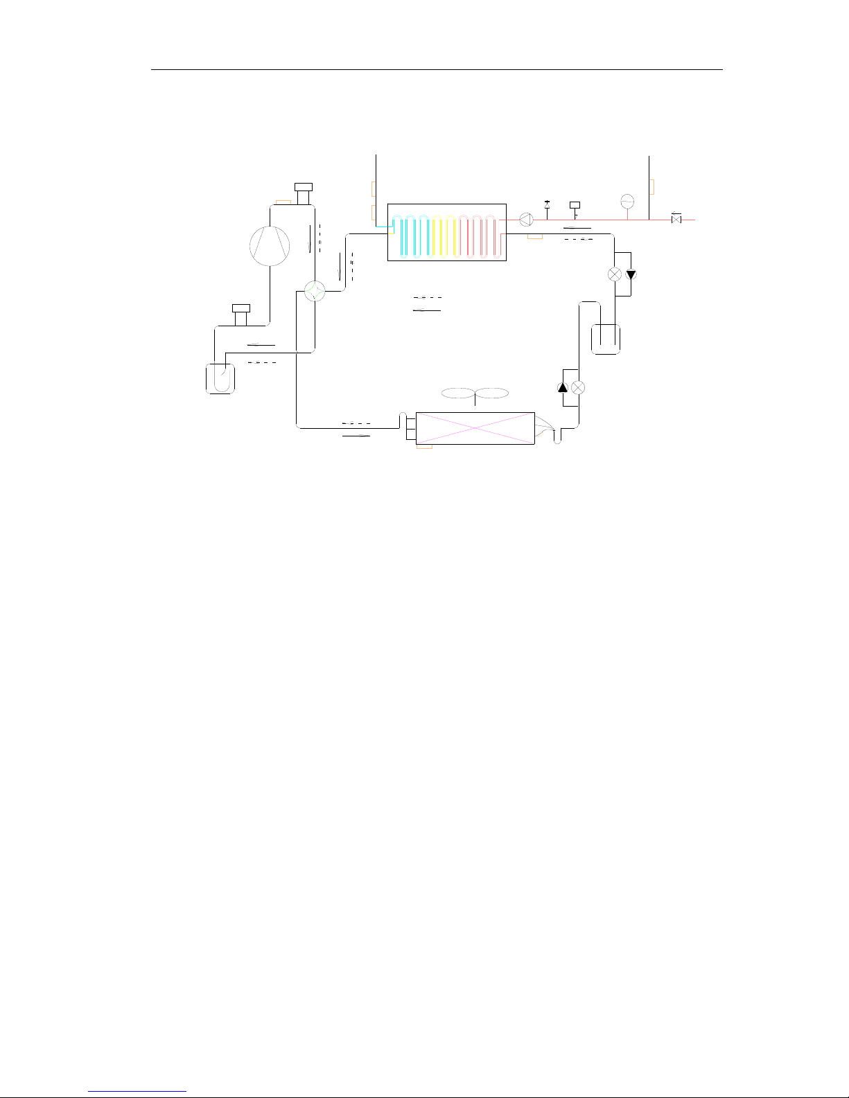
5 PIPING DIAGRAM
Heating circuit
Cooling circuit
Pump
Relief
valve
Flow
switch
Expansion
drum
High pressure
tank
Aluminum fin-copper tube
coil
Four-way valve
Shell and tube heat
exchanger
Inlet
Outlet
High-pressure
switch
Compressor
Low-pressure
switch
Liquid-gas separator
F

INVENTOR COMMERCIAL AIR CONDITIONERS MINI
CHILLER
10
CONTROL
MINI CHILLER CONTROL
11
UNITS CONTROL
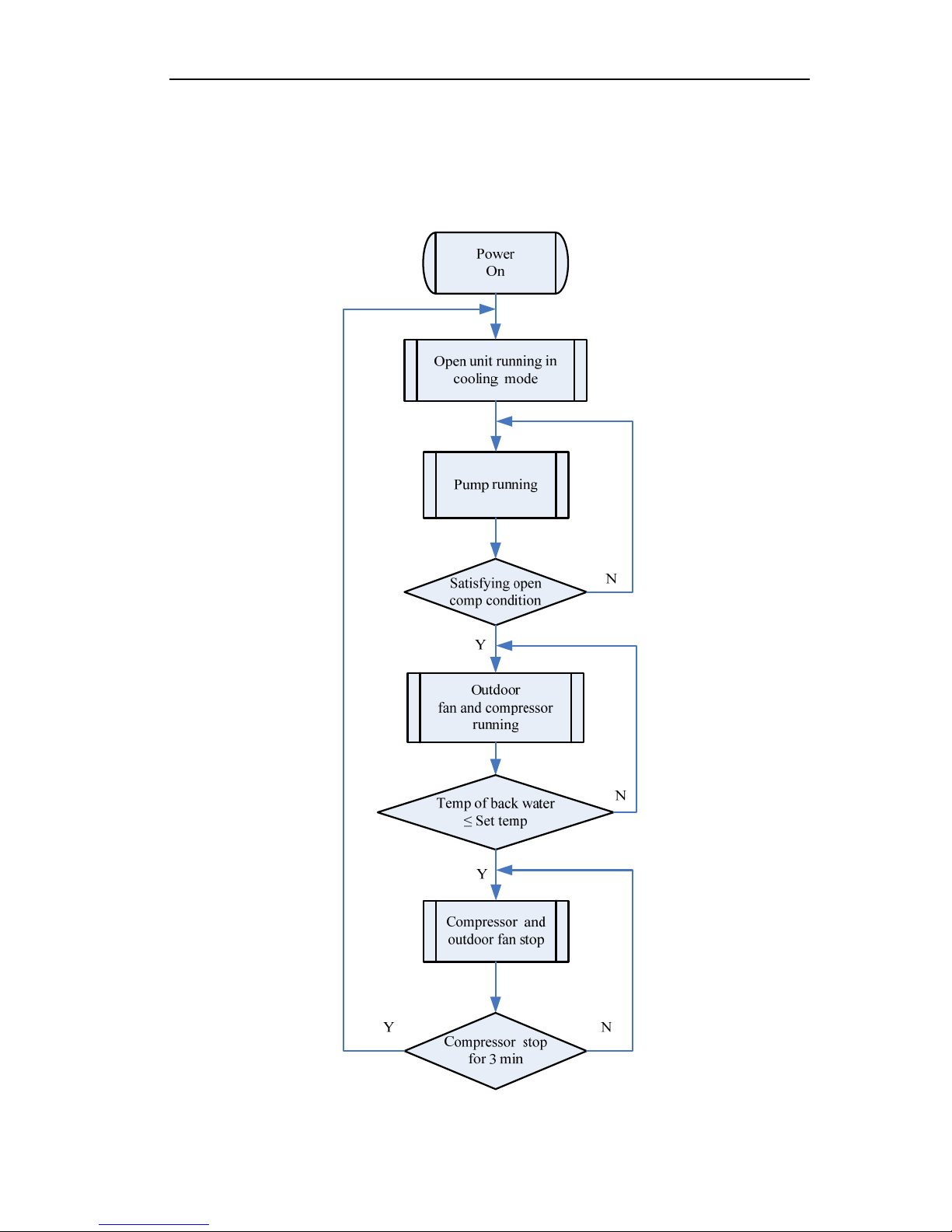
1 OPERATION FLOWCHART
1.1 Cooling Operation
MINI CHILLER CONTROL
12
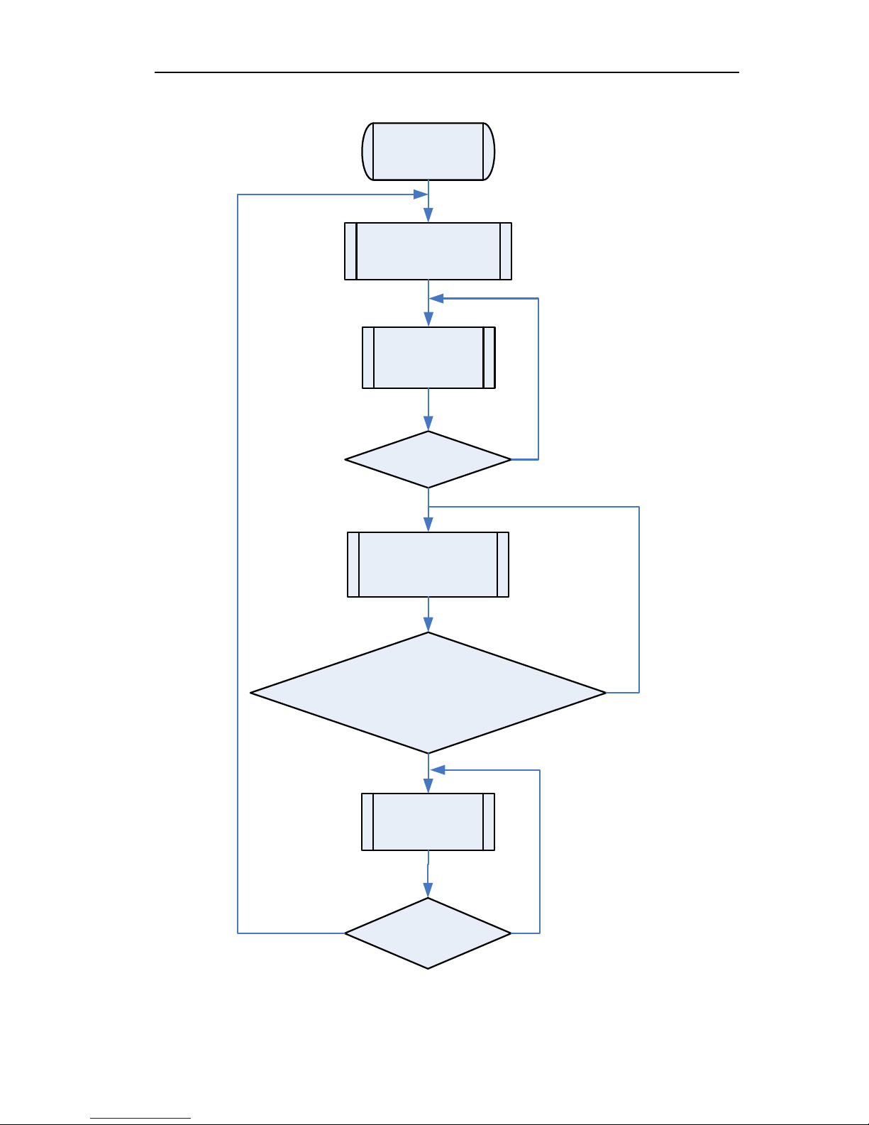
1.2 Heating Operation
Power
On
Open unit running in
heating mode
Satisfying open
comp condition
Pump running
Outdoor
fan, compressor and
valve running
Temp of back water
≥ (Set temp + 5) (spilt type)
Temp of back water
≥ (Set temp + 6) (Integral type)
Compressor and
outdoor fan stop
Compressor stop
for 3 min
NY
N
Y
Y
N
MINI CHILLER CONTROL
13
2 MAIN LOGIC
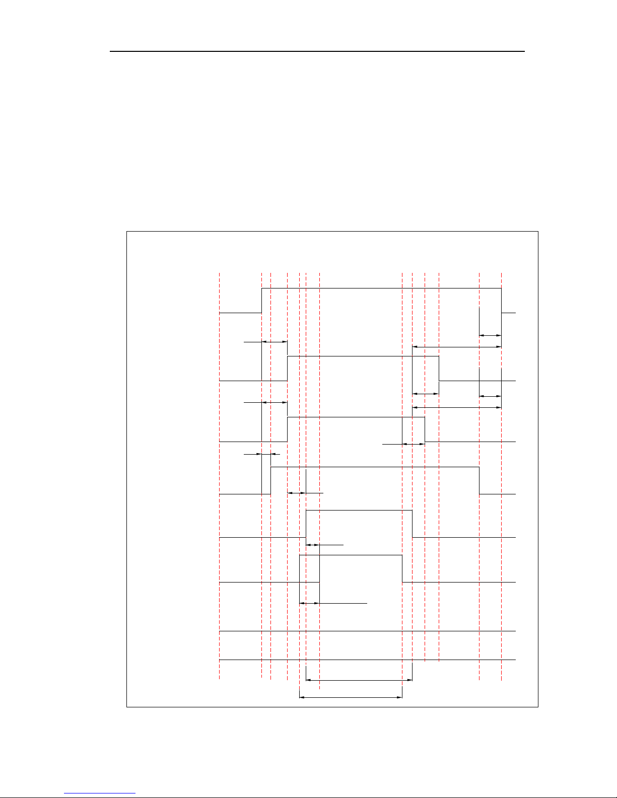
2.1 Cooling Mode
When press ON button, if the outdoor temperature is over 16℃, it starts the water pump first After
30s, if the outlet water temperature meets the cooling running requirements, it starts the fans of outdoor
unit. Then the compressor will run after 15s. During the period of cooling, the unit will turn off if the
outlet water temperature meets the stopping requirements and the running time of compressor is over
the shortest running time required. The fans of outdoor unit will stop after 15s.
If the outdoor temperature is below 16℃, the unit will stop, and turn off all loads except the water
pump.
Turn on
Turn off
Pump
1
Fan 1
Fan 2
Flow Switch
Compr essor
1
Compr ess or 2
Four-way valve 1
Four-way valve 2
30S
30S
5S
15S
10min
15>Tout>12
14>Tout>7
15>Tout>8
Check if flow switch is ok
15S
15S
5S
3min
3min
5S
When it is turned off
When it is turned off
MINI CHILLER CONTROL
14
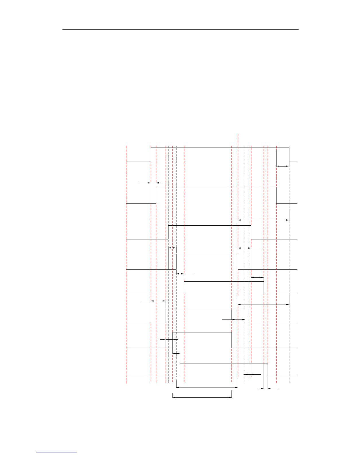
2.2 Heating Mode
When press ON button, if the outdoor temperature is below 28℃, it starts the water pump first After
30s, if the outlet water temperature meets the heating running requirements, it starts the fans of outdoor
unit. Then the compressor will run after 15s. During the period of cooling, the unit will turn off if the
outlet water temperature meets the stopping requirements and the running time of compressor is over
the shortest running time required. The fans of outdoor unit will stop after 15s.
If the outdoor temperature is over 28℃, the unit will stop, and turn off all loads except the water
pump.
Pump
Turn
off
Turn
on
Flow Switch
Fan 1
Compressor 1
Four-way Valve1
Fan 2
Compressor 2
Four-way Valve 2
15S
Check if flow switch is ok
5S
3min
When it is turned off
15S
30S
3min
When it is turned off
5S
15S
30S
5S
15S
2S
5S
15S
48<Tout<54
46<Tout<52
MINI CHILLER CONTROL
15
2.3 Defrosting Mode
The condition of start defrosting mode:
Under heating mode, if the accumulative running time of compressor is over the set interval time
of defrosting( default 45min),and the defrosting temperature is lower than the set starting
temperature(default -4℃) ,the unit will start running defrosting mode, and the 4-way valve will shut
off and the outdoor fan will stop after 2s.
The condition of quit defrosting mode:
Under defrosting mode, if the continual defrosting time is over the set continual time of defrosting
(default 8min),and the defrosting temperature is over the set stopping temperature(default 20℃) ,the
unit will restart running heating mode, and the 4-way valve will turn on and the outdoor fan will run.
3 WIRED CONTROLLER
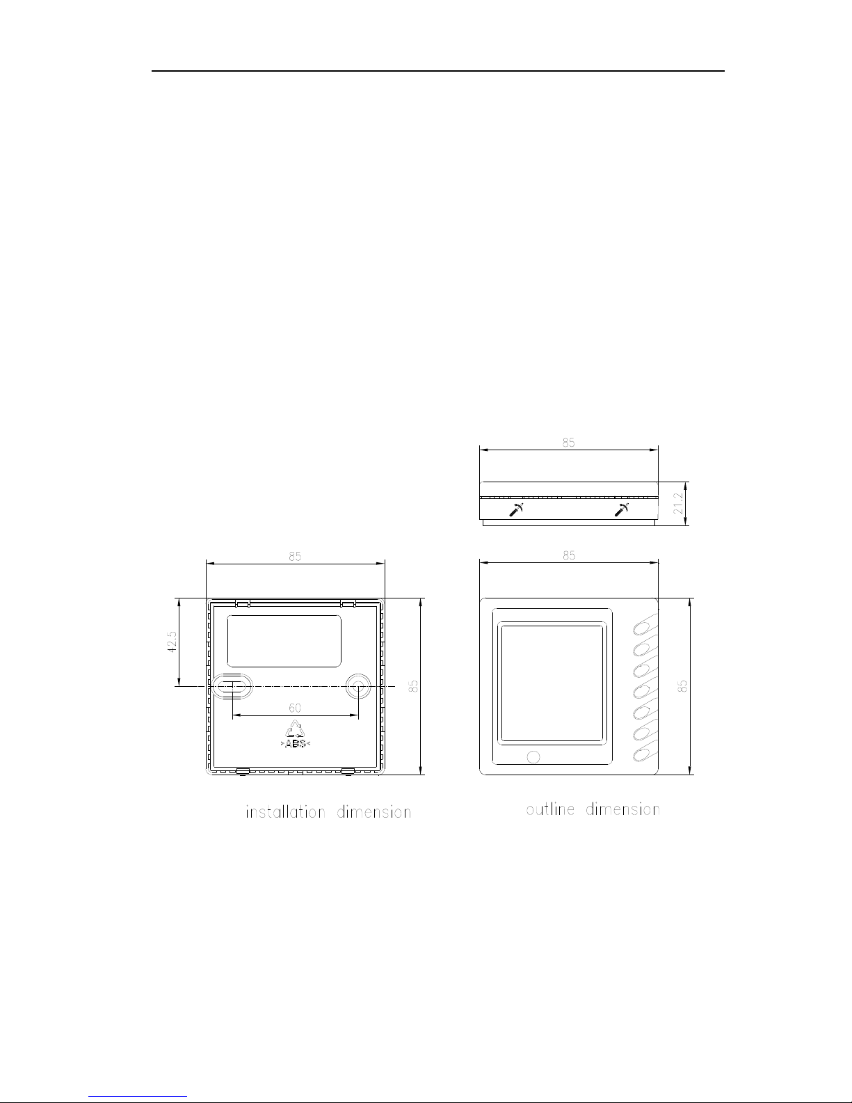
3.1 Dimension
3.2 Function
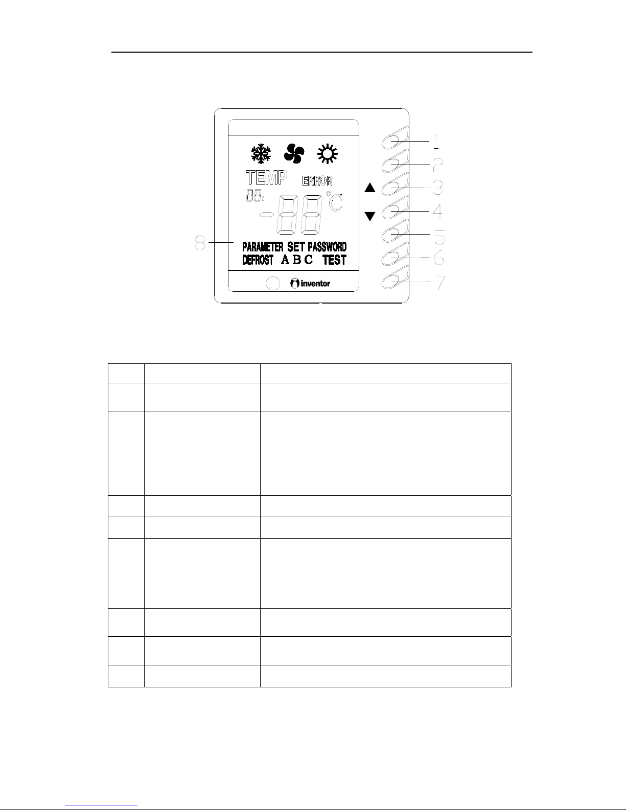
3.2.1 Operation View
MINI CHILLER CONTROL
16
MODE
CHECK
ON
QUIT
OFF
NO. Name Function description
1 MODE button
It can switch between cooling and heating, this button is
available only on cooling and heating unit.
2 CHECK button
Press it once under normal state to enter check mode,
under check mode, press this button when “17” is
displayed can change the value of “17”. Under parameter
set mode, press this once can switch the adjusting objection
between parameter and value, press this button for long
(about 5s) to save and quit this parameter setting.
3 Increasing button
To increase present set value or change set/check object.
4 Decreasing button
To decrease present set value or change set/check object.
5 QUIT button
Under Set and Check mode, press it once to quit this mode.
Under parameter set mode, this set value would not be
saved. Press this button for long (about 5s) to set sound,
and make sound switches between always on and always
off.
6 ON button
To turn on the unit; when under compel operation, press
once to quit compel operation.
7 OFF button
To turn off the unit; press it once to quit compel operation
when the unit is under compel operation.
8 LCD display Display information of the unit.
Note:
(1) Turn On, Off Auxiliary Heater: It is only available for heat pump unit. Press CHECK once to
MINI CHILLER CONTROL
17
enter Check mode. Press ▲ and ▼ to change check object, press CHECK again till the present
check object becomes “17”, value “17” switches between 01/03 (auxiliary heater on) and 00/02
(auxiliary heater off). That is 00 Off —>01 On —>00 Off, or 02 Off —>03 On —>02 Off.
(2) Check Parameter: After electrify for 20s, press QUIT then ▲ to enter parameter checking mode.
Under this mode, Auxiliary display area shows the checking object, Main display area displays
the value for the checking object. Press ▲ and ▼ to change the checking object. Press QUIT to
quit from the check mode.
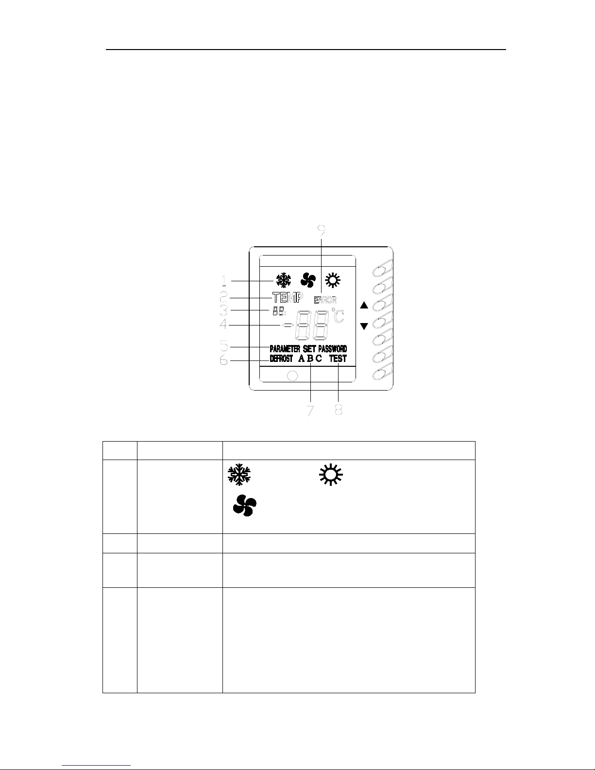
3.2.2 Display View
OFF
QUIT
ON
CHECK
MODE
NO. Name Function description
1 Running mode display
: cooling mode, : heating mode,
: reserved
2 Temp display It shows temperature value displays at main display area.
3 Auxiliary display area
It contains 2 numbers and a comma, for showing temperature and
number of parameter at main display area. It only displays when under
Check mode and Parameter checking mode.
4 Main display area
It contains a minus, 2 numbers and 1 temperature unit, for displaying
value of temperature and parameter (temperature or time value) and error
code. When temperature value is displayed, it shows value in algorism
and temperature unit; when time is displayed, it shows algorism value but
no temperature unit (default unit is min); when it is code, it displays
specific error (refer to Malfunction Error List) but no temperature unit.
Individual temperature or parameter may exceed 99, then adopt AX for
100~109, bX for 110~119, CX for 120~129, dX for 130~139, EX for
140~149, FX for 150~159, and X stands for a number between 0~9.

MINI CHILLER CONTROL
18
Under normal state, it shows temperature for back water.
5 Parameter display
It means the value shown at present main display area is parameter. It
shows only under Parameter Check mode.
6 Defrost display It displays when defrosting, otherwise it doesn’t displays.
7 System ID
It displays when system or compressor orders, for showing which system
is defrosting.
8 Testing display For testing, it displays under compel operation.
9 Error code display
It shows the error code displayed on Main Display Area. It displays when
there is error at system or communication.
Caution:
(1) When unit is off, it displays only temperature of back water. When unit is on, under normal state,
if there is no error, it displays temperature of back water, if there is error, it displays error code;
when there is no operation after 60s of pressing the button, it quit back to normal state display
automatically.
(2) Auto antifreeze operation display (only for heat pump unit)
When auto antifreeze function is started and relevant conditions are satisfied, unit begins auto
antifreeze operation. At this time, LCD main display area displays code d2 (if there is error it
displays error code).
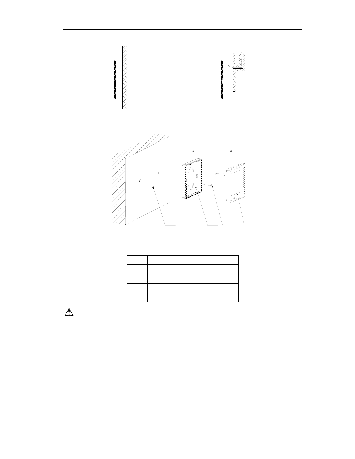
3.3 Installation
1. First select an installation position. According to the size of the communication line of the wire
controller, leave a recess or a embedded wire hole to bury the communication line.
2. If the communication line between the wire controller (85×85×20) and the indoor unit is
surface-mounted, use 1# PVC pipe and make matching recess in the wall (refer to Figure 6); If
concealed installation is adopted, 1# PVC pipe can be used (Refer to Figure 7).
3. No matter if surface mounting or concealed mounting is selected, it is required to drill 2 holes (in
the same level) which distance shall be the same as the distance (60mm) of installation holes in
the bottom plate of the wire controller. Then insert a wood plug into each hole. Fix the bottom
plate of the wire controller to the wall by using the two holes. Plug the communication line onto
the control panel. Lastly install the panel of the wire controller.
Caution:
During the installation of the bottom plate of the wire controller, pay attention to the direction of
the bottom plate. The plate’s side with two notches must be at the lower position, and otherwise the
panel of the wire controller cannot be correctly installed.
MINI CHILLER CONTROL
19
PVC pipe
Fig6:Surface Mounting of Cable Fig7:Concealed mounting of Cable
1 324
Fig 8 Schematic Diagram of Installation
No. Name
1 Wall Surface
2 Bottom Plate of Wire Controller
3 Screw M4X10
4 Panel of Wire Controller
Caution:
1. The communication distance between the main board and the wire controller can be as far as 20m
(The standard distance is 8m).
2. The wire controller shall not be installed in a place where there is water drop or large amount of
water vapor.
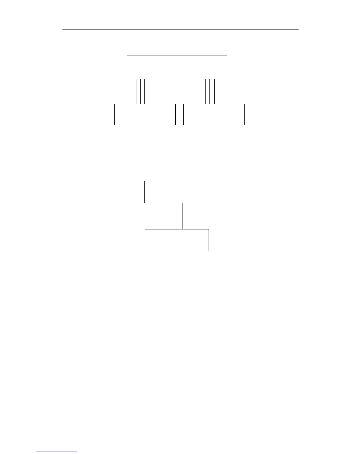
4 CONTROL WIRING DESIGN
MINI CHILLER CONTROL
20
twisted-pair
twisted-pair
X17J1
CN2
CN1
Outdoor Unit Controller
Manual Unit Controller
Indoor Unit Controller
The controllers of the split type unit include manual controller, indoor unit controller and outdoor
unit controller. The indoor unit controller communications with manual controller and outdoor unit
controller in RS485. The indoor unit controller connects manual controller with 4-line twisted-pair.
Similarly, the indoor unit controller connects outdoor unit controller with 4-line twisted-pair.
Indoor Unit Controller
Manual Unit Controller
Outdoor Unit Controller
J1
X17
twisted-pair
The controllers of the Integral type unit include manual controller and outdoor unit controller. The
manual controller communications with outdoor unit controller in RS485. The manual controller
connects outdoor unit controller with 4-line twisted-pair.

INVENTOR COMMERCIAL AIR CONDITIONERS MINI
CHILLER
21
INSTALLATION

MINI CHILLER INSTALLATION
22
UNITS INSTALLATION
1 UNITS INSTALL
1.1 Installation Positions
For indoor unit:
z Fix the indoor unit bracket to the wall using appropriate plugs and screws.
z Hang the indoor unit on the top wall mounting bracket.
z Fix the indoor unit at the bottom side using appropriate plugs and screws.
For outdoor unit:
z The installation is frost-free.
z The space around the unit is adequate for servicing.
z The space around the unit allows for sufficient air circulation.
z There is no danger of fire due to leakage of flammable gas.
z All piping lengths and distances have been taken into consideration.
1.2 Matters need Attention
z The
indoor unit is packed in a cardboard box, fixed by straps.
z At delivery, the unit should be checked and any demage should be reported immediately to the
carrier claims agent.
z Check if all indoor unit accessories are enclosed.
z The indoor unit is heavy and should be lifted by two persons.
1.3 DIMENSION DATA
z Split
type
IMCR8WZNa-M(O)
950 340
840
378
412572

MINI CHILLER INSTALLATION
23
IMCR10WZNa-M(O),IMCR12.5WZNa-M(O)
IMCR15WZNa-M(O)

MINI CHILLER INSTALLATION
24
IMCR8WZNa-M(I), IMCR10WZNa-M(I) , IMCR 12.5WZNa-M(I) and IMCR15WZNa-M(I)
Unit: mm
572
450
512
1100
288
z Integral Type
IMCR22SNa-M、IMCR25Na-M
G1"
1850
1460
1260
530
544
G1/2"
G1"
inlet
outlet
DN12mm
Water-filled
vavle
IMCR35Na-M、IMCR45Na-M

MINI CHILLER INSTALLATION
25
7101290
G1-1/2"
1750
1760
800
G1-1/2"
直径12mm
Water Inlet
Water Outlet
1.2 INSTALLATION CLEARANCE DATA
z Split
type(Outdoor unit)
L3
L2
L4
L1
air inlet
air outlet
unit:mm
demonstration L1 L2 L3 L4
distance >500 >1000 >500 >500
z Split type(Indoor unit)

MINI CHILLER INSTALLATION
26
L3
L2
L1
Seismic Spring
Isolators
unit:mm
demonstration L1 L2 L3
distance >250 >800 >1200
Integral Type

MINI CHILLER INSTALLATION
27
air outlet
1290(foundation bolt4-M12)
1750
>1000
>300
>1000
foundation bolt
base
rubber isolator
concrete base
>1200
>1000
1750X2+300=3800
water
outlet
>2000
unit mm
air outlet
water
inlet
water
outlet
water
inlet
air inlet
air inlet
air inlet
air inlet
air inlet
air inlet
air inlet
air inlet
lift method: Cable through the hole, lift by hook

MINI CHILLER INSTALLATION
28
2 WATER PIPING WORK
2.1 Installation Procedure
For all guidelines, instructions and specifications regarding refrigerant pipework between the indoor
unit and the outdoor unit. Please refer to the outdoor unit installation manual.
The units are equipped with a water inlet and water outlet for connection to a water circuit must be
provided by a licensed technician and must comply with all relevant national regulations.
2.2 Matters of Attention
A
ir vents must be provided at all high points of the system. The vents should be located at points which
are easily accessible for servicing. An automatic air purge should be used. Check the valve is not
tightened too much so that automatic release of air in the water circuit remains possible.
2.3 Antifreeze
%
by Weight
0 12 22 30 36 41
Freezing Point℃(℉)
0(32) -5(23) -10(14) -15(5) -20(-4) -30(-22)
Ambient Temperature ℃
(℉)
8.3(47) 3.3(38) -1.7(29) -6.7(20) -11.7(11) -16.7(2)
Cooling Capacity
Correction Factor
1.0 0.985 0.980 0.974 0.970 0.965
Water Flow Correction
Factor
1.0 1.02 1.04 1.075 1.11 1.14
Pressure Drop Correction
Factor
1.0 1.07 1.11 1.18 1.22 1.24
3 ELECTRIC WIRING WORK
3.1 Wiring Principle
POWER SUPPLY — The electrical characteristics of the available power supply must agree with the
unit nameplate rating. Supply voltage must be within the limits shown. See 3.3 for electrical and
configuration data. FIELD POWER CONNECTIONS — All power wiring must comply with
applicable local and national codes. Install field-supplied, branch circuit fused disconnect(s) of a type
that can be locked off or open. Disconnect(s) must be located within sight and readily accessible.
3.2 Electric Wiring Design
3.2
.1 Electric Wiring Design- Split Type
3.2.2 Electric Wiring Design- Integral Type
3.3 SPECIFICATION OF POWER CORD & AIR SWITCH
Mod
el Power Supply
Capability
of Air
Switch(A)
Minimum
Sectional Area
of Earth
Wire(mm
2
)
Minimum
Sectional Area
of Power
Cord(mm2)
IMCR8WZNa-M
380~415V,3,50
10 2.5 2.5
IMCR10WZNa-M
380~415V,3,50
13 2.5 2.5

MINI CHILLER INSTALLATION
29
IMCR12.5WZNa-M
380~415V,3,50
16 2.5 2.5
IMCR15WZNa-M
380~415V,3,50
16 2.5 2.5
IMCR22SNa-M
380~415V,3,50
25 4 4
IMCR25SNa-M
380~415V,3,50
32 6 6
IMCR35SNa-M
380~415V,3,50
63 10 10
IMCR45SNa-M
380~415V,3,50
63 10 10
Note:
3.4 WIRING DIAGRAM
3.4.1 Wiring Diagram-Split Type
3.4.1.1 Outdoor Units
Model:IMCR8WZNa-M
WH
RD
BU
BU
C2
KM
TC
C1
XT3
AP1
XT1
XT2
WH
BN
BN
BU
BK
TC
BN
W22
BU
W21
W20
RD
EH
2
1
W19
RD
W17
RD
W18
BN
W16
BN
W15
W14
BK
W13YEW12
W11
WH
W10
RD
W9
W8
WH
W7
WH
W6
BU
W5
BUW4
BU
W3
2
1
2
1
X7
RD
W2
W1
Electric heater
C2
C1
Άτ
Άσ
Άς
Άρ
PE
Fan motor
compressor
PE
E
YEGN
YEGN
E
PE
AP2
indoor
unit
1
0
2
1
XT3
6
415
3
1
2
XT2
KM
2
86
4
S
R
C
L
N
COMP
M
Model: IMCR10WZNa-M, IMCR12.5WZNa-M

MINI CHILLER INSTALLATION
30
POWER
XT3
AP1
C1C2
XT1
KM2
KM1
TC
XT2
C3C4
COMPONENT POSITION
DIAGRAM
12
2
1
1
2
2
1
W56
W52
W51
W50
W49
W48W47
W45
W43
W42
X34
X33
X32
X31
W38
W37
W36
W35
W34
W33
W32
W27
W31
W30
W29
W28
X10X9
X8X7
YE
BUBNWH
BK
BN
BN
BKWHBNBU
YE
C4
C3
compressor1
Fan motor 1
2
1
2
1
2
1
KM2
6
4
1
5
3
6
4
1
5
3
PE
E
YEGN
M2
3
5
1
4
6
2
2
6
4
1
5
3
L1
T1
KM2
KM1
T1
L1
C1
YEGN
E
PE
S
R
C
COMP1
M1
COMP2
XT1
N
L
C
R
S
KM1
XT2
2
1
XT3
1
2
indoor
unit
AP2
PE
E
YEGN
YEGN
E
PE
compressor2
Fan motor 2
PE
Άρ
Άς
Άσ
Άτ
C2
1
2
W24
TC
Model: IMCR15WZNa-M
W37
W34
W33
W49
W50
W38
W36
W35
W52W51
W27
W32
W31
W30
W28
W29
63622212
3.4.1.2 Indoor Units

MINI CHILLER INSTALLATION
31
OG
controller
COMPONENT POSITION
DIAGRAM
pump
M
PE
PE
Temp.Sensor
Temp.Sensor
Temp.Sensor
Frost-proof
KM1
KM2
TC
XT1
AP2
TC
flow in
CN4
CN13
CN6
flow out
AP2
anti-ice1
X1
AP3
4
CN2
CN1
CN11
OVERLOAD
CN12
OUTDOOR UNIT
12WH
10BK
X17
11BK
AP1
FL
W_FLOW
+12V
CN5
YEGN
16
W1
U1
W2
T1
6YE
KM2
L1
4BU
L
N
1BN
7BU
XT1
PE
POWER
NN
L
L
2RD
KM2KM1
end_switchheat1
pump
HEATER
A2
A2
EH
13OG
14GN
T1
L1
A1
A1
KM1
9BU
5RD
8BU
3YE
XT1-2
XT1-1
HT
15
Water-Outlet
Water-Inlet
3.4.2 Wiring Diagram- Integral Type
M
odel:IMCR22SNa-M, IMCR25SNa-M,

MINI CHILLER INSTALLATION
32
Specification:
1.Auxiliary electric heater is optional part for heat pump unit, once it is used, please connect the temp. restricter HT1
with XT2.1-1 and XT2.1-2.
2. Cooling only type unit do not have below parts: KM5, Auxiliary electric heater, LP12, LP22, Defrost temp. sensor 1.
. if the chiller is connected with fancoil units, please remove the wire between AC-L and X16 on PC, then connect X16
to X1 on fancoil unit patching board.
. Remarks: " " means terminals on XT2.1 or XT2.2 patching board.
723
724
3 3
3
33
M1
M2
M3
PEEPE PE PE PE
EEEE
PE
Άρ
ΆςΆσ
R
S
T
Άρ
Άς
Άσ
TC
11
IMCR35SNa-M, IMCR45SNa-M
M1
M2
M3
EEE EE
Specification:
Auxiliary electric heater is optional part for heat pump unit, once it is used, please connect the temp. restricter HT1
with XT2-10 and XT2-11.
2. Cooling only type unit do not have below parts: KM5, Auxiliary electric heater, LP12, LP22, RT5
,RT6,YV1,YV2.
3. if the chiller is connected with fancoil units, please remove the wire between AC-L and X16 on PC, then connect X16
to X1 on fancoil unit patching board.
4. Remarks: " " means terminals on XT2 patching board.

INVENTOR COMMERCIAL AIR CONDITIONERS MINI
CHILLER
33
MAINTENANCE

MINI CHILLER MAINTENANCE
34
UNITS MAINTENANCE
1 ERROR CODE LIST
Code Indication Error Name Control Description
E1
Comp. 1 High-pressure
protection
Press ON/OFF key to clear
E2
System 1 antifreeze
protection
Auto resume
E3
Comp. 1 Low pressure
protection
Press ON/OFF key to clear
E4
Comp. 1 Discharge temp.
protection
Press ON/OFF key to clear
E5
Comp. 1 overload
protection
Press ON/OFF key to clear
E6 Pump overload protection Press ON/OFF key to clear
E7 Flow switch failure Press ON/OFF key to clear
E8 Fan 1 overload protection Press ON/OFF key to clear
E9
System 1 outlet water
temp. too high
Auto resume
b1
Comp. 2 High-pressure
protection
Press ON/OFF key to clear
b2
System 2 antifreeze
protection
Auto resume
b3
Comp. 2 Low pressure
protection
Press ON/OFF key to clear
b4
Comp. 2 Discharge temp.
protection
Press ON/OFF key to clear
b5
Comp. 2 overload
protection
Press ON/OFF key to clear
b8 Fan 2 overload protection Press ON/OFF key to clear
b9
System 2 outlet water
temp. too high
Auto resume
F1
Antifreeze temp. sensor 1
failure
Auto resume
F2
Antifreeze temp. sensor 2
failure
Auto resume
F3
Defrost temp. sensor 1
failure
Auto resume
F4
Defrost temp. sensor 2
failure
Auto resume
F5
Discharge temp. sensor 1
error
Auto resume
F6
Discharge temp. sensor 2
error
Auto resume
F7
Outdoor ambient temp.
sensor failure
Auto resume
F8
Inlet water temp. sensor
failure
Auto resume
F9
Outlet water temp. sensor
failure
Auto resume
EC
Communication
malfunction
Auto resume
2 FLOW CHART OF TROUBLESHOOTING

MINI CHILLER MAINTENANCE
35
The unit cannot
start
If the power
supply is normal
Power off Stop and restart
If fuse burnt Replace the fuse
If three-phase
unit
If phase
sequence
protection
Adjust any two
phases
If the power of
mainboard is
failure
If the power
cable is fallen
Cut off the power,
restart after the power
is resumed
Mainboard is
broken
Replace the
mainboard
If the fuse is
burnt
Replace the fuse
The connection wire
between display board and
mainboard is loosened
Yes
Yes
No
Yes
No
No
Yes Yes
No
Yes
No Yes
Yes
No
Yes
No
Reconnect
Yes
If the
transformer is
burnt
No
Replace the
transformer
Yes
If The display
board is broken
No
Replace the
display board
No

MINI CHILLER MAINTENANCE
36
3 DISASSEMBLY AND ASSEMBLY PROCEDURE OF MAIN PARTS
3.1 Split Type
3.1.1 Outdoor Unit

MINI CHILLER MAINTENANCE
37
Operation Procedure Illustration
(1) Remove the front case
1) Remove the panel
· Loosen the two tappong screws
fixing the front grill.
·Pull down and remove the front grill.
(See Fig. 2)
2) Remove the cover.
· Loosen the two tappong screws
fixing the cover. Remove the cover
(See Fig. 3)
Fig. 1
Fig. 2
Fig. 3

MINI CHILLER MAINTENANCE
38
3)Remove the front plate.
· Loosen the two tappong screws
fixing the front plate. Remove the
front plate.(See Fig. 5)
4)Remove the grill
· Loosen the two tappong screws
fixing the grill. Remove the grill.
(See Fig. 6)
grill
Fig. 4
Fig. 5
Fig. 6

MINI CHILLER MAINTENANCE
39
(2) Remove the axial fan
· Loosen the ball nuts fixing the
axial fan and remove the washer.(See
Fig. 7)
·Pull outward to remove the impeller.
(See Fig. 7)
(3) Remove the motor
· Loosen the screws fixing the
motor support. Remove the motor
support.(See Fig .8 & Fig.9)
Ball Nut
Fig. 7
Motor support
Fig. 8
Fig. 9

MINI CHILLER MAINTENANCE
40
· Loosen the two screws fixing the
motor. Pull backward and remove the
motor.(See Fig .10)
·Loosen the wire of motor, and pull it
through the hole.
(4) Remove the 4-way valve and
capillary tube
1)Remove the 4-way valve
·Loosen the screws fixing the coil of
4-way valve。
·Remove the coil of 4-way valve。
·Welding out the tubes connected to the
4-way valve.
·Remove the 4-way valve.(See Fig.11)
Note:When welding, the valve should
be covered by wet cloth in order
to avoid the high temp. hurt。
2)Remove the capillary tube
·Welding out the tubes connected to the
capillary tube.
·Remove the capillary(See Fig.12)
Fig. 10
Fig. 11
Fig. 12

MINI CHILLER MAINTENANCE
41
(5) Remove electric box
· Loosen the screws fixing the box
cover. Remove all pressure
switches and temp. sensor.(See
Fig.13)
(6)Remove compressor and
gas-liquid separator
· Remove the connection wire of
compressor。(See Fig.14)
· welding out the suction pipe and
discharge pipe.(See Fig.14)
·Loosen the bolts fixing the compressor
and Remove the compressor and
gas-liquid separator.
Noise-absorbing cover
Fig.13
Gas-liquid separator Compressor
Fig.14

MINI CHILLER MAINTENANCE
42
(7)Remove gas and
liquid valve
1. Remove gas valve
·Loosen the bolts fixing the
gas valve.
· welding out the pipe
connected to the gas valve
(See Fig.15)。
Note : When welding, the
valve should be covered by
wet cloth in order to avoid
the high temp. hurt。
2. Remove liquid valve
·Loosen the bolts fixing
the liquid valve.
· welding out the pipe
connected to the liquid
valve (See Fig.16)。
Note : When welding, the
valve should be covered by
wet cloth in order to avoid
the high temp. hurt。
Fig.15
Fig.16

MINI CHILLER MAINTENANCE
43
3.1.2 Indoor Unit
Operation Procedure Illustration
(1) Remove the Cover
·Loosen the tappong screws fixing the
cover.(See Fig. 1)
·Remove the cover(See Fig. 2)
(2) Remove electric box
· Loosen the screws fixing the box
cover. Remove all pressure
switches and temp. sensor.(See
Fig.3)
Fig. 1
Fig. 2
Electric box
Fig. 3

MINI CHILLER MAINTENANCE
44
3)Remove the water pump
·Loosen the joints fixing the water
pump. Remove the water pump.
(See Fig. 4)
4)Remove the tube in tube
heat-exchanger
· welding out the pipes connected
to the tube in tube heat-exchanger.
Remove the tube in tube
heat-exchanger.(See Fig. 5)
5)Remove the flow switch
· Loosen the joints fixing the flow
switch. Remove the flow switch.
(See Fig. 6)
Water pump
Fig. 4
Tube in tube heat-exchanger
Fig. 5
Flow switch
Fig. 6

MINI CHILLER MAINTENANCE
45
6)Remove the expansion
gas tank
· Loosen the joints fixing the
expansion gas tank. Remove the
expansion gas tank.(See Fig. 7)
Expansion gas tank
Fig. 7

MINI CHILLER MAINTENANCE
46
3.2 Integral Type
(1) Remove the front case
·Loosen the tappong screws fixing
the front case. (See Fig. 1)
·Pull down and remove the front
case.(See Fig. 2)
Fig. 1
Fig. 2

MINI CHILLER MAINTENANCE
47
(2) Remove electric box
· Loosen the screws fixing the box
cover. Remove all pressure
switches and temp. sensor.(See
Fig.3)
(3)Remove compressor and
gas-liquid separator
· Remove the connection wire of
compressor。(See Fig.4)
· welding out the suction pipe and
discharge pipe.(See Fig.4)
· Loosen the bolts fixing the
compressor and Remove the
compressor and gas-liquid separator.
Electric box
Fig. 3
Gas-liquid separator Compressor
Fig. 4

MINI CHILLER MAINTENANCE
48
4)Remove the water pump
·Loosen the joints fixing the water
pump. Remove the water pump.(See
Fig. 5)
5) Remove the expansion
gas tank
· Loosen the joints fixing the
expansion gas tank. Remove the
expansion gas tank.(See Fig. 6)
Water pump
Fig. 5
Expansion gas tank
Fig. 6

MINI CHILLER MAINTENANCE
49
6)Remove the flow switch
· Loosen the joints fixing the flow
switch. Remove the flow switch.(See
Fig. 7)
7 ) Remove the shell and
tube heat-exchanger
· welding out the pipes connected to
the shell and tube heat-exchanger.
Remove the shell and tube
heat-exchanger.(See Fig. 8)
Flow switch
Fig. 7
Shell and tube heat-exchanger
Fig. 8

MINI CHILLER MAINTENANCE
50
4 EXPLODED VIEWS AND PART LIST
4.1 Exploded Views and Parts List- Split Type
4.1.1 Outdoor Units
Model:IMCR8WZNa-M(O)
Exploded Views:
30
20
29
28
27
26
25
24
23
22
17
16
10
11
12
6
8
9
7
4
3
21
5
21
18
19
13
14
15

MINI CHILLER MAINTENANCE
51
Part List for IMCR8WZNa-M(O):
No. Name of Part Part Code Quantit
y
1 Front Grill 22265401 1
2 Front Plate 01435402 1
3 Protection Grill 01475401 1
4 Top Cover 01255402 1
5 Back Side Plate 01305401 1
6 Handle 26235252 3
7 Valve Support 01715402 1
8 Metal Base 01205402 1
9 Front Side Plate 01305403 1
10 Axial Flow Fan 10335401 1
11 Condenser Assy 01125703 1
12 Motor Support 01705402 1
13 Motor LW92C 150154511 1
14 Isolation Plate 01235403 1
15 4-way Valve (SHF-20H) 43000338 1
16 4-way Valve Coil 430004005 1
17 Compressor C-SBN303H8D 00129050 1
18 Gas Valve 07130212 1
19 Liquid Valve 071302335 1
20 Pressure Switch 460200061 1
21 Temp Sensor 3900012126 1
22 Electric Box 01405720 1
23 Terminal Board 42011044 1
24 Transformer 57X25D 43110240 1
25 Terminal Board 42011103 1
26 MainPCB WZ163 30221602 1
27 Capacitor CBB61 4uF/500V 33010013 1
28 AC Contactor GC3-18/01KK/3TF4211 44010226 1
29 Isolation WasherD 70410525 2
30 Wire Clamp 71010102 2

MINI CHILLER MAINTENANCE
52
Model: IMCR10WZNa-M(O)、IMCR12.5WZNa-M(O)、IMCR15WZNa-M(O))
Exploded views:

MINI CHILLER MAINTENANCE
53
Part List for IMCR10WZNa-M(O):
NO Name of Part Part Code
Quantity
1 Front Grill 22265251 2
2 Front Plate
01435433
1
3 Protection Grill
01475432 1
4 Top Cover
01255262
1
5 Back Side Plate
01305434
1
6 Handle
26235252
3
7 Valve Support
01715001
1
8 Metal Base
01205433
1
9 Front Side Plate
01305431
1
10 Protection Grill Gasket
0
11 Axial Flow Fan
10335253
2
12 Condenser Assy
01125702 1
13 Motor Support
01705431
1
14 Motor FW68G
15013110
2
15 Isolation Plate
01235440
1
16 Liquid-gas Separator 07225433 1
17 4-way Valve 43000338 1
18 Compressor C-SBN373H8D 00129051 1
19 Gas Valve 07130212 1
20 Liquid Valve 071302115 1
21 Ambient Sensor(15K) 3900012126 1
22
Temperature Sensor (20K)
3900012125
1
23 Temp. Limiter
0
24 Electric Box 01409067 1
25 Wire Clamp
71010102 2
26 Terminal Board
42011044
1
27 Terminal Board
42011103
1
28 Terminal Board 0
29
Capacitor CBB61 3.5μF/450V 33010010
2
30
AC Contactor GC3-18/01KK/3TF4211
44010226
1
31
Over current Protector
46020112
1
32 Phase Reverse Protector 0
33 Isolation Washer D 70410525 2
34
4-way Valve Coil
430004002
1
35
Compressor Gasket
0
36
Capillary Assy
04105702
1
37 pressure switch 460200061 1
38
Capacitor Clamp
0
39 Transformer 57X25D 43110240 1
40 Main PCB WZ163
30221602
1

MINI CHILLER MAINTENANCE
54
Part List for IMCR12.5WZNa-M(O):
NO Name of Part Part Code
Quantity
1 Front Grill 22265251 2
2 Front Plate
01435433
1
3 Protection Grill
01475432 1
4 Top Cover
01255262
1
5 Back Side Plate
01305434
1
6 Handle
26235252
3
7 Valve Support
01715001
1
8 Metal Base
01205433
1
9 Front Side Plate
01305431
1
10 Protection Grill Gasket
0
11 Axial Flow Fan
10335253
2
12 Condenser Assy
01125702 1
13 Motor Support
01705431
1
14 Motor FW68G
15013110
2
15 Isolation Plate
01235440
1
16 Liquid-gas Separator 07225433 1
17 4-way Valve 43000338 1
18 Compressor C-SBN373H8D 00102702 1
19 Gas Valve 07130212 1
20 Liquid Valve 071302115 1
21 Ambient Sensor(15K) 3900012126 1
22
Temperature Sensor (20K)
3900012125
1
23 Temp. Limiter
0
24 Electric Box 01409067 1
25 Wire Clamp
71010102 2
26 Terminal Board
42011044
1
27 Terminal Board
42011103
1
28 Terminal Board 0
29
Capacitor CBB61 3.5μF/450V 33010010
2
30
AC Contactor GC3-18/01KK/3TF4211
44010226
1
31
Over current Protector
46020112
1
32 Phase Reverse Protector 0
33 Isolation Washer D 70410525 2
34
4-way Valve Coil
430004002
1
35
Compressor Gasket
0
36
Capillary Assy
04105702
1
37 Pressure Switch 460200061 1
38
Capacitor Clamp
0
39 Transformer 57X25D 43110240 1
40 Main PCB WZ163
30221602
1

MINI CHILLER MAINTENANCE
55
Part List for IMCR15WZNa-M(O):
NO Name of Part Part Code Quantity
1 Front Grill
22265251
2
2 Front Plate
01435433 1
3 Protection Grill
01475432 1
4 Top Cover
01255472
1
5 Back Side Plate
01305434
1
6 Handle
26235252
3
7 Valve Support
01715001
1
8 Metal Base
01205472 1
9 Front Side Plate
01305431
1
10 Protection Grill tub
42035201
1
11 Axial Flow Fan
10335253
2
12 Condenser Assy
01109107 1
13 Motor Support
01705471
1
14 Motor LW92C
150154511 2
15 Isolation Plate
01235473
1
16 Liquid-gas Separator
07225479
1
17 4-way Valve
43000338
1
18 Compressor C-SBN453H8D
00129052
1
19 Gas Valve
07130212
1
20 Liquid Valve
071302335
1
21 Ambient Sensor(15K)
3900012126
1
22
Temperature Sensor (20K)
3900012125
1
23 Temp. Sensor
3900012129
1
24 Electric Box
01392108
1
25 Wire Clamp
71010102 2
26 Terminal Board
42011044
1
27 Terminal Board
42011103
2
28 Terminal Board
0
29 Capacitor 4uF/500V
33010013
2
30
AC Contactor LC1D2501M7C
44010213
1
31
Over current Protector 46020103
1
32
Phase Reverse Protector 380V
46020052
1
33
Isolation Washer C
70410523
1
34
4-way Valve Coil
430004005 1
35
Compressor Gasket
76710209 4
36
Capillary Assy
03009105 1
37
pressure switch
460200061
1
38
Capacitor Clamp
0
39
Transformer 57X25D
43110240
1
40
Main PCB WZ163
30221602
1

MINI CHILLER MAINTENANCE
56
4.1.2 Indoor Units
Model:IMCR8WZNa-M(I)、IMCR10WZNa-M(I) IMCR12.5WZNa-M(I)、IMCR15WZNa-M(I)
Exploded views:
32
17
132
36
37
35
33
34
4 5 6
10
7
8
9
14
13
12
11
15
16
31
30
29
2728 26 2425 23 22 21
18
19
20

MINI CHILLER MAINTENANCE
57
Part List for IMCR8WZNa-M(I):
NO Name of Part Part Code Quantity
1 Water Pump 43138218 1
2 Vertical Pillar Assy 01758216 4
3 Pedestal Parts 012021191 1
4 Front Panel Assy 015382471 1
5 Electric Box cover 014182371 1
6 Electric Box 01418235 1
7 Temperature Sensor 390001219 1
8 Temperature Sensor 390001217 1
9 Temperature Sensor 3900019819 1
10 Terminal Board 42010254 1
11 AC Contactor CJX9B-25S/D 44010245 1
12 Transformer 57X25D 43110240 1
13 Main Board 30221501 1
14 Electric Component Mounting Plate 01338243 1
15 Wiring 40110111 1
16 Display Board 30291603 1
17 Left Side Plate 01302116 1
18 Double Pipe Heat Exchanger 00908231 1
19 Expansion Drum 07228219 1
20 Cross Beam Sub-Assy 01778240 1
21 Rear Panel Assy 015382501 1
22 Cross Beam Sub-Assy 1 01778240 1
23 Top Cover 012521111 1
24 Collecting Gas Pipe Sub-Assy 04672101 1
25 Liquid Divider Sub-Assy 04322108 1
26 Gas Pipe Sub-Assy 03812159 1
27 Liquid Sub-Assy 03232157 1
28 Outlet Water Pipe Sub-Assyv 03248247 1
29 Big Handle 26233431 1
30 Relief Valve 07188204 1
31 Tube Clip 02148224 1
32 Enter Water Pipe Sub-Assy 03248248 1
33 Right Side Plate 1 01302118 1
34 Water switch FSF50P-2G1/2 45028207 1
35 Auto Water Replenishing Valve 07108207 1
36 Right Side Plate 2 01302114 1
37 Water tube jam 76718201 1

技术服务手册 户式(别墅)中央空调机组
58
Part List for IMCR10WZNa-M(I):
NO Name of Part Part Code Quantity
1 Water Pump MHI202 43138218 1
2 Vertical Pillar Assy 01758216 4
3 Pedestal Parts 012021171 1
4 Front Panel Assy 015382471 1
5 Electric Box cover 014182371 1
6 Electric Box 01418235 1
7 Temperature Sensor 390001219 1
8 Temperature Sensor 390001217 1
9 Temperature Sensor 390001216 1
10 Terminal Board 42010254 1
11 AC Contactor CJX9B-25S/D 44010245 1
12 Transformer 57X25D 43110240 1
13 Main Board Z153 30221501 1
14 Electric Component Mounting Plate 01338243 1
15 Wiring 40110111 1
16 Display Board Z16301 30291603 1
17 Left Side Plate 01302116 1
18 Double Pipe Heat Exchanger 009082291 1
19 Expansion Drum 07228219 1
20 Cross Beam Sub-Assy 01778240 1
21 Rear Panel Assy 015382501 1
22 Cross Beam Sub-Assy 1 01778236 1
23 Top Cover 012521091 1
24 Collecting Gas Pipe Sub-Assy 04672101 1
25 Liquid Divider Sub-Assy 04322108 1
26 Gas Pipe Sub-Assy 04632102 1
27 Liquid Sub-Assy 04322106 1
28 Outlet Water Pipe Sub-Assyv 03248246 1
29 Big Handle 26233431 1
30 Relief Valve 07188204 1
31 Tube Clip 02148224 1
32 Enter Water Pipe Sub-Assy 03248248 1
33 Right Side Plate 1 01312107 1
34 Water switch FSF50P-2G1/2 45028207 1
35 Auto Water Replenishing Valve 07108207 1
36 Right Side Plate 2 01302114 1
37 Water Tube Jam 76718201 1

技术服务手册 户式(别墅)中央空调机组
59
Part List for IMCR12.5WZNa-M(I):
NO Name of Part Part Code Quantity
1 Water Pump MHI202 43138218 1
2 Vertical Pillar Assy 01758216 4
3 Pedestal Parts 012021171 1
4 Left Side Plate 01302116 1
5 Electric Box cover 014182371 1
6 Electric Box 01418235 1
7 Temperature Sensor 390001219 1
8 Temperature Sensor 390001217 1
9 Temperature Sensor 3900012116 1
10 Terminal Board 42010254 1
11 AC Contactor CJX9B-25S/D 44010245 1
12 Transformer 57X25D 43110240 1
13 Main Board Z153 30221501 1
14 Electric Component Mounting Plate 01338243 1
15 Wiring 40110111 1
16 Display Board Z16301 30291603 1
17 Left Side Plate 01302116 1
18 Double Pipe Heat Exchanger 00908229 1
19 Expansion Drum 07228219 1
20 Cross Beam Sub-Assy 01778240 1
21 Rear Panel 015382501 1
22 Cross Beam Sub-Assy 1 01778236 1
23 Top Cover 012521091 1
24 Collecting Gas Pipe Sub-Assy 04672101 1
25 Liquid Divider Sub-Assy 04322108 1
26 Gas Pipe Sub-Assy 04632102 1
27 Liquid Sub-Assy 04322106 1
28 Outlet Water Pipe Sub-Assyv 03248247 1
29 Big Handle 26233431 1
30 Relief Valve 07188204 1
31 Tube Clip 02148224 1
32 Enter Water Pipe Sub-Assy 03248248 1
33 Right Side Plate 1 01312107 1
34 Water switch FSF50P-2G1/2 45028207 1
35 Auto Water Replenishing Valve 07108207 1
36 Right Side Plate 2 01302114 1
37
Water Tube Jam 76718201
1

技术服务手册 户式(别墅)中央空调机组
60
Part List for IMCR15WZNa-M(I):
NO Name of Part Part Code Quantity
1 Water Pump MHI202 43138218 1
2 Vertical Pillar Assy 01758216 4
3 Pedestal Parts 012021171 1
4 Left Side Plate 01302116 1
5 Electric Box cover 014182371 1
6 Electric Box 01418235 1
7 Temperature Sensor 390001219 1
8 Temperature Sensor 390001217 1
9 Temperature Sensor 3900012116 1
10 Terminal Board 42010254 1
11 AC Contactor CJX9B-25S/D 44010245 1
12 Transformer 57X25D 43110240 1
13 Main Board Z153 30221501 1
14 Electric Component Mounting Plate 01338243 1
15 Wiring 40110111 1
16 Display Board Z16301 30291603 1
17 Left Side Plate 01302116 1
18 Double Pipe Heat Exchanger 00908229 1
19 Expansion Drum 07228219 1
20 Cross Beam Sub-Assy 01778240 1
21 Rear Panel 015382501 1
22 Cross Beam Sub-Assy 1 01778236 1
23 Top Cover 012521091 1
24 Collecting Gas Pipe Sub-Assy 04672101 1
25 Liquid Divider Sub-Assy 04322108 1
26 Gas Pipe Sub-Assy 04632102 1
27 Liquid Sub-Assy 04322106 1
28 Outlet Water Pipe Sub-Assyv 03248246 1
29 Big Handle 26233431 1
30 Relief Valve 07188204 1
31 Tube Clip 02148224 1
32 Enter Water Pipe Sub-Assy 03248248 1
33 Right Side Plate 1 01312107 1
34 Water Switch FSF50P-2G1/2 45028207 1
35 Auto Water Replenishing Valve 07108207 1
36 Right Side Plate 2 01302114 1
37 Water Tube Jam 76718201 1

技术服务手册 户式(别墅)中央空调机组
61
4.2 Exploded Views and Parts List- Integral Type
Model: IMCR22SNa-M、IMCR25Na-M
Exploded views:
Part List for IMCR22SNa-M、IMCR25Na-M:
No Name of Part Part Code Quantity
1
Front Panel 2 01542102 1
2
Encloser Sub-assy 01512101 1
3
Fan 10358202 2
4
Grill 01572101 2
5
Outlet Pipe Sub-assy 04362102 1
6
Fan Motor SW200B 15018501 2
7
Motor Support Sub-assy 01708222 2
8
Condenser Components 1 011221042 1
9
Windshield 2 01352102 1
10
Rear Side Plate 01312111 1

技术服务手册 户式(别墅)中央空调机组
62
11
Right Side Plate Sub-assy 01312233 1
12
Transition Pipe Sub-assy 1 (Four-way
Valve-condenser) 04312244 1
13
Water Tray Sub-assy 01282102 1
14
Vertical Shaft 2 01852102 2
15
Transition Pipe Sub-assy 3 (Condenser-Capillary
for heating) 04312110 1
16
Four-way Valve Sub-assy 1 04142226 1
17
Base Frame Sub-assy 01282253 1
18
Discharge Pipe Sub-assy 04632241 2
19
Base Plate Sub-assy 0119210102 1
20
Suction Pipe Sub-assy 04672110 1
21
Capillary Sub-assy (Heating) 04102220 2
22
Two-direction Liquid Vessel 07228214 2
23
Compressor and Fittings C-SBN373H8D 00129051 2
24
Gas-liquid Separator 07228212 2
25
Vertical Shaft Sub-assy 1 01852101 1
26
Tube-in-tube Heat Exchanger 009021011 1
27
Water Pump MHI404 3~400V 43138206 1
28
Expansion Vessel 072282191
1
29
Inlet Pipe Sub-assy 04362103 1
30
Auto Water Replenishing Valve 07108207 1
31
Emergency Valve 07188204 1
32
Water Flow Switch FSF50P-1R1 45028209 1
33
Left Side Board Sub-assy 01312109 1
34
Electric Box Sub-assy 01392114 1
35
Front Panel 1 01542101 1
36
Wind Shield 1 01352101 1
37
Condenser Components 2 011221052 1
38
Capillary Sub-assy (Cooling) 04102221 2
39
Four-way Valve Sub-assy 2 04142227 1

技术服务手册 户式(别墅)中央空调机组
63
Model:IMCR35Na-M、IMCR45Na-M
Exploded views:
Part List for
IMCR35Na-M、IMCR45Na-M:
No Name of Part Part Code Quantity
1 Base Frame Sub-assy
01202113
1
2
Base Plate Sub-assy
01202111 1
3
Front Vertical Shaft Sub-assy
01758211 1
4 Gas-liquid Separator 07228003 2
5
Compressor and Fittings
ZP83KCE-TFD-522
00202231 2
6
Electric Cabinet Sub-assy
01408249 2

技术服务手册 户式(别墅)中央空调机组
64
7
Cover Plate for Electric cabinet
01258226 2
8
Front Side Plate
01302103 2
9
Condenser Components 2
01108240 1
10
Vertical Shaft(Front-right) 01722107
1
11
Water Pump MHI804
431382041 1
12
Inlet Pipe Sub-assy 2
04362101
1
13
Expansion Vessel
072282191
1
14
Water Flow Switch FSF50P-1R1
45028209 1
15
Left Side Plate
01308274 1
16
Vertical Shaft (Behind-right)
01722103 1
17
Inlet Pipe Sub-assy 1
03248243 1
18 Four-way Valve(SHF-35H) 43000339 2
19 Horizontal Beam (Front) 01778215 1
20
Horizontal Beam (Left)
01778204
1
21 Fan 10518601 2
22 Horizontal Beam (cover plate) 01778213 1
23
Roof Cover Plate Sub-assy(Left)
01252103
1
24 Flow-guide Loop 01448243 2
25
Roof Cover Plate Sub-assy(Right)
01252105 1
26
Mortor SW300A
15018606 1
27
Mortor Mounted Plate Sub-assy 01728238
2
28
Horizontal Beam (Right) 01778206
2
29
Condenser Components 1 01108239
1
30
Water Tray Sub-assy 01272103
1
31
Rear Grill
01238202 1
32
Condenser Base Tray Sub-assy
01768211 1
33
Rear Side Plate 1
01302106 1
34
Expansion Valve Sub-assy 1 For
Heating
07332229 1
35
Expansion Valve Sub-assy 1 For
Cooling
07332227 1
36
Shell in Tub GZR35S
01050809 1
37
Vertical Shaft(Behind-right)
01722103 1
38
Current Divider
06618733
2
39
Right Side Plate
01308276 1
40
Two-direction Liquid vessel
07228213
2
41
Expansion Valve Sub-assy 2 For
Heating
07332230
1
42
Vertical Shaft(Front-right)
01722107 1
43
Expansion Valve Sub-assy 2 For
Cooling
07332228 1

 Loading...