

INVENTOR ICI-12, ICI-24, ICI-36, ICI-45, ICI-50 Owner's Manual
...
66129903850
ICI-18
ICI-24
ICI-36
ICI-45
ICI-50
Casette Unit
ICI-12

CONTENTS
1、Names and functions of parts…………………………………………………………………....1
2、Safety cautions…………………………………………………………………………………….3
3、Wire controller…………………………………………………………………………………….5
4、Remote control operation procedure…………………………………………………………….13
5、Weekly timer………………………………………………………………………………………23
6、Optimum operation………………………………………………………………………………33
7、Trouble shooting…………………………………………………………………………………..34
8、Installation notes………………………………………………………………………………….36
9、Care and maintenance…………………………………………………………………………….37
10、Instructions of unit installation…………………………………………………………………38
11、Test operation……………………………………………………………………………………58
Appendix…………………………………………………………………………………………...…60
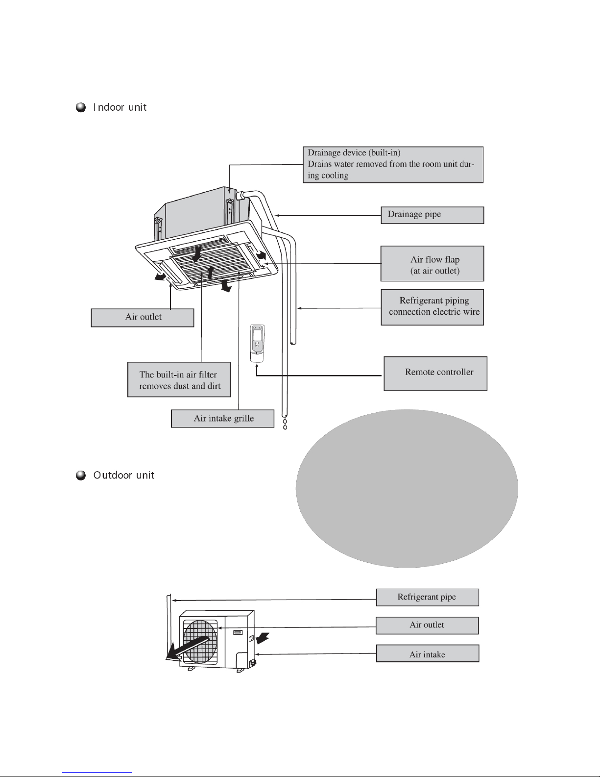
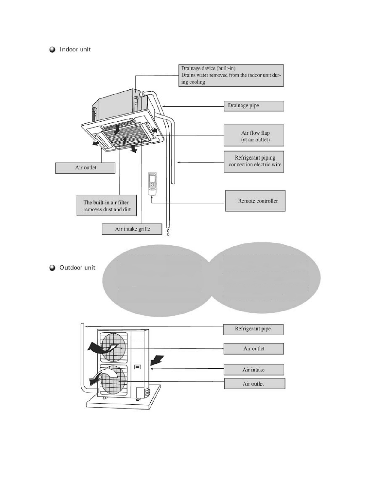
1.Names and functions of parts
1
ULS 12
ULS 18
ULS 24
ICI 18
ICI 24
ICI-12
2
ULS 36 ICI 36
ULT 36 ICI 36
ULT 45 ICI 45
ULT 50 ICI 50
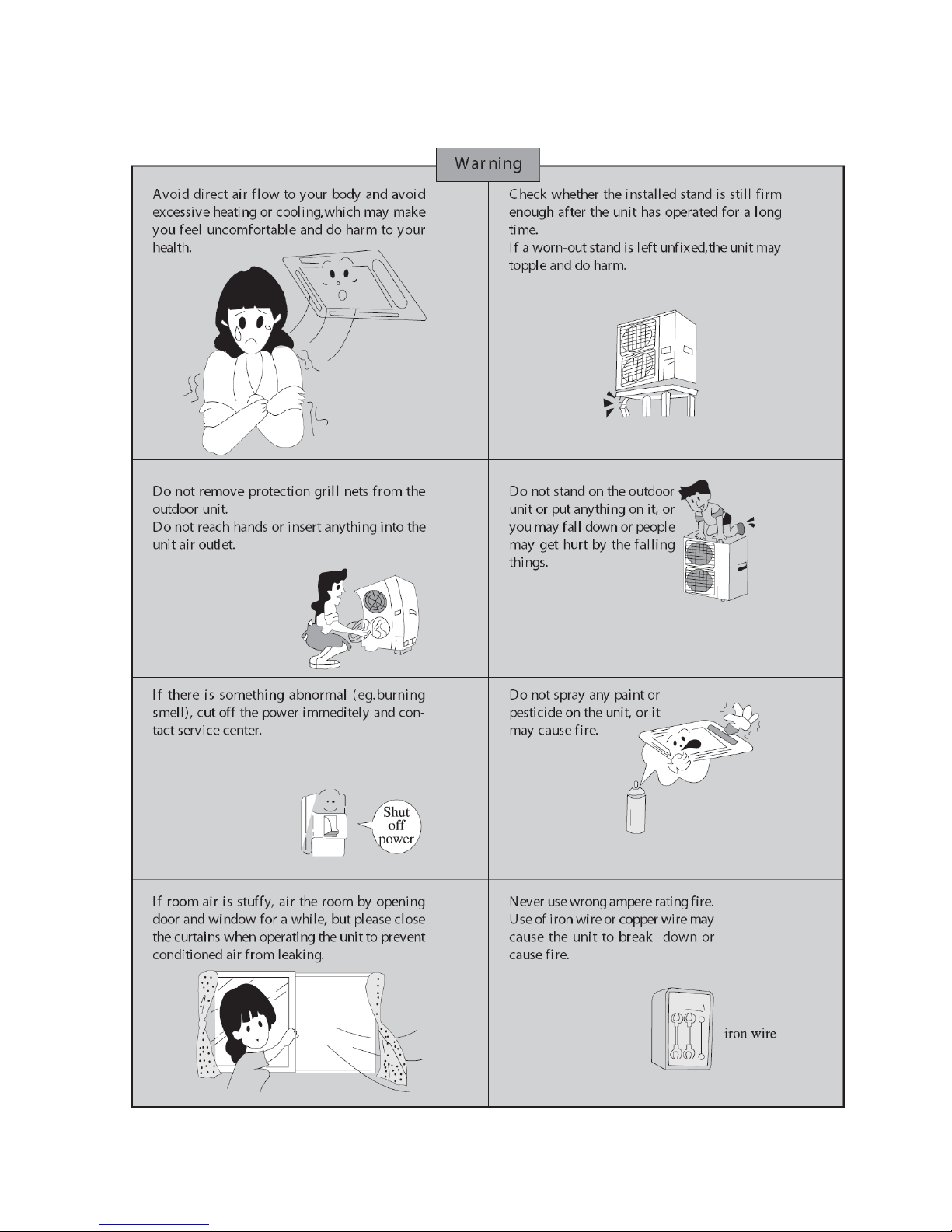
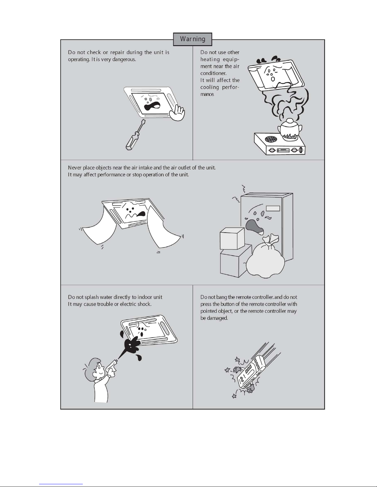
2、Safety cautions
●Read the following carefully to assure safe use.
3
NOTE: Children should be supervised to ensure that they do not play with the appliance.
NOTE: This appliance is not intended for use by persons (including children) with reduced
physical, sensory or mental capabilities, or lack of experience and knowledge, unless they
have been given supervision or instruction concerning use of the appliance by a person
responsible for their safety.
4
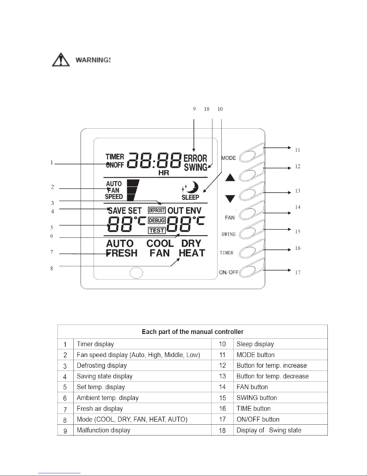
3、Wire controller(standard fitting)
Never install the wire controller in a place where there is water leakage.
Avoid bumping, throwing, tossing or frequently opening the wire controller.
Fig.1
5

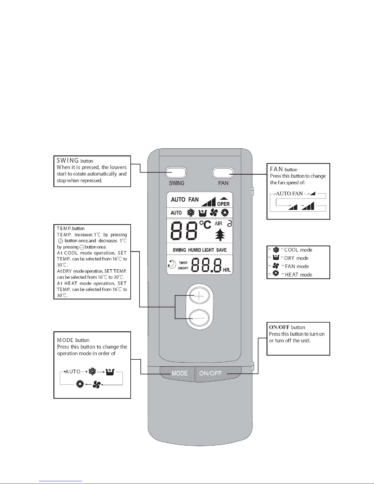
1) ON/OFF (Fig.2)
★ Press this button the unit will start.
★ When repress the button, the unit will stop running.
Fig 2
2) Fan control(Fig. 3) (The relevant contents are shown in the figure.)
★ Press this button to change the fan speed of:
★ At the DRY mode: the fan speed will be set for
low fan speed automatically.
Fig 3
3) Temperature adjustment(Fig.4)
★ Press the temperature adjustment button
6
▲:For temperature increase;
▼:For temperature decrease.
(Press this button once, the temperature will be
increased or decreased by 1℃.)
NOTE: Lock function: Press “▲” and ” ▼” at the same
time for 5 seconds, the set temp. indicating area shall Fig 4
display “EE” and all keys’ response shall be shut off, all buttons will sound; and repress the
“▲” and ” ▼” simultaneously for 5 seconds, the lock function will be released. When the
displayer of long-distance monitoring or central controller has been shielded, the buttons and
remote control signal will be shielded too, the setting temp. will display “CC”.
★ The set temperature range under each mode:
HEAT -------- 16℃~30℃
COOL -------- 16℃~30℃
DRY -------- 16℃~30℃
FAN -------- The temp. cannot be set up
AUTO -------- The temp. cannot be set up
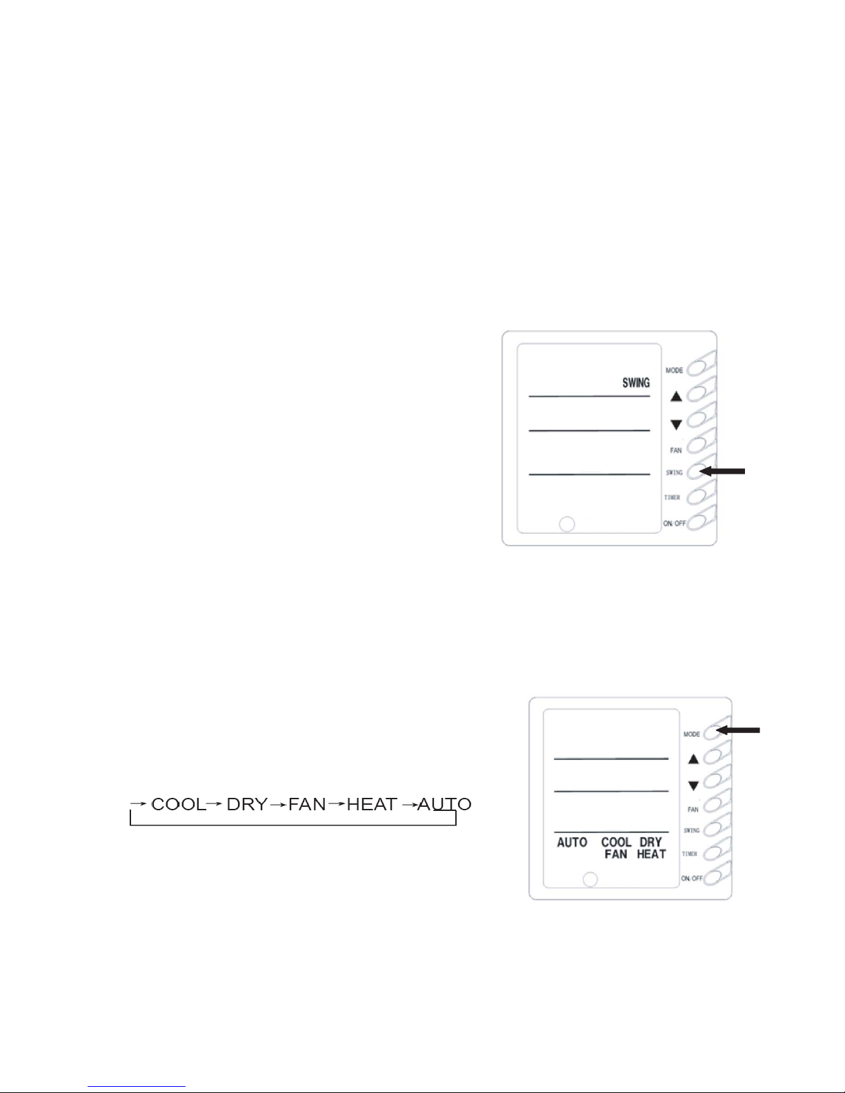
4)Swing mode set up(Fig.5)
ill
op running in Swing mode.
★ When pressing “SWING" button, the type style
"SWING" will be displayed on LCD, the unit will run
in Swing mode
★ when repressing the “SWING” button, that the type
style "SWING" will be disappeared, and the unit w
st
Note: The SLEEP function could be set up by wireless remote control.
5) Running mode setup(Fig.6)
★ When press this button once, the operation mode will
be changed as follow:
★ At “COOL” mode, the “COOL” icon will light on, the
current temperature should be set up lower than the
ambient temperature. If the setting temperature is
Fig 6
higher than the ambient temperature, the COOL mode will not start, only the fan is active.
7
Fig 5
★ In “DRY” mode, the “DRY” icon will light on. The inner fan will run at low fan speed in a
certain range. This DRY efficiency in this mode is more obvious than the one in COOL
mode, and the power saving efficiency is better.
★ In “HEAT” mode, the “HEAT” icon will light on. The setting temperature should be set up
higher than the present temperature; if it is lower than the present ambient temperature, the
HEAT mode is unavailable.
★ In “FAN” mode, the “FAN” icon will light on.
★ In “AUTO” mode, the “ AUTO” icon will light on, according to the ambient temperature, the
unit will automatically adjust the running mode.
★ In “HEAT” mode, when the outdoor temperature is lower and high humidity, and it frosted
in outdoor unit, and the heating efficiency will be reduced. If it is in this case, the controller will
start defrosting automatically, and displays “DEFROST” icon.
NOTE: There is no HEAT mode in the cooling only unit, after the power saving set up, the
auto mode will be shielded.
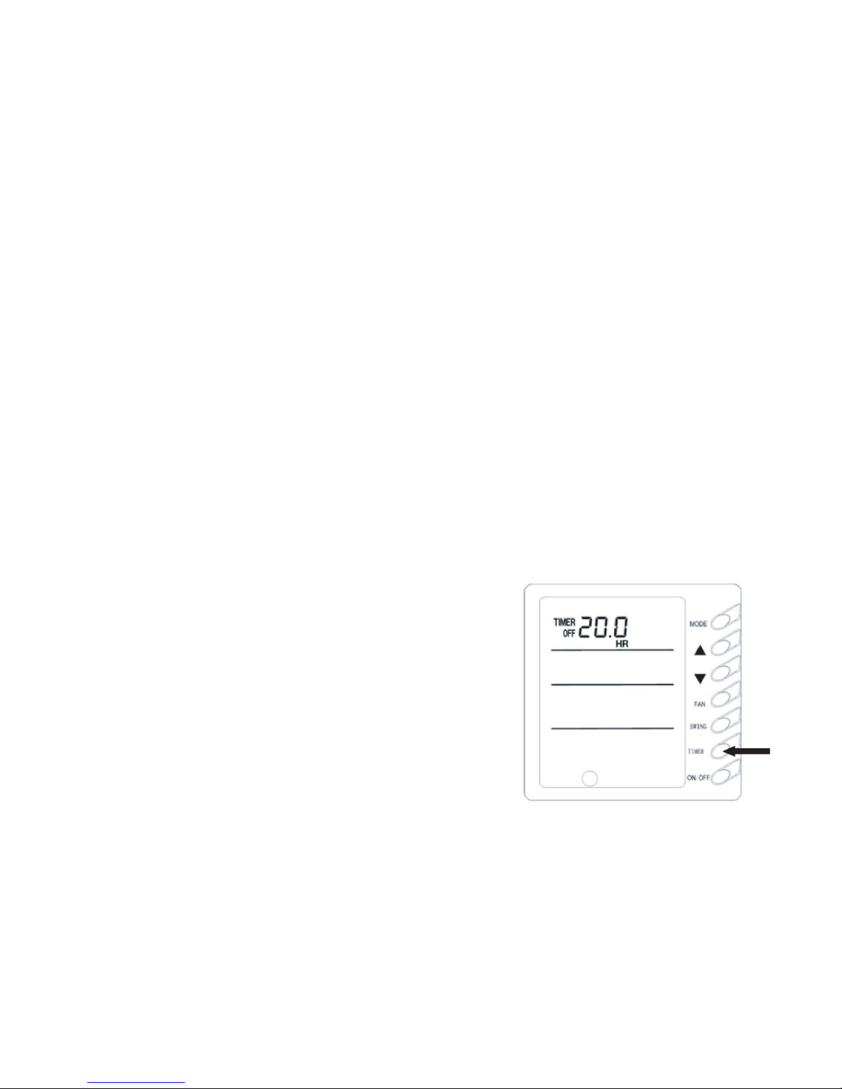
6) TIMER setup (Fig. 7)
At unit turned off, the timer on could be set up, at unit
turned on, the timer off could be set up. After pressed the
“TIMER” button, the unit could be set up, and the
TIMER icon flashes, by pressing the buttons “▲”,“▼”
could increase or decrease the time of timer, when
repress the “TIMER” button, the Timer is valid, the units
will start calculate the time. When the unit is in the
TIMER, press the “TIMER” button could cancel the time. Fig 7
NOTE:
When the protection or malfunction happens after the timer on was set up, the
time place will display the protection or the error codes, the timer button cannot be
setup, but the time you have setup before is still available.
8
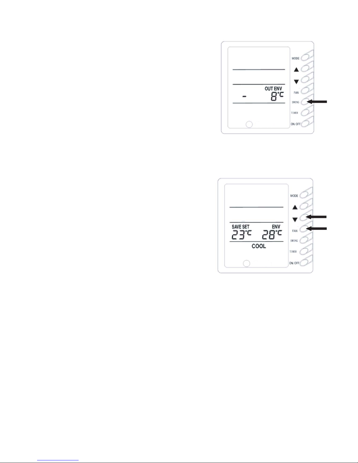
7) Outer ambient temperature display (Fig. 8)
9
Under normal condition, “ENV” will display the room
ambient temperature, at unit turned on, or unit turned off
status, press “SWING” button last for 5 seconds, the
LCD will display “OUT ENV”.
① If tested the outdoor temperature is the positive value,
that the setting temperature will not be displayed, the
original environment temperature displayer displays the Fig 8
system internal tested outdoor environment
temperature.
② If tested the outdoor temperature is the negative
value, the original environment temperature displays the
system inner tested the absolute value of the out
environment. After displayed the outdoor environment
temperature 10 seconds later, the system will back to
the room ambient temperature displaying surface. Fig 9
NOTE: If the unit has been unconnected with the outdoor ambient sensor, this
function will be unavailable.
8) SAVE set up (Fig.9)
At unit turned off, to press the “FAN” +“▼” buttons continuously for 5 seconds, adjust the Saver
set menu, at this time displays “SAVE” “COOL” icons, (if it is the first setup, that will display the
initial value:26℃), at the temperature setting district, it displays the lower limit temperature,and
the set temperature flashes, by pressing“▲”and“▼”buttons to set the cooling temperature lower
limit (the setting range is 16~30), press “ON/OFF” button to confirm; by pressing “▲” and“▼”
buttons to set cooling temperature upper limit, it will flash and display at ambient temperature,
( the setting range is 16-30) , and press “ON/OFF” button to confirm.
NOTE:The upper limit temperature should not be lower than the setting lower limit temperature.
If upper limit temperature is lower than the lower limit temperature, the system will default. The
higher is the upper limit temperature, the lower is the lower limit temperature. Press “MODE”
button, to complete the save setting in COOL, DRY mode, and transfer to the save setting in
HEAT mode (There is no the function in cooling only unit), at this time, it displays the “SAVE”,
“HEAT” icons, after setup has been completed, then press “FAN” +“▼” button last for 5 seconds,
and quit the SAVE setting operation. If the SAVE interface has been opened, the system will
respond to the last button input after 20 seconds, there is no any operation, the system will quit
the menu, and displays the normal unit off interface.
The above setting has been completed, the system will display ”SAVE” icon, no matter
by buttons on displayer or the wireless remote control, the setting temperature should not
exceed the former SAVE setup temperature range, for example as show in Fig. 9, we set up
the cooling lower limit is 23℃ in SAVE setting, the upper limit is 27℃ , the user can set the
cooling temperature between 23℃ to 27℃ by the wireless remote control and buttons on
displayer.
If the set up upper limit temperature is the same with the lower limit temperature that the
system only can run at the corresponding modes at the set temperature.
After the SAVE mode set up, at unit turned off, press the “FAN” +“▼” buttons for 5 seconds,
will quit the SAVE setting function, but the former
setting data will not clear, and the next time SAVE
setting will be the initial setting temperature.
After powered off, the SAVE setup function will be
memorized, the next time power on, the SAVE setting
is still active.
Set up the SAVE mode, the SLEEP, AUTO modes
will shield.
Fig 10
10
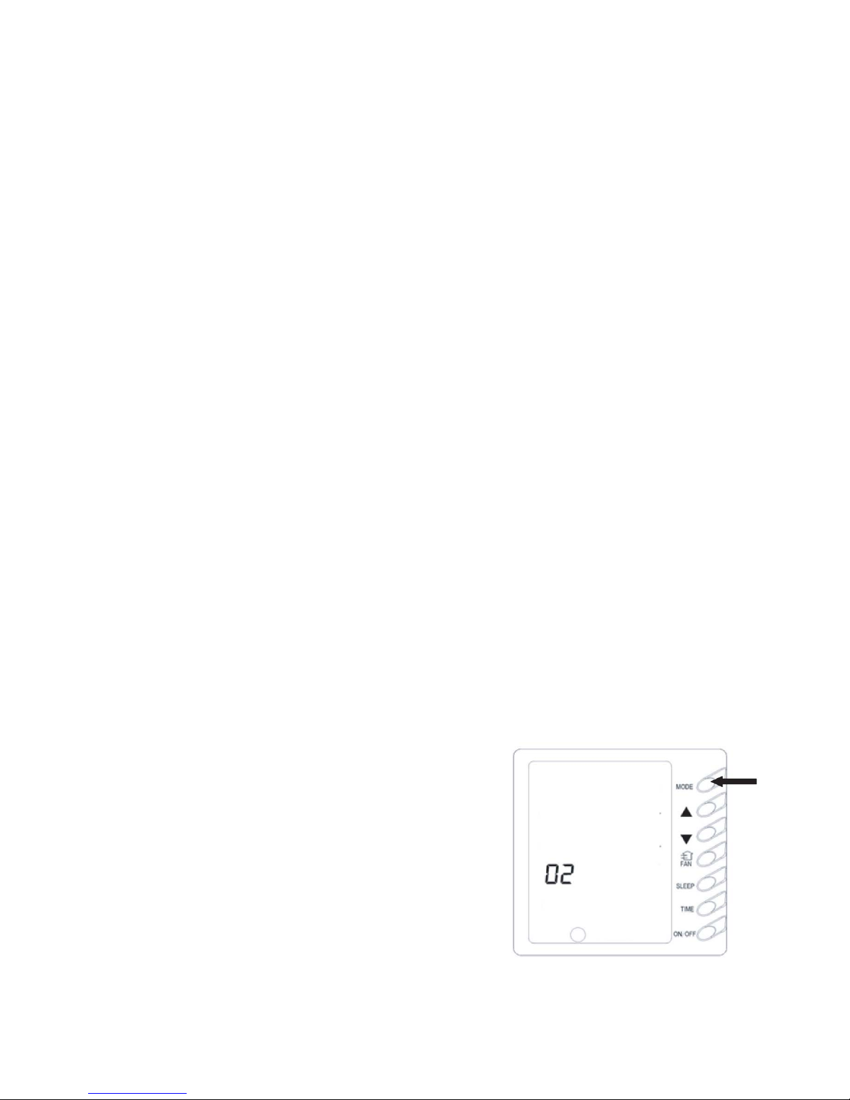
9) MEMORY function setup (Fig. 10)
Press and hold the “MODE” key for 10 seconds when the unit is shut off to switch set values
so as to decide if the unit operating status or shut off status shall be memorized after a power
fail. If the set temperature area displays 01, it means the unit operating status or shut off status
shall be memorized after a power fail; 02 means the operating status or shut off status shall not
be memorized. Press the "ON/OFF" key to store the set value and exit the seting.
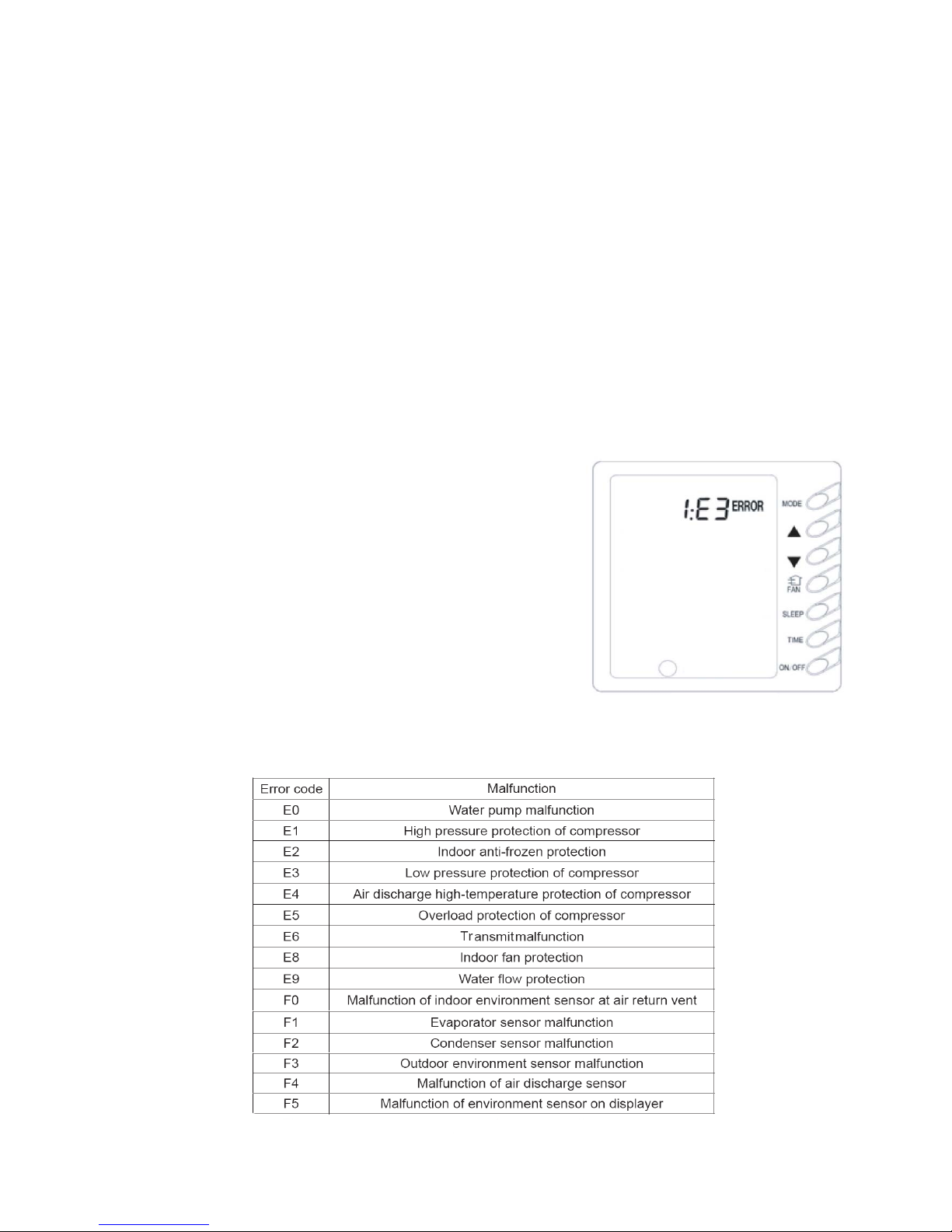
10) Malfunction display (Fig.11)
When the malfunction happened during operation, the displayer will display “ERROR” icon
and flash, and meanwhile will display the error code,
when there are multi-malfunction happened, the displayer
will display the error codes circularly. The first number
denotes the system number, if there is only one system in
the display, it will display the system number 1 , the
following two are error codes. For example as show in
right figure, that denotes the system 1, low-pressure
protection of compressor. Fig 11
The meaning of error codes as show in below:
11
1
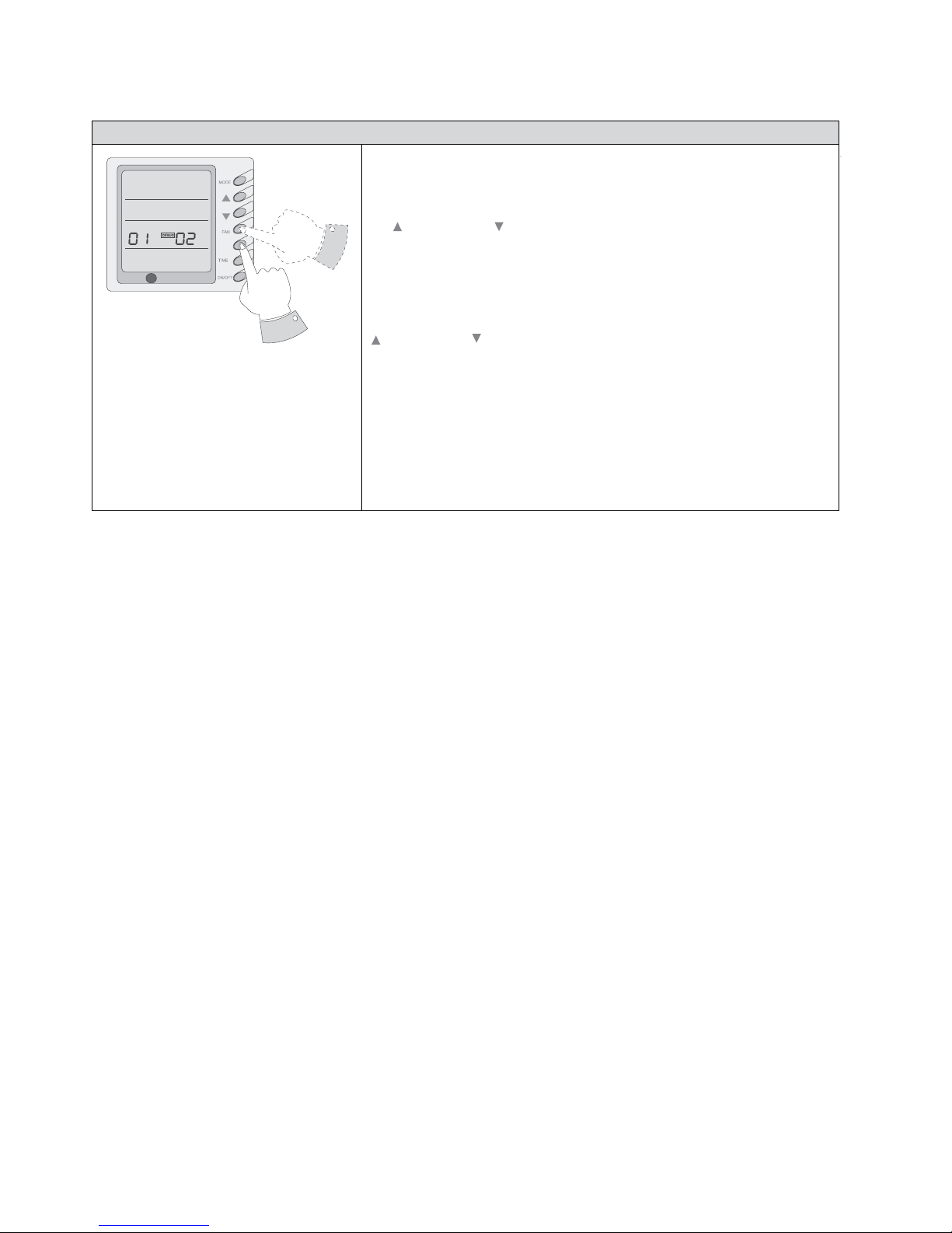
11) Debug Function Setting
Debug Function Setting
When the unit is shut off, press the “FAN” key and the “SWING” key
Simultaneously to activate the debug menu. Now the LCD displays
“DEBUG”. Press the “MODE” key to select setting item and use
the( ) key or the ( ) key to set actual value.
Setting of Ambient Temp. Sensor
Under the debug mode , press the “MODE” key so as to display “01”
On the set temperature area (at the left of “DEBUG”). The OUT ENV
area (at the right of “DEBUG”) displays setting status. Now use the
( ) key or the ( ) key to select from the following two settings:
The indoor room temperature is measured at the air intake(Now the
OUT ENV area displays 01).
The indoor room temperature is measured at the wire controller (Now
the OUT ENV area displays 02).
The indoor room temperature is measured at the wire controller when
the mode is 'heating' or 'auto'. At other modes, it is measured at the
air intake (Now the OUT ENV area displays 03) ,The default is 03.
R
SWING
12
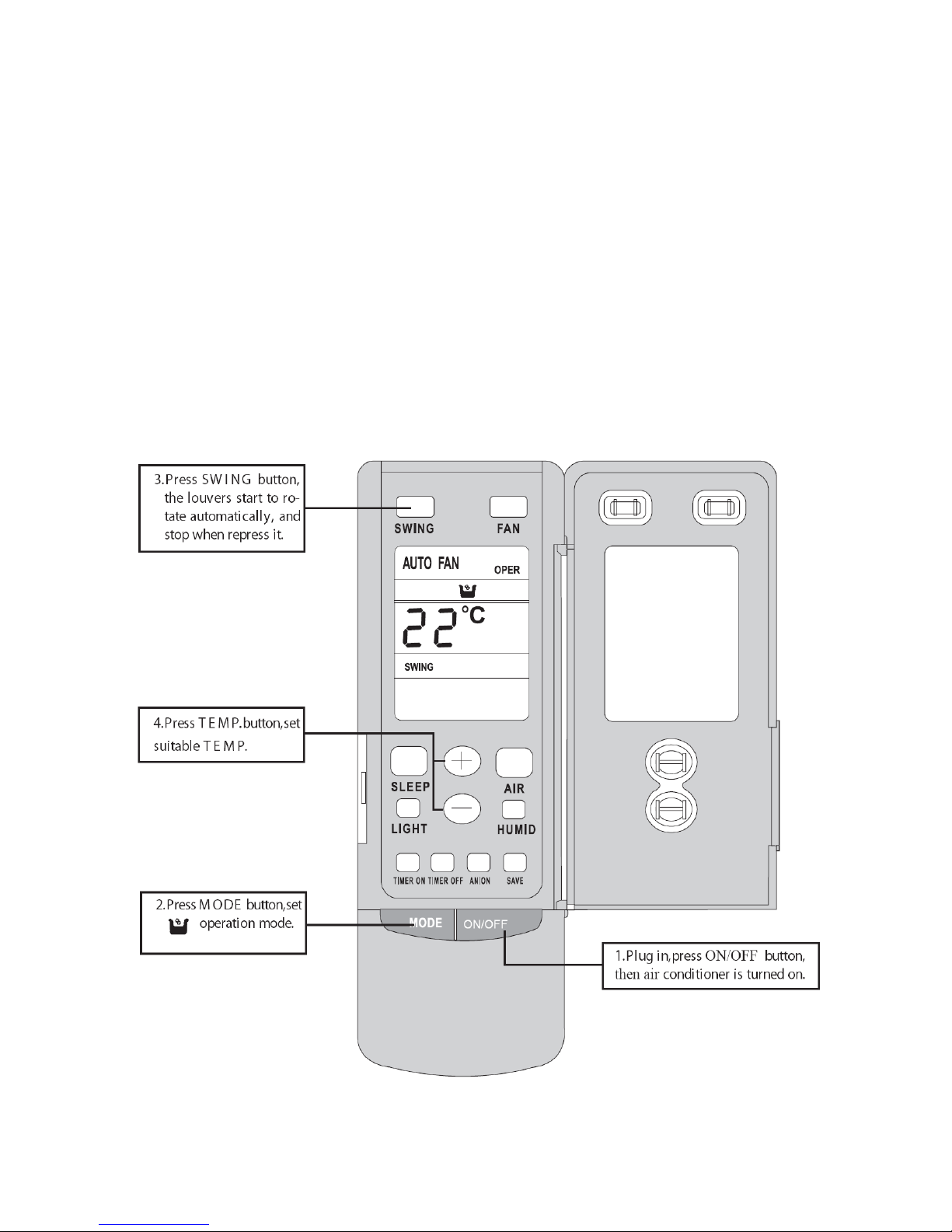
4、Remote control operation procedure(standard fitting)
★ Name and Function-Remote Control
Note:
● Be sure that there are no obstructions between receiver and remote controller.
● Don’ t drop or throw the remote controller .
● Don’ t let any liquid in the remote controller and put the remote controller directly under the
sunlight or any place where is very hot.
13
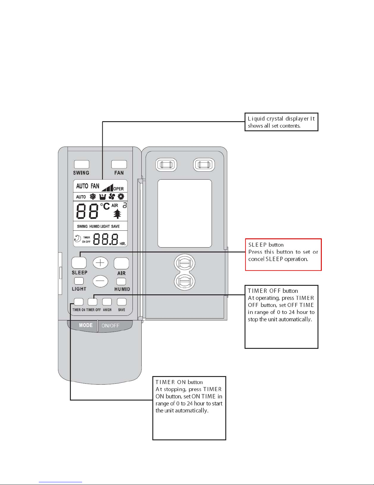
★ Name and Function-Remote Control. (Remove the cover )
Note: This type of remote controller is a kind of new current controller. Some buttons of
the controller which are not available to this air conditioner will not be described below.
Operate on unmentioned buttons would not impact on the normal use.
14
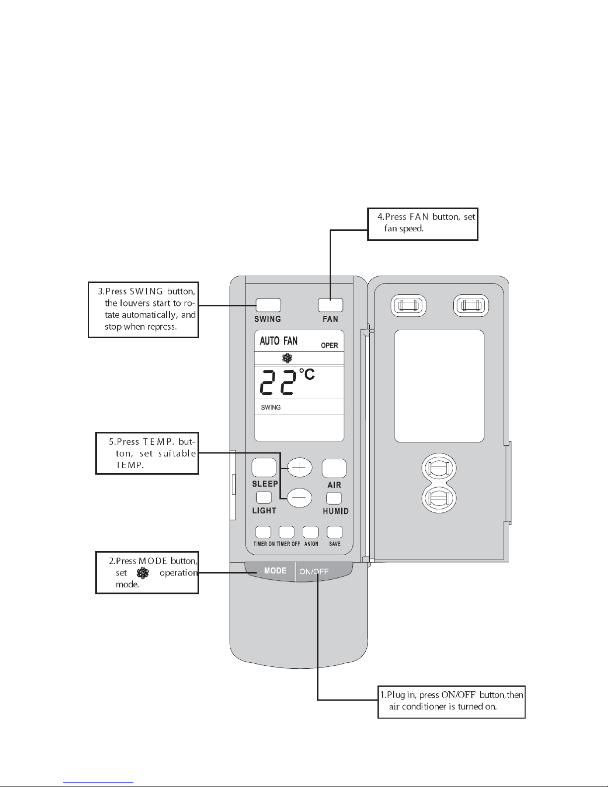
★ COOL mode operation procedure
● According to difference between room temp. and set temp., microcomputer can control
cooling on or not.
● If room temp. is higher than set temp., compressor runs at COOL mode.
● If room temp. is lower than set temp., compressor stops and only indoor fan motor runs.
Set T EMP. should be in range of 16℃ to 30℃.
15
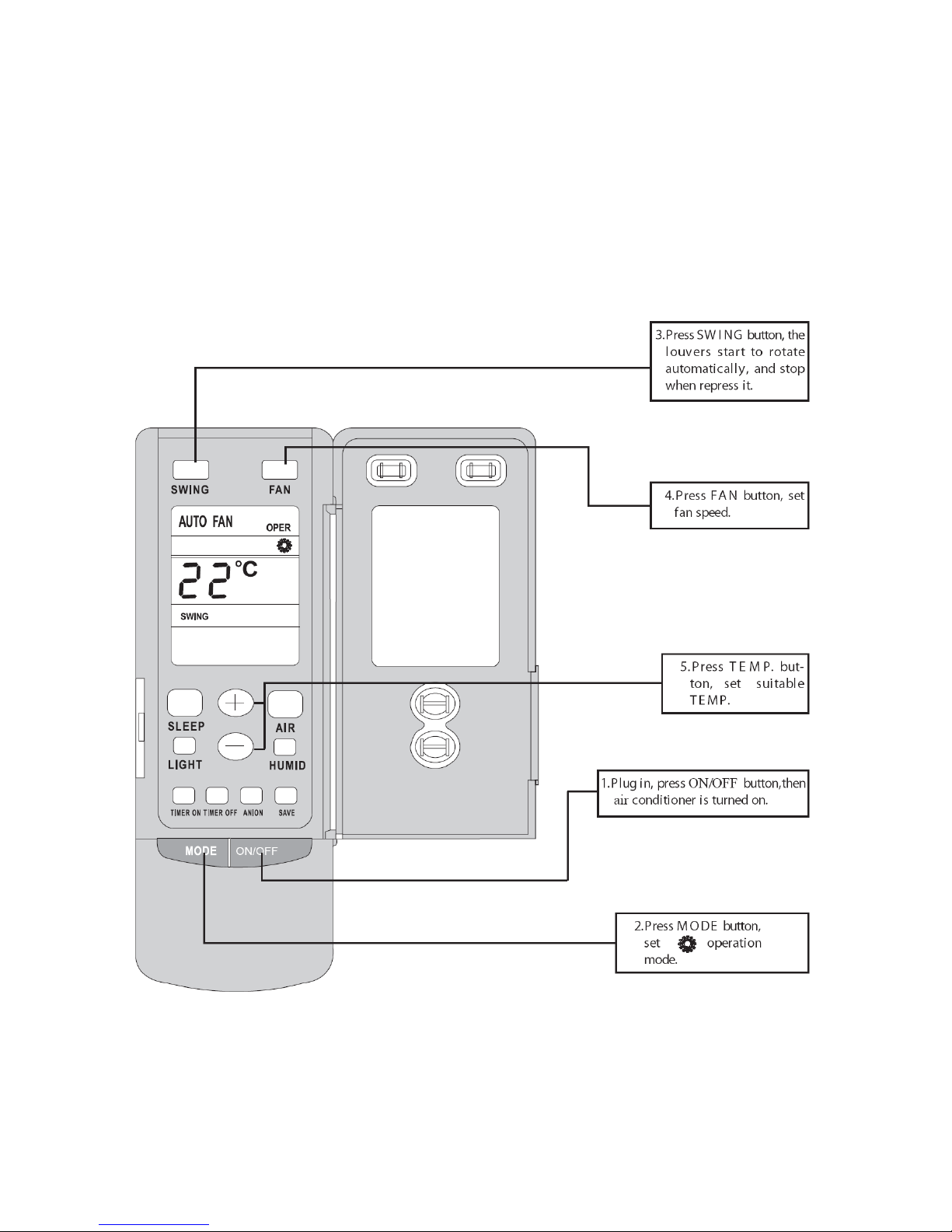
★ HEAT mode operation procedure
●If room temp. is lower than set temp., compressor runs at HE AT mode;
●If room temp. is higher than set temp., compressor and outdoor fan motor stop, only indoor
fan motor runs.
●Set T EMP. should be in range of 16℃to 30℃
16
★DRY mode operation procedure
● If room Temp. is more than 2 below Set TEMP. , compressor and outdoor unit fan motor
stop, indoor unit fan motor runs at low speed.
● If room Temp. is more than 2 above Set TEMP. , compressor and outdoor unit fan motor
run as COOL mode , the indoor unit fan motor runs at low speed.
17
● If room Temp. is between 2 of Set TEMP. , the compressor and outdoor unit fan motor
will run for 6 minutes and stop for 4 minutes, and always in such a cycle, the indoor unit fan
motor will run at low speed.
℃
℃
℃
±
 Loading...