

INVENTOR H3TBI-100, H3TBO-100, H3TBI-120, H3TBO-120 Owner's Manual

1
Models
H3TBO-120
H3TBI-120
H3TBO-100
H3TBI-100
Ducted unit
Owner’s Manual
66129905484
Thank you for selecting INVENTOR
air conditioners.Please read this
manual
carefully before operation and keep it for
further reference.
HTBI-120B/HTBO-120B

CONTENTS
1、Safety precautions .......................................................................................................................... 1
2、Displaying Part ................................................................................................................................2
2.1 LCD Display of Wired Controller................................................................................................................2
2.2 Instruction to LCD Display..........................................................................................................................3
3、Buttons............................................................................................................................................. 4
3.1 Silk Screen of Buttons .................................................................................................................................4
3.2 Instruction to Function of Buttons ...............................................................................................................4
4、Installation of Wired Controller and Project Debugging.............................................................. 5
4.1 Installation of Wired Controller ...................................................................................................................5
5、Instruction to Operation.................................................................................................................. 6
5.1 On/Off..........................................................................................................................................................6
5.2 Mode Setting................................................................................................................................................6
5.3 Temperature Setting .....................................................................................................................................7
5.4 Fan Speed Setting * .....................................................................................................................................7
5.5 Swing Control Function *............................................................................................................................8
5.6 Timer Setting................................................................................................................................................8
5.7 Air Exchange Setting*..................................................................................................................................9
5.8 Sleep Setting ..............................................................................................................................................10
5.9 Turbo Function Setting ..............................................................................................................................11
5.10 Save Function Setting ..............................................................................................................................12
5.11 E-heater setting * .....................................................................................................................................13
5.12 Blow Function Setting...........................................................................................................................14
5.13 Quiet Function Setting..........................................................................................................................15
5.14 Debugging Functions............................................................................................................................16
5.14.1 Ambient Temperature Sensor Setting ....................................................................................16
5.14.2 Three Grades of Speed for Indoor Fan..................................................................................17
5.15 Other Functions.....................................................................................................................................17
5.15.1 Lock Function ............................................................................................................................17
5.15.2 Memory Function ......................................................................................................................17
5.15.3 Gate-control Display Function* ...............................................................................................17
5.15.4 Enquiry of Outdoor Ambient Temperature ............................................................................18
5.15.5 Selection of Centigrade and Fahrenheit
................................................................................18
6、Error Display.................................................................................................................................. 19
7、Names and functions of remote control buttons........................................................................ 21
8、Changing batteries and notices ................................................................................................... 24
9、Weekly Timer Function ................................................................................................................. 25
10、Installation instruction................................................................................................................ 27
10.1 Selection proper installation location.......................................................................................................27
10.2 Install the indoor unit...............................................................................................................................27
10.3 Install the outdoor unit.............................................................................................................................32
10.4 Electric wiring..........................................................................................................................................34
11、Trial run and installation checking.............................................................................................37
12、Care and Maintenance................................................................................................................. 39
13、Appendix...................................................................................................................................... 40

1
1、Safety precautions
1.1 Safety notice
Before using the appliance, read this manual thoroughly and operate under its direction.
“WARNING” and “ATTENTION” have the following meanings in these instructions:
△WARNING This mark indicates procedures, which if improperly performed, might lead to the
death or serious injury of the users.
△ATTENTION This mark indicates procedures, which if improperly performed, might possibly result
in personal injury to the user, or damage to property.
△WARNING
z Do not use or place combustible and explosive gas or liquid near the air conditioner.
z To optimize the life of the appliance, do not install the air-conditioning unit by yourself.
z Do stop operation and turn off the power supply immediately in the event of a malfunction (burning
smell, etc.).
z Don’t remove the fan guard and not insert fingers or objects into the outlet ports of the indoor and
outdoor unit.
z Do not check or fix the air-conditioning unit while it is running.
z Do not pour water into the air-conditioning unit and not operate it with a wet hand.
z The air-conditioning unit is not equipped with a device to suck fresh air from the outdoors, so when you
are using gas or petrol in the same room, or you feel the room air is dirty, please open the door or
window to exchange the air, but this can affect the adjustment of air conditioning.
ATTENTION △
z Ensure the power supply correspond to the nameplate and check the security of the power source
before installation.
z Make sure that the wires, pipes and drain hose are properly connected before operation to avoid a
fire or electric shock.
z Don’t let children operate the ducted air-conditioning unit.
z Turn off the power supply whenever cleaning the air-conditioning unit or changing the air filter.
z Switch off power source when the units will not be operated for a long period.
z Do not step or place objects on the air-conditioning unit.
z The appliance shall not be installed in the laundry
1.2 Power supply demand
1) Provided sufficient capacity of power supply and the cross area of electrical wires.
2) Confirm the reliable earth connection, and the earth wire should be connected to special device of
the building. Never connect the earth wire to the gas pipe, water pipe, the earth wires of telephone
and lighting rod.
3) Make sure that the wiring is done by the qualified technicians according to the relevant regulations.
4) In fixed circuit, there must be electricity leakage protection switch of enough power capacity and air
switch with enough space.
5) An all-pole disconnection device which has at least 3mm separation distance in all pole and a
residual current device(RCD)with the rating of above 10mA shall be incorporated in the fixed wiring
according to the national rule
6) The appliance shall be installed in accordance with national wiring regulations
7) The temperature of refrigerant circuit will be high, please keep the interconnection cable away from
the copper tube.
2
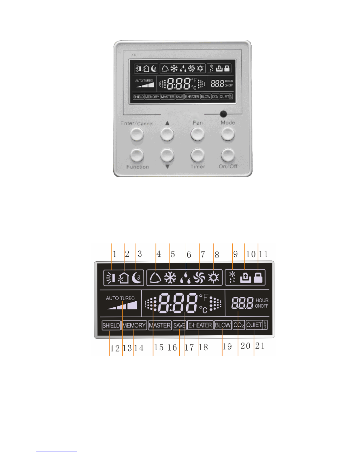
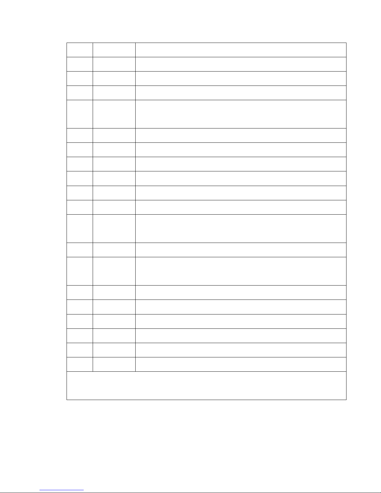
2、Displaying Part
Fig.2.1 Outline of wired controller
Fig.2.2 LCD display
2.1 LCD Display of Wired Controller
3
No. Description Instruction to Displaying Contents
1 Swing Swing function
2 Air Air exchange function
3 Sleep Sleeping states
4
Running
mode
Each kind of running mode of indoor unit (auto mode)
5 Cooling Cooling mode
6 Dry Dry mode
7 Fan Fan
8 Heating Heating mode
9 Defrost Defrosting state
11 Lock Lock state
12 Shield
Shielding state (buttons, temperature, on/off, mode or save is shielded by
long-distance monitoring
13 Turbo Turbo function state
14 Memory
Memory state (Indoor unit resumes original setting state after power failure
and then power recovery)
15 Twinkle Flicking when unit is on without operation of buttons
16 Save Energy-saving state
17 Temperature Ambient/setting temperature value
19 Blow Blow mark
20 Timer Timer-displayed location
21 Quiet Quiet state(two types: quiet and auto quiet)
There is not Master and CO2 functions for E series ducted type unit and A2 ducted type and cassette
type units
Table 2.1
2.2 Instruction to LCD Display
4
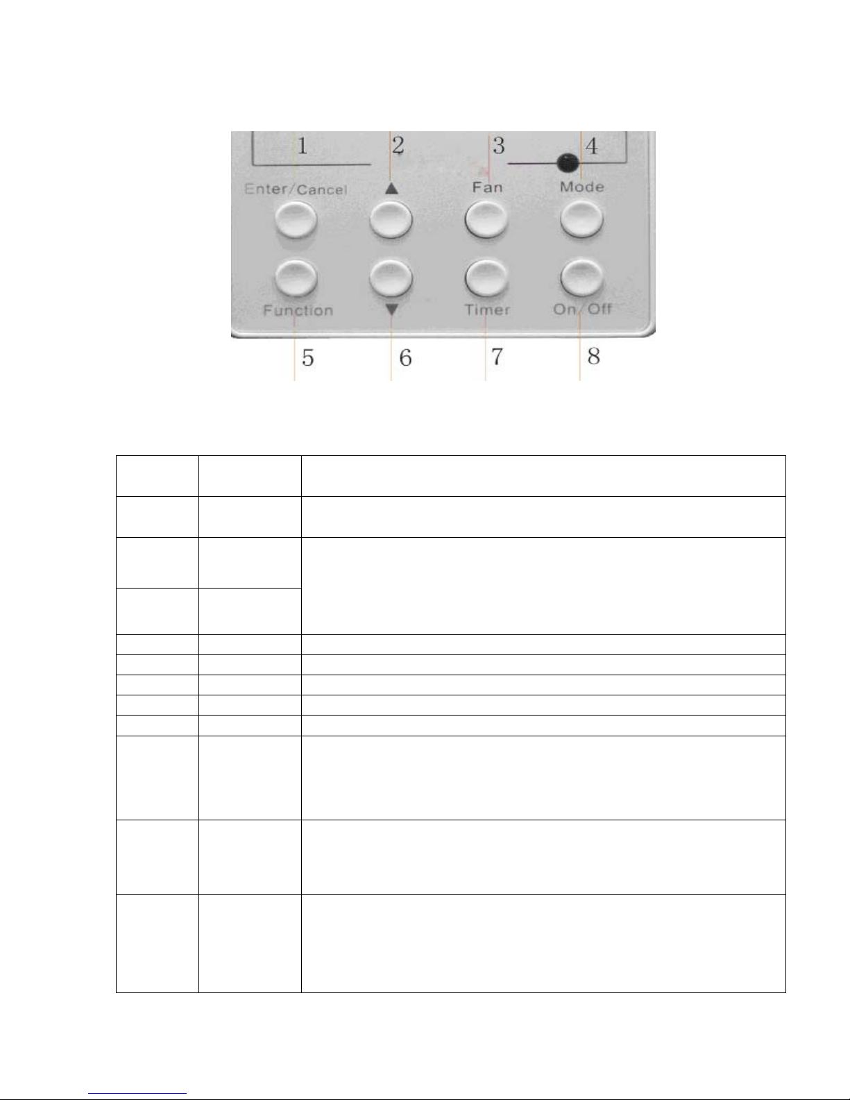
3、Buttons
Fig. 3.1 Silk screen of buttons
No. Description Function of Button
1 Enter/cancel
(1)Function selection and canceling;
(2)Press it for 5s to enquiry the outdoor ambient temperature.
2 ▲
6 ▼
(1)Running temperature setting of indoor unit, range :16~30℃
(2)Timer setting, range:0.5-24hr
(3)Switchover between quiet/auto quiet
3 Fan Setting of high/middle/low/auto fan speed
4 Mode Setting of cooling/heating/fan/dry mode of indoor unit
5 Function Switchover among the functions of air,/sleep/turbo/save/e-heater/blow /quiet
7 Timer Timer setting
8 On/off Turn on/off indoor unit
4 Mode
and
2
▲
Memory
function
Press them for 5s under off state of the unit to enter/cancel memory function
(If memory is set, indoor unit after power failure and then power recovery will
resume original setting state .If not, indoor unit is defaulted to be off after
power recovery. Memory function is defaulted to be off before outgoing.)
2 ▲
and
6
▼
Lock
Upon startup of the unit without malfunction or under off state of the unit, press
them at the same time for 5s in to lock state. In this case, any other buttons
won’t respond the press. Repress them for 5s to quit lock state.
4 Mode
and
5 Function
Enquiry and
setting of
address of
wired
controller
Press them for 5s under unit off at the same time to set address.
Table 3.1
3.1 Silk Screen of Buttons
3.2 Instruction to Function of Buttons
5
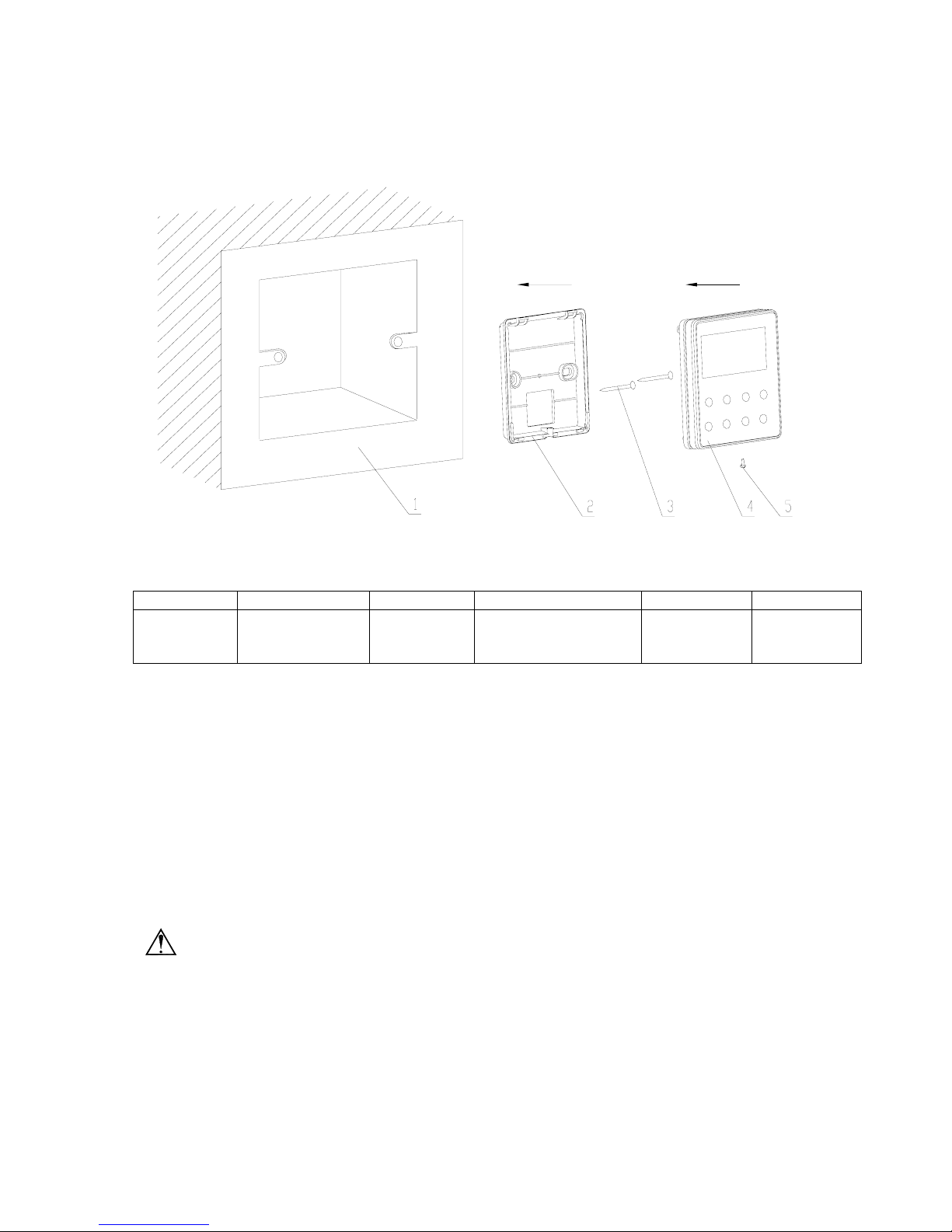
4、Installation of Wired Controller and Project Debugging
Fig.4.1: Sketch for Installation of Wired Controller
Fig.4.1: Sketch for Installation of Wired Controller. Pay attention to the following items during
installation of wired controller:
1. Cut off power supply of heavy-current wire embedded in mounting hole in the wall before
installation. It is prohibited to perform the whole procedure with electricity.
2. Pull out 4-core twisted pair line in mounting hole and then make it through the rectangle hole at
the back of controller’s soleplate.
3. Joint the controller’s soleplate on wall face and then fix it in mounting hole with screws M4X25.
4. Insert the 4-core twisted pair through rectangle hole into controller’s slot and buckle the front
panel and soleplate of controller together.
5. At last, fix the controller’s front panel and soleplate with screws ST2.2X6.5.
Caution:
During connection of wirings, pay special attention to the following items to avoid interference of
electromagnetism to unit and even failure of it.
1. To ensure normal communication of the unit, signal line and wiring (communication) of wired
controller should separate from power cord and indoor/outdoor connection lines. The distance between
them should be kept 20cm in min.
2. If the unit is installed at the place where there is interference of electromagnetism, signal line and
wiring (communication) of wired controller must be shielding twisted pair lines.
4.1 Installation of Wired Controller
No. 1 2 3 4 5
Description Socket’s base
box installed in
the wall
Soleplate of
controller
Screw M4X25 Front panel of
controller
Screw
ST2.2X6.5
6
5、Instruction to Operation
Press On/Off button to turn on the unit.
Repress this button to turn off the unit.
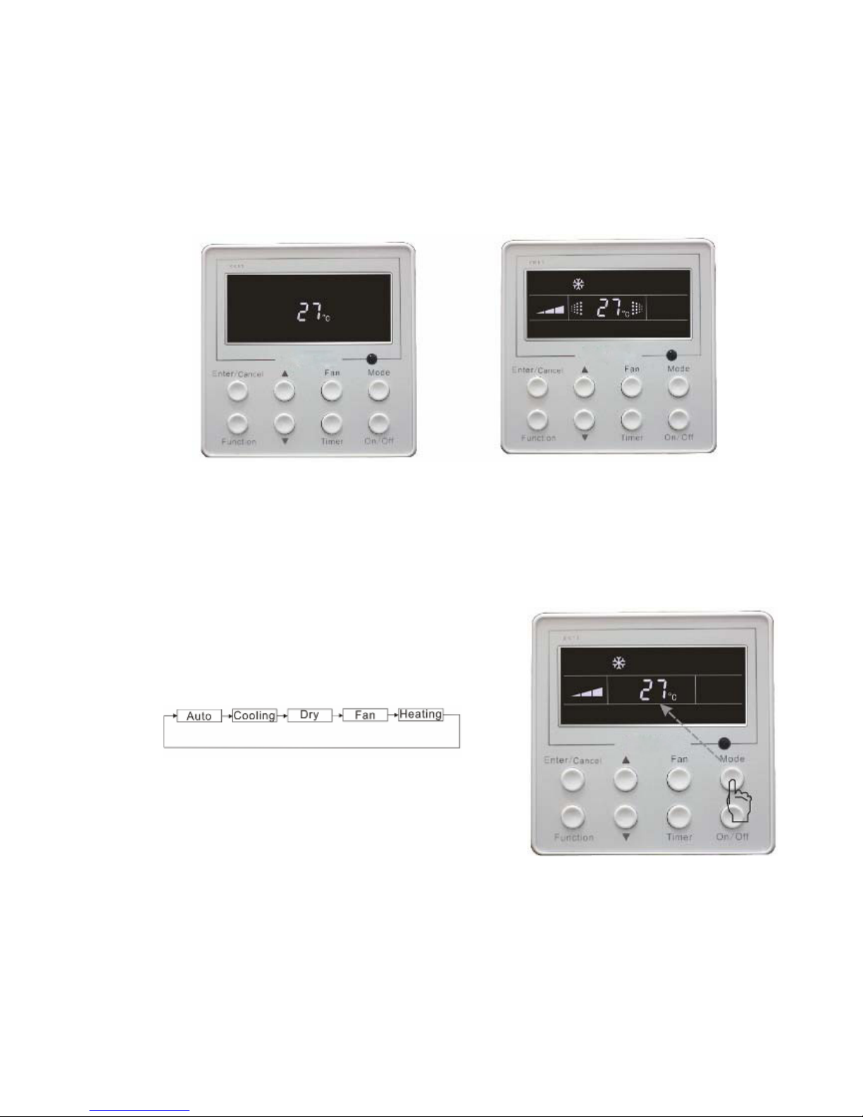
Note: The state shown in Fig.5.1 indicates off state of the unit after energization. The state shown in
Fig.5.2 indicates on state of the unit after energization.
Fig.5.1 Off state of the unit Fig.5.2 On state of the unit
Under on state of the unit, press Mode button to switch the operation modes as the following
sequence:
Press ▲ or ▼ button for increase or decrease of setting temperature under on state of the unit.
5.1 On/Off
5.2 Mode Setting

7
Fig.5.4
Press ▲ or ▼ button for increase or decrease of setting temperature under on state of the unit. If
press either of them continuously, temperature will be increased or decreased by 1 every 0.5s.℃
In Cooling, Dry, Fan and Heating mode, temperature setting range is 16℃~30℃。
In Auto mode, the setting temperature is un-adjustable.
As shown in Fig.5.3
Fig 5.3
Under on/off state of the unit, press Fan button, fan speed of indoor unit will change as below:
As shown in Fig.5.4
(Indoor unit about can only run at high fan speed mode and fan speed
can’t be modified by wired controller.)
5.3 Temperature Setting
5.4 Fan Speed Setting *
H3TBI-100/H3TBO-100
8
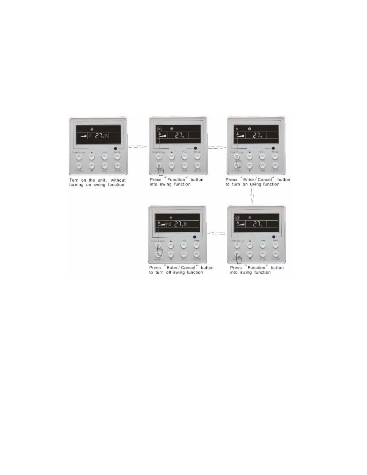
Under on state of unit, press Function button till the unit enters swing control function and then
press “Enter/cancel “ button to turn on turbo control function.
During swing function, press Function button till the unit enters swing control function and then
press Enter/cancel button to cancel swing control function.
Swing control function setting is shown in Fig 5.5
There is no this function for this unit.
Fig.5.5
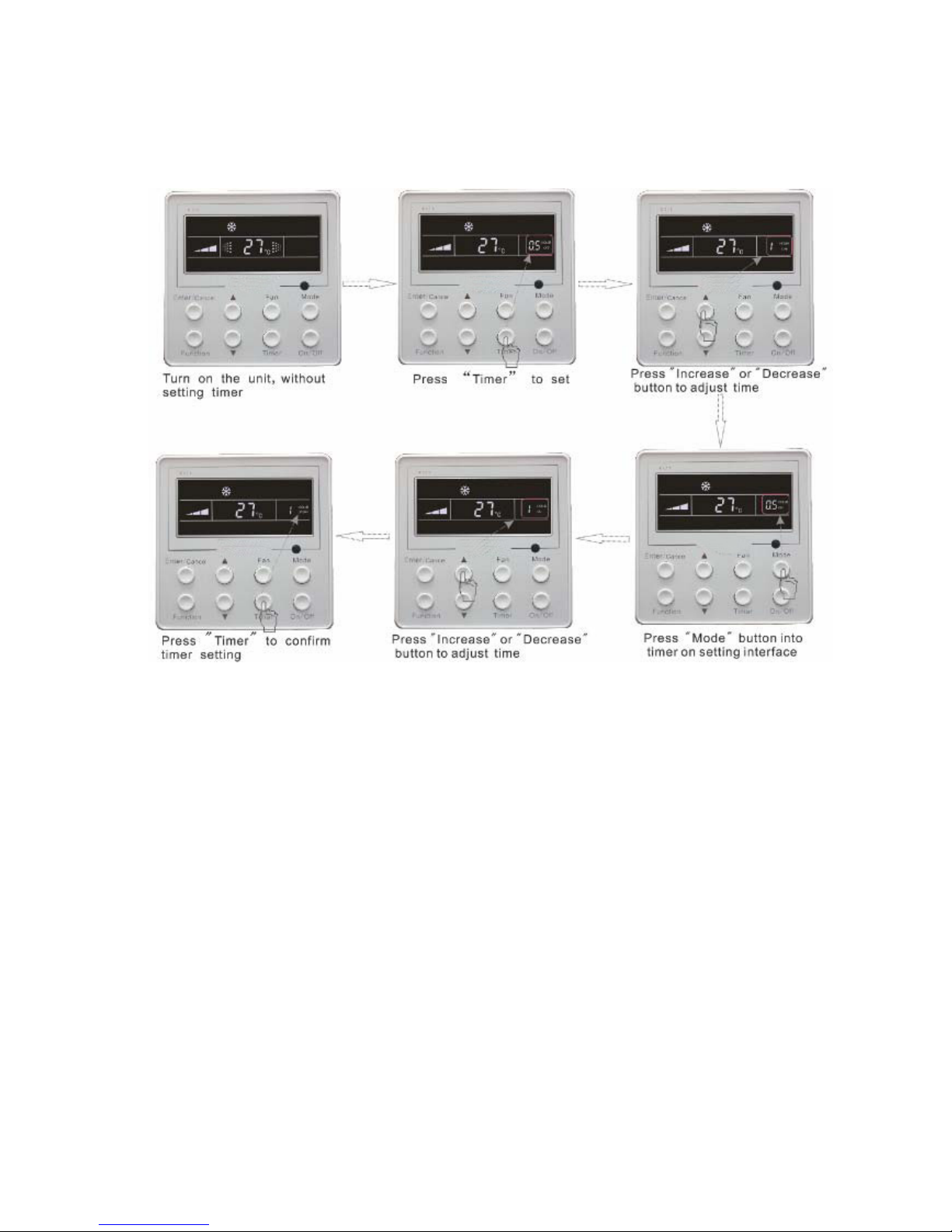
Under on state of the unit, press Timer button to set timer off of the unit. Under off state of the unit,
press Timer button to set timer on of the unit in the same way.
Timer on setting: Under off state of the unit without timer setting, if Timer button is pressed, LCD will
display xx. Hour, ON blinking. In this case, press▲ or ▼ button to adjust timer on and then press Timer
to confirm. If Mode button is pressed before pressing Timer button to confirm, timer mode will be
switched to timer off setting mode. In this case, LCD displays xx. Hour, OFF blinking. In this case,
press▲ or ▼ button to adjust timer off and then press Timer to confirm. When LCD displays xx. Hour
On Off, xx. Hour means time of timer on, but time of timer off won’t be displayed.
Timer off setting: Under on state of the unit without timer setting, if Timer button is pressed, LCD will
display xx. Hour, OFF blinking. In this case, press▲ or ▼ button to adjust timer on and then press
Timer to confirm. If Mode button is pressed before pressing Timer button to confirm, timer mode will be
switched to timer on setting mode. In this case, LCD displays xx. Hour, ON blinking. In this case,
press▲ or ▼ button to adjust timer on and then press Timer button to confirm. When LCD displays xx.
5.5 Swing Control Function *
5.6 Timer Setting
9
Hour On Off, xx. Hour means time of timer off, but time of timer on won’t be displayed.
Cancel timer: After setting of timer, if Timer button is pressed, LCD won’t display xx. Ho ur so that timer
setting is canceled.
Timer off setting under on state of the unit is shown as Fig.5.6
Fig.5.6 Timer setting under on state of the unit
Timer range: 0.5-24hr. Every press of▲ or ▼ button will make setting time increased or
decreased by 0.5hr.If press either of them continuously, setting time will automatically increase/
decrease by 0.5hr every 0.5s.
Note:
1. If both timer on and timer off are set in unit on interface, the wired controller only display time of
time off after confirmation of timer. If both of them are set in unit off interface, only time of timer on is
displayed.
2. Timer on in unit on interface is timed from the time of unit off and timer off in unit off interface is timed
from the time of unit on.
Turn on air function: Under on state of the unit, press Function button into this function setting (Air
mark blinks).AIR 1 displayed at the ambient temperature-displayed location (888) is defaulted (the last
type of AIR will be displayed after adjustment).Press ▲ or ▼ button to adjust air type. Press
Enter/Cancel button to turn on/off air function. After turning on this function, the air mark shows.
There are 10 types of AIR, but only 1-2 types are for remote control. Refer to the following details:
5.7 Air Exchange Setting*

10
1――The unit continuously runs for 60min, and fresh air valve runs for 6 min.
2――The unit continuously runs for 60min, and fresh air valve runs for 12 min.
3――The unit continuously runs for 60min, and fresh air valve runs for 18 min.
4――The unit continuously runs for 60min, and fresh air valve runs for 2 4 min.
5――The unit continuously runs for 60min, and fresh air valve runs for 30 min.
6――The unit continuously runs for 60min, and fresh air valve runs for 36 min.
7――The unit continuously runs for 60min, and fresh air valve runs for 42 min.
8――The unit continuously runs for 60min, and fresh air valve runs for 48 min.
9――The unit continuously runs for 60min, and fresh air valve runs for 54 min.
10――Both of them run.
Turn off air function: During Air function, press Function button into Air function. In this case, air
mark is blinking, and then press Enter/cancel button to turn off this function. Air mark will subsequently
disappear.
Air setting is shown as in fig.5.7:
Fig.5.7 Air exchange device
Note:
In air exchange mode, press Function button or there is not any operation within 5s after the last
button operation, the system will quit from air exchange setting and current energy-saving date won’t be
memorized.
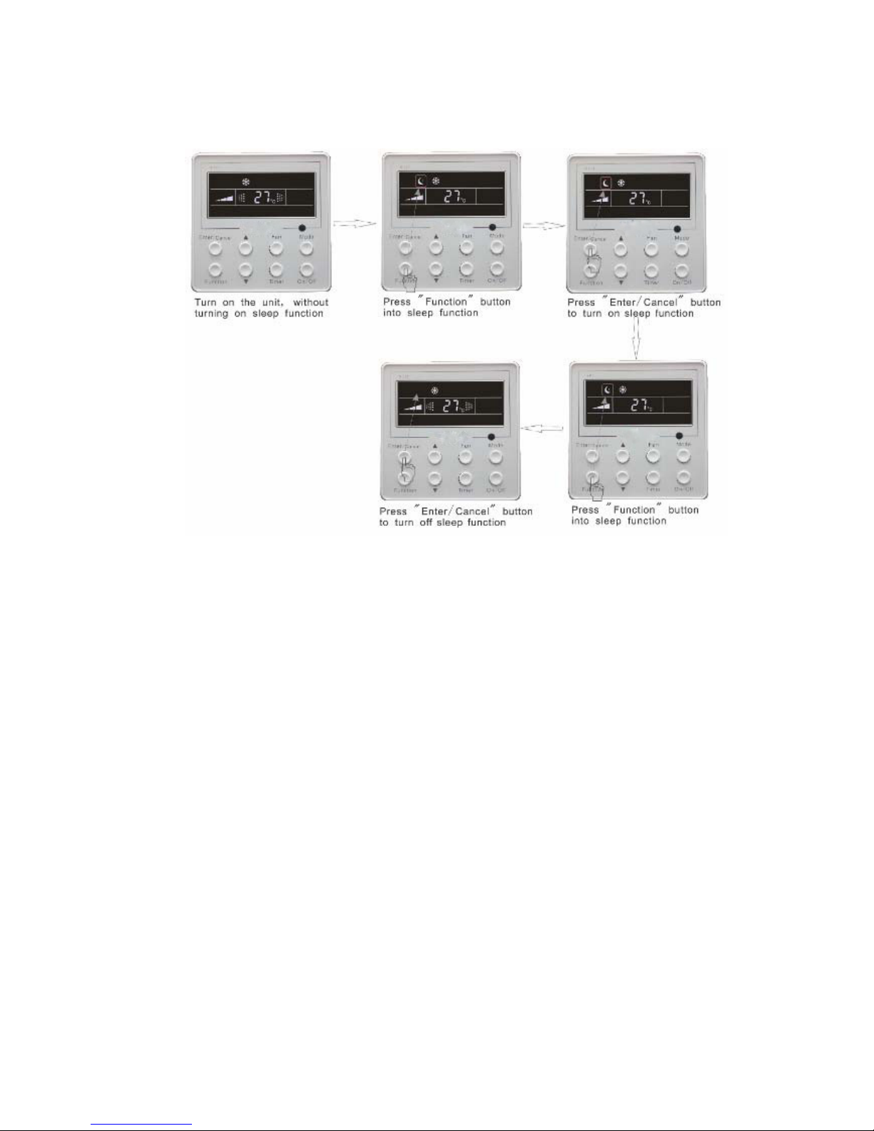
Sleep on: Press Function button under on state of the unit into sleep function and then press
Enter/cancel button to turn on sleeping function.
5.8 Sleep Setting
11
Sleep off: During sleep on state, press Function button into sleep function and then press
Enter/cancel button to turn off this function.
Sleep setting is shown as Fig.5.8:
Fig.5.8 Sleep setting
Sleep off is default after power failure and then power recovery. There is not sleep function in fan and
auto mode.
Note:
In cooling and dry mode, if the unit with sleep function has run for 1 hour, the preset temperature will
be increased by 1℃ and 1℃ in another 1 hour. After that, the unit will run at this temperature. In heating
mode, if the unit with sleep function has run for 1 hour, the preset temperature will be decreased by 1℃
and 1℃ in another 1 hour. After that, the unit will run at this temperature.
Turbo function: The unit at high fun speed can realize quick cooling or heating so that room
temperature can quickly approach setting temperature.
In cooling or heating mode, press Function button till the unit enters turbo function and then press
Enter/cancel button to turn on turbo function.
During turbo function, press Function button till the unit enters turbo function and then press
Enter/cancel button to cancel turbo function.
Turbo function setting is shown in Fig5.9:
5.9 Turbo Function Setting
 Loading...