

Inventor Portable Air Conditioner
Model Number: Cool 8000btu
INSTRUCTION MANUAL
SAVE THESE INSTRUCTIONS FOR FUTURE REFERENCE

Congratulations!
You have purchased the very latest in room air conditioner technology. Your new Inventor high
efficiency room air conditioner will give you many years of dependable service. Many features
have been built into your Inventor air conditioner to assure quiet operation, the best circulation of
cool, dry air, functional controls, and the most economical operation.
Table of contents
BS Plug Wiring ..................................................................................................................................1
Specification ......................................................................................................................................2
WORKING PRINCIPLE ...................................................................................................................3
STRUCTURE ....................................................................................................................................5
OPERATING METHODS ................................................................................................................6
Functions and operation methods of control panel .....................................................................7
Environmental temperature ............................................................................................................8
Operation of wireless remote control ............................................................................................9
Names and functions of wireless remote control ........................................................................9
Guide for operation- General operation ........................................................................................11
Guide for operation- Optional operation .......................................................................................11
Changing batteries and notices .....................................................................................................11
DRAINAGE METHODS...................................................................................................................12
ACCESSORIES AND INSTALLATION OF HEAT EXAUST HOSE ........................................14
MAINTENANCE ...............................................................................................................................16
MALFUNCTION ANALYSIS ...........................................................................................................17
SAFE NOTE AND NOTICE ............................................................................................................18
FAULTY CHECK LIST.....................................................................................................................20
Order Form ........................................................................................................................................21
Disposal
When using this air conditioner in the European countries, the follow
information must be followed:
DISPOSAL: Do not dispose this product as unsorted waste.
It is prohibited to dispose of this appliance in domestic household waste.
For disposal:
A) Contact your local council for disposal.
B) Old products contain valuable resources, which should be recycled as scrap metal.
Wild disposal of waste in forests and landscapes endangers your health when
hazardous substances leak into the ground-water and find their way into the food chain.

BS Plug Wiring
Wiring Instructions: Should it be necessary to change the plug please
note the wires in the mains lead are coloured in accordance with the
following code:
BLUE - NEUTRAL
BROWN – LIVE
GREEN AND YELLOW - EARTH
As the colours of the wires in the mains lead of this appliance may not
correspond with the coloured markings identifying the terminals in your plug,
proceed as follows:
1. The BLUE wire is the NEUTRAL and must be connected to the terminal
which is marked with the letter N or coloured BLACK.
2. The BROWN wire is the LIVE and must be connected to the terminal which
is marked with the letter L or coloured RED.
3. The GREEN/YELLOW is the EARTH and must be connected to the
terminal which is marked with the letter E or or coloured GREEN or
GREEN/YELLOW.
4. Always ensure that the cord grip is positioned and fastened correctly.
If a 13A (BS 1363) fused plug is used it must be fitted with a 13A fuse. If in
doubt consult a qualified electrician.
Wiring for a 13 Amp Plug (BS1363)
Please note. The Earth Terminal is marked with the letter E or Earth Symbol.
1
SPECIFICATION
Model no.
Cool 8000
Cooling capacity
8000 BTU/hr
2345watts
Power/Ampere consumption for cooling
1130 W/ 4.6A
Air volume (H/M/L)
350X300X250 m3/h
Humidity removal capacity
0.75L/hour
Power supply
220-240V~. 50Hz
Compressor
rotary
Noise Level
56/54/52 dB(A)
Refrigerant
R410A (460g)
Fan speed
3
Timer
1~24 hours
Working temperature
Cooling: 16 ~ 30oC
Exhaust pipe
Ø 142x1500mm
Net Weight
24 kgs
Gross Weight
28 kgs
Net Dimension
300x800x355 mm (WxHxD)
Gross Dimension
355x850x565 mm (WxHxD)
2
WORKING
PRINCIPLE
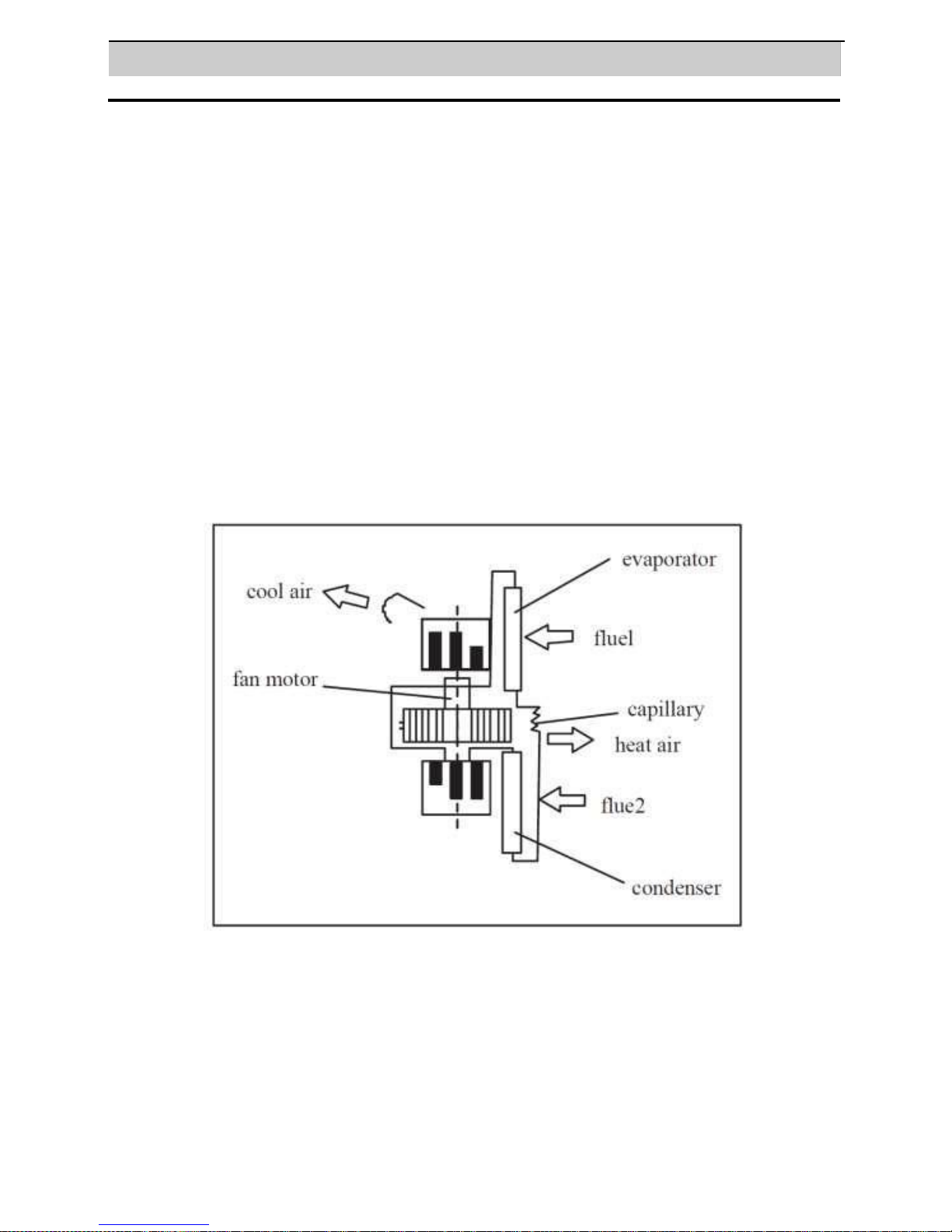
Under function of fan motor, indoor airflow changed into cooled air through
evaporator then blew out, while the indoor airflow changed into heated air though
condenser then blew out. There are 2 flues designed on structure of this unit:
heated air is discharged from rear air outlet vent on back air conditioner while
cooled air from front air outlet vent of the unit. After guide louver, gentle and steady
cooled airflow is produced to reach needed cooling effect.
Working principle
3
When only used as dehumidifier, remember
to take off heat discharge pipe from unit and
install it onto unit when the unit is used as
air conditioner. Since partial indoor air will
be heated
as heat air and discharged to outside by
discharge pipe after cycling then outdoor air
will enter to maintain balance air pressure,
thus the air conditioner will only lower
temperature of partial regional air of indoor
room instead of turning entire indoor air to a
lower temperature.
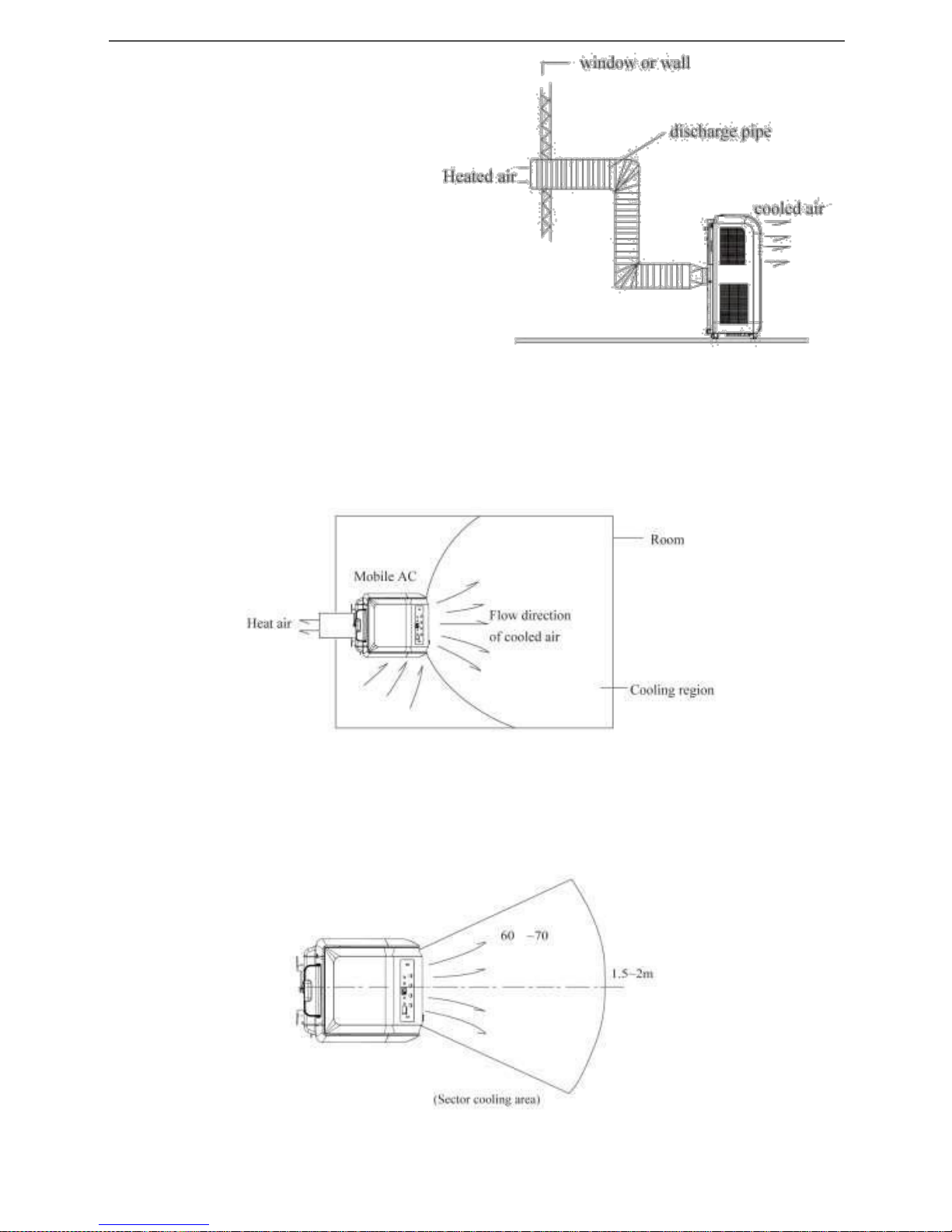
Usage Location
1. Where room area is smaller than 15m2, and wall (or building) has well heat insulation
effect. As shown in following figure, if unit is in shown location, the cooling effect will be
better.
2. If room area is larger than 20m2, for example workshop or factory, the unit can only offer
cooled air to partial area(as shown in following figure),and people in this area can enjoy
better cooling effect.
4
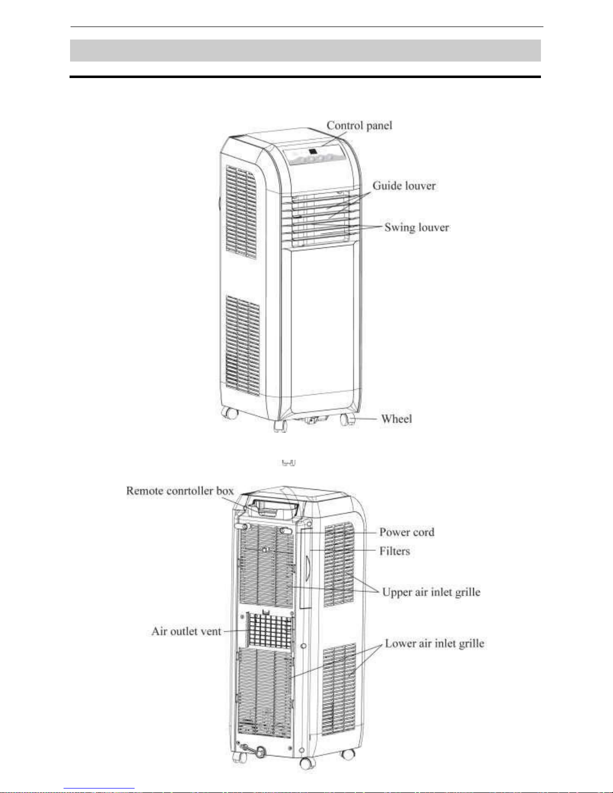
STRUCTU
RE
Front
Rear
5

OPERATING METHODS
Location Requirements Of The temp. range of this unit is
the Unit 16° C - 30°C
Unit Setup Place the unit on horizontal floor when using and maintain a
distance for above 50cm from walls, surface of flammable
objects or other obstructions.
Power Check before connecting power:
The normal running fluctuation range of voltage of the unit is
It is better to adopt power lead with pickup current above 10A to
prevent sudden drop of voltage when the unit is running.
It is necessary to exchange broken power hose by special
power hose. When it is necessary to change power hose or
maintain, please contact the seller and have them repaired by
professional personnel.
Earth must be conducted reliably and should connect to special
earthing equipments in building to ensure well earth.
Do not replace fuse by steel or copper and capacity for fuse
should be proper. It is forbidden to fix power on blade or sharp
objects to prevent creepage leaded by mangled wire.
Circuitry must be installed and fixed by professional personnel
following the national wiring regulations. Creepage protect
switch with enough capacity and 10A solenoid heat tripping air
switch must be contained in circuitry. It is forbidden to connect
earth wire to water pipe or gas pipe, plug off power plug or cut
off power supply when the unit is not going to be used.
6

Functions and operation methods of control panel
Panel Control
Under ON status, after each pressing of the button on control panel, the air conditioner will give out a sound.
Meanwhile, corresponding indicator on control panel will be bright. The display may be off during some mode
l. ON/OFF
Connect the power plug to the appropriate electrical socket
outlet. Press the ON/OFF button to turn the appliance ON.
Press the ON/OFF button again to turn the appliance
OFF. 2. "+","-" key
Under cooling mode, press “+” or “-” button to increase or decrease set temperature by
1°C. Set temperature is range is 16°C ~30°C. Under auto, drying or fan mode, this button
is invalid.
3. MODE
In the state of running, press the key to enter the mode of
COOL→DRY→FAN→AUTO. 4. " " Fan Mode
When working in FAN or COOL mode, the air conditioner can select 3 speeds using the
remote control and the initial speed is high; when running in DRY, fan motor runs in Low
speed.
5. " "Dry mode
When the unit running in the dry mode, it can decrease the humidity of the
room. 6. " "Cool mode
Under this mode, cooling mode indicator is lit. Temperature setting range is 16°C~30°C.
7. " "Water full
Lights up when tank is full, drain the condensate from the unit for the unit to function again.
7

Ambient temperature
Ambient Temperature range of the unit is 16°C - 30 °C.
Cool Mode
1 In the COOLING Mode the appliance must be placed close to a window or opening so
that the warm exhaust air can be ducted outside through the window.
2 Press ON / OFF to turn on unit, press MODE to select cool mode, which is indicated
with the “ ” light on and unit runs in cooling mode.
3 Press the + or – button on the unit or the remote to set the temperature between 16°C -
30 °C.
4 Press SPEED button on the remote to select proper fan speed (High/Medium/Low).
Compressor delay protection
Compressor switches OFF on changing modes before switching ON. Wait approximately
3 minutes and for compressor to restart. This prevents overheating of the compressor and
possible circuit breaker tripping. The fan will continue to run during this time.
Note
When in drying mode, indoor fan motor runs in low speed, compressor runs continuously,
set temperature will not be displayed and is not adjustable. Exhaust hose does not need.
FAN
Press “ON/OFF” to turn on unit and select FAN by SPEED, indoor fan motor can run in
3 speeds of High, Medium and low, set temperature will not be displayed and is not
adjustable, High, Medium or low symbol will be displayed in display window according
to speed of indoor fan.
8

Operation of wireless remote control
Names and functions of wireless remote control
Note: Be sure that there are no obstructions between receiver and remote controller; do not
drop or throw the remote control; do not let any liquid in the remote control or place the
remote control directly under the sunlight or any place where is very hot.
Remote Control
ON / OFF
ON / OFF button
On pressing this button, the unit will be turned ON, press it
once more, the unit will be turned OFF. When turning on or
turning off the unit, the Timer, Sleep function will be
cancelled, but the presetting time is still remained.
MODE
MODE button
Press this button, Auto, Cool, Dry, Fan, can be selected
circularly. Auto mode is default setting when the unit is
switched on. Under Auto mode, the temperature will not
be displayed
SWING
SWING button
Press this key to activate or deactivate the swing. ( This
Function is not available in this model )
FAN
FAN button
By pressing this key, you may select AUTO, FAN 1, FAN 2
or FAN 3 mode. This lets the speed of the fan be set. AUTO
is default setting. Only LOW fan speed can be set under
DRY mode.
SLEEP
SLEEP button
On pressing this button, Sleep On and Sleep Off can be selected.
After powered on, Sleep Off is defaulted. In this mode the
selected temperature will increase by 1 °C every 1 hour for 2
hours and the temperature totally increased by 2°C and will
continue in this mode until the temperature is changed or the unit
is switched OFF
Note: This feature is unavailable under FAN or DRY modes.
9

Remote
Control
+ button
Can be used to set Temperature / Timer functions
Pressing this button will increase the temperature in
the cool mode. On pressing and holding this button
for more than 2 seconds, the units will increase rapidly
until the button is released, On releasing the button
the setting is applied after a beeping sound is
produced. In Auto mode, the temperature cannot be
set, but pressing this button will make a beeping
sound. Operating temperature range is 16℃ - 30℃.
Timer
TIMER button
- You can set both pre-set stop and delayed start while unit is in
ON position or OFF position.
When unit is in ON position, first press TIMER button to go to
Pre-set stop setting, then “T-OFF” light will illuminate, tap or hold
the + button or the - button to change delay stop timer at 0.5 hour
increments up to 24 hours. Then press the TIMER button to
confirm the setting (the control will confirm the setting
automatically after 5 seconds) and go to delay start setting.
Use the same way as above to set the delay start timing. If you
don’t need to set delay start, press the TIMER button again to
exit. After 2 seconds, the control will automatically change the
display back to previous temperature display. If you want to check
remain timing, press the TIMER button. The delay start operation
automatically selects mode, temperature and fan speed the same
as last operation you set.
When unit is in OFF position, press TIMER button will first go to
delay start setting, then “T-ON” light will illuminate, set the delay
start and delay stop timing the same way as above.
To cancel the timer setting, simply tap Timer button to cancel and
the timer setting will be cancelled. This can be confirmed by
noticing that the T-ON and T-OFF arrow will disappear.
- button
Can be used to set Temperature / Timer functions
Pressing this button will decrease the temperature in
the cool mode. On pressing and holding this button
for more than 2 seconds, the units will decrease
rapidly until the button is released, On releasing the
button the setting is applied after a beeping sound is
produced. In Auto mode, the temperature cannot be
set, but pressing this button will make a beeping
sound. Operating temperature range is 16℃ - 30℃
10

Guide for operation- General operation
1. After powered on, press ON/OFF button, the unit will start to
run.
2. Press MODE button, select desired running mode,
3. Pressing + or - button, to set the desired temperature. (It is
not possible to set the temp. at AUTO mode.)
4. Pressing FAN button, set fan speed, can select AUTO, FAN
1, FAN 2 or FAN 3.
5. Pressing SWING button, to select the swing. (This function is
unavailable for this model).
Guide for operation- Optional operation
1. Press SLEEP button, to set the unit to sleep mode.
2. This function can be cancelled on pressing the sleep button
again when the unit is on sleep mode.
2. Press TIMER button, can set the scheduled timer on or timer
off. ( Please refer to the operation of the wireless remote on
instructions to use the timer function )
Changing Batteries
1. Place the remote face down on a flat surface
2. Unclip the battery cover and remove the cover.
3. Take out the old batteries. (As show in figure)
4. Insert two new AAA1.5V dry batteries, and pay attention to
the polarity. (As show in figure)
4. Attach the back cover of wireless remote control.
★ NOTE:
● When changing the batteries, do not use the old or different
batteries, it may cause malfunction of the wireless remote
control.
● If the wireless remote is not used for a long time, please take
the batteries out to check for leakage, do not let the leakage
liquid damage the wireless remote control.
● The remote should be in the unit’s operating range and
directed towards the sensor on the unit.
● It should be placed at where is 1m away from the TV set or
stereo sound sets.
● If the wireless remote control can not operate normally, please
take them out, after 30s later and reinsert, if they cannot
normally run, please change them.
11

DRAINAGE METHOD
During the process of cooling or drying, excess condensation will occur inside the unit, although the water
will be evaporated by the coil for maximum efficiency. In very warm temperature or high humidity condition,
it will require water drainage. When the internal water tank is full the buzzer will beep 8 times as a warning,”
“water full indicator will light up on the panel with H8 displayed on LED display window and the unit will
stop working. For the unit to resume operation water should be drained out of the unit from the drainage
hose. Remove the drain hose from the clamp and release the excess water at downward slope by removing
the rubber plug. The unit will resume running when the water is completely drained from the unit out of the
hose or the drain port.
INSTALLATION OF DRAINAGE HOSE
Note: The drainage hose must be installed before operating the unit otherwise a blockage may occur
affecting the normal operation of the unit.
- Drain Hose included:
- Installation of Drain Hose
1. Remove drain cap (B) from drain port (A).
12

2. Attach the drain hose clamp (C) to the back panel of the air conditioner near the drain port
(A) with the screw provided.
3. Attach one end of the drain hose (D) to the drain port (A) with the clip (E). Make sure the
hose is fully inserted into the drain port (A).
4. Insert the rubber plug (F) into the other end of the drain hose (D) and secure with clip (E).
5. Snap the free end of the drain hose (D) into the drain hose clamp (C).
13

ACCESSORIES AND INSTALLATION OF HEAT EXHAUST HOSE
Installation of the Exhaust Hose and Adapter
1. Position the Air conditioner to its required location. See “Location Requirements.”
2. Insert one end of the flexible exhaust hose into the exhaust adapter.
3. Twist clockwise to lock hose into place.
4. Insert the other end of the flexible exhaust hose into the window exhaust adapter.
5. Twist clockwise to lock hose into place.
A
B
C
● Length of the exhaust pipe should be ranging from 500mm-1500mm. It is recommended
to use it with shortest length.
● When installing the exhaust pipe, it should be as straight as possible. Don't extend the
pipe or connect it with other exhaust pipe as it may cause damage to the unit.
Correct installation is as shown in figure (When installing it on wall, position of the hole
should be about 40cm - 130cm from the floor).
14

If the pipe are to be bent, please install it by following the requirements shown in the picture
below.
An example of an improper installation is shown in following figure (If the pipe is bent too
much, it would easily cause malfunction.)
15

Maintenance
Mobile AC
Warning
Clean air filter
Note:
Clean AC
There are wheels at bottom of mobile air conditioner that enable the unit moves among
rooms conveniently according to need.
Plug off power plug from socket and cut off power before any maintenance to prevent
creepage.
If too much dust is deposed on the filter, performance of air conditioner will reduce, thus
it is better to clean filter at least once every 2 weeks.
Disassembly
- From these two direction to take out filters.
Wash
- Clean filter individually, When cleaning, wash the filter by soaking it in warm soap water
then dry it.
Please soak the cloth in lukewarm water (or Soap water or water with proper cleaner)
and wipe the dirty part on unit slightly after the cloth is wrung. Don’t clean the unit by
gasoline, diesel oil or other flammable liquids.
Pull out the power plug before cleaning.
16

MALFUNCTION ANALYSIS
If a malfunction occurs, please check the following before maintenance:
Troubles
Possible Causes
Solutions
The air conditioner
The power supply is not
1. Insert the power plug tightly.
doesn't start.
connected well. The power plug
2. Replace the power plug or
is not inserted tightly. There is
socket.
the malfunction of power plug
3. Have an electrician replace the
or socket.
fuse.
The fuse is broken.
The LCD displays the
Is the TIMER ON in
Cancel the "SET TIMER"
number of time, but it
operation?
operation or to wait the auto
doesn't work.
running.
Although it was set to
1. The room temp is
1. This is the normal phenomenon.
COOL mode, there is no
lower than the set
2. Unit is running in defrosting
cool air.
temp.
operation, it will resume running in
2. The evaporator frosts.
original operation after
defrosting.
Although it was set the
1. The evaporator frosts.
1. Unit is running in defrosting
DRY mode, there is no
operation, it will resume running in
cool wind.
original operation after
defrosting.
The LCD displays "
".
1. Low voltage over
1. Cut off power supply, after
current protection.
10 minutes, turn on the unit, if
"
" still be displays, please
contact your dealer for technical
advice.
The LCD displays "
".
The water tank gets full.
1. Check the drainage hose is
installed correctly
2. Check unit is on an even
level surface.
3. Drain excess water via the
drainage hose at a
downward slope with no
sharp bends.
17

SAFE NOTE AND NOTICE
Location - Don't place the unit in narrow location. Ensure better ventilation for unit to
prevent malfunction occurs.
- Don't place the unit in direct sunlight as it may reduce of effect of cooling.
- The unit should be at least 50cm away from surface of flammable thing.
- Don't soak the unit or operate it in place where is easy to get wet to prevent
creepage.
- Don't operate the unit in following location for malfunction may be led:
*Gas place *Fire *where is easy to get oil.
Others: Consider safe problem to following people.
1)Children and patients
2)Sick people or who cannot express himself or herself
3) Those who are exhausted, badly drunk or taken lot of soporific.
- Don't climb on the unit or place something on it for drop may occur and leading
malfunction.
- Don't let wind blows to human directly for long time for it is not good for health.
- The unit should leave TV for at least lm to prevent disturbance of
electromagnetic wave.
- Don't block air inlet or outlet vent for it would lead malfunction.
- Don't insert finger or stick into air outlet vent; take special care to children to
prevent accidents.
- It is forbidden to slope or turn down air conditioner. Take off power plug
immediately if abnormal circumstance occurs and contact the authorized seller for
check and repair.
- Don't sprinkle and shower unit by insecticide for it will lead deformation or
breakage
- If your air conditioner has problems on quality or others, please contact local
seller.
18
Electrical products should not be disposed of with general household waste. Please
recycle where facilities exist.
For more information on disposal contact your local authority

FAULT CHECK LIST
The air conditioner does not run Is the air conditioner plugged in?
Is there a power failure?
Is the ‘WATER FULL’ indicator flashing?
Is the room temperature below the set temperature?
The machine seems to do little
The machine seems to
do nothing.
Is there direct sunshine? (Please put down the curtain.)
Are too many windows or doors open?
Are there too many people in the room?
Is there something in the room producing lots of heat?
Is the filter dusty, contaminated?
Is the air intake or output blocked up?
Is the room temperature below your selected
temperature?
Too noisy
Is the machine positioned unevenly so as to
create vibration?
Is the floor underneath the machine uneven?
The compressor doesn’t run.
Is so, it is possible the overheat protection of the compressor
is on. Just wait for the temperature to drop.
☆ Never try to repair or dismantle the unit yourself
19

ONE (1) YEAR LIMITED WARRANTY
SAVE THIS WARRANTY INFORMATION
Georges Industrial Services Ltd guarantees this product free from defects in
materials and workmanship for a period of one (1) year from the date of
purchase, limited to parts only.
Faults arising from a faulty installation is specifically excluded.
This unit must be operated under conditions as recommended, at voltages
indicated on the unit. Any attempts made to service or modify the unit by
unqualified technician, will render this WARRANTY VOID. The actual
product may differ slightly from the illustration. This warranty is in addition to,
and does not affect, your statutory rights.
If the unlikely event of a fault, the appliance must be returned to the point of sale
with proof of purchase and a FULL description of the fault
In the unlikely event of a problem, please contact our help desk 0208 207
2455
We recommend that you note the details of your purchase below and retain
your original proof of purchase receipt with this manual. Keep these
documents safe in the event of a warranty claim.
Date of purchase: _____________________________
Purchased from (Dealer Name): _____________________________
Retailer name: _____________________________
Model number: _____________________________
Serial number: _____________________________
Date of installation: _____________________________
20
 Loading...