

C1VI - 18 / C1VO - 18
C1VI - 24 / C1VO - 24

Table of Contents
Summary and Features
1.Safety Precautions
2.Specifi cations
2.1 Unit Specifi cations
2.2 Operation Characteristic Curve
2.3 Capacity Variation Ratio According to Temperature
2.4 Operation Data
2.5 Noise Criteria Curve Tables for Both Models
3. Construction Views
3.1 Indoor Unit
3.2 Outdoor Unit
4. Refrigerant System Diagram
5. Schematic Diagram
5.1 Electrical Data
5.2 Electrical Wiring
5.3 Printed Circuit Board
6. Function and Control
6.1 Remote Control Operations
6.2 Description of Each Control Operation
7. Installation Manual
7.1 Notices for Installation
7.2 Installation Dimension Diagram
7.3 Install Indoor Unit
7.4 Install Outdoor Unit
7.5 Check After Installation and Test Operation
7.6 Installation and Maintenance of Healthy Filter
..........................................................................
1
................................................................................2
...........................................................................................3
.....................................................................................3
.................................................................7
..................................8
..........................................................................................8
............................................9
............................................................................10
...............................................................................................10
............................................................................................11
.........................................................12
............................................................................13
..........................................................................................13
.......................................................................................13
................................................................................16
........................................................................19
.....................................................................19
....................................................22
.............................................................................29
.............................................................................29
...............................................................31
.....................................................................................32
..................................................................................33
.............................................34
.........................................35

8. Exploded Views and Parts List
8.1 Indoor Unit
8.2 Outdoor Unit
9. Troubleshooting
9.1 Precautions before Performing Inspection or Repair
9.2 Confi rmation
9.3 Flashing LED of Indoor/Outdoor Unit and Primary Judgement
9.4 How to Check simply the main part
10. Removal Procedure
10.1 Removal Procedure of Indoor Unit
10.2 Removal Procedure of Outdoor Unit
....................................................
36
..............................................................................................36
...........................................................................................40
...................................................................................44
...............................44
............................................................................................45
...............45
.........................................................50
.........................................................................70
.........................................................70
......................................................79

Summary and Features
1
Outdoor Unit
C1VI18
C1VI-24
YB1FA
Remote Controller
C1VI-18
C1VI-24
Summary and Features
Indoor Unit
Safety Precautions
2
Caution
Warning
Warning
Caution
could result in
personal injury
or death.
Incorrect handling
result in
injury
, or damage to product
or property.
Incorrect handling
may
minor
Recognize the following safety information:
Installing, starting up, and servicing air conditioner can be
hazardous due to system pressure, electrical components, and
equipment location, etc.
Only trained, qualified installers and service personnel are
allowed to install, start-up, and service this equipment.
Untrained personnel can perform basic maintenance functions
such as cleaning coils. All other operations should be performed
by trained service personnel.
When handling the equipment, observe precautions in the
manual and on tags, stickers, and labels attached to the equipment. Follow all safety codes. Wear safety glasses and
work gloves. Keep quenching cloth and fire extinguisher nearby
when brazing.
Read the instructions thoroughly and follow all warnings or
cautions in literature and attached to the unit. Consult local
building codes and current editions of national as well as local
electrical codes.
All electric work must be performed by a licensed technician
according to local regulations and the instructions given in this
manual.
Never supply power to the unit unless all wiring and tubing
are completed, reconnected and checked.
This system adopts highly dangerous electrical voltage.
Incorrect connection or inadequate grounding can cause
personal injury or death. Stick to the wiring diagram and all
the instructions when wiring.
Have the unit adequately grounded in accordance with
local electrical codes.
Have all wiring connected tightly. Loose connection may
lead to overheating and a possible fire hazard.
All installation or repair work shall be performed by your dealer
or a specialized subcontractor as there is the risk of fire, electric
shock, explosion or injury.
Make sure the ceiling wall is strong enough to bear the
weight of the unit.
Make sure the noise of the outdoor unit does not disturb
neighbors.
Properly insulate any tubing running inside the room to
prevent the water from damaging the wall.
Make sure the outdoor unit is installed on a stable, level
surface with no accumulation of snow, leaves, or trash
beside.
Follow all the installation instructions to minimize the risk
of damage from earthquakes, typhoons or strong winds.
Avoid contact between refrigerant and fire as it generates
poisonous gas.
Apply specified refrigerant only. Never have it mixed with
any other refrigerant. Never have air remain in the
refrigerant line as it may lead to rupture and other hazards.
Make sure no refrigerant gas is leaking out when
installation is completed.
Should there be refrigerant leakage, the density of
refrigerant in the air shall in no way exceed its limited
value, or it may lead to explosion .
Before installing, modifying, or servicing system, main
electrical disconnect switch must be in the OFF position.
There may be more than 1 disconnect switch. Lock out and
tag switch with a suitable warning label.
Keep your fingers and clothing away from any moving parts.
Clear the site after installation. Make sure no foreign
objects are left in the unit.
Always ensure effective grounding for the unit.
Never install the unit in a place where a combustible gas
might leak, or it may lead to fire or explosion.
Make a proper provision against noise when the unit is
installed at a telecommunication center or hospital.
Provide an electric leak breaker when it is installed in a
watery place.
Never wash the unit with water.
Handle unit transportation with care. The unit should not be
carried by only one person if it is more than 20kg.
Never touch the heat exchanger fins with bare hands.
Never touch the compressor or refrigerant piping without
wearing glove.
Do not have the unit operate without air filter.
Should any emergency occur, stop the unit and disconnect
the power immediately.
1.Safety Precautions
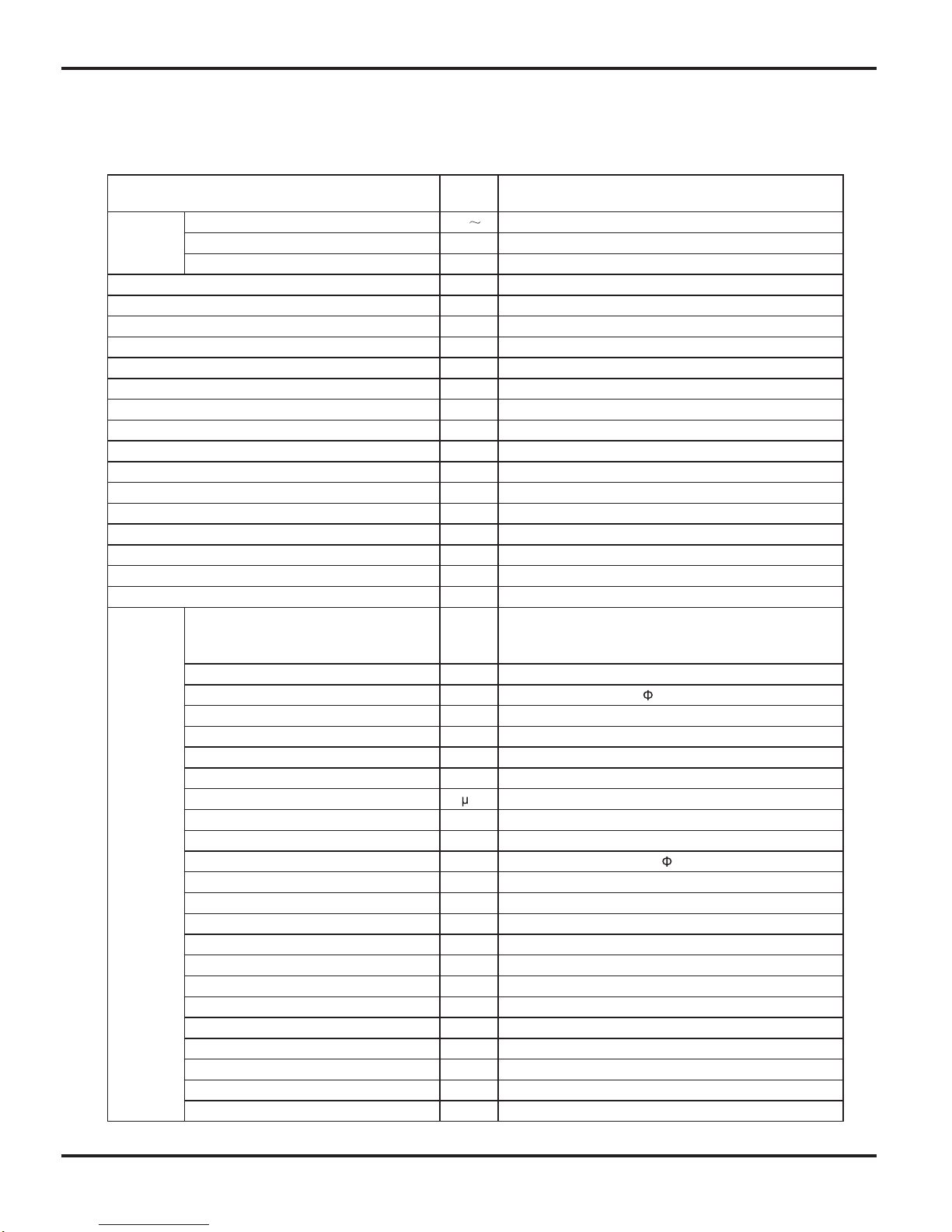
Specifi cations
3
Model
C1VI-18 / C1VO-18
Power
Supply
VegatloV detaR
220-240
05zHycneuqerF detaR
Phases 1
Power Supply Mode Outdoor
)0066~0621(5725WyticapaC gnilooC
)0086~0211(0585WyticapaC gnitaeH
)0562~083(0061WtupnI rewoP gnilooC
)0562~053(0261WtupnI rewoP gnitaeH
52.7AtnerruC rewoP gnilooC
43.7AtnerruC rewoP gnitaeH
0562WtupnI detaR
00.21AtnerruC detaR
m )LS/L/M/H/HS(emuloV wolF riA
3
-/055/056/087/058h/
2h/LemuloV gniyfidimuheD
03.3W/W REE
16.3W/W POC
/W/W REES
/W/W FPSH
maerA noitacilppA
2
23-34
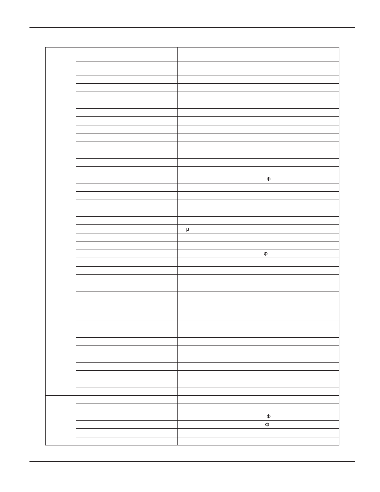
Indoor Unit
Model of indoor unit C1VI-18
wo fl-ssorCepyT naF
mm )LXD(htgneL retemaiD
98X710
Fan Motor Cooling Speed(SH/H/M/L/SL) r/min 1350/1200/1050/900/Fan Motor Heating Speed(SH/H/M/L/SL) r/min 1420/1250/1150/1050/-
02WrotoM naF fo tuptuO
52.0AALR rotoM naF
Fan Motor Capacitor
5.1F
-WretaeH fo tupnI
ebuT reppoc-niF munimulA mroF rotaropavE
mmretemaiD epiP
7
4.1-2mmpaG n fi-woR
8.403X4.52X517mm )WXDXL( htgneL lioC
BV82PMledoM rotoM gniwS
3W rotoM gniwS fo tuptuO
A51.3 BCPA esuF
-/53/04/64/84 )A( Bd )LS/L/M/H/HS( leveL erusserP dnuoS
-/54/05/45/85 )A( Bd )LS/L/M/H/HS( leveL rewoP dnuoS
002X892X049mm )DXHXW( noisnemiD
083X582X0101mm)H/W/L( xoB notraC fo noisnemiD
003X383X3101mm )H/W/L(egakcaP fo noisnemiD
21gk thgieW teN
61gkthgieW ssorG
2.Specifications
2.1 Unit Specifi cations
Specifi cations
4
Outdoor
Unit
C1VO-18tinU roodtuO fo ledoM
Compressor Manufacturer/Trademark MITSUBISHI ELECTRIC (GUANGZHOU)COMP
CMYGF031BNSledoM rosserpmoC
S05VPliO rosserpmoC
yratoRepyT rosserpmoC
00.72A .A.R.L
04.8A ALR rosserpmoC
5421WtupnI rewoP rosserpmoC
8756-L11TN1rotcetorP daolrevO
yrallipaCdohteM gnilttorhT
03~61CºpmeT noitarepO
54~81Cº)gnilooC( pmeT tneibmA
42~51- Cº)gnitaeH( pmeT tneibmA
ebuT reppoc-niF munimulA mroF resnednoC
mm retemaiD epiP
7
4.1-2mmpaG n fi-swoR
055X1.83X218mm )WXDXL( htgneL lioC
088mprdeepS rotoM naF
06WrotoM naF fo tuptuO
26.0A ALR rotoM naF
Fan Motor Capacitor
5.3F
Air Flow Volume of Outdoor Unit m
3
0042h/
wo fl-laixAepyT naF
mmretemaiD naF
445
gnitsorfeD citamotuAdohteM gnitsorfeD
1TepyT etamilC
Isolation I
42PInoitcetorP erutsioM
Permissible Excessive Operating Pressure
for the Discharge Side
0.3aPM
Permissible Excessive Operating Pressure
for the Suction Side
9.0aPM
-/-/45 )A( Bd )L/M/H( leveL erusserP dnuoS
-/-/46 )A( Bd )L/M/H( leveL rewoP dnuoS
873X695X998mm )DXHXW( noisnemiD
036X714X549mm)H/W/L( xoB notraC fo noisnemiD
336X234X849mm )H/W/L(egakcaP fo noisnemiD
83gk thgieW teN
34gkthgieW ssorG
A014R tnaregirfeR
02.1gkegrahC tnaregirfeR
Connection
Pipe
5mhtgneL
03m/gegrahC lanoitiddA saG
Outer Diameter Liquid Pipe mm
6
Outer Diameter Gas Pipe mm
12
01mthgieH ecnatsiD xaM
03mhtgneL ecnatsiD xaM
The above data is subject to change without notice. Please refer to the nameplate of the unit.
Specifi cations
5
Model
C1VI-24 / C1VO-24
Power
Supply
VegatloV detaR
220-240
05zHycneuqerF detaR
1sesahP
roodtuOedoM ylppuS rewoP
)0007~0041(0546WyticapaC gnilooC
)0028~0021(0007WyticapaC gnitaeH
)0052~053(5891WtupnI rewoP gnilooC
)0072~053(0391WtupnI rewoP gnitaeH
08.8AtnerruC rewoP gnilooC
65.8AtnerruC rewoP gnitaeH
0072WtupnI detaR
04.21AtnerruC detaR
m )LS/L/M/H/HS(emuloV wolF riA
3
-/055/007/008/009h/
2h/LemuloV gniyfidimuheD
52.3W/W REE
26.3W/W POC
/W/W REES
/W/W FPSH
maerA noitacilppA
2
27-42
Indoor Unit
Model of indoor unit
C1VI-24
wo fl-ssorCepyT naF
Diameter Length(DXL) mm
98X765
Fan Motor Cooling Speed(SH/H/M/L/
SL)
r/min 1250/1100/950/800/-
Fan Motor Heating Speed(SH/H/ML/
SL)
r/min 1300/1100/1000/850/-
53WrotoM naF fo tuptuO
03.0AALR rotoM naF
Fan Motor Capacitor
5.2F
-WretaeH fo tupnI
ebuT reppoc-niF munimulA mroF rotaropavE
mmretemaiD epiP
7
5.1-2mmpaG n fi-woR
9.243X4.52X567mm )WXDXL( htgneL lioC
XX53PMledoM rotoM gniwS
3W rotoM gniwS fo tuptuO
A51.3 BCPA esuF
-/93/24/74/15 )A( Bd )LS/L/M/H/HS( leveL erusserP dnuoS
-/94/25/75/16 )A( Bd )LS/L/M/H/HS( leveL rewoP dnuoS
912X513X7001mm )DXHXW( noisnemiD
313X593X3701mm)H/W/L( xoB notraC fo noisnemiD
823X893X6701mm )H/W/L(egakcaP fo noisnemiD
41gk thgieW teN
91gkthgieW ssorG
Specifi cations
6
Outdoor
Unit
C1VO-24tinU roodtuO fo ledoM
Compressor Manufacturer/Trademark MITSUBISHI ELECTRIC (GUANGZHOU)COMP
CMYGF031BNSledoM rosserpmoC
S05VPliO rosserpmoC
yratoRepyT rosserpmoC
00.72A .A.R.L
04.8A ALR rosserpmoC
5421WtupnI rewoP rosserpmoC
8756-L11TN1rotcetorP daolrevO
yrallipaCdohteM gnilttorhT
03~61CºpmeT noitarepO
54~81Cº)gnilooC( pmeT tneibmA
42~51- Cº)gnitaeH( pmeT tneibmA
ebuT reppoc-niF munimulA mroF resnednoC
mm retemaiD epiP 7
4.1-2mmpaG n fi-swoR
066X1.83X738mm )WXDXL( htgneL lioC
005/096mprdeepS rotoM naF
06WrotoM naF fo tuptuO
26.0A ALR rotoM naF
Fan Motor Capacitor
5.3F
Air Flow Volume of Outdoor Unit m
3
0023h/
wo fl-laixAepyT naF
mmretemaiD naF
520
gnitsorfeD citamotuAdohteM gnitsorfeD
1TepyT etamilC
InoitalosI
42PInoitcetorP erutsioM
Permissible Excessive Operating
Pressure for the Discharge Side
0.3aPM
Permissible Excessive Operating
Pressure for the Suction Side
9.0aPM
-/-/45 )A( Bd )L/M/H( leveL erusserP dnuoS
-/-/46 )A( Bd )L/M/H( leveL rewoP dnuoS
693X007X559mm )DXHXW( noisnemiD
537X554X6201mm)H/W/L( xoB notraC fo noisnemiD
057X854X9201mm )H/W/L(egakcaP fo noisnemiD
84gk thgieW teN
35gkthgieW ssorG
A014R tnaregirfeR
53.1gkegrahC tnaregirfeR
Connection
Pipe
5mhtgneL
03m/gegrahC lanoitiddA saG
Outer Diameter Liquid Pipe mm
6
Outer Diameter Gas Pipe mm
12
01mthgieH ecnatsiD xaM
03mhtgneL ecnatsiD xaM
The above data is subject to change without notice. Please refer to the nameplate of the unit.
Specifi cations
7
gnitaeHgnilooC
0 10 20 30 40 50 60 70 90 0 10 20 30 40 50 60 70 80 90 100 120110
80
11
10
9
8
7
6
5
4
3
2
1
0
Compressor speed (rps)
)A(tnerruC
11
10
9
8
7
6
5
4
3
2
1
0
Compressor speed (rps)
)A(tnerruC
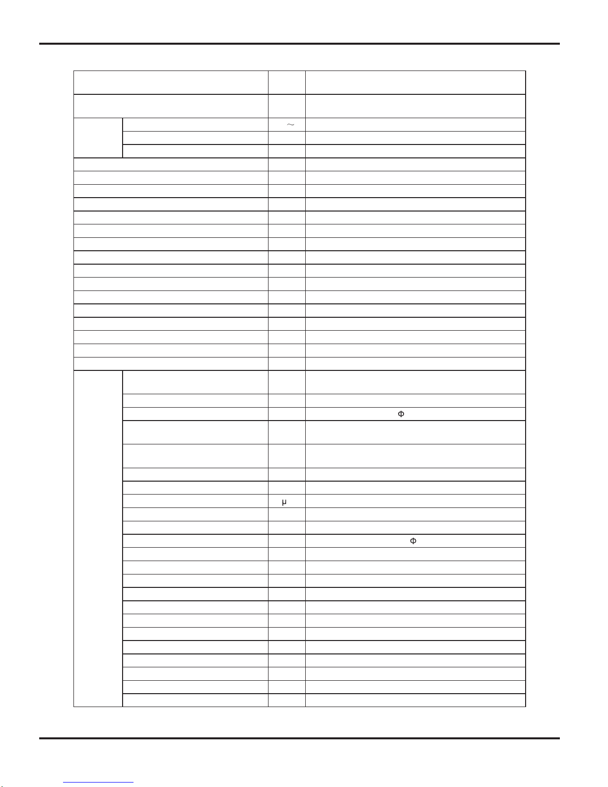
• Conditions
Indoor : DB26.7˚C/WB19.4˚C
Outdoor: DB35˚C/WB23.9˚C
Indoor air flow: Turbo
Pipe length : 5m
• Conditions
Indoor : DB21.1˚C/WB15.6˚C
Outdoor: DB8.33˚C/WB6.11˚C
Indoor air flow: Turbo
Pipe length : 5m
220V
230V
240V
220V
230V
240V
0 10 20 30 40 50 60 70 90 0 10 20 30 40 50 60 70 80 90 100 120110
80
11
10
9
8
7
6
5
4
3
2
1
0
Compressor speed (rps)
)A(tnerruC
11
10
9
8
7
6
5
4
3
2
1
0
Compressor speed (rps)
)A(tnerruC
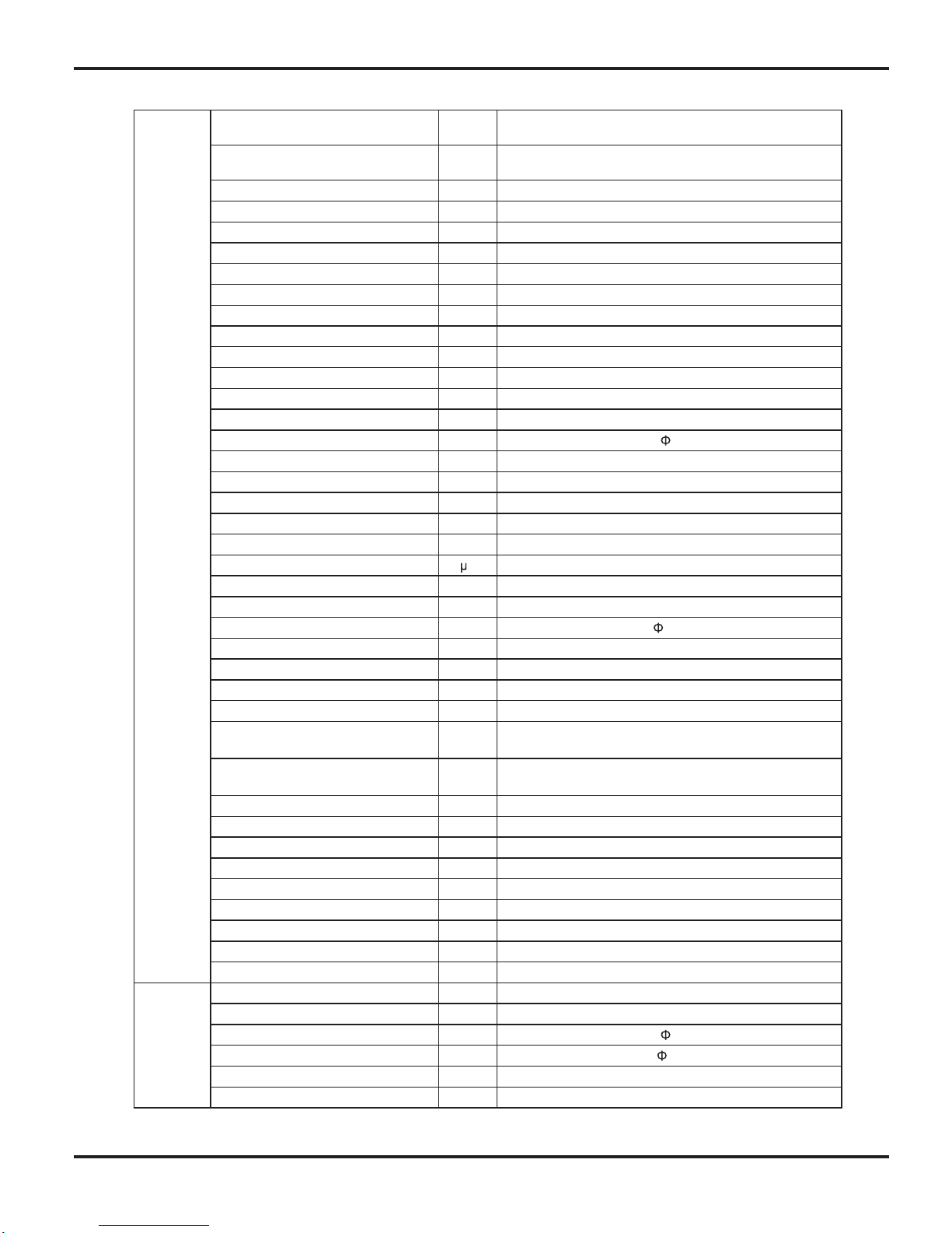
• Conditions
Indoor : DB26.7˚C/WB19.4˚C
Outdoor: DB35˚C/WB23.9˚C
Indoor air flow: Turbo
Pipe length : 5m
• Conditions
Indoor : DB21.1˚C/WB15.6˚C
Outdoor: DB8˚C/WB6.11˚C
Indoor air flow: Turbo
Pipe length : 5m
220V
230V
240V
220V
230V
240V
gnitaeHgnilooC
2.2 Operation Characteristic Curve
18K
24K
Specifi cations
8
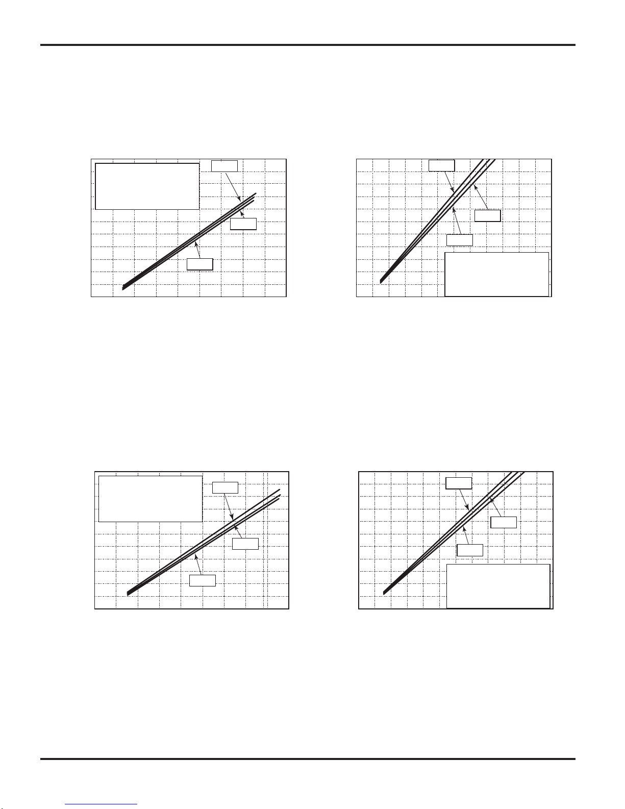
2.3 Capacity Variation Ratio According to Temperature
NOTES :
(1) T1: Inlet and outlet pipe temperature of evaporator
T2: Inlet and outlet pipe temperature of condenser
P: Pressure of air pipe connecting indoor and outdoor units(on the side of gas pipe)
(2) Measure surface temperature of heat exchanger pipe around center of heat exchanger path U bent.
(Thermistor themometer)
(3)
Connecting piping condition : 5 m
t n i looC a e H ig n g
3 2 3 3 3 4 3 5 3 6 3 7 3 8 3 9 4 3 –1 5
–10
5 0 5 7 10
4 0 4 1 42
100
105
95
90
85
80
75
70
65
60
55
50
Outdoor tem p . (˚C)
) %
(
o i t a r y t i c a p a C
110
100
90
80
70
60
50
40
Outdoor tem p . (˚C)
) % ( o i t a r y t i c a p a C
Conditions
Indoor:DB21.1
o
C /WB15.6 oC
Indoor air flow:Turbo
Pipe length:5m
Conditions
Indoor:DB26.7
o
C /WB19.4 oC
Indoor air flow:Turbo
Pipe length:5m
Cooling
Heating
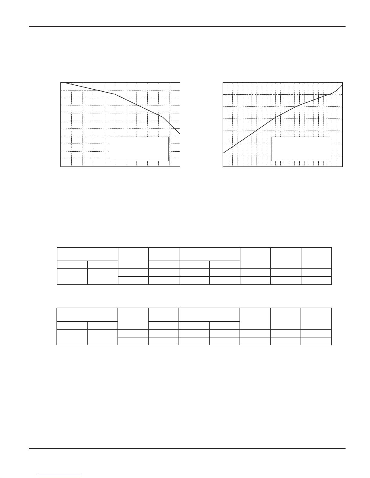
Standard
pressure
Indoor Outdoor
P (MPa)
T1 (°C) T2 (°C)
18K 0.9 to 1.1 12 to 14 70 to 42 High High 62
24K 0.8 to 1.0 10 to 12 70 to 40 High High 78
Outdoor fan
mode
Compressor
Frequency
(Hz)
26.7/19.4 35/–
(°C)
Model
name
temp.
Indoor fan
mode
Standard
pressure
Indoor Outdoor
P (MPa)
T1 (°C) T2 (°C)
18K 2.2 to 2.4 70 to 37 2 to 4 High High 62
24K 2.5 to 2.7 70 to 37 0 to 3 High High 80
Outdoor fan
mode
21.1/
–
8/6.11
Temperature condition
Temperature condition
(°C)
Model
name
Heat exchanger pipe
Heat exchanger pipe
temp.
Indoor fan
mode
Compressor
Frequency
(Hz)
2.4 Operation Data

Specifi cations
9
2.5 Noise Criteria Curve Tables for Both Models
Indoor side noise when blowing
Outdoor side noise
18K
24K
60
60
60 80 100
50
50
40
40
40
30
30
20
20
20
10
0
0
Indoor Fan Motor Rotating Speed
Noice/dB(A)
low
Middle
High Super High
Compressor frequency/Hz
)A(Bd/esioN
18 24K
Constrction Views
10
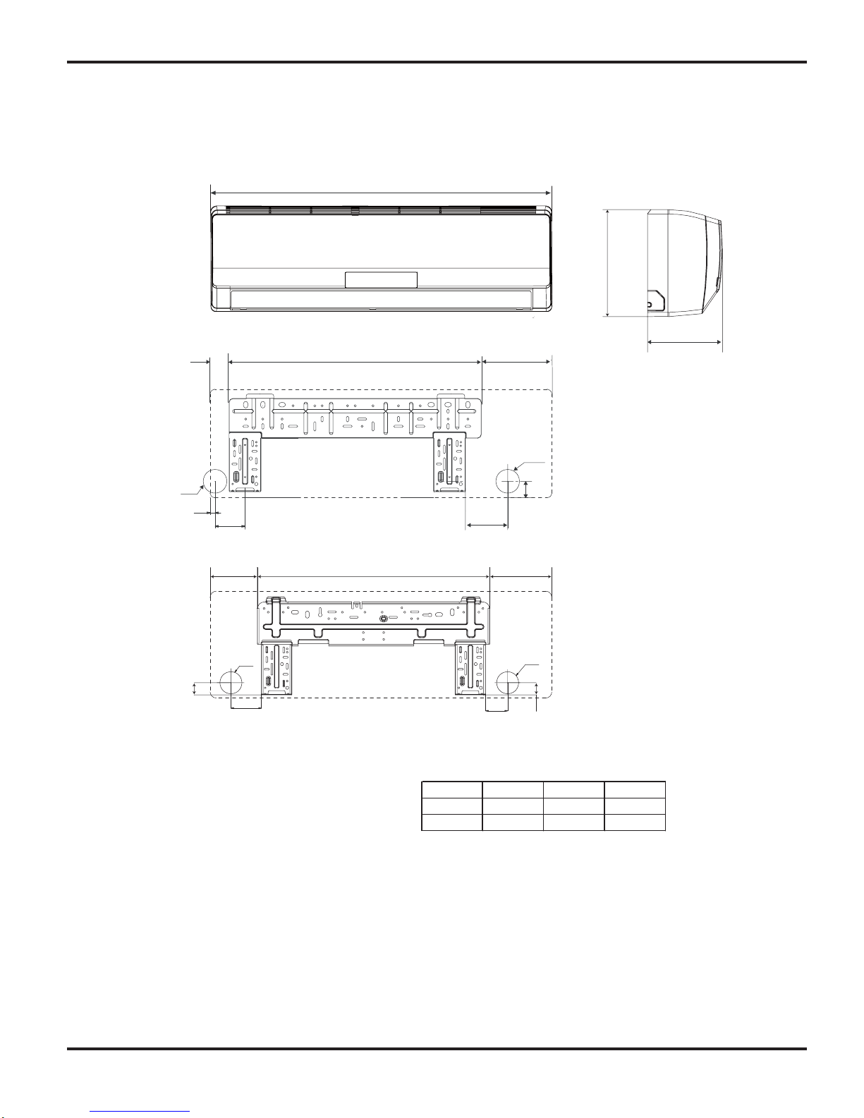
3. Construction Views
3.1 Indoor Unit
139
685
183
Φ55
Φ55
6 3
6 3
90
65
72
45
694
194
D
52
Φ55
Φ55
14
82
18K
24K
Model W H D
W
18K 940 298 200
24K 1007 315 219
Unit:mm
H
Constrction Views
11
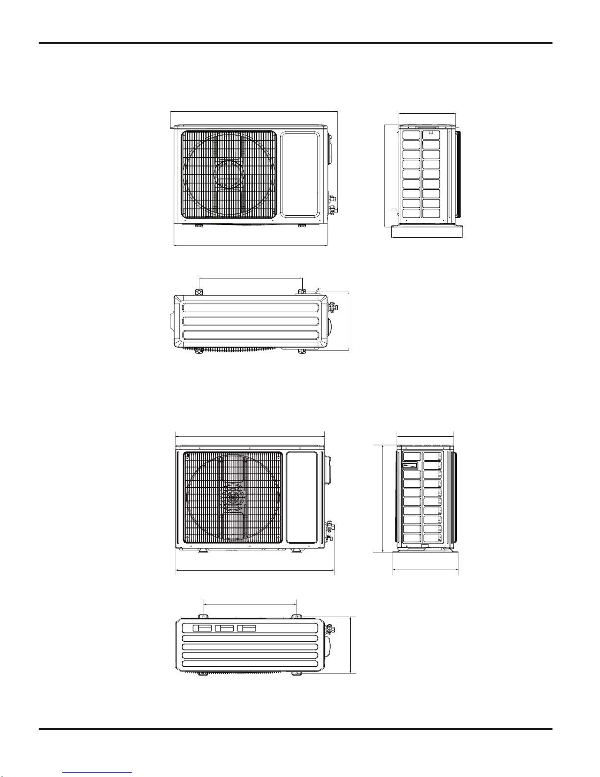
3.2 Outdoor Unit
18K
24K
955
560
043 798
396
3 6 4
7 0 0
899
818
695
378
303
343
550
Refrigerant System Diagram
12
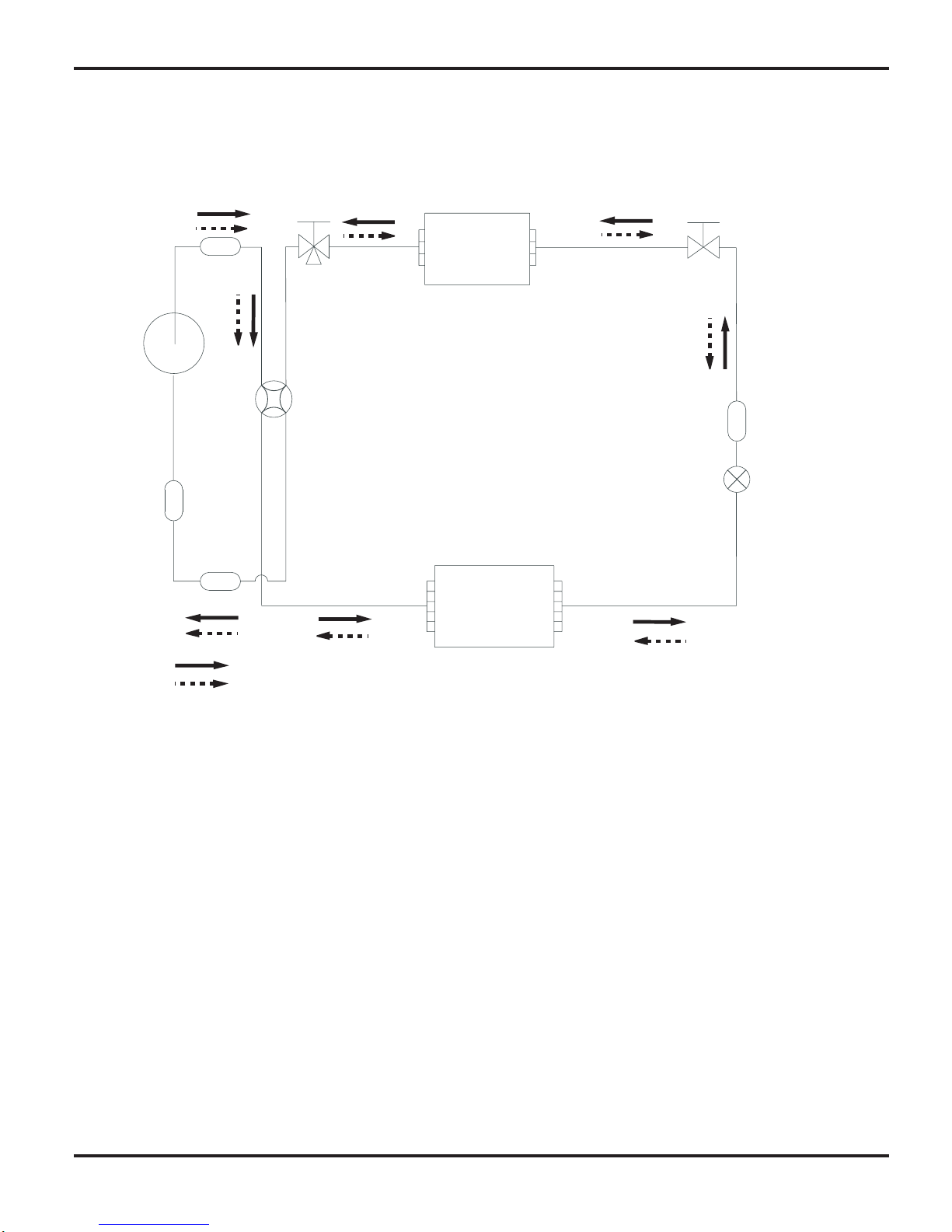
4. Refrigerant System Diagram
Refrigerant pipe diameter
Liquid :1/4" (6 mm)
Gas : 1/2" (12mm)
2-Way
valve
Strainer
Strainer
3-Way
valve
Muffler
4-Way valve
Capillary
Heat exchanger
( INDOOR )
Heat exchanger
( OUTDOOR )
rotalumucca-buS
rosserpmoC
Cooling
Heating
Schematic Diagram
13
5.1 Electrical Data
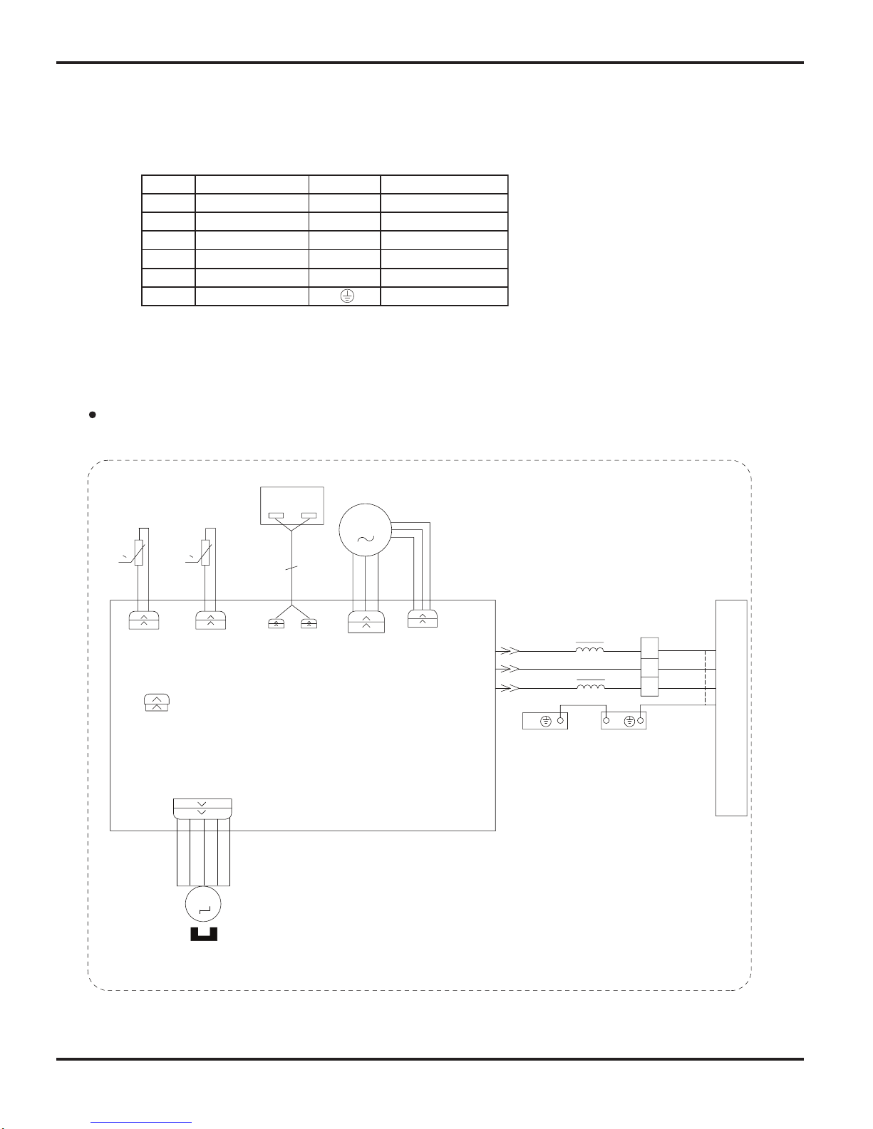
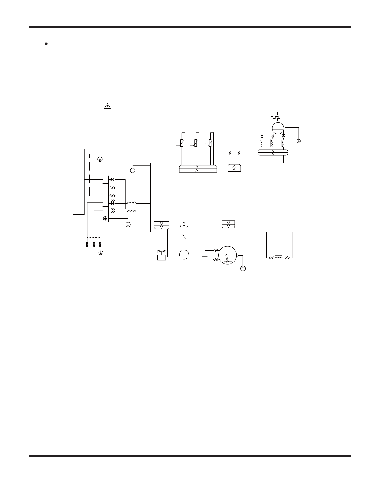
5.2 Electrical Wiring
Indoor unit
5. Schematic Diagram
Symbol Color symbol Symbol Color symbol
Symbol Parts name
BU BLUE
BN BROWN
YE YELLOW
BK BLACK
WHITE
RD RED
YEGN WHYELLOW GREEN
VT VIOLET
PROTECTIVE EARTH
OG ORANGE
RT1
PRINTED CIRCUIT BOARD
EARTHING PANEL
EVAPORATOR
YEGN
BN
BK
BU
OUTDOOR UNIT
M2
ROOM
TUBE
AP1
RT2
BK
BN
3
XT
2
N(1)
BU
YEGN
0
AP2
PEPE
M1
CAP
JUMP
DISP2
PGF
PG
TEM.SENSOR
TUBE ROOM
TEM.SENSOR
MOTOR
SWING
0
AC-L
N
COM-OUT
DISP1
DISPLAY
SWING-UD
Schematic Diagram
14
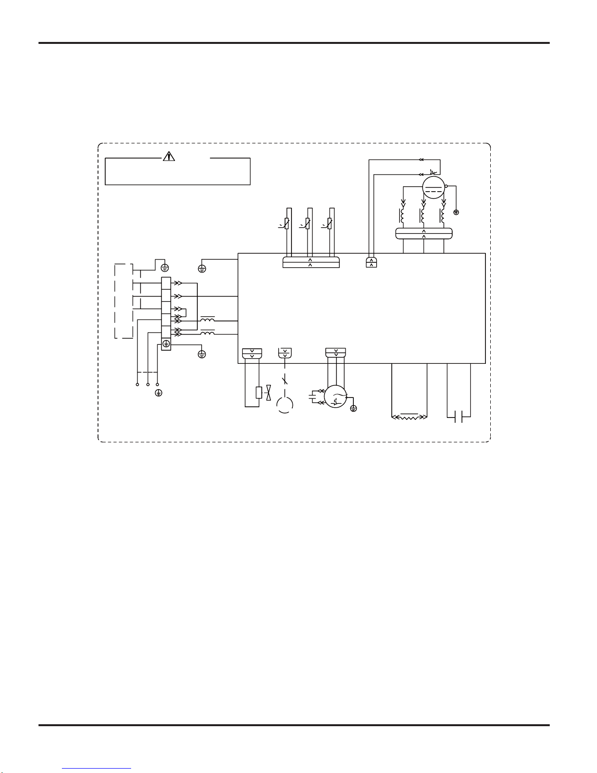
Outdoor unit
INDOOR UNIT
PE
BU
BN
N
L
PE
PE
N(1)
2
3
XT1
BK
BN
BU
YEG N
T- SENSOR
6YEGN
AC-L
N
PE
COMP-W COMP-V COMP-U
YE
BU
RD
U
V
W
PE
PE
COM-INNER
0
RT 1
0
RT 2
RT 3
0
4V
M1
L
INDC1
3RD
WH
PE
OF AN
OVC-COMP
5W H
4W H
SA T
OG
INDC2
COMP
4Y V
X1
CAP .
RD
BN
COMP .
2YE
1BU
WH
BK
TEM.SENSO R
OUTTUBE
OUTROO M
TEM.SENSO R
EXHAUST
TEM.SENSO R
YEG N
PE
FA N MO TO R
TERMINAL
BLOC K
4- WA Y VA LV E
C1
AP1
BU
BK
BN
YEG N
BN
BU
YEG N
EKV
FA
(OPTIONAL)
YEG N
N
L
POWE R
WA RNING
Please don't touch any terminal when the aircondition is
running or during the 15 minutes after the aircondition
stops to prevent the risk of electrical shock!
C1VO-18
Schematic Diagram
15
T-SENSOR
6YEGN
AC-L
N
14YEGN
10BU
PE
9BN
11BK
AP1
XT
3
2
N(1)
COMP-U
16BU
15YE
17RD
U
V
W
E
PE
PE
COM-INNER
0
RT1
0
RT2
RT3
0
4V
L
INDC1
1YE
2BU 3RD
12WH
OVC-COMP
5WH
4WH
SAT
13OG
INDC2
COMP
TEM.SENSOR
EXHAUST
TEM.SENSOR
OUTROOM
TEM.SENSOR
OUTTUBE
INDOOR UNIT
FA
EKV
PE
L
N
8BN
7BU
PE
PFCC2
19YE
18YE
PFCC1
C2
X1
20YEGN
COMP-V COMP-W
BU
BK
BN
YEGN
BN
BU
YEGN
(optional)
YEGN
C
RD
BN
FAN MOTOR
OFAN
PE
4YV
POWER
WARNING
Please don't touch any terminal when the voltage of
terminal P(DC+) and N(DC-) at AP1 is higher than 30V
to prevent the risk of electrical shock!
L
N
M
C1VO-24
Schematic Diagram
16
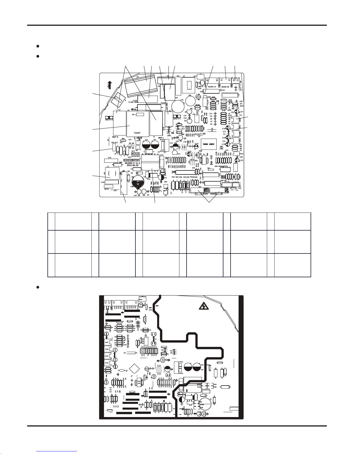
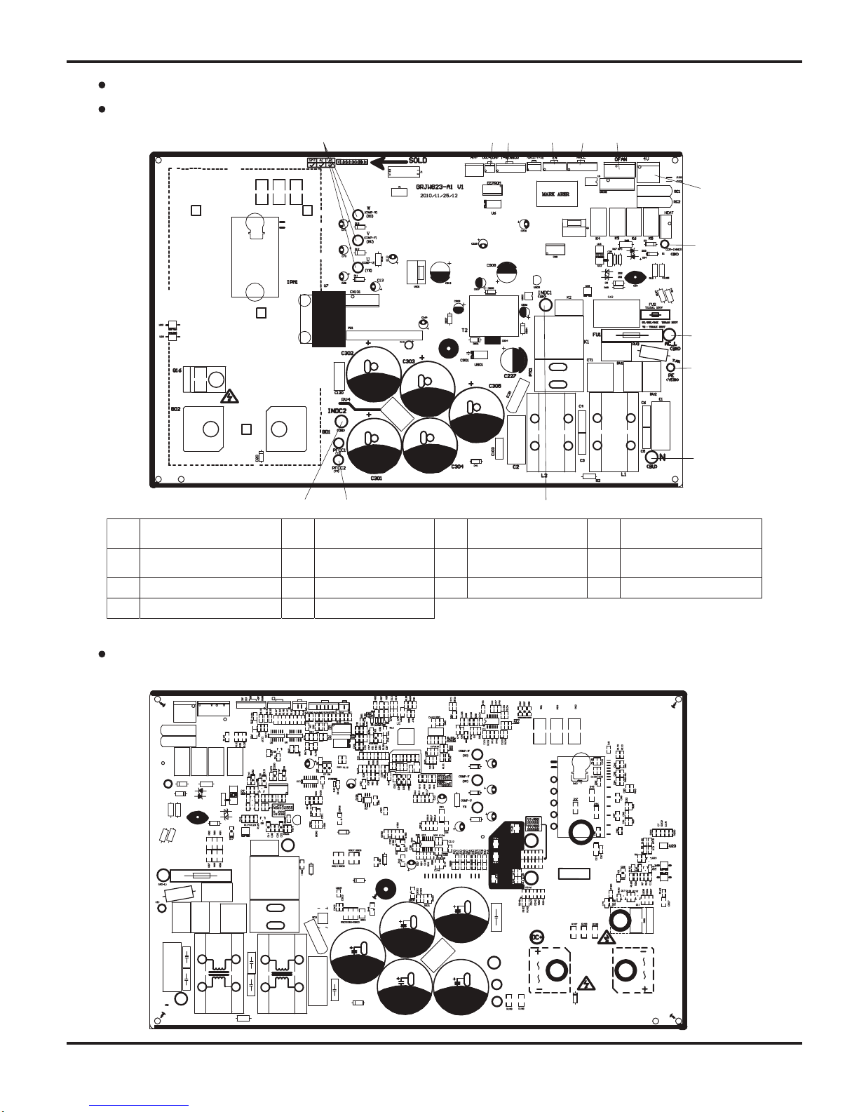
5.3 Printed Circuit Board
TOP VIEW
BOTTOM VIEW
Indoor unit
1
Copper pin
terminal of
neutral wire
2
Auxiliary heating
relay K1, K2
3 Fan capacitor 4 Protective tube 5 Health relay K3 6 PG motor terminal
7 Piezoresistor 8 Jumper cap 9
Up&down swing
terminal
10
PG feedback
terminal
11
Terminal of
ambient
temperature
sensor
12
Terminal of tube
temperature
sensor
13
Connect display
board
DISP1,DISP2
terminals
14
High-frequency
transformer T1
15 Rectifier DB1 16
Strainer
SF2022A-05220
17
Connect copper
terminal of
communication
line for indoor fan
1
8
Supply power for
control relay K4
of outdoor fan
1
2 3 4 5 6 7 8 9
10
11
12
13
1415
16
17
18
Schematic Diagram
17
TOP VIEW
BOTTOM VIEW
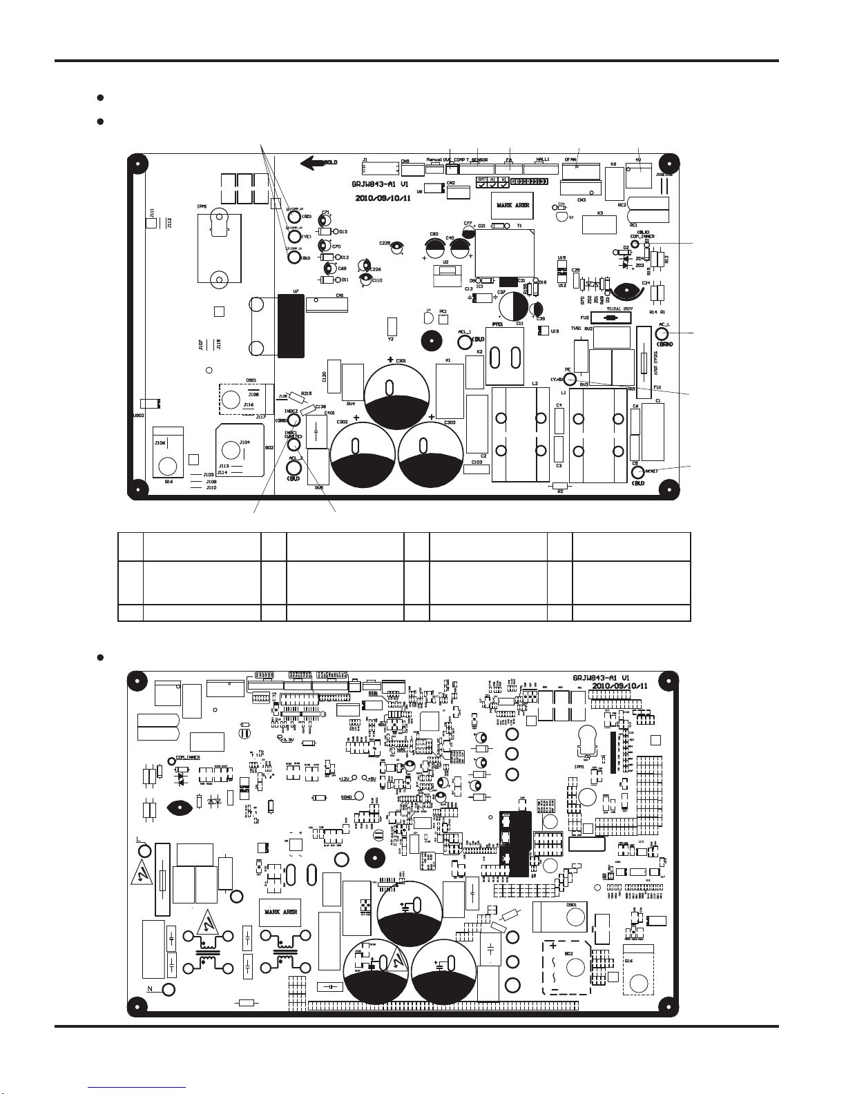
Outdoor unit(18k)
1
2 3 4
5
6
7
8
9
10
11
12
1 Compressor interface 2
Compressor
overloadprotector
3 Temperature sensor 4
Electric expansion
valve
5
Outdoor fan 6 4-way
valve
6 4-way valve 7
Communication
interface with indoor
unit
8 Live wire
9 Neutral wire 10 Earthing wire 11 Reactor interface 12 Reactor interface 2
Schematic Diagram
18
1
2 3 4 5 6
7
8
9
10
11
13 2141
1 Compressor interface 2
Compressor overload
protector
3 Temperature sensor 4 Electric expansion valve
5 Fan HALL interface 6 Outdoor fan 7 4-way valve 8
Communication interface
with indoor unit
9 Live wire 10 Earthing wire 11 Neutral wire 12 Reactor interface 1
13 PFC capacitor interface 1 14 Reactor interface 2
TOP VIEW
BOTTOM VIEW
Outdoor unit(24k)
Function and Control
19
6. Function and Control
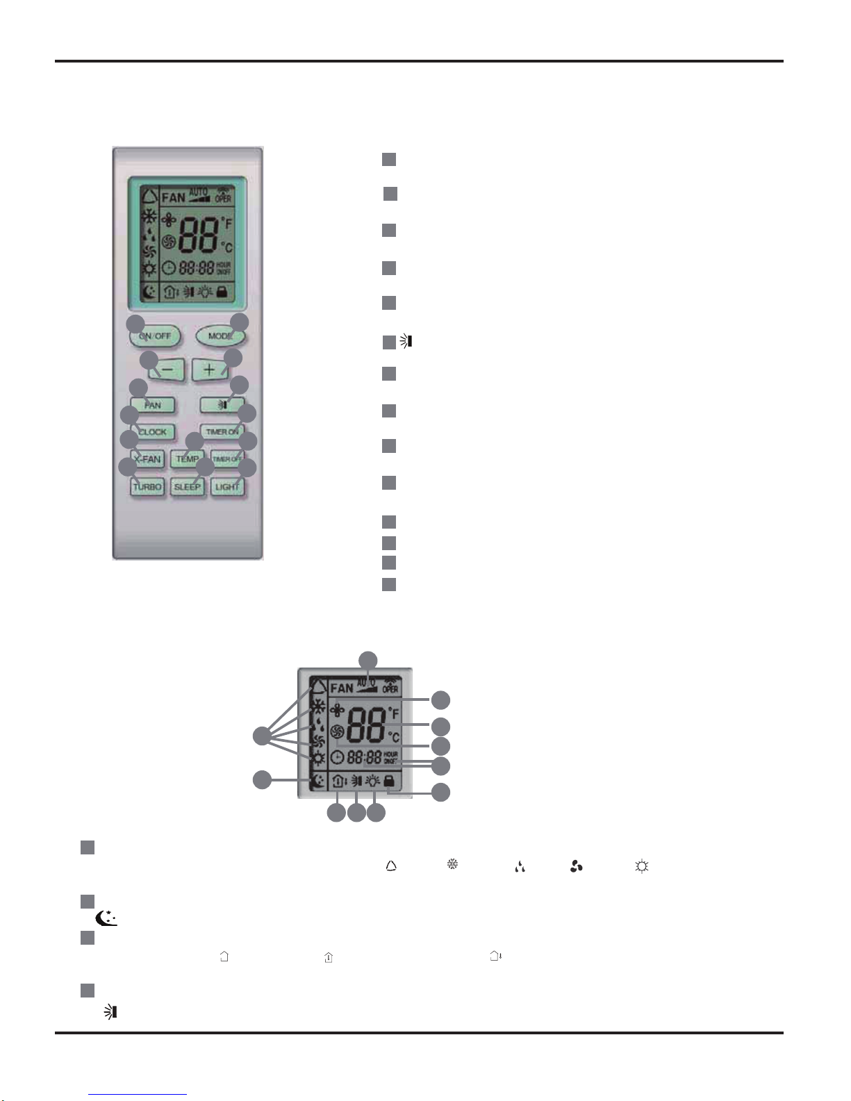
6.1 Remote Control Operations
1
7
8
4
3
5
6
11
13
12
16
17
18
10
14
9
15
2
2
8
9
10
3
4
11
12
7
6
13
14
5
1
ON/OFF
Press it to start or stop operation.
MODE
Press it to select operation mode (AUTO/COOL/DRY/FAN/HEAT).
+
Press it to increase temperature setting.
-
Press it to decrease temperature setting.
FAN
Press it to set fan speed.
Press it to set swing angle.
TIMER ON
Press it to set auto-on timer.
TIMER OFF
Press it to set auto-off timer.
CLOCK
Press it to set clock.
(X-FAN is the alternative expression of BLOW for the
purpose of understanding.)
X-FAN
TEMP
TURBO
SLEEP
LIGHT
Press it to turn on/off the light.
171518 19
16
20
21
23
24
22
25
MODE icon:
If MODE button is pressed, current operation mode icon (AUTO), ( COOL), (DRY), (FAN) or (HEAT is only for heat
pump models) will show.
SLEEP icon :
is displayed by pressing the SLEEP button. Press this button again to clear the display.
TEMP icon:
Pressing TEMP button, (set temperature), (indoor ambient temperature), (outdoor ambient temperature) and blank is
displayed circularly.
Up & down swing icon:
is displayed when pressing the up & down swing button. Press this button again to clear the display.
Function and Control
20
20
21
22
23
24
25
1
2
3
4
5
6
19
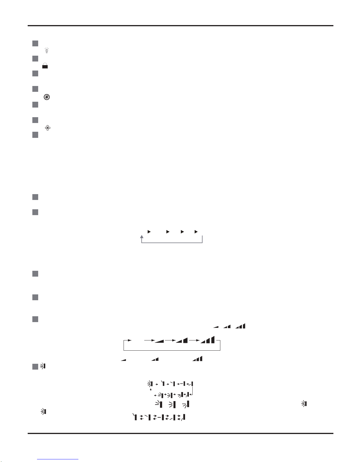
LIGHT icon:
is displayed by pressing the LIGHT button.Press LIGHT button again to clear the display.
LOCK icon:
is displayed by pressing "+" and “-” buttons simultaneously.Press them again to clear the display.
SET TIME display:
After pressing TIMER button, ON or OFF will blink.This area will show the set time.
TURBO icon:
is displayed when pressing theTURBO button.Press this button again to clear the display.
DIGITAL display:
This area will show the set temperature. In SAVE mode,"SE" will be displayed. During defrosting operation, “H1” will be displayed.
X-FAN icon:
is displayed when pressing the X-FAN button. Press this button again to clear the display.
FAN SPEED display:
Press FAN button to select the desired fan speed setting(AUTO Low-Med-High).Your selection will be displayed in the LCD windows,
except the AUTO fan speed.
ON/OFF:
Press this button to turn on the unit. Press this button again to turn off the unit.
MODE:
Each time you press this button,a mode is selected in a sequence that goes from AUTO, COOL,DRY, FAN, and HEAT *, as the
following:
*Note: Only for models with heating function.
After energization, AUTO mode is defaulted. In AUTO mode, the set temperature will not be displayed on the LCD, and the unit will
automatically select the suitable operation mode in accordance with the room temperature to make indoor room comfortable.
+ :
Press this button to increase set temperature. Hold it down for above 2 seconds to rapidly increase set temperature. In AUTO mode,
set temperature is not adjustable.
-:
Press this button to decrease set temperature. Hold it down for above . 2 seconds to rapidly decrease set temperature. In AUTO
mode, set temperature is not adjustable.
FAN :
This button is used for setting fan speed in the sequence that goes from AUTO, , , to then back to Auto.
Press this button to set up & down swing angle, which circularly changes as below:
This remote controller is universal. If any command , or is sent out, the unit will carry out the command as
indicates the guide louver swings as:
AUTO
COOL DRY FAN HEAT*AUTO
Low speed Medium speed High speed
OFF
Remote Controller Description
Function and Control
21
8
9
10
11
12
13
14
15
16
7
TIMER ON:
Press this button to initiate the auto-ON timer. To cancel the auto-timer program, simply press this button again. After pressing this
button, disappears and "ON" blinks . 0 0:00 is displayed for ON time setting. Within 5 seconds, press + or - button to adjust the
time value. Every press of either button changes the time setting by 1 minute. Holding down either button rapidly changes the time
setting by 1 minute and then 10 minutes. Within 5 seconds after setting, press TIMER ON button to confirm.
TIMER OFF:
Press this button to initiate the auto-off timer. To cancel the auto-timer program, simply press the button again.TIMER OFF setting is
the same as TIMER ON.
CLOCK :
Pressing CLOCK button, blinks. Within 5 seconds, pressing + or - button adjusts the present time. Holding down either button
above 2 seconds increases or decreases the time by 1 minute every 0.5 second and then by 10 minutes every 0.5 second. During
blinking after setting, press CLOCK button again to confirm the setting, and then will be constantly displayed.
X-FAN:
Pressing X -FAN button in COOL or DRY mode,the icon is displayed and the indoor fan will continue operation for 10 minutes in
order to dry the indoor unit even though you have turned off the unit.
After energization, X-FAN OFF is defaulted. X-FAN is not available in AUTO, FAN or HEAT mode.
TEMP:
Press this button, could select displaying the indoor setting temperature or indoor ambient temperature.When the indoor unit firstly
power on it will display the setting temperature, if the temperature's displaying status is changed from other status to" ",displays
the ambient temperature, 5s later or within 5s, it receives other remote control signal that will return to display the setting temperature. if the users haven't set up the temperature displaying status,that will display the setting temperature.
TURBO:
Press this button to activate / deactivate the Turbo function which enables the unit to reach the preset temperature in the shortest
time. In COOL mode, the unit will blow strong cooling air at super high fan speed. In HEAT mode, the unit will blow strong heating air
at super high fan speed.
SLEEP:
Press this button to go into the SLEEP operation mode. Press it again to cancel this function. This function is available in COOL,
HEAT (Only for models with heating function) or DRY mode to maintain the most comfortable temperature for you.
LIGHT:
Press LIGHT button to turn on the display's light and press this button again to turn off the display's light. If the light is turned on ,
is displayed. If the light is tunrned off, disappears.
Combination of "+" and "-" buttons: About lock
Press "+ " and "-" buttons simultaneously to lock or unlock the keypad. If the remote controller is locked, is displayed. In this
case, pressing any button, blinks three times.
Combination of "MODE" and "-" buttons:About switch between Fahrenheit and Centigrade At unit OFF, press "MODE" and "- "
buttons simultaneously to switch between
and .
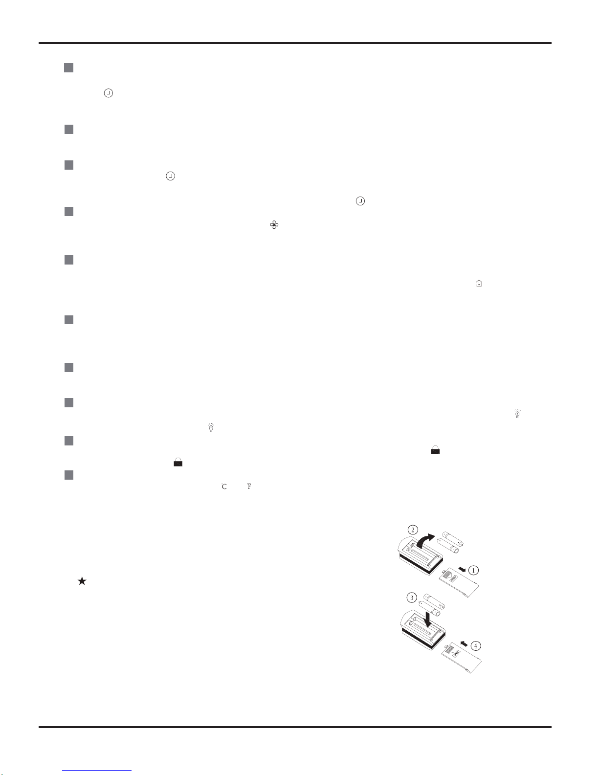
Replacement of Batteries
1.Remove the battery cover plate from the rear of the remote controller.
(As shown in the figure)
2.Take out the old batteries.
3.Insert two new AAA1.5V dry batteries, and pay attention to the polarity.
4. Reinstall the battery cover plate.
Notes:
●When replacing the batteries, do not use old or different types of batteries.
Otherwise, it may cause malfunction.
●If the remote controller will not be used for a long time,
please remove batteries to prevent batteries from leaking.
●The operation should be performed in its receiving range.
●It should be kept 1m away from the TV set or stereo sound sets.
●If the remote controller does not operate normally, please take the
batteries out and reinsert them after 30 seconds. If it still can't operate
properly, replace the batteries.
Sketch map for
replacing batteries
Function and Control
22
6.2 Description of Each Control Operation
1.Basic function of system
(1)
Cooling mode
1.Under this mode, fan motor, swing will work under setting status, the temp. range is 16-30
(61-86 Fahrenheit
scale)
2.Outdoor unit malfunction or unit stop running, indoor unit will keep original running status, malfunction displayed.
3.When 0 (Tset-Tamb.), if indoor fan motor is high speed, that the fan motorist running in middle speed, the
middle speed or low speed will be maintained;(this condition should be executed when compressor start up);the super
high speed will not rotate; When (Tamb-Tset) , the fan will return to the setting fan speed.
(2)Dehumidifying mode
1.Under this mode, fan motor will run at low speed, swing will work at setting status, setting temp. range is 16-30
(61-86 Fahrenheit scale)
2.Outdoor unit malfunction or protection, unit will stop, indoor unit will keep original running status, malfunction
displayed.
(3)Fan mode
Under this mode, indoor fan motor could be setted at high speed, middle speed, low or auto speed, compressor,
outdoor unit and four-way valve will stop to run.
Under this mode, temp. range should be 16-30 (61-86 Fahrenheit scale)
(4)Heating mode
1.Under this mode, temp. range should be 16-30 (61-86 Fahrenheit scale)
2.Working condition
and procedure of heating mode: When unit turn on and enter into Heating mode, indoor unit
enter into anti-cool wind mode, when unit is stop running, and indoor fan motor turns on, blowing heat will act.
3.Protection function, under heating mode, compressor will stop to run due to malfunction happened, indoor fan
motor will blow surplus heat.
4.Defrosting control: When receiving the defrosting signal from outdoor unit, displayer will display H1, 10s later,
indoor fan motor will stop to run.
5.Anti-coold wind function
6.Blow heat air function
a.If heating temp. meets the compressor stop running condition, compressors, outdoor fan motor will stop to run,
the upper and lower guide louver will rotate to horizontal position L, indoor fan motor run at setting fan speed
for 60s, then the indoor fan motor will stop to run.
b.Dueto PG motor block running, the air guide board will keep the position when it
stopping. (under each mode),
other malfunction unit will stop to run, the upper and lower air guide louver will rotate to horizontal position
L, indoor fan unit will run at setting fan speed and run for 60s, indoor fan unit will stop to run.
(5)Auto mode:
1.When Tam
26 , select the cooling mode, at this time, the setting temp. is 25 .(77 Fahrenheit scale)
2.Cooling and heating units: Tamb 22
,will runat heating mode, at this time, the setting temp. is 20
3. Cooling only unit: When Tamb 22 , it will run at Fan mode, the setting temp. is 25 (77 Fahrenheit scale)
4.When 23 Tindoor amb. 25 ,firstly enter into auto mode and run at auto fan speed, other modes will
run at auto mode, will keep the previous running mode. (When entering into Dehumidifying mode, it will run at
auto fan speed)
(6)Auto fan speed control mode
(68Fahrenheit scale)
6.2.1 Functions of Indoor Unit
Function and Control
23
2. Display state of indoor indicators
(1) State of indoor display board
1. When the unit is powered on, all patterns will be displayed and then only power indicator is on. When the unit is turned on
with a remote controller, the operating indicator is on and operation mode which is set currently is displayed.
2. In defrosting mode, "H1" is displayed on "Double 8".
3. Set temperature is displayed on "Double 8".
Display of operation patterns and mode patterns
When the unit is powered on, all patterns will be displayed and the standby operation indicator will become red. When the unit
is turned on through a remote controller, the operation indicator is light. At the same time, operating mode patterns (mode
indicators include cooling, heating and dehumidification modes) set currently are displayed, and dynamic display patterns of
wind speed are displayed. If the light button is switched off, all display will be turned off.
Temperature display control mode of separated air conditioner
1. When user sets the remote controller at set temperature display, currently set temperature will be displayed.
2. Only when remote signals are converted from other display states into indoor ambient temperature display state, the
remote controller will display indoor ambient temperature for 5 seconds and then return to set temperature display.
3. Only when remote signals are converted from other display states into outdoor ambient temperature display state, the
remote controller
will display outdoor ambient temperature for 5 seconds and then return to set temperature display.
4. If the controller is lack of outdoor display functions, as the signal is received, set temperature will be displayed.
5. When the unit is turned off, temperature display will be compulsively set at given temperature by the controller. When the
unit is turned on, patterns as set by remote signals will be displayed.
6. If user does not set up temperature display state, given temperature will be displayed.
(2) Failure display of indoor unit
1. Requirements for failure display
When multiple failures appear at the same time, failure protection codes shall be displayed alternatively.
(1) Hardware failures shall be displayed immediately, referring to requirements in "Failure State Display Table";
(2) Operation states shall be displayed immediately, referring to requirements in "Failure State Display Table";
(3) Other failures shall be displayed 200s after the compressor stops, referring to requirements in "Failure State Display Table".
(Note: in
the case that the unit is switched off with the remote controller, or the compressor is switched on again, failure
display waiting time (200s) shall be cleared.)
(4) Frequency limitation and reduction states shall be displayed by means of remote calling.
3. Failure display control
Indicator failure display shall be kept synchronous with Double 8 failure display, that is, during indicator blinking, failure code
corresponding to such indicator shall be displayed on Double 8.
4. Method of remote calling of failure display
Entering the failure remote calling mode: push the light button four times within 3s to call out relevant failure protection code;
Quit the failure remote calling mode: push the light button four times within 3s or call out failure display to enter it for 5 minutes
and then quit.
3. Other control targets
(1) Up and down wind blow functions: model of stepping motor is MP28EA.
When the unit is powered on, the up and down wind blow motor will turn a wind deflector anti-clockwise to Position 0 to shut
down the air outlet. When the unit is switched on and wind blow function is not preset, under the heating mode, up and down
wind blades will turn clockwise to position D; and under other modes, the up and down wind blades will turn clockwise to
position L. If wind blow function is set at the same time as the unit is switched on, the wind blades will swing between position
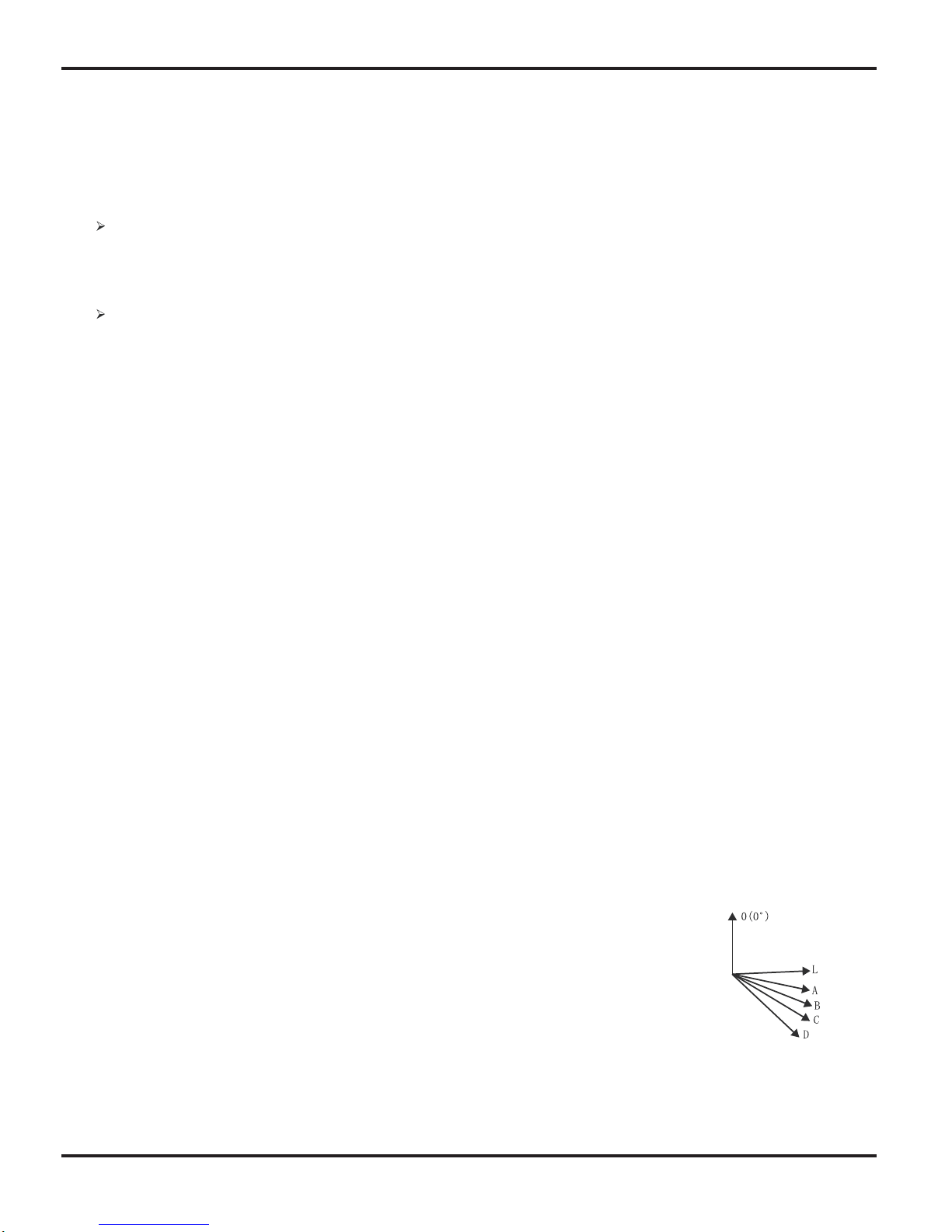
L and D. The wind blades can be kept in seven states: position L, position A, position B, position C, position D, swing between
position L and D, stop at one position from L to D. When the unit is turned off, the wind deflector will be closed up to position 0.
Wind blow action is effective only when wind blow commands are set and the indoor unit is running.
Note: When the wind blades are set at position L to B, position A to C, or position B to D through
remote setting,
the wind deflector will swing between position L and D. L—A—B—C—D.
(2) Buzzer
When the controller is powered on, signals from a remote controller are received, or the auto button
is pushed, a buzzer will give out prompt tone.
(3) Auto button
When the button is pushed, the unit will operate in auto mode and the indoor fan will run in auto state. When the indoor fan is
running, the wind blow motor will work. When the button is pushed again, the unit will be switched off. At the same time as the
button is pushed, the whole unit will be powered on and enter into fast test mode; when the unit is powered on and detects for
continuous 20s (such time shall not be fast tested) that the auto button is pushed, and if the unit is currently at fast test state,
the unit will quit the fast test state.
Function and Control
24
(4) Sleep function
This mode is effective only in cooling and heating modes. Proper sleep curves shall be selected for operation according to
preset temperature.
In cooling mode:
(1) When initial temperature is set at 16-23 , an increase of 1 will be gained every hour after the sleep function is activated.
After 3 is raised, the temperature will be maintained. After operation for 7 hours, temperature will go down by 1 ,
afterwards, the unit will operate at such temperature.
(2) When initial temperature is set at 24-27 , an increase of 1 will be gained every hour after the sleep function is activated.
A
fter 2 is raised, the temperature will be maintained. After operation for 7 hours, temperature will go down by 1 ,
afterwards, the unit will operate at such temperature.
(3) When initial temperature is set at 28-29 , an increase of 1 will be gained every hour after the sleep function is activated.
fter 1 is raised, the temperature will be maintained. After operation for 7 hours, temperature will go down by 1 ,
afterwards, the unit will operate at such temperature.
In heating mode:
(1) When initial temperature is set at 16 , the unit will operate at such temperature.
(2) When initial temperature is set at 17-20 , a decrease of 1 will be gained every hour after the sleep function is
activated. After 1 is reduced, the temperature will be maintained.
(3) When initial temperature is set at 21-27 , a decrease of 1 will be gained every hour after the sleep function is
activated. After 2 is reduced, the temperature will be maintained.
(4)
When initial temperature is set at 28-30 , a decrease of 1 will be gained every hour after the sleep function is
activated. After 3 is reduced, the temperature will be maintained.
(5) Timing function
The main board integrates general timing and moment timing. Such two timing functions can be selected through a remote
controller on which different functions are arranged.
1
General timing:
Timing start: timing start can be set when the unit is off. When preset time is reached, the controller will operate in a preset
mode. Timing can be set at an interval of 0.5 hour in a scope of 0.5 - 24 hours.
Timing stop: timing stop can be set when the unit is on. When preset time is reached, the system will be turned off. Timing
can be set at an interval of 0.5 hour in a scope of 0.5 - 24 hours.
2
Moment timing
Timing start: if timing start is set when the system is at operation state, the system will continue to operate; if timing start is set
when the system is at stop, as the preset time is reached, the system will start to run in preset mode.
Timing stop: if timing stop is set when the system is at stop state, the system will keep standby; if timing stop is set when the
system is in operation, as the preset time is reached, the system will stop running.
Timing change:
When the system is in timing mode, start and stop can be set through the On/Off button on the remote controller; or timing
time can be reset and the system will operate according to the latest setting.
When the system is in operation and both timing start and stop are set, the system will stay at currently set operation state.
When preset timing stop time is reached, the system will stop working.
When the
system is at stop state and both timing start and stop are set, the system will keep at stop state. When preset timing
start time is reached, the system will start operation.
From then on, the system will operate in preset mode at a preset start time and stop at a preset stop time everyday. If timing
stop time is set as the same as timing start time, a stop command will be executed.
(6) Dry and mildew proof function
Dry and mildew proof function can be set in cooling and dehumidification modes.
(7) Control of indoor fan
Indoor fan can be set at four levels, super-high, high, middle and low, with a remote controller. When one level is set, the fan
will thus operate at such level. The fan can also be set at auto state.
(8) Power off Memory Function
What will be memorized includes modes, up and down wind blow, light, preset temperature, preset wind speed, general timing
(no memory for moment timing), and Fahrenheit /Celsius degree. When the unit is powered on again after power failure,
operation continues according to memorized content. If timing is not set by the last remote control command, the system will
memorize the last remote control command and operate in the mode specified in the last remote control command. If timing is
set by the last remote control command and power failure happens before the preset time, the system, as powered on again,
will memorize the timing function set by the last remote control command. Timing will be re-counted from the time at which the
system is powered again. If timing is set by the last remote control command and timing of start or stop is reached before
power failure, the system, as powered on again, will memorize operation state before power failure and will not perform timing
action. Moment timing is out the range of memor
y.

Function and Control
25
(9) Locked Protection of PG Motor
When starting up the fans, if the motor has run at a lower speed continuously for a period, for preventing
automatic protection of the motor, stop running, and display the locked operation; if the machine is running at
present, the code of the locked fault---H6 of double-eight digital tubes will be displayed; if the machine is shut
down at present, the information of the locked fault will not be displayed.
(10) Super Power Function
In cooling and heating modes (automatic, dehumidifying and air-supplying modes are without strong power),
press the button of Super Power, the wind speed on the remote controller is displayed as super-high air flow, and
the inner fans are also turned to super-high air flow;
(11) Health Function
When the inner fans are running, the remote controller is set at the Health function at this time (if there is no
Health button on the remote controller, the Health On order is defaulted), then start the Health function device.
5. Fault Detection of Temperature Sensor
(1) Indoor Environment Temperature Sensor:
Detect the fault of thermo-bulb at any time;
(2) Indoor Pipe Temperature Temperature Sensor:
During the defrosting period, the fault of the thermo-bulb will be not detected, which shall be detected in 5
minutes after defrosting is completed; the fault of the thermo-bulb will be detected at other times;
(3) Protecting Treatments of Temperature Sensor:
1.When
the thermo-bulb is detected to be short-circuited continuously for 30 seconds:
It is
regarded that the temperature detected by the thermo-bulb is over-high (or unlimited), then the whole
machine will exert corresponding safety stops according to the over-high temperature sensed by the thermo-bulb,
and display corresponding temperature safety stops and faults of the thermo-bulb simultaneously.
2. When the thermo-bulb is detected in open circuit continuously for 30 seconds: stop the machine in protection,
directly display corresponding faults of the thermo-bulb.
6. Forced Running Function of the Inner Units
(1) Enter into Forced Running Control
Within 5 minutes after power-up, press the Lights Off button on the remote controller continuously for three
times within 3 seconds to enter into the fluorine collecting mode, and display Fo, send the fluorine-collecting
mode for 25 minutes continuously, each load will be treated as cooling when starting the machine (set the air flow
as High, set the temperature as 16
).
(2) Exit from the Forced Running Control
After receiving any remote signal, or signal of keys, the fluorine-collecting mode will exit, and operate in
accordance with the current orders set; or exit the fluorine-collecting mode after running for 25 minutes, and the
machine will be shut down automatically.
(It is refrigerants reclaiming function which is used for the condition that refrigerants cannot be reclaimed by
cooling operation in the season with low temperature.)
Function and Control
26
1. Input Parameter Compensation
(1) Input parameter compensation function
A
s the structure feature of split unit, concerning the comfort, in heating mode, when compressor stops, the indoor ambient
temperature is higher than preset temperature for 3 .
2. Check parameters to effectively make judgment and control
Insert the outdoor discharge temp sensor into corresponding temp sensor jacket of discharge pipe in order to protect safe and
reliable operation of the unit, so that the control system can accurately detect the discharge temp as well as effectively control
and protect it. Otherwise, the unit will stop and display the trouble of “outdoor discharge temp sensor failure ( not be inserted
correctly)” which can be recovered by pressing ON/OFF button.
3. Cooling Mode
3.1 Conditions and processes of cooling operation:
3.1.1 If the compressor stops, and [Tpreset – (Tindoor ambient – ΔTcooling indoor ambient temperature compensation)] ≤0.5 ,
start up the unit for cooling operation;
3.1.2 During cooling operation, if 0
≤ [Tpreset – (Tindoor ambient –ΔTcooling indoor ambient temperature compensation)]< 2 ,
keep the cooling operation;
3.1.3 During cooling operation, if 2
≤ [Tpreset – (Tindoor ambient –ΔTcooling indoor ambient temperature compensation)], the
cooling operation will stop after reaching to the setting temperature.
3.2 Temperature setting range
3.2.1 If Toutdoor ambient ≥ [Tlow-temperature cooling], the temperature can be set at: 16~30
(Cooling at roomemperature);
3.2.2 If Toutdoor ambient < [Tlow-temperature cooling], the temperature can be set at: 25~30
(Cooling at low temperature),
that is, the minimum setting temperature to be judged by outdoor unit is 25
.
4. Dry Mode
4.1 Conditions and processes of dry operation: same as the cooling mode;
4.2 The temperature setting range is: 16~30
;
5. Fan Mode
5.1 The compressor, outdoor fan and four-way valve are switched off;
5.2 The temperature setting range is: 16~30
.
6. Heating Mode
6.1. Conditions and processes of heating operation: (Tindoor ambient is the actual detection temperature of indoor
environment temp sensor, ΔTheating indoor ambient temperature compensation is the indoor ambient temperature compensation
during heating operation)
6.1.1 If the compressor stops, and [(Tindoor ambient –ΔTheating indoor ambient temperature compensation) –Tpreset]≤ 0.5
,
start the unit to enter into heating operation;
6.1.2 During heating operation, if 0
≤ [(Tindoor ambient –ΔTheating indoor ambient temperature compensation)–Tpreset] < 2 ,
keep the heating operation;
6.1.3 During heating operation, if 2
≤ [(Tindoor ambient –ΔTheating indoor ambient temperature compensation)–Tpreset], the
heating operation will stop after reaching the setting temperature.
6.2 The temperature setting range in this mode is: 16~30
.
7. Defrosting Control (heating)
7.1 After the time for defrosting is judged to be satisfied, if the temperature for defrosting is satisfied for continuous 3minutes, the
defrosting operation will start.
7.2 Start defrosting: Compressor stops and starts up 55S later;
7.3 Finish of Defrosting: Compressor stops and starts up 55S later;
7.4 The defrosting operation can exit when any of the conditions below is satisfied:
7.4.1 Toutdoor pipe≥ 12
;
7.4.2 Toutdoor ambient
-5 , and the Toutdoor pipe≥ 6 last more than 80S;
7.4.3The continuous running time of defrosting reaches.
8. Compressor Control
8.1. The frequency of compressor will be controlled according to the relationship of ambient temperature and preset temperature
as well as changing speed of ambient temperature;
8.2 Start the compressor after starting cooling, heating, dry operation, and the outdoor fan for 5s;
8.3 When the unit is off, in safety stops and switching to fan mode, the compressor will stop immediately;
8.4 In all modes: once the compressor starts up, it will not be allowed to stop within 7 min. (Note: except the cases that require
stop of the compressor such as fault protection, remote shutdown, mode switching etc.);
6.2.2 Functions of Outdoor Unit

Function and Control
27
8.5 In all modes: once the compressor stops, it can’t restart within 3-minute (Note: The indoor units with memory function can be
restarted after remote shutdown and powering on again without delay).
9. Outdoor Fan Control
9.1 When the unit is off by remote control in safety stops or stops after reaching the setting temperature, 1min later,the outdoor
fan will stop;
9.2 In fan mode: The outdoor fan stops;
9.3 Start of defrosting: Outdoor fan will stop after compressor stops for 50S;
9.4 Finish of defrosting: Outdoor fan will start up when the compressor stops.
10. 4-way valve control
10.1 The 4-way valve is off under the modes of Cooling, dry and fan;
10.2 In heating mode, the 4-way valve is energized;
10.3 When the unit is off in heating mode or heating mode shifts to other modes, the 4-way valve will be de-energized after
compressor stops for 2min;
10.4. After protection stops, the 4-way valve will be de-energized after 4min;
10.5 Start of defrosting: when entering defrosting mode, 4-way valve will be de-energized after the compressor stops for 50s;
10.6 Finish of defrosting: The 4-way valve will be energized after the compressor stops for 50s.
11. Anti-freezing protection
11.1 In cooling and dry mode, if Tindoor pipe 0 is detected for 3min continuously, the unit will stop; if 6 Tindoor pipe, and
compressor has stopped for 3min, the unit will resume running;
11.2 In cooling and dry mode, if Tindoor pipe
6 , running frequency of compressor will be decreased or stop increasing;
11.3 If the unit stops as anti-freezing protection for 6 times, it can not resume running automatically and display trouble code, it
can resume by pressing ON/OFF button. During operation, if the compressor operates for over 10min, the times of anti-freezing
protection stop will be cleared to zero. When the unit is off/ fan/ heating mode, the malfunction and malfunction times will be
cleared to zero. (If the malfunction can not be removed)
12. Overload protection
12.1 In cooling and dry mode: if 65 ≤Toutdoor pipe, the unit will stop; if Toutdoor pipe 55 , and compressor has stopped for
3min, the unit will resume running;
12.2 In cooling and dry mode: if 55
≤Toutdoor pipe, running frequency of compressor will be decreased or stop increasing;
12.3 In heating mode: if 64
≤Tindoor pipe, the unit will stop; if Tindoor pipe 54 , and compressor has stopped for 3min, the
unit will resume running;
12.4 In heating mode: if 54
≤Tindoor pipe, running frequency of compressor will be decreased or stop increasing;
12.5 If the unit stops as overload protection for 6 times, it can not resume running automatically and display malfunction. It can
resume running by pressing ON/OFF.During operation, if the compressor has operated for over 10 min, the times of overload
protection stop will be cleared to zero. When the unit is off or in Fan mode or shifts to heating mode, the malfunction and
malfunction times will be cleared to zero immediately. (If the malfunction can not be removed)
13. Compressor discharge temperature protection
13.1 If 115 ≤Tdischarge, the unit will stop; if Tdischarge 97 , and compressor has stopped for 3min, the unit will resume
running;
13.2 If 97
≤Tdischarge, running frequency of compressor will be decreased or stop increasing;
13.3 If the unit stops as protection of compressor discharge temperature for 6 times, it can not resume running
automatically and malfunction will be displayed. It can resume running by pressing ON/OFF. During operation, if the compressor
has operated for over 10min, the time of compressor discharge temperature stop will be cleared to zero.When the unit is off/
shifts to fan mode, the malfunction and malfunction times will be cleared. (If the malfunction can not be removed)
14. Current protection
14.1. If 12A≤I alternating-current, running frequency of compressor will be decreased or stop increasing;
14.2. If 17A≤I alternating-current, the unit will stop; and after compressor has stopped for 3min, the unit will resume running;
14.3 If the unit stops as protection for compressor discharge temperature for 6 times, it can not resume running automatically
and malfunction will be displayed. It can resume by pressing ON/OFF button. During operation, if the compressor has operated
for over 10 min, the time of compressor discharge temperature stop will be cleared to zero.
15. Drop off voltage
During compressor operation, the system will stop and malfunction of drop off voltage will occur if voltage downward fluctuates
rapidly, and it will re-start up automatically 3min later.

Function and Control
28
16. Communication malfunction
If the unit does not receive correct signal from indoor unit for 3min continuously, the unit will stop as communication malfunction
protection; if communication malfunction has removed and compressor has stopped for 3min, the unit will resume running.
17. IPM module protection
When the compressor starts, if there is overcurrent or low control voltage for IPM module due to some abnormal results, IPM will
detect module protection signal as the unit is on. Once the module protective signal is detected, stop the unit with module
protection immediately. If the module protection is removed and compressor has stopped for 3min, the unit will be allowed to
operate.If the module protection continuously occurs for three times, it can not be removed automatically, and you should press
the ON/OFF button to resume operation. If the running time of compressor exceeds 10 min, the module protection times will be
cleared.
18. Module overheating protection
18.1 If 80 ≤Tmodule, running frequency of compressor will be decreased or stop increasing;
18.2.If 95
≤Tmodule, the unit will stop; if Tmodule 87 , and compressor has stopped for 3min, the unit will resume running;
18.3 If the unit stops as module overheating protection occurs for 6 times, it can not resume running automatically and
malfunction will be displayed, it can resume by pressing ON/OFF. During operation, if the time exceeds compressor running time,
the time of module overheating protection stop will be cleared. When the unit is off or shifts to fan mode,the malfunction and
malfunction times will be cleared. (If the malfunction can not be removed).
19 Compressor overload protection
19.1 If detect that the overload switch breaks within continuous 3S, the system will stop as protection;
19.2 If detect that the protection has removed and the compressor has stopped for 3min, the unit will be allowed to operate.
19.3 If the unit stops as compressor overload protection occurred for 3 times continuously, it can not resume running
automatically and malfunction will be displayed.
It can resume operation by pressing ON/OFF button; and the times of compressor overload protection will be cleared after the
compressor has run for 30min.

Installation Manual
29
7. Installation Manual
7.1 Notices for Installation
Caution
1.The unit should be installed only by authorized service center according to local or government regulations and in compliance with
this manual.
2.Before installing, please contact with local authorized maintenance center. If the unit isnot installed by the authorized service center,
the malfunction may not be solved due to incovenient contact between the user and the service personnel.
3.When removing the unit to the other place, please firstly contact with the local authorized service center.
4.Warning: Before obtaining access to terminals, all supply circuits must be disconnected.
5.For appliances with type Y attachment, the instructions shall contain the substance of the following. If the supply cord is damaged,
it must be replaced by the manufacturer, its service agent or similarly qualified persons in order to avoid a hazard.
6.The appliance must be positioned so that the plug is accessible.
7.The temperature of refrigerant line will be high; please keep the interconnection cable away from the copper tube.
8.The instructions shall state the substance of the following:
This appliance is not intended for use by persons(including children)with reduced physical, sensory or mental capabilities, or lack
of experience and knowledge, unless they have been given supervision or instruction concerning use of the
appliance by a person
responsible for their safety.
Children should be supervised to ensure that they do not play with the appliance.
7.1.1 Installation Site Instructions
Proper installation site is vital for correct and efficient operation of the unit. Avoid the following sites where:
strong heat sources, vapours, flammable gas or volatile liquids are emitted.
high-frequency electro-magnetic waves are generated by radio equipment,welders and medical equipment.
salt-laden air prevails (such as close to coastal areas).
the air is contaminated with industrial vapours and oils.
the air contains sulphures gas such as in hot spring zones.
corrosion or poor air quality exists.
7.1.2 Installation Site of Indoor Unit
1.The air inlet and outlet should be away from the obstructions. Ensure the air can be blown through the whole room.
2.Select a site where the condensate can be easily drained out, and where it is easily connected to outdoor unit.
3.Select a place where it is out of reach of children.
4.Select a place where the wall is strong enough to withstand the full weight and vibration of the unit.
5.Be sure to leave enough space to allow access for routine maintenance. The installation site should be 250cm or more above the
floor.
6.Select a place about 1m or more away from TV set or any other electric appliance.
7.Select a place where the filter can be easily taken out.
8.Make sure that the indoor unit is installed in accordance with installation dimension instructions.
9.Do not use the unit in the laundry or by swimming pool etc.

Installation Manual
30
7.1.3
Installation Site of Outdoor Unit
1.Select a site where n oise and outflow air emitted by the unit w ill not annoy neighbors.
2.Select a site where t here is sufficient ventilation .
3.Select a site where there is no obstruction blocking the inlet and outlet .
4 .The site s hould be able to withstand t he f ull weight and v ibration.
5.Select a dry place, but do not expose the unit to direct sunlight or strong wind.
6.Make sure that the outdoor unit is i nstalled in a ccordance with the installation instructions, a nd is convenient for m aintena nc e
and r epair .
7.The height difference between indoor and outdoor units is within 10 m, and the length of the connecting tubing does not exceed
30 m.
8.Select a place where it is out of reach of children.
9.Select a place where t he unit does not have
negative impact on p edestrians or on t he city .
7.1.4 Safety Precautions for Electric Appliances
1.A dedicated power supply circuit s hould be used in a ccordance with local e lectrical safety r egulations.
2.Don't drag the power cord with excessive force .
3.The unit s hould be r eliably earthed and c onnected to an e xclusive earth device by t he professionals .
4 .The air s witch m ust have the f unctions of magnetic tripping and heat tripping to prevent s hort circuit and overload.
5 .The minimum distance between the unit and combustive s urface is 1.5m .
6 .The appliance shall be installed in a ccordance with national wiring regulations .
7.An all-pole disconnection switch with a contact
separation of at least 3 mm in all poles s hould be connected in fixed wiring.
Note:
Make sure the live wire, neutral wire and earth wire in the family power socket are properly connected.
There should be reliable circuit in the diagram.Inadequate or incorrect electrical connections may cause electric s hock or f ire .
7.1.5 Earthing Requirements
1.Air conditioner is type I electric appliance. P lease ensure that t he unit is reliably earthed.
2.The y ellow-green wire in air c onditioner is t he earthing wire which can not be used for other purposes. Improper earthing ma y
cause e lectric shock.
3.The earth resistance should a ccord to the national criterion .
4 .The power must have r eliable earthing terminal. P lease do not connect t he earthing wire with the following:
Water pipe Gas pipe Contamination pipe Other place t hat professional personnel c onsider is unreliable
5. T he model a nd rated values of fuses should a ccord with the silk print on fuse cover or related PCB.

Installation Manual
31
7.2 Installation Dimension Diagram
Space to the wall
Space to the ceiling
Space to the wall
Space to the wall
Air outlet side
Space to the floor
Above
Above
15cm Above
15cm Above
30cm Above
50cm Above
50cm Above
30cm Above
30cm Above
30cm Above
15cm
Above
300
cm
250
cm
Space to the obstruction
Air outlet side
Space to the wall
Air inlet side
The dimensions of the space necessary for proper
installation of the unit includ e the minimum
permissible distances to adjacent parts .
S chematic diagram being reference only (outdoor unit is with variation ) ,
p lease refer to real product for authentic information.

Installation Manual
32
7.3 Install Indoor Unit
1.Mounting plate should be installed horizontally. As the water tray's oulet for the indoor unit is two-way type, during
installation, the indoor unit should slightly slant to water tray's outlet for smooth drainage of condensate.
2.Fix the m ounting plate on the wall with s crews .
3.Be sure that the mounting plate has been fixed firmly enough to withstand about 60 kg. Meanwhile, the weight should
be evenly shared by each screw.
7.3.1 Installingof Mounting Plate
7.3.2 Boring Piping Hole
1.Slant the piping hole ( 55) on the wall slightly downward to the outdoor side.
1. Connect the drain hose to the outlet pipe of the indoor unit.Bind the joint
with rubber belt.
2 .Insert t he p iping-hole s leeve into the hole to prevent t he connection piping and wirin g
from being damaged when passing through t he hole .
7.3.3 Installing of Drain Hose
7.3.4 Connecting Indoor and Outdoor Electric Wire s
1 .Open the front panel .
2.Remove the wiring cover, c onnect and fix power connection
cord to the terminal board shown in Fig 2.
3.Make the power
connection cord pass through the hole at the
back of indoor unit.
4.Reinstall t he cord anchorage and wiring cover.
5.Reinstall the front panel .
55
Indoor
Outdoor
W all pipe
Seal pad
Unit mm
Above 150 from
the celling
Above 150 from
the wall
A
bove 150 from
the wall
Ф
Ф
Above 150 from
the celling
Above 150 from
the wall
Above 150 from
the wall
2.Put the drain hose into insulating tube .
3.Wrap the insulating tube with wide rubber belt to prevent the shift of insulating
tube. Slant the drain hose downward slightly for smooth drainage of condensate.
Note: The insulating tube shoud be connected reliably with the sleeve outside
the outlet pipe. The drain hose should be slanted downward slightly,without distortion, bulge or fluctuation. Do not put the outlet in the water .
bulge
distortio n
outlet pipe of
indoor unit
insulating tube
connecte d
insulating tube
drain hos e
outlet pipe of
indoor uni t
drain hos e
outlet pipe of
indoor uni t
outlet pipe of
indoor unit
rubber belt
rubber bel t
rubber belt
Flooded
Fig. 2
Wr ing Cove r
yellow green
brow n
Outdoor unit connection
N(1 )
2
3
45
Φ55
55Φ55Φ
Φ55

Installation Manual
33
NOTE:
All wires between indoor and outdoor units must be connected by the qualified electric contractor.
Electric wires must be connected correctly. Improper connection may cause malfunction.
Tighten the terminal screws securely.
After tightening the screws, pull the wire sligltly to confirm whether it's firm or not.
Make sure that the electric connections are earthed properly to prevent electric shock.
Make sure that all wiring connections are secure and the cover plates are reinstalled properly. Poor installation
may cause fire or electric shock.
7.3.5 Installing of Indoor Unit
The piping can be output from right, right rear, left or left rear.
1.When routing the piping and wiring from the left or right side of indoor unit, cut off the
tailings from the chassis as necessary(As shown in Fig.3)
(1)Cut off the tailing 1 when routing the wiring only;
(2)Cut off the tailing 1 and tailing 2 when routing both the wiring and piping.
2.Take out the piping from body case, wrap the piping, power cords, drain hose with the
tape and then make them pass through the piping hole. (As shown in Fig.4)
3.Hang the mounting slots of the indoor unit on the upper hooks of the mounting plate
and check if it is firm enough.(As shown in Fig.5)
4.The installation site should be 250cm or more above the floor.
7.3.6 Installing of Connection Pipe
1.Align the center of the pipe flare with the related valve.
2.Screw in the flare nut by hand and then tighten the nut with spanner and
torque wrench by referring to the following:
NOTE: Connect the connection pipe to indoor unit at first and then to outdoor unit. Handle pi-ping bending with care. Do
not damage the connection pipe. Ensure that the joint nut is tightened firmly, otherwise, it may cause leakage.
(N·m)
Ф6
Ф 9.52
Ф 12
31 35
15 20
50 55
Ф 16 60 65
Ф 19 70 75
Hex nut diameter
Tightening torque
Fig.5
Mounting
plate
Fixing hook
Mounting
plate
Right
Right rear
Fig.4
Left rear
Left
Fig.3
Tailing 1
Tailing 2
Finally wrap it
with tape
Gas side piping
insulation
Water drainage pipe
Liquid side
Piping insulation
Gas side pipe
External connection
electric wire
Liquid side piping
1.Remove the handle on the right side plate of outdoor unit.
2.Take off wire cord anchorage. Connect and fix power connection cord
and power cord to the terminal board.Wiring should fit that of indoor unit.
3.Fix the power connection cord and power cord with wire clamps and
then connect the corresponding connector.
4.Confirm if the wire has been fixed properly.
5.Reinstall the handle.
7.4.1 Electric Wiring
NOTE:
Incorrect wiring may cause malfunction of spare part.
After the wire has been fixed, ensure there is free space between the connection and fixing places on the lead wire.
Schematic diagram being reference only, please refer to real product for authentic information.
Spanner
Torque
wrench
Piping
Taper nut
Indoor unit piping
Handle
Indoor unit connection
brown
brown
blue
blue black
yellow-green
yellowgreen
N
N
L
L
7.4 Install Outdoor Unit

Installation Manual
34
1. Connect charging hose of manifold valve to charge end of low pressure valve
(both high/low pressure valves must be tightly shut).
2. Connect joint of charging hose to vacuum pump.
3. Fully open the handle of Lo manifold valve.
4. Open the vacuum pump for vacuumization. At the beginning, slightly loosen joint nut
of low pressure valve to check if there is air coming inside. (If noise of vacuum
pump has been changed, the reading of multimeter is 0) Then tighten the nut.
5. Keep vacuuming for more than 15mins and make sure the reading of multimeter is-1.0
10 pa(-76cmHg).
5
6. Fully open high/low pressure valves.
7. Remove charging hose from charging end of low pressure valve.
8. Tighten lid of low pressure valve. (As shown in Fig.6)
7.4.2 Air Purging and Leakage Test
7.4.3 Outdoor Condensate Drainage (only for Heat pump type )
During heating operation, the condensate water and defrosting water should be
drained out reliably through the drain hose. Install the outdoor drain connector in
a
25 hole on the the base plate and attach the drain hose to the connector,so
that the waste water formed in the outdoor unit can be drained out .The hole diameter
25 must be plugged.
Whether to plug other holes will be determined by the dealers according to actual conditions.
Fig.6
Manifold Valve
Multimeter
-76cmHg
Lo Handle
Charging hose
Manometer
Hi handle
Vacuum pump
Low pressure valve
7.5.1 Check after Installation
Items to be checked Possible malfunction
Has the unit been fixed firmly?
The unit may drop, shake or emit noise.
Have you done the refrigerant leakage test?
It may cause insufficient cooling(heating)
Is thermal insulation sufficient?
It may cause condensation.
Is water drainage satisfactory?
It may cause water leakage.
Is the voltage in accordance with the rated
voltage marked on the nameplate?
It may cause electric malfunction
or damage the unit.
Is the electric wiring or piping
connection installed correctly and securely?
It may cause electric malfunction
or damage the parts.
Has the unit been securely earthed?
It may cause electrical leakage.
Is the power cord specified?
It may cause electric malfunction
or damage the parts.
Is the inlet or outlet blocked? It may cause insufficient cooling(heating)
Is the length of connection pipes
and refrigerant capacity recorded?
The refrigerant capacity is not accurate.
Drain-water hole
Bottom frame
Drain plug
Hose (available commercially,
inner dia. 16mm)
Drain connecter
7.5 Check After Installation and Test Operation

Installation Manual
35
7.5.2 Operation Test
1.Before Operation Test
(1)Do not switch on power before installation is finished completely.
(2)Electric wiring must be connected correctly and securely.
(3)Cut-off valves of the connection pipes should be opened.
(4)All the impurities such as scraps and thrums must be cleared from the unit.
2.Operation Test Method
(1)Switch on power and press "ON/OFF" button on the remote controller to start the operation.
(2)Press MODE button to select the COOL, HEAT (Not available for cooling only unit ), FAN to check whether the
operation is normal or not.
Fig. a
filter
Air filter
Fig. b
Fig. c
Healthy
7.6.1 Installation of Healthy Filter
1.Lift up the front panel from it’s two ends, as shown by the arrow direction, and
then remove the air filter.(as shown in Fig.a)
2.Attach the healthy filter onto the air filter, (as shown in Fig.b).
3. Install the air filter properly along the arrow direction in Fig.c, and then close the
panel .
7.6.2 Cleaning and Maintenance
7.6.3 Service Life
Remove the healthy filter and reinstall it after cleaning according to the installation instruction. Don't use brush or
hard things to cleanthe filter. After cleaning, be sure to dry it in the shade.
The general serive life for the healthy filter is about one year under normal condition. As for silver ion filter, it is invalid when
its surface becomes black (green).
This supplementary instruction is provided for reference to the unit with healthy filter. If the graphics provided herein is different
from the actualproduct, please refer to the atual product. The quantity of healthy filters is based on the actual delivery.
7.6 Installation and Maintenance of Healthy Filter

Exploded Views and Parts list
36
8. Exploded Views and Parts List
8.1 Indoor Unit
C1VI-18
16
14
13
15
10
9
7
5
2
30
32
33
27
26
25
24
18
28
8
31
29
3
1
11
17
19
20
21
23
22
40
39
34
35
38
4
6
12
37
36

Exploded Views and Parts list
37
The data above are subject to change without notice.
NO.
Description
Product Code
yssA lenaP tnorF1
yssA-buS retliF2
revoC wercS3
etalP e flfaB4
yssA-buS esaC tnorF5
1 revuoL riA6
2 revuoL riA7
eugnot diocileH8
hsuB elixA tfeL9
yssa esaC raeR01
)yarT retaW( gulP rebbuR11
gniraeB fo gniR21
gniraeB fo yssa-bus teksaG-O31
naF wolF ssorC41
troppuS rotaropavE51
yssA rotaropavE61
emarF gnitnuoM llaW71
etalP sserP rotoM81
rotoM naF91
pmalC epiP02
esoh eganiarD12
rotoM petS22
knarC32
draoB yalpsiD42
revuoL ediuG52
hsuB elixA62
xoB cirtcelE72
draoB lanimreT82
2revoC xoB cirtcelE92
draoB niaM03
xoB cirtcelE fo revoc dleihS13
1revoC xoB cirtcelE23
repmuJ33
16BBC roticapaC43
yssA xoB cirtcelE53
elbaC gnitcennoC63
elbaC gnitcennoC73
38 Ambient
Temperature Sensor 390000453
rosneS erutarepmeT93
rellortnoC etomeR04
Part Code
Qty
C1VI-18
CB171N05000
106221002
21098022111
361025242
182221162
188221002
161121501
171121501
183221162
173021501
141221321
121021767
122025162
115021567
191025301
133121242
17392001
18122521
187121162
161121051
146121162
14100325
168021051
107028501
124056503
151121501
180024501
11080121102
11066201024
118021102
163783103
12902951
182122102
12010032024
134001033
13051120302
1650402004
081302004
1
1236000093
1314001503

Exploded Views and Parts list
38
C1VI-24
14
12
11
13
8
7
4
2
28
30
31
25
24
23
22
16
26
6
29
27
3
1
9
15
17
18
19
21
20
38
37
32
33
36
5
10
35
34

Exploded Views and Parts list
39
The data above are subject to change without notice.
NO.
Description
Product Code
yssA lenaP tnorF1
yssA-buS retliF2
revoC wercS3
esaC tnorF4
1 revuoL riA5
eugnot diocileH6
hsuB elixA tfeL7
yssa esaC raeR8
9 Rubber Plug (Water Tray)
gniraeB fo gniR01
11 O-Gasket sub-assy of Bearing
naF wolF ssorC21
troppuS rotaropavE31
yssA rotaropavE41
emarF gnitnuoM llaW51
etalP sserP rotoM61
rotoM naF71
pmalC epiP81
esoh eganiarD91
rotoM petS02
knarC12
draoB yalpsiD22
revuoL ediuG32
hsuB elixA42
xoB cirtcelE52
draoB lanimreT62
2revoC xoB cirtcelE72
draoB niaM82
xoB cirtcelE fo revoc dleihS92
1revoC xoB cirtcelE03
repmuJ13
16BBC roticapaC23
yssA xoB cirtcelE33
elbaC gnitcennoC43
elbaC gnitcennoC53
36 Ambient
Temperature Sensor
rosneS ebuT73
rellortnoC etomeR83
Part Code
Qty
C1VI24
CB171N05100
182321002
219022111
361025242
159221002
395121501
178121162
173021501
171120222
76712012 1
152025162
76512051 1
103025301
130121242
19622001
14002521
148121162
189021051
188121162
1504100325
11010031251
107028501
124056503
181121501
280024501
11080121102
11066201024
118021102
173783103
12012951
145122102
11010032024
143001033
10151120302
1650402004
0804502004
390000453 1
1195000093
114001503

Exploded Views and Parts list
40
8.2 Outdoor Unit
C1VO-18
1
20
21
24
23
25
30
27
16
17
8 976
2
3
4
5
28
29
26
22
31
18
19
13
12
11
10
14
15

Exploded Views and Parts list
41
The data above are subject to change without notice.
NO.
Description
Part Code
Qty
C1VO-18
Product Code
CB172W02500
12057031051 rotoM naF1
101001033 16BBC roticapaC2
131031102 xoB cirtcelE3
125201094 rotaidaR4
1329683103 draoB niaM5
18060030102 yssA xoB cirtcelE6
155201024 draoB lanimreT7
1P96130310etalP ediS tfeL8
1P43035210revoC poT9
12089330710 yssA-buS troppuS rotoM01
1 82059710)resnednoc(draob gnitroppuS11
171133210 yssA-buS draobpalC21
170036110 yssA resnednoC31
136002024 tresni rosneS41
13090300093 rosneS erutarepmeT51
1 68103134rotcaeR61
1P2044230310 etalP ediS thgiR71
113433262eldnaH giB81
148053170 yssA-buS evlav ffo-tuC91
1P1051131710 yssA-buS troppuS evlaV02
138053170yssA-buS evlav ffo-tuC12
150536030yssa-buS yrallipaC22
132632130 yssA evlaV yaW-432
13300400034 lioC tengaM42
351251867 teksaG rosserpmoC52
126250200 sgnitt fi dna rosserpmoC62
190031162 tnioJ eganiarD72
1P86150210yssa-buS sissahC82
101033301 naF wolF laixA92
1P43033410 tenibaC03
151031422 llirG tnorF13

Exploded Views and Parts list
42
C1VO-24
2
16
1
18
17
1
1514
1
1
262729 2830
37
32
24
19
22
20
9
10 11 1287
3
4
5
6
21
33
34
35
36
31
38
25
23
13

Exploded Views and Parts list
43
NO.
Description
Part Code
Qty
C1VO-24
Product Code
CB172W02600
11036051051 rotoM naF1
184131410 )gn fioorper fi( xob cirtcelE2
101001033 16BBC roticapaC3
180031102 xoB cirtcelE4
125201094 rotaidaR5
1192783103 draoB niaM6
14086530620 yssA xoB cirtcelE7
155201024 draoB lanimreT8
110453262 eldnah tfel9
1P14050310 etalP ediS tfeL01
1P50055210 revoC poT11
102050710 yssA-buS troppuS rotoM21
101059710)resnednoc(draob gnitroppuS31
120923210 yssA-buS draobpalC41
12018931110yssA resnednoC51
134037410 llirG raeR61
140051162 pmalc gniriW71
11090300093rosneS erutarepmeT81
112003134 rotcaeR91
156000033 56BBC roticapaC02
189031410 yssa-bus pmalC roticapaC12
1P35050310 etalP ediS thgiR22
145253262 eldnaH32
146433170yssA-buS evlav ffo-tuC42
1P01051710 yssa troppus evlaV52
106033170 yssA-buS evlav ffo-tuC62
12058436030 yssa-buS yrallipaC72
169532130 yssA evlaV yaw-482
15400400034 lioC tengaM92
351251867 teksaG rosserpmoC03
126250200 sgnitt fi dna rosserpmoC13
110432160 retcennoC eganiarD23
1P56830210 yssa-buS sissahC33
310431860gulP eganiarD43
130031102 )xob cirtcele fo revoc( draob detalusnI53
180053301 naF wolF laixA63
1P80053510 lenaP tnorF73
120051422 llirg tnorF83
The data above are subject to change without notice.

Troubleshooting
44
9. Troubleshooting
9.1 Precautions before Performing Inspection or Repair
NOTE:
A large-capacity electrolytic capacitor is used in the outdoor unit controller(inverter).Therefore,if the power supply is
turned off,charge(charging voltage DC280V to 380V)remains and discharging takes a lot of time.. After turning off the
power source,if touching the charging section before discharging, an electrical shock may be caused. Discharge the
electrolytic capacitor completely by using soldering iron,etc.
<Discharging method>
(1)remove the inverter cover(Outdoor Unit)
(2)As shown below,connect the discharge resistance ( approx.100
, 20W)or plug of the soldering iron to voltage between + - terminals of the
electrolytic capacitor ( test 3 “D” and “E” point) on PC Board for 30s, and then perform discharging
Be cautious during installation and maintenance. Do operation following the regulations to avoid electric shock and casualty or even death
due to drop from high attitude.
* Static maintenance is the maintenance during de-energization of the air conditioner.
For static maintenance, make sure that the unit is de-energized and the plug is disconnected.
*dynamic maintenance is the maintenance during energization of the unit.
Before dynamic maintenance, check the electricity and ensure that there is ground wire on the site. Check if there is electricity on the housing and connection copper pipe of the air conditioner with voltage tester. After ensure insulation place and the safety, the maintenance can
be performed.
Take suffi cient care to avoid directly touching any of the circuit parts without fi rst turning off the power.
At times such as when the circuit board is to be replaced, place the circuit board assembly in a vertical position.
Normally,diagnose troubles according to the trouble diagnosis procedure as described below.(Refer to the check points in servicing written
on the wiring diagrams attached to the indoor/outdoor units.)
No. Troubleshooting procedure
1 Confi rmation
2 Judgement by Flashing LED of Indoor/Outdoor Unit
3 How to Check simply the main part

Troubleshooting
45
(1)Confi rmation of Power Supply
Confi rm that the power breaker operates(ON) normally;
(2)Confi rmation of Power Voltage
Confi rm that power voltage is AC 220-240 ±10%. If power voltage is not in this range, the unit may not operate normally.
C1V0-18
C1V0-24
9.2 Confi rmation
9.3 Flashing LED of Indoor/Outdoor Unit and Primary Judgement
Electric discharge position:
Plug of electric
iron
Plug of electric
iron
Electric discharge position:

Troubleshooting
46
No.
Malfunction
Name
Display Method of Indoor Unit
Display Method of
Outdoor Unit
(Indicator has 3 kinds
of display status and
they will be displayed
circularly every 5s.)
A/C status Possible Cause s
Dual-8
Code
Display
Indicator Display (during blinking,
ON 0.5s and OFF 0.5s)
OFF
Illuminated
Blink
Operation
Indicator
Cool
Indicator
Heating
IndicatorD5(D40)D6(D41)
D16
(D42)
D30
(D43)
1 High
pressure
protection of
system
E1 OFF 3s
and blink
once
During cooling and drying
operation, except indoor
fan operates, all loads stop
operation.
During heating operation, the
complete unit stops.
Possible reasons:
1. Refrigerant was superabundant;
2. Poor heat exchange (including
fi lth blockage of heat exchanger
and bad radiating environment );
Ambient temperature is too high.
2 Antifreezing
protection
E2 OFF 3S
and blink
twice
During cooling and drying
operation, compressor and
outdoor fan stop while indoor
fan operates.
1. Poor air-return in indoor unit;
2. Fan speed is abnormal;
3. Evaporator is dirty.
3 High
discharge
temperature
protection of
compressor
E4 OFF 3S
and blink 4
times
During cooling and drying
operation, compressor and
outdoor fan stop while indoor
fan operates. During heating
operation, all loads stop.
Please refer to the malfunction
analysis (discharge protection,
overload).
4 Overcurrent
protection
E5 OFF 3S
and blink 5
times
During cooling and drying
operation, compressor and
outdoor fan stop while indoor
fan operates. During heating
operation, all loads stop.
1. Supply voltage is unstable;
2. Supply voltage is too low and
load is too high;
3. Evaporator is dirty.
5
Communication
Malfunction
E6 OFF 3S
and blink 6
times
During cooling operation,
compressor stops while indoor
fan motor operates. During
heating operation, the complete
unit stops.
Refer to the corresponding
malfunction analysis.
6 High
temperature
resistant
protection
E8 OFF 3S
and blink 8
times
During cooling operation:
compressor will stop while
indoor fan will operate. During
heating operation, the complete
unit stops.
Refer to the malfunction analysis
(overload, high temperature
resistant).
7 Circuit PG
motor (indoor
fan) has
circuit
malfunction
by zero cross
detection
U8 OFF 3S
and blink
for 17
times
Operation of remote controller
or control panel is available, but
the unit wont act.
Control board is damaged.
8 PG motor
(indoor fan
motor) does
not operate
H6 OFF 3S
and blink
11 times
The complete unit will stop
operation.
Poor connection for PGF in circuit
diagram;
Malfunction of indoor units control
panel AP1;
Malfunction of indoor units motor
M1.
9 Malfunction
protection of
jumper cap
C5 OFF 3S
and blink
15 times
The complete unit will stop
operation.
Poor connection for the jumper cap
on indoor units
control panel AP1; please reinsert
or replace the jumper cap;
10
Indoor
ambient
temperature
sensor is
open/short
circuited
F1 OFF 3S
and blink
once
During cooling and drying
operation, indoor unit operates
while other loads will stop;
during heating operation,
the complete unit will stop
operation.
1.Room temperature sensor hasnt
been connected well with indoor
units control panel AP1 (refer to
the wiring diagram for indoor unit);
2.Room temperature sensor is
damaged (please refer to the
resistance table of temperature
sensor)

Troubleshooting
47
No.
Malfunction
Name
Display Method of Indoor Unit
Display Method of
Outdoor Unit
(Indicator has 3 kinds
of display status and
they will be displayed
circularly every 5s.)
A/C status Possible Reasons
Dual-8
Code
Display
Indicator Display (during blinking,
ON 0.5s and OFF 0.5s)
OFF
Illuminated
Blink
Operation
Indicator
Cool
Indicator
Heating
Indicator
D5
(D40)D6(D41)
D16
(D42)
D30
(D43)
11
Indoor
evaporator
temperature
sensor is
open/short
circuited
F2 OFF 3S
and blink
twice
During cooling and drying
operation, indoor unit will
operate while other loads will
stop; During heating operation,
the complete unit will stop
operation.
1.Room temperature sensor hasnt
been connected well with indoor
units control panel AP1 (refer to
the wiring diagram for indoor unit);
2.Room temperature sensor is
damaged (please refer to the
resistance table of temperature
sensor)
12
Outdoor
ambient
temperature
sensor is
open/short
circuited
F3 OFF 3S
and blink
3 times
During cooling and drying
operating, compressor stops
while indoor fan operates;
During heating operation, the
complete unit will stop operation
Outdoor temperature sensor
hasnt been connected well or
is damaged. Please check it by
referring to the resistance table for
temperature sensor)
13
Outdoor
condenser
temperature
sensor is
open/short
circuited
F4 OFF 3S
and blink
4 times
During cooling and drying
operation, compressor stops
while indoor fan will operate;
During heating operation,
the complete unit will stop
operation.
Outdoor temperature sensor
hasnt been connected well or
is damaged. Please check it by
referring to the resistance table for
temperature sensor)
14
Outdoor
discharge
temperature
sensor is
open/short
circuited
F5 OFF 3S
and blink
5 times
During cooling and drying
operation, compressor will sop
after operating for about 3 mins,
while indoor fan will operate;
During heating operation, the
complete unit will stop after
operating for about 3 mins.
1.Outdoor temperature sensor
hasnt been connected well or is
damaged. Please check it by
referring to the resistance table for
temperature sensor)
2.The head of temperature sensor
hasnt been inserted into the copper
tube
15
Limit/
decrease
frequency
due to
overload
F6 OFF 3S
and blink
for 6
times
All loads operate normally, while
operation frequency for
compressor is decreased
Refer to the malfunction analysis
(overload, high temperature
resistant)
16
Decrease
frequency
due to
overcurrent
F8 OFF 3S
and blink
8 times
All loads operate normally, while
operation frequency for
compressor is decreased
The input supply voltage is too low;
System pressure is too high and
overload
17
Decrease
frequency
due to
high air
discharge
F9 OFF 3S
and blink
9 times
All loads operate normally, while
operation frequency for
compressor is decreased
Overload or temperature is too
high;
Refrigerant is insuffi cient;
Malfunction of electric expansion
valve (EKV)
18
Voltage for
DC bus-bar
is too high
PH OFF 3S
and blink
11 times
During cooling and drying
operation, compressor will stop
while indoor fan will operate;
During heating operation, the
complete unit will stop
operation.
1. Measure the voltage of position
L and N on wiring board (XT), if the
voltage is higher than 265VAC, turn
on the unit after the supply voltage
is increased to the normal range.
2.If the AC input is normal,
measure the voltage of electrolytic
capacitor C on control panel (AP1),
if its normal, theres malfunction
for the circuit, please replace the
control panel (AP1)
19
Malfunction
of complete
units current
detection
U5 OFF 3S
and blink
13 times
During cooling and drying
operation, the compressor will
stop while indoor fan will operate;
During heating operating,
the complete unit will stop
operation.
Theres circuit malfunction on
outdoor units control panel AP1,
please replace the outdoor units
control panel AP1.
20 Overcurrent
protection of
phase
current for
compressor
P5 OFF 3S
and blink
15 times
During cooling and drying
operation, compressor will stop
while indoor fan will operate;
During heating operation, the
complete unit will stop
operation.
Refer to the malfunction
analysis (IPM protection, loss
of synchronism protection and
overcurrent protection of phase
current for compressor.

Troubleshooting
48
No.
Malfunction
Name
Display Method of Indoor Unit
Display Method of
Outdoor Unit
(Indicator has 3 kinds
of display status and
they will be displayed
circularly every 5s.)
A/C status Possible Reasons
Dual-8
Code
Display
Indicator Display (during blinking,
ON 0.5s and OFF 0.5s)
OFF
Illuminated
Blink
Operation
Indicator
Cool
Indicator
Heating
Indicator
D5
(D40)D6(D41)
D16
(D42)
D30
(D43)
S3 FFO1HgnitsorfeD12
and blink
once
Defrosting will occur in heating
mode. Compressor will operate
while indoor fan will stop
operation.
Its the normal state
22 Static
dedusting
protection
S3 FFO2H
and blink
twice
/
23 Overload
protection for
compressor
S3 FFO3H
and blink
3 times
During cooling and drying
operation, compressor will stop
while indoor fan will operate;
During heating operation, the
complete unit will stop
operation.
1. Wiring terminal OVC-COMP
is loosened. In normal state, the
resistance for this terminal should
be less than 1ohm.
2.Refer to the malfunction analysis
( discharge protection, overload)
24 System is
abnormal
S3 FFO4H
and blink
4 times
During cooling and drying
operation, compressor will stop
while indoor fan will operate;
During heating operation, the
complete unit will stop
operation.
Refer to the malfunction analysis
(overload, high temperature
resistant)
25 IPM
protection
S3 FFO5H
and blink
5 times
During cooling and drying
operation, compressor will stop
while indoor fan will operate;
During heating operation, the
complete unit will stop
operation.
Refer to the malfunction
analysis (IPM protection, loss
of synchronism protection and
overcurrent protection of phase
current for compressor.
26 PFC
protection
S3 FFOCH
and blink
6 times
During cooling and drying
operation, compressor will stop
while indoor fan will operate;
During heating operation, the
complete unit will stop
operation.
Refer to the malfunction analysis
27 Desynchron-
izing of
compressor
S3 FFO7H
and blink
7 times
During cooling and drying
operation, compressor will stop
while indoor fan will operate;
During heating operation, the
complete unit will stop
operation.
Refer to the malfunction
analysis (IPM protection, loss
of synchronism protection and
overcurrent protection of phase
current for compressor.
28 Decrease
frequency
due to high
temperature
resistant
during
heating
operation
S3 FFO0H
and blink
10 times
All loads operate normally, while
operation frequency for
compressor is decreased
Refer to the malfunction analysis
(overload, high temperature
resistant)
29 Failure start-
up
S3 FFOCL
and blink
11 times
During cooling and drying
operation, compressor will stop
while indoor fan will operate;
During heating operation, the
complete unit will stop
operation.
Refer to the malfunction analysis
30 Malfunction
of phase
current
detection
circuit for
compressor
S3 FFO1U
and blink
13 times
During cooling and drying
operation, compressor will stop
while indoor fan will operate;
During heating operation, the
complete unit will stop
Replace outdoor control panel AP1

Troubleshooting
49
No.
Malfunction
Name
Display Method of Indoor Unit
Display Method of
Outdoor Unit
(Indicator has 3 kinds
of display status and
they will be displayed
circularly every 5s.)
A/C status Possible Reasons
Dual-8
Code
Display
Indicator Display (during blinking,
ON 0.5s and OFF 0.5s)
OFF
Illuminated
Blink
Operation
Indicator
Cool
Indicator
Heating
Indicator
D5
(D40)D6(D41)
D16
(D42)
D30
(D43)
31 EEPROM
malfunction
S3 FFOEE
and blink
15 times
During cooling and drying
operation, compressor will stop
while indoor fan will operate;
During heating operation, the
complete unit will stop
Replace outdoor control panel AP1
32 Charging
malfunction
of capacitor
S3 FFOUP
and blink
17 times
During cooling and drying
operation, compressor will stop
while indoor fan will operate;
During heating operation, the
complete unit will stop
Refer to the part three—charging
malfunction analysis of capacitor
33 Malfunction
of module
temperature
sensor circuit
S3 FFO7P
and blink
18 times
During cooling and drying
operation, compressor will stop
while indoor fan will operate;
During heating operation, the
complete unit will stop
Replace outdoor control panel AP1
34 Module high
temperature
protection
S3 FFO8P
and blink
19 times
During cooling operation,
compressor will stop while
indoor fan will operate; During
heating operation, the complete
unit will stop
After the complete unit is deenergized for 20mins, check
whether the thermal grease on IPM
Module of outdoor control panel
AP1 is suffi cient and whether the
radiator is inserted tightly. If its no
use, please replace control panel
AP1.
35 Malfunction
of voltage
dropping for
DC bus-bar
S3 FFO3U
and blink
20 times
During cooling and drying
operation, compressor will stop
while indoor fan will operate;
During heating operation, the
complete unit will stop
Supply voltage is unstable
36 Voltage of
DC bus-bar
is too low
S3 FFOLP
and blink
21 times
During cooling and drying
operation, compressor will stop
while indoor fan will operate;
During heating operation, the
complete unit will stop
1. Measure the voltage of position
L and N on wiring board (XT), if the
voltage is higher than 150VAC,
turn on the unit after the supply
voltage is increased to the normal
range.
2.If the AC input is normal,
measure the voltage of electrolytic
capacitor C on control panel (AP1),
if its normal, theres malfunction
for the circuit, please replace the
control panel (AP1)
37 Limit/
decrease
frequency
due to high
temperature
of module
EU
All loads operate normally, while
operation frequency for
compressor is decreased
Discharging after the complete unit
is de-energized for 20mins, check
whether the thermal grease on
IPM Module of outdoor control
panel AP1 is suffi cient and whether
the radiator is inserted tightly.
If its no use, please replace control
panel AP1.
38 The four-way
valve is
abnormal
U7
If this malfunction occurs during
heating operation, the complete
unit will stop operation.
1.Supply voltage is lower than
AC175V;
2.Wiring terminal 4V is loosened or
broken;
3.4V is damaged, please replace
4V.
39 Zero-
crossing
malfunction
of outdoor
unit
U9
During cooling operation,
compressor will stop while
indoor fan will operate; during
heating,the complete unit will
stop operation.
Replace outdoor control panel AP1
40 Limit/
decrease
frequency
due to
antifreezing
FH
All loads operate normally, while
operation frequency for
compressor is decreased
Poor air-return in indoor unit or fan
speed is too low

Troubleshooting
50
4.1 Indoor unit:
(1)Temperature sensor malfunction
Start
Insert the temperature
sensor tightly
yes
Malfunction is
eliminated.
Make the parts upright
yes
Malfunction is
eliminated.
Replace the controller with
one of the same model
End
no
no
no
no
yes
yes
Malfunction is
removed.
no
yes
yes
no
Is the wiring
terminal between temperature
sensor and the controller loosened or
poorly contacted?
Is there short circuit due to tri-pover
of the parts?
Is the temperature
sensor normal according to the
Resistance Table?
Replace it with a
temperature sensor
of the same model
9.4 How to Check simply the main part

Troubleshooting
51
(2)PG motor (indoor fan) does not operate (H6)
Stir the fan blade
with a hand when
the unit is DEENERGIZED.
Does the
blade rotate
unsmoothly?
Reinstall the motor
and the blade to
make it rotate
smoothly.
Yes
Is the
feedback
terminal of PG
motor loose?
Insert the feedback
terminal tightly .
Mainboard
malfunction
;
Replace it.
No
Yes
Replace the fan
motor.
End
Insert the control
terminal tightly.
Yes
No
Re-energize
to turn on the unit;
measure within 1 min after the
louvers are opened whether the output
voltage on the control terminal
of the PG motor is over 50V?
No
Yes
No
Is the
malfunction
eliminated?
No
Is the
malfunction
eliminated?
No
No
No
Yes
Yes
Yes
Is the
control terminal
of PG motor
loose?
Is the
malfunction
eliminated?
Is the
malfunction
eliminated?
“H6”is
displayed on
the unit.
Possible causes:
1. Fan motor is locked;
2. The.feedback.terminal of PG motor is not connected tightly;
3. The control terminal of PG motor is not connected tightly;
4. Motor is damaged;
5. Malfunction of the rotation speed detection circuit of the mainboard.
See the
chart below:

Troubleshooting
52
(3)Jumper cap malfunction (C5)
C5 is displayed
on the unit.
Is there jumper cap on the
controller?
Install a matching
jumper cap.
No
Is the jumper cap inserted
incorrectly or improperly?
Re-insert the jumper
cap
The mainboard is
defined abnormal
replace it
Yes
No
Yes
End
Is the
malfunction
eliminated?
No
No Yes
Replace the jumper
cap
No
Yes
Is the
malfunction
eliminated?
Is the
malfunction
eliminated?
Possible causes:
1. There is no jumper cap on the controller;
2. Jumper cap is not inserted properly and tightly;
3. Jumper cap is damaged;
4. Controller is damaged.
See the
chart below:

Troubleshooting
53
4.2 Outdoor unit:
(1)Key detection point
Test1
Test2
Test3
Test4
Test5
Test6
Test7
Tset8
GND
Test12
C
A
B
D E
F
H
I
JK
M
Test10
N
Test9
S
T
G
Test13
Test11
Y
Z
C1VO-18

Troubleshooting
54
Test point
No.
noitidnoc lamron rednu eulav tseT stnemele detaleR tniop tseT
V562-V061 eriw evil ,eriw lartueN C dna A neewteB 1 tseT
V562-V061 eriw evil ,eriw lartueN C dna B neewteB 2 tseT
Test 3 Between D and E Electrolytic capacitor of DC bas bar DC 180V-380V
Test 4 Between F and G Electrolytic capacitor of switch power DC 180V-380V
Test 5
Both ends of diode
D10
V6.51-V5.41 CD )V51+ eludom MPI( 01D
Test 6
Both ends of
electrolytic capacitor
C40
V31-V21 CD )rewop V21+( 04C
Test 7
Both ends of
electrolytic capacitor
C82
V5 CD )rewop V5+( 28C
Test 8
Both ends of
electrolytic capacitor
C225
V3.3 CD )rewop V3.3+( 522C
Test 9 Between S and T Communication circular current DC 56V
Test 10
Between point N and
GND
R78 to N terminal (ground) (signal receiving
terminal of outdoor unit)
Jumping between 0V and 3.3V
Test 11 U12 Between 1 and 2 at leading foot of U12 Jumping between 0V and 3.3V
Test 12
Between point M and
GND
R75 to M terminal (signal sending terminal of
outdoor unit)
Jumping between 0V and 3.3V
Test 13 U15 Between 3 and 4 at leading foot of U15 Jumping between 0V and 3.3V

Troubleshooting
55
Test1
Test2Test3 Test4
Test5 Test6 Test7 Tset8
Test9
Test12
C
AB
D E
F
G
H
IJ
K
L
M
Test10
N
Test14
S
T
Test11
Test13
C1VO-24

Troubleshooting
56
Test point
No.
noitidnoc lamron rednu eulav tseT stnemele detaleR tniop tseT
V562-V061 eriw evil ,eriw lartueN C dna A neewteB 1 tseT
V562-V061 eriw evil ,eriw lartueN C dna B neewteB 2 tseT
Test 3 Between D and E Electrolytic capacitor of DC bas bar DC 180V-380V
Test 4 Between F and G Electrolytic capacitor of switch power DC 180V-380V
Test 5
Both ends of diode
D10
V6.51-V5.41 CD )V51+ eludom MPI( 01D
Test 6
Both ends of sheet
capacitor C911
V31-V21 CD )rewop V21+( 119C
Test 7
Both ends of sheet
capacitor C914
V5 CD )rewop V5+( 419C
Test 8
Both ends of sheet
capacitor C83
V3.3 CD )rewop V3.3+( 38C
Test 9
Both ends of sheet
capacitor C912
V81-51 CD )rewop V71+( 219C
Test 10
Between point N and
GND
R78 to N terminal (ground) (signal receiving
terminal of outdoor unit)
Jumping between 0V and 3.3V
Test 11 U12 Between 1 and 2 at leading foot of U12 Jumping between 0V and 3.3V
Test 12
Between point M and
GND
R75 to M terminal (signal sending terminal of
outdoor unit)
Jumping between 0V and 3.3V
Test 13 U15 Between 3 and 4 at leading foot of U15 Jumping between 0V and 3.3V
Test 14 Between S and T Communication circular current DC 56V

Troubleshooting
57
(2) Capacity charging malfunction (outdoor unit malfunction) (AP1 below is control board of outdoor
unit)
Main detection point:
Detect if the voltage of L and N terminal of wiring board is between 210AC-240AC by alternating voltage meter;
Is reactor (L) well connected? Is connection wire loosened or pull-out? Is reactor (L) damaged?
Malfunction diagnosis process:
N
Y
N
Y
N
Y
N
Y
N
Y
Turn on the unit
and wait 1 minute
Use DC voltmeter
to measure the
voltage on the two
ends of electrolytic
capacitor
Voltage higher than 200V?
Fault with the voltage
testing circuit on
control panel AP1
Replace the control
panel AP1
Measure the AC voltage between
terminal
L and N on wiring board
XT(power supply)
Voltage within
210VAC~250VAC?
Shut down the power
and repair the power
supply to restore the
range
210VAC~250VAC
power on and
restart the unit
If the fault is
eliminated?
Shut down the power and wait 20 mi
nutes; or
use DC voltmeter to measure the voltage
on the two ends of capacitor (test3), until
the voltage is lower than 20V
Check the
connection of reactor
(L in the Electrical
Wiring Diagram)
If the wiring of
reactor L
is normal?
Connect the reactor
Laccording to Electrical Wiring Diagram correctly
Re-energize and
turn on the unit
If the fault is
eliminated?
End
Replace the control
panel AP1

Troubleshooting
58
(3) IPM protection, desynchronizing malfunction, phase current of compressor is overcurrent (AP1 below
is control board of outdoor unit)
Main detection point:
If control board AP1 and compressor COMP is well connected? If they are loosened? If the connection sequence is
correct?
Is voltage input in the normal range (Test the voltage between L, N of wiring board XT by DC voltage meter)?
If coil resistance of compressor is normal? Is compressor coil insulating to copper pipe well?
If the work load of unit is heavy? If radiating of unit is well?
If the refrigerant charging is appropriate?
Malfunction diagnosis process:

Troubleshooting
59
Energize and
switch on
IPM protection
occurs after the
machine has run for
a
p
eriod of time?
Use AC voltmeter
to measure the
voltage between
terminal L and N
on the wiring
board XT)
If the voltage
between terminal L
and N on wiring
board XT is within
210VAC~250VAC?
Check the supply
voltage and
restore it to
210VAC~250VAC
Voltage between
the two ends of celectrolytic
capacitor (test3) is
Restart the unit. Before
protection occurs,
use DC voltmeter to
measure the voltage
between the two
ends of electrolytic
capacitor on control
panel AP1
(test3)
If the unit can
work
normally?
Please confirm:
1. If the indoor and
outdoor heat
exchangers are
dirty? If they are
obstructed by other
objects which affect
the heat exchange
of indoor and
outdoor unit.
2. If the indoor and
outdoor fans are
working normally?
3. If the environment
temperature is too
high, resulting in
that the system
pressure is too high
and exceeds the
permissible range?
4. If the charge
volume of
refrigerant is too
much, resulting in
that the system
pressure is too
high?
5. Other conditions
resulting in that the
system pressure
becomes too high.
The connection
of capacitor C2
is loose.
Reconnect the
capacitor C2 according
to Electrical Wiring
Diagram. Then,
Restart the
unit.
Stop the unit and
disconnect the power
supply. Wait 20 minutes,
or use DC voltmeter to
measure the voltage
between the two ends of
capacitor C2, until the
voltage is lower than 20V
Replace the capacitor
C2. Then, energize
and start the unit.
Replace the
control panel AP1
Take corrective actions
according to Technical
Service Manual, and
then energize and start
the unit.
If there is any
abnormality
described above?
Replace the
control panel AP1
If the connection
between AP1 and
COMP is unsecure
or the connection
order is wrong?
Connect the control panel
A
P1 and compressor
COMP correctly according
to the Electrical Wiring
Diagram. Then, energize
and start the unit.
Use ohmmeter to
measure the resistance
between the three
terminals on compressor
COMP, and compare the
measurements with the
compressor resistance on
Service Manual.
If the
resistance is
normal?
Use ohmmeter to
measure the resistance
between the two
terminals of compressor
COMP and copper tube.
Replace the
compressor
COMP
Resistance higher
than 500MΩ?
Replace the
control panel
AP1
END
Y N
Y
N
Y
If the unit can
work normallv?
Y
If the unit can
work normally?
Y
N
Y
N
If the unit can
work normally?
Y
Y
N
N
If the unit can
work
normally?
Y
Y
N
N
N
Y
higher than
250V
Remove the wires
on the two ends of
capacitor C2. Then,
use capacitance
meter to measure
the capacitor C2.
Verify as per the
Parameters Sheet.
Stop the unit and
disconnect the power
supply. Then, check
the connection of
capacitor C2
according to Electrical
Wiring Diagram.
If capacitor
C2 is failed?
Refer to the
Electrical Wiring
Diagram and check
if the connection
between AP1 and
COMP is loose and if
the connection order
is correct.

Troubleshooting
60
(4) Diagnosis for anti-high temperature, overload protection (AP1 below is control board of outdoor unit)
Main detection point:
If the outdoor ambient temperature is in normal range;
If the indoor and outdoor fan is running normal;
If the radiating environment of indoor and outdoor unit is well.
Malfunction diagnosis process:
1. Check if fan terminal
OFAN is connected well
2. Test if resistance value
of any two terminals is less
than 1k
with ohmic meter
If the indoor and outdoor
fan work well?
After the unit de-
energized for 20min
Replace
control board
AP1
If the radiating of outdoor
and indoor unit is well?
Improve the
radiating
environment of
unit
Replace
outdoor fan
Y
Replace fan
capacitor C1
Anti-high temperature,
overload protection
Normal protection, please use
it after improve the outdoor
ambient temperature
If the outdoor ambient temperature is
higher than 53 ºC?
N
Y
N
Y
N

Troubleshooting
61
(5) Diagnosis for failure start up malfunction (AP1 below is control board of outdoor unit)
Main detection point:
If the compressor wiring is correct?
If the stop time of compressor is enough?
If the compressor is damaged?
If the refrigerant charging is too much?
Malfunction diagnosis process:
Energize the unit
and start it
If the compressor wire COMP(UVW) is
well connected and connection sequence
is correct
Replace control board AP1
Replace the
compressor
If malfunction is
removed?
If the stop time of compressor
is more than 3min?
N
If the stop time is not enough and the
high and low pressure of system is not
balance , please start it after 3min
Improve the connection situation
of control board AP1 and
compressor COMP, connect it
with wiring diagram
N
Y
N
If the refrigerant charging is
too much?
Y
Does the unit start
up normally?
N
Charge the
refrigerant according
to service manual
Y
Does the unit start
up normally?
N
Y

Troubleshooting
62
(6) Diagnosis for compressor synchronism (AP1 below is control board of outdoor unit)
Main detection point:
If the system pressure is over-high?
If the work voltage is over-low?
Malfunction diagnosis process:
If the compressor wire COMP(UVW) is well
connected, the connection sequence
forwards to clockwise direction?
Check if the fan
terminal OFAN is
connected well
Replace
compressor
If the outdoor fan works
normally?
If the stop time of
compressor is more than
3min
Synchronism after
energize the unit
and start it
Connect
wire well
Synchronism
occurred during
operation
Replace
control board
AP1
If the radiating of unit is
well?
Remove
malfunction?
Improve the radiating
of unit (clean heat
exchanger and
increase ventilation)
Replace fan
capacitor C1
Replace
outdoor fan
Y
N
N
N
Y
Y
N
Replace
control board
AP1
Remove
malfunction?
Replace
compressor
Y
N
N
Y
If the input voltage of unit
is normal?
Start to run until the
power resume normal
voltage
N
If the refrigerant is too
much?
Charge the
refrigerant with
service manual
Y
Y
N
Y

Troubleshooting
63
(7) Diagnosis for overload and discharge malfunction (AP1 below is control board of outdoor unit)
Main detection point:
If the electron expansion valve is connected well? Is the expansion valve damaged?
If the refrigerant is leakage?
If the overload protector is damaged?
Malfunction diagnosis process:
Connect wire
well with wiring
diagram
Replace EKV
coil of electron
expansion valve
If the wiring terminal FA of electron
expansion is well connected?
Remove
malfunction?
The resistance value of
firs t 4 l ea d fo ot an d th e
fif th lead foot is similar,
less than 100
After the unit
de-energized
for 20min
Remove
malfunction?
Y
N
N
N
If the overload protector SAT
is well connected?
N
Under ambient temperature, test the
resistance of overload protector with ohmic
Y
Y
Replace
overload
protector SAT
N
Y
Check refrigerant, if there is
leakage, please refer to
specification
Replace
control board
AP1

Troubleshooting
64
(8) PFC (correction for power factor) malfunction (outdoor unit malfunction) (AP1 below is control board of outdoor
unit)
Main detection point:
Check if reactor (L) of outdoor unit and PFC capacity are damaged
Malfunction diagnosis process:
Start
If the resistance
value is 0
Remove PFC capacity
and test resistance of
two terminals
Capacity is
short
circuit and
replace it
Y
Re-energize
the unit and
start it
Cut the terminal of reactor,
test the resistance
between two terminals of
reactor with ohmic meter
Replace the
reactor
Re-
energize
the unit and
start it
Check the
connection wire
of reactor (L) of
outdoor unit and
PFC capacity
If there is damaged
short circuit
Replace
connection
wire with circuit
diagram
Replace
control board
AP1
Y
N
N
Y
N
N
N
N
If there is damaged
short circuit
If the malfunction is
removed?
If the malfunction is
removed?
If the malfunction is
removed?
Y
Y
Y
End

Troubleshooting
65
(9) Communication malfunction (AP1 below is control board of outdoor unit)
Main detection point:
Check if the connection wire and the built-in wiring of indoor and outdoor unit is connected well and no damaged;
If the communication circuit of indoor mainboard is damaged? If the communication circuit of outdoor mainboard (AP1) is
damaged?
Malfunction diagnosis process:
Start
Check communication
circuit of outdoor unit
Problem of
communication
circuit
Check built-
in wiring of
indoor and
outdoor unit
Connection
correct?
Malfunction of
circuit is
detected with
control board
AP1 voltage
Check connection
wire of indoor and
outdoor unit with
circuit diagram
Check connection
wire of indoor and
outdoor unit with
circuit diagram
If the unit is operation
normal before malfunction
Y
N
Y
N
If the wiring is
damaged?
If the malfunction
is removed?
N
Y
N
If the malfunction
is removed?
N
Replace indoor
board
Replace outdoor
mainboard AP11
If the
malfunction is
removed?
Y
N
Y
N
Y
Y

Troubleshooting
66
(10) Diagnosis process for outdoor communication circuit:
Start
Test voltage
value with Test
12 position in
diagram with
voltage meter
Number jumping
Outdoor unit
malfunction
Test voltage value with
Test 13(18K) 11(24K)
position in diagram with
voltage meter
Number jumping
Test voltage
value with Test
10 position in
diagram with
voltage meter
Number jumping
Test voltage value
with Test 11(18K)
13(24K) position in
diagram with voltage meter
Y
Y
Y
Y
Number jumping
The circuit of
outdoor unit
communication
is normal
Y
N
N
N
N
End

Troubleshooting
67
Temp( ) Resistance(kΩ) Temp( ) Resistance(kΩ) Temp( ) Resistance(kΩ) Temp( ) Resistance(kΩ)
-19 138.1 20 18.75 59 3.848 98 1.071
-18 128.6 21 17.93 60 3.711 99 1.039
-17 121.6 22 17.14 61 3.579 100 1.009
-16 115 23 16.39 62 3.454 101 0.98
-15 108.7 24 15.68 63 3.333 102 0.952
-14 102.9 25 15 64 3.217 103 0.925
-13 97.4 26 14.36 65 3.105 104 0.898
-12 92.22 27 13.74 66 2.998 105 0.873
-11 87.35 28 13.16 67 2.896 106 0.848
-10 82.75 29 12.6 68 2.797 107 0.825
-9 78.43 30 12.07 69 2.702 108 0.802
-8 74.35 31 11.57 70 2.611 109 0.779
-7 70.5 32 11.09 71 2.523 110 0.758
-6 66.88 33 10.63 72 2.439 111 0.737
-5 63.46 34 10.2 73 2.358 112 0.717
-4 60.23 35 9.779 74 2.28 113 0.697
-3 57.18 36 9.382 75 2.206 114 0.678
-2 54.31 37 9.003 76 2.133 115 0.66
-1 51.59 38 8.642 77 2.064 116 0.642
0 49.02 39 8.297 78 1.997 117 0.625
1 46.6 40 7.967 79 1.933 118 0.608
2 44.31 41 7.653 80 1.871 119 0.592
3 42.14 42 7.352 81 1.811 120 0.577
4 40.09 43 7.065 82 1.754 121 0.561
5 38.15 44 6.791 83 1.699 122 0.547
6 36.32 45 6.529 84 1.645 123 0.532
7 34.58 46 6.278 85
1.594 124 0.519
8 32.94 47 6.038 86 1.544 125 0.505
9 31.38 48 5.809 87 1.497 126 0.492
10 29.9 49 5.589 88 1.451 127 0.48
11 28.51 50 5.379 89 1.408 128 0.467
12 27.18 51 5.197 90 1.363 129 0.456
13 25.92 52 4.986 91 1.322 130 0.444
14 24.73 53 4.802 92 1.282 131 0.433
15 23.6 54 4.625 93 1.244 132 0.422
16 22.53 55 4.456 94 1.207 133 0.412
17 21.51 56 4.294 95 1.171 134 0.401
18 20.54 57 4.139 96 1.136 135 0.391
19 19.63 58 3.99 97 1.103 136 0.382
Appendix 1: Resistance Table for Indoor and Outdoor Ambient Temperature Sensors (15K)

Troubleshooting
68
Temp( ) Resistance(kΩ) Temp( ) Resistance(kΩ) Temp( ) Resistance(kΩ) Temp( ) Resistance(kΩ)
-19 181.4 20 25.01 59 5.13 98 1.427
-18 171.4 21 23.9 60 4.948 99 1.386
-17 162.1 22 22.85 61 4.773 100 1.346
-16 153.3 23 21.85 62 4.605 101 1.307
-15 145 24 20.9 63 4.443 102 1.269
-14 137.2 25 20 64 4.289 103 1.233
-13 129.9 26 19.14 65 4.14 104 1.198
-12 123 27 18.13 66 3.998 105 1.164
-11 116.5 28 17.55 67 3.861 106 1.131
-10 110.3 29 16.8 68 3.729 107 1.099
-9 104.6 30 16.1 69 3.603 108 1.069
-8 99.13 31 15.43 70 3.481 109 1.039
-7 94 32 14.79 71 3.364 110 1.01
-6 89.17 33 14.18 72 3.252 111 0.983
-5 84.61 34 13.59 73 3.144 112 0.956
-4 80.31 35 13.04 74 3.04 113 0.93
-3 76.24 36 12.51 75 2.94 114 0.904
-2 72.41 37 12 76 2.844 115 0.88
-1 68.79 38 11.52 77 2.752 116 0.856
0 65.37 39 11.06 78 2.663 117 0.833
1 62.13 40 10.62 79 2.577 118 0.811
2 59.08 41 10.2 80 2.495 119 0.77
3 56.19 42 9.803 81 2.415 120 0.769
4 53.46 43 9.42 82 2.339 121 0.746
5 50.87 44 9.054 83 2.265 122 0.729
6 48.42 45 8.705 84 2.194 123 0.71
7 46.11 46
8.37 85 2.125 124 0.692
8 43.92 47 8.051 86 2.059 125 0.674
9 41.84 48 7.745 87 1.996 126 0.658
10 39.87 49 7.453 88 1.934 127 0.64
11 38.01 50 7.173 89 1.875 128 0.623
12 36.24 51 6.905 90 1.818 129 0.607
13 34.57 52 6.648 91 1.736 130 0.592
14 32.98 53 6.403 92 1.71 131 0.577
15 31.47 54 6.167 93 1.658 132 0.563
16 30.04 55 5.942 94 1.609 133 0.549
17 28.68 56 5.726 95 1.561 134 0.535
18 27.39 57 5.519 96 1.515 135 0.521
19 26.17 58 5.32 97 1.47 136 0.509
Appendix 2: Resistance Table for Indoor and Outdoor Tube Temperature Sensor (20K)

Troubleshooting
69
Temp( ) Resistance(kΩ) Temp( ) Resistance(kΩ) Temp( ) Resistance(kΩ) Temp( ) Resistance(kΩ)
-29 853.5 10 98 49 18.34 88 4.75
-28 799.8 11 93.42 50 17.65 89 4.61
-27 750 12 89.07 51 16.99 90 4.47
-26 703.8 13 84.95 52 16.36 91 4.33
-25 660.8 14 81.05 53 15.75 92 4.20
-24 620.8 15 77.35 54 15.17 93 4.08
-23 580.6 16 73.83 55 14.62 94 3.96
-22 548.9 17 70.5 56 14.09 95 3.84
-21 516.6 18 67.34 57 13.58 96 3.73
-20 486.5 19 64.33 58 13.09 97 3.62
-19 458.3 20 61.48 59 12.62 98 3.51
-18 432 21 58.77 60 12.17 99 3.41
-17 407.4 22 56.19 61 11.74 100 3.32
-16 384.5 23 53.74 62 11.32 101 3.22
-15 362.9 24 51.41 63 10.93 102 3.13
-14 342.8 25 49.19 64 10.54 103 3.04
-13 323.9 26 47.08 65 10.18 104 2.96
-12 306.2 27 45.07 66 9.83 105 2.87
-11 289.6 28 43.16 67 9.49 106 2.79
-10 274 29 41.34 68 9.17 107 2.72
-9 259.3 30 39.61 69 8.85 108 2.64
-8 245.6 31 37.96 70 8.56 109 2.57
-7 232.6 32 36.38 71 8.27 110 2.50
-6 220.5 33 34.88 72 7.99 111 2.43
-5 209 34 33.45 73 7.73 112 2.37
-4 198.3 35 32.09 74 7.47 113 2.30
-3 199.1 36 30.79 75 7.22 1
14 2.24
-2 178.5 37 29.54 76 7.00 115 2.18
-1 169.5 38 28.36 77 6.76 116 2.12
0 161 39 27.23 78 6.54 117 2.07
1 153 40 26.15 79 6.33 118 2.02
2 145.4 41 25.11 80 6.13 119 1.96
3 138.3 42 24.13 81 5.93 120 1.91
4 131.5 43 23.19 82 5.75 121 1.86
5 125.1 44 22.29 83 5.57 122 1.82
6 119.1 45 21.43 84 5.39 123 1.77
7 113.4 46 20.6 85 5.22 124 1.73
8 108 47 19.81 86 5.06 125 1.68
9 102.8 48 19.06 87 4.90 126 1.64
Appendix 3: Resistance Table for Outdoor Discharge Temperature Sensor (50K)

Removal Procedure
70
10. Removal Procedure
10.1 Removal Procedure of Indoor Unit
Warning
Be sure to wait for a minimum of 10 minutes after
turning off all power supplies before disassembly.
Steps
Procedure
1. Remove filter
2. Remove panel
Loosen the clasps on filter.
Remove the filter.
Loosen the clasps on panel and then remove the panel.
3
Open the panel
Clasp
Filter
2
1

Removal Procedure
71
erudecorPspetS
3. Remove horizontal louver
4. Remove electric box cover 2
Twist off one screw on electric box cover 2,
and then remove the electric box cover 2.
Disassemble the axial bush on horizontal
louver, bend the horizontal louver to let the
shaft come out of the groove and then remove the horizontal louver.
Horizontal louver
Electric box cover 2

Removal Procedure
72
5. Remove swing blade
6. Remove front case
Open the screw cap on front case, and twist off
the 7 screws fixing the front case with
screwdriver.
Loosen the 6 clasps on front case.
Loosen the clasps on horizontal louver and then
remove the swing blade.
1
2
erudecorPspetS
Clasp
Clasp

Removal Procedure
73
7. Remove electric box cover
Pull out the axial bush on temperature sensor.
Twist off the screws fixing the earthing
wire with screwdriver.
Pull out the electric box cover.
1
2
3
Remove the front case.
Steps
Procedure
Electric box cover
Front case
3

Removal Procedure
74
8. Remove electric box
Pull out the wiring terminal on displayer.
Pull out the connection wire between swing
motor and motor.
Twist off the screws fixing the electric box
with screwdriver.
2
3
4
Twist off the screws fixing the displayer with
screwdriver.
1
erudecorPspetS
Screw
Display board

Removal Procedure
75
9. Remove evaporator
Remove the electric box.
Twist off the screws fixing the pipe press plate
with screwdriver.
Steps
Procedure
Remove the pipe press plate.
Twist off the 3 screws fixing the evaporator with screwdriver.
3
2
1
5
Electric box
Screw
Pipe press plate
Screw

Removal Procedure
76
Adjust the pipeline slightly
Remove the evaporator.
5
6
Steps
Procedure
Loosen the clasps between evaporator and
chassis.
4
Evaporator

Removal Procedure
77
10. Remove motor and cross flow blade
3
Remove cross flow blade and motor.
Twist off the screws fixing the motor press plate
with screwdriver.
erudecorPspetS
Remove the motor press plate.
Twist off the screws fixing the swing motor with
screwdriver.
1
2
4
Motor
Cross flow blade

Removal Procedure
78
7
Remove the motor.
5
6
Remove swing motor.
Twist off the screws fixing the cross flow blade
and swing motor with screwdriver.
erudecorPspetS
Cross flow blade
Motor

Removal Procedure
79
Warning
Be sure to wait for a minimum of 10 minutes after
turning off all power supplies before disassembly.
10.2 Removal Procedure of Outdoor Unit
18K
1
3
2
1
1. Remov e top p anel
Appearance
Remove the 3 scre ws connecting the to p
pa nel wi th the front pa nel and the right side
plate, and then remove the top pa nel.
2. Remove grille and p anel
Remove the 2 scr ew s connecting the grille
and the panel, and then remove the grille.
grille
Twist off the screws used for fixing the handle,
pull the handle up ward to remove it .
Handle
Top panel
(not show electric heating tape)

Removal Procedure
80
2
1
2
Remove the 5 screws connecting the panel
with the chassis and the motor support,
and then remove the panel.
3. Remove left side plate and right side plate
Remove the screws connecting the right side plate
with the chassis, the valve support and the electric
box, and then remove the right side plate assy.
Remove the screws connecting the left side plate
and the chassis, and then remove the left side plate
assy
.
panel
left side plate
right side plate

Removal Procedure
81
1
2
fan motor fixing frame
4. Remove fan motor
5. Remove electric box
Remove the screws fixing the electric box sub-assy;
loosen the wire bundle; pull out the wiring terminals
and then pull the electric box upwards to remove it.
Remove the 4 tapping screws fixing the motor;
disconnect the leading wire insert of the motor and
then remove the motor.Remove the 2 tapping screws
fixing the motor support and then pull the motor
support upwards to remove it.
Remove the nuts fixing the blade and then
remove the axial flow blade.
axial flow blade
electric box
fan motor

Removal Procedure
82
6.Remove soundproof sponge
Since the piping ports on the soundproof sponge are
torn easily, remove the soundproof sponge carefully.
soundproof sponge
7. Remove isolation sheet
Remove the 3 screws fixing the isolation sheet and
then remove the Isolation sheet.
Isolation sheet

Removal Procedure
83
8.Remove 4-way valve assy
Discharge the refrigerant completely;unsolder the
pipelines connecting the compressor and the
condenser assy, and then remove the 4-way valve
assy.
9. Remove compressor
compressor
4-way valve assy
10.Remove condenser sub-assy
Remove the 3 foot nuts fixing the compressor, and
then remove the compressor.
1
Remove the screws connecting the support
(condenser) and condenser assy,and then remove
the support (condenser).
support

Removal Procedure
84
2
Remove the chassis sub-assy and condenser
sub-assy.
condenser sub-assy
chassis sub-assy

Removal Procedure
85
Warning
Be sure to wait for a minimum of 10 minutes after
turning off all power supplies before disassembly.
24K
1
2
1
1. Remove
Handle and
top panel
Remove the 3 screws connecting the top
panel with the front panel and the right side
plate, and then remove the top panel.
2. Remove grille and panel
Remove the 2 screws connecting the grille
and the panel, and then remove the grille.
top cover
grille
Twist off the screws used for fixing the handle,
pull the handle up ward to remove it
Handle
(not show electric heating tape)

Removal Procedure
86
2
1
2
Remove the 5 screws connecting the panel
with the chassis and the motor support,
and then remove the panel.
3. Remove left side plate and right side plate
Remove the screws connecting the right
side plate with the chassis, the valve
support and the electric box, and then
remove the right side plate assy.
Remove the screws connecting the left
side plate and the chassis, and then
remove the left side plate assy.
panel
right side plate
left side plate

Removal Procedure
87
1
2
fan motor fixing frame
4. Remove fan motor
5. Remove electric box
Remove the screws fixing the electric box
sub-assy; loosen the wire bundle; pull out
the wiring terminals and then pull the
electric box upwards to remove it.
Remove the 4 tapping screws fixing the
motor; disconnect the leading wire insert of
the motor and then remove the motor.
Remove the 2 tapping screws fixing the
motor support and then pull the motor
support upwards to remove it.
Remove the nuts fixing the blade and then
remove the axial flow blade.
axial flow blade
electric box
fan motor

Removal Procedure
88
1
2
6.Remove
fireproof electric box and
soundproof sponge
Twist off the screws on fireproof electric box and then
remove the fireproof electric box.
Fireproof
electric box
Since the piping ports on the soundproof sponge are
torn easily, remove the soundproof sponge carefully.
soundproof sponge
7. Remove isolation sheet
Remove the 3 screws fixing the isolationsheet
and then remove the Isolation sheet.
isolation sheet

Removal Procedure
89
8. Remove 4-way valve assy
Discharge the refrigerant completely;unsolder
the pipelines connecting the compressor and
the condenser assy,and then remove the 4-way
valve assy.
Remove the 3 foot nuts fixing the compressor
and then remove the compressor.
Remove the screws connecting the support
(condenser) and condenser assy,and then
remove the support(condenser).
9. Remove compressor
compressor
4-way valve assy
10.Remove condenser sub-assy
1
support

Removal Procedure
90
2
Remove the chassis sub-assy and condenser
sub-assy.
condenser sub-assy
chassis sub-assy

 Loading...