

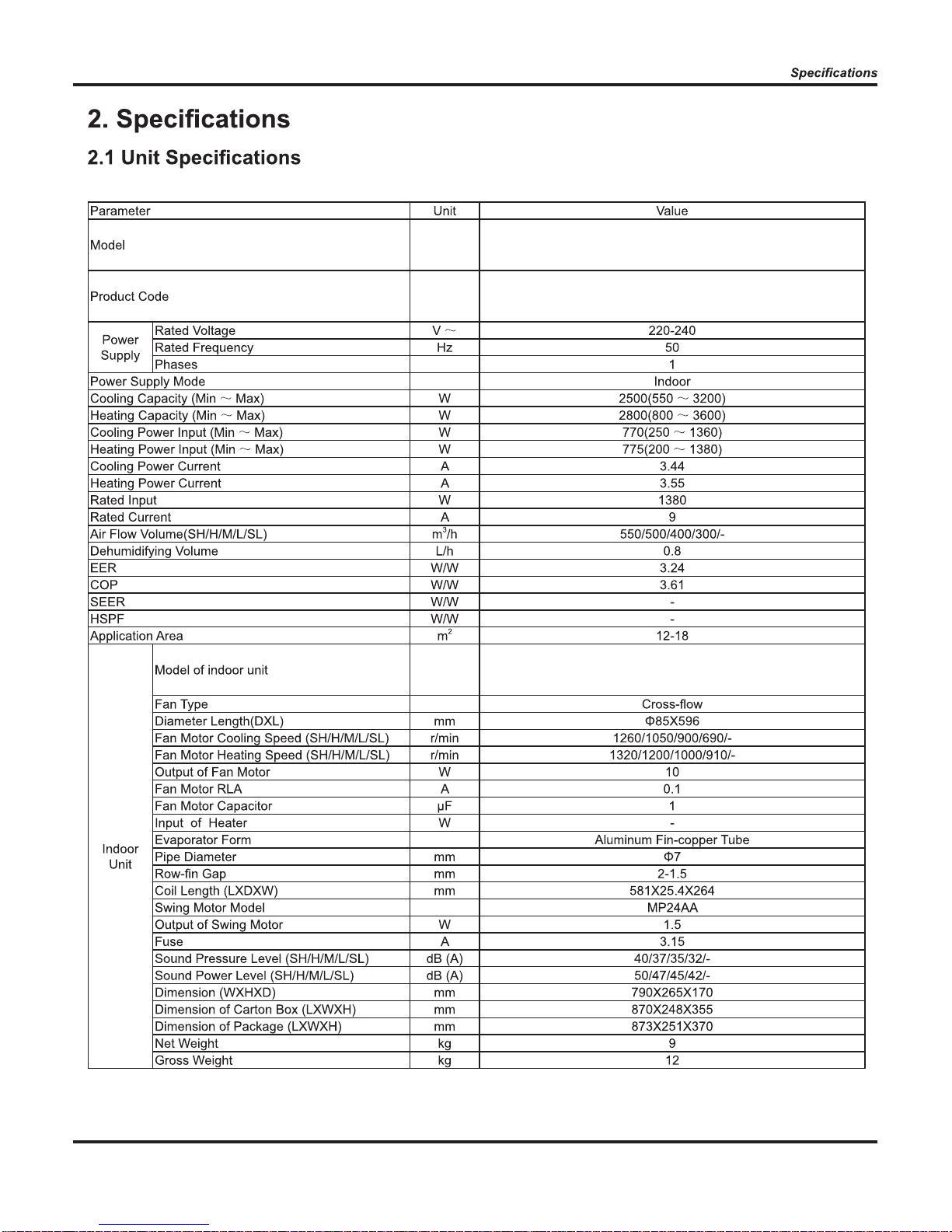
C1VI - 09 / C1VO - 09
C1VI - 12 / C1VO - 12
a
b
e
2
3
3
7
7
8
8
9
10
11
12
12
12
14
16
16
19
24
24
26
27
28
Simply
29
30
31
31
35
39
39
62
59
...............................................43
.46
..........................................................................44
. 59
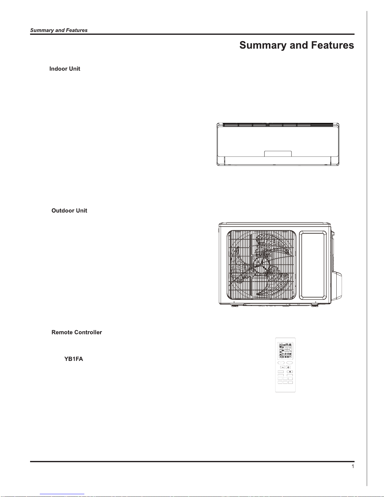
C1VI-09
C1VI-12
ON OFF
MODE
FAN
CLOCK TIMER ON
X-FAN TEMP
TIMER OFF
TURBO SLEEP LIGH T
C1VO-09
C1VO-12

2
C1VI - 09 / C1VO - 09
C1VI - 09 / C1VO - 09
C1VI - 09
3

C1VO - 09
4

C1VI - 12 / C1VO - 12
C1VI - 12 / C1VO - 12
C1VI - 12
5

C1VO - 12
6
a
12K
09K
Current(A)
757060504030
1
2
3
4
5
6
7
Compressor Speed (rps)
20
12K
09K
Current(A)
757060
50
4030
1
2
3
4
5
6
7
Compressor Speed (rps)
20
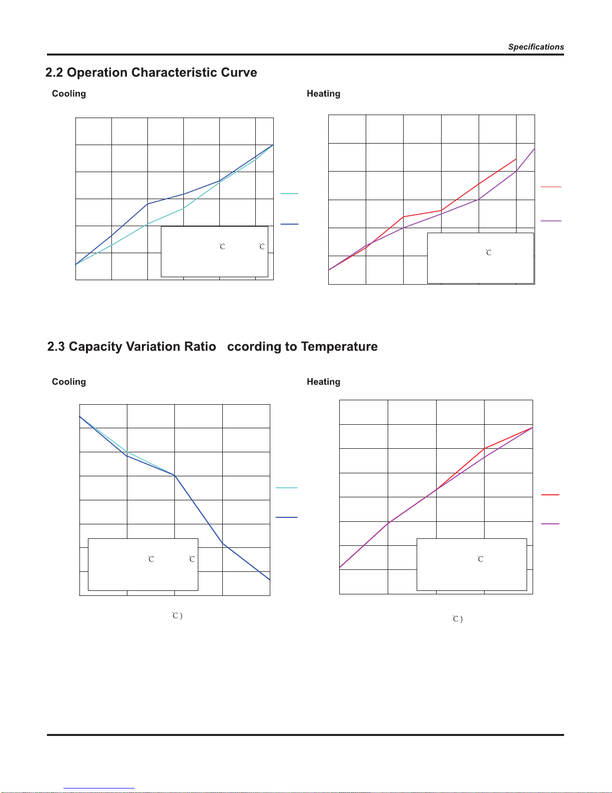
Condition Cooling
Indoor:DB26.7
WB19.4
Indoor air flow: Super High
Pipe length:5m
Condition Heating
Indoor:DB21.1
Indoor air flow: Super High
Pipe length:5m
09K
12K
Capacity ratio(%)
110
60
1070-8
40
50
70
80
90
100
120
Outdoor temp(
-15
09K
12K
Capacity ratio(%)
110
60
48423835
40
50
70
80
90
100
120
Outdoor temp(
32
Condition Heating
Indoor:DB21.1
Indoor air flow: Super High
Pipe length:5m
Condition Cooling
Indoor:DB26.7
WB19.4
Indoor air flow: Super High
Pipe length:5m
7
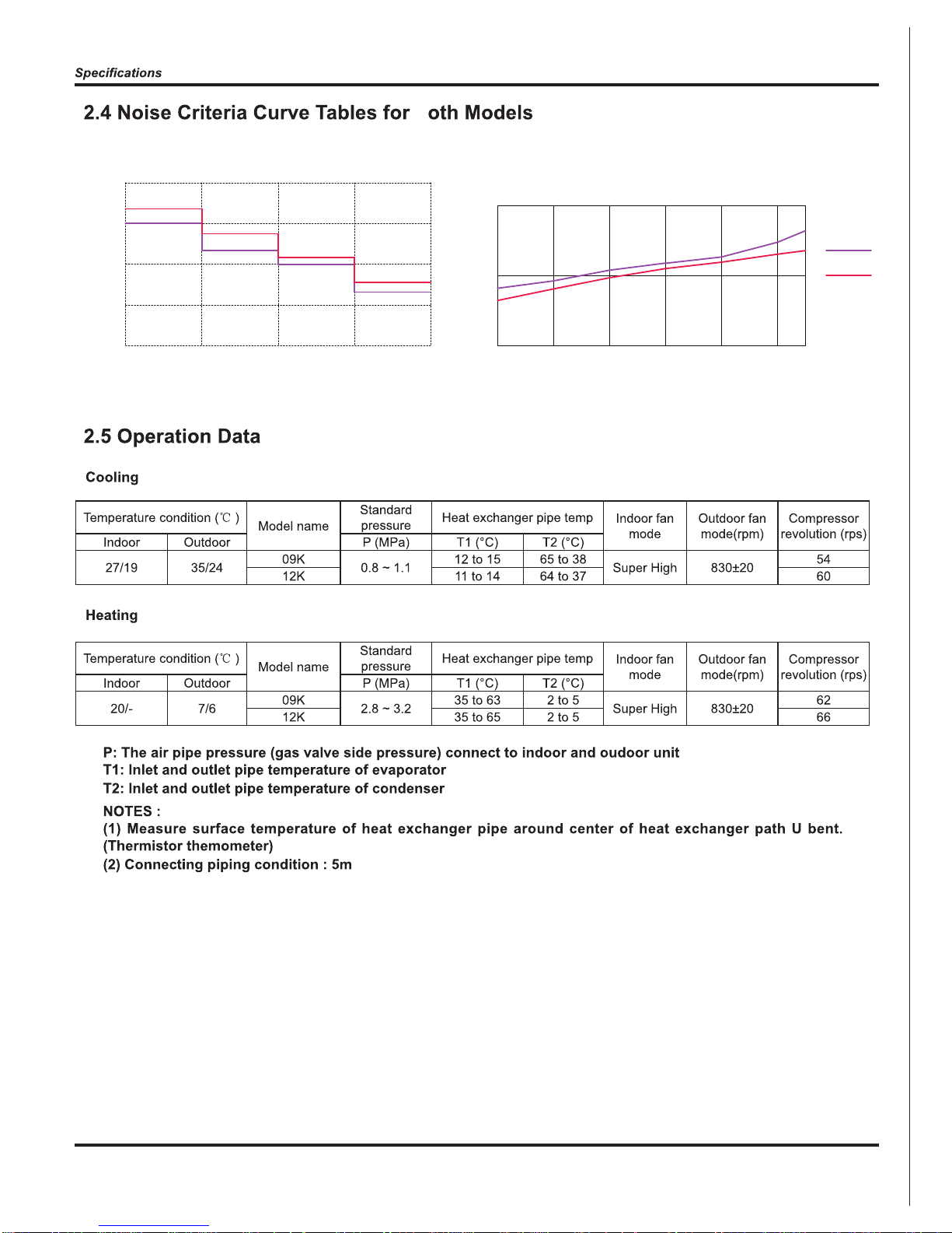
Indoor side noise when blowing
Outdoor side noise when Compressor speed changed
Compressor Speed(rps)
706050403020
45
50
55
Noise/dB(A)
75
09K
12K
Indoor fan motor rotating speed
LowMiddleHighSupper High
25
30
35
40
45
Noise/dB(A)
b
8
9
10
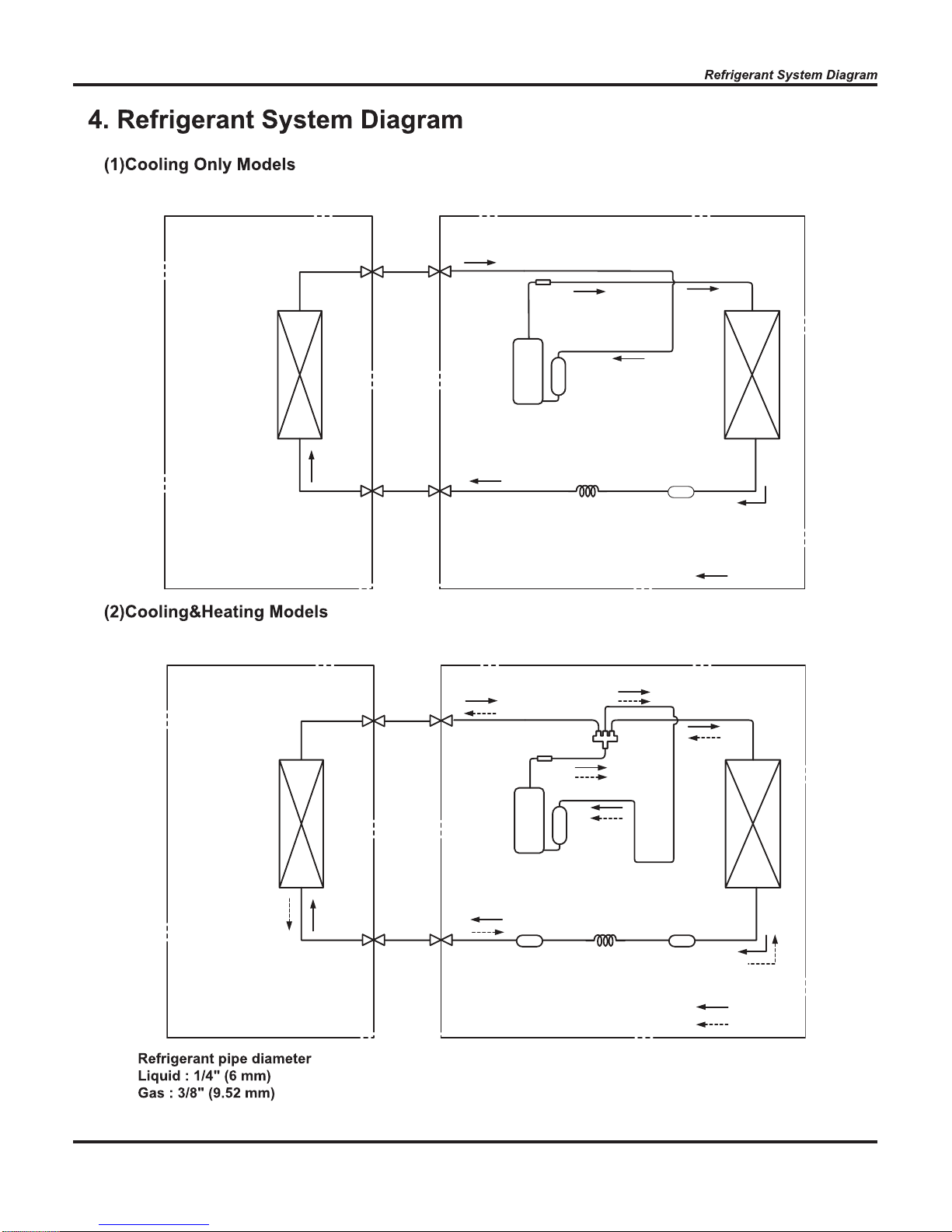
TINU ROODTUOTINU ROODNI
HEAT
EXCHANGE
(EVAPORATOR)
HEAT
EXCHANGE
(CONDENSER)
COMPRESSOR
GAS SIDE
3-WAY VALVE
LIQUID SIDE
2-WAY VALVE
COOLING
Accumlator
Discharge
Suction
Muffler
Strainer
Capillary
TINU ROODTUOTINU ROODNI
HEAT
EXCHANGE
(EVAPORATOR)
HEAT
EXCHANGE
(CONDENSER)
COMPRESSOR
GAS SIDE
3-WAY VALVE
LIQUID SIDE
2-WAY VALVE
COOLING
HEATING
Accumlator
Discharge
Suction
Muffler
4-Way valve
reniartSreniartS
Capillary
11
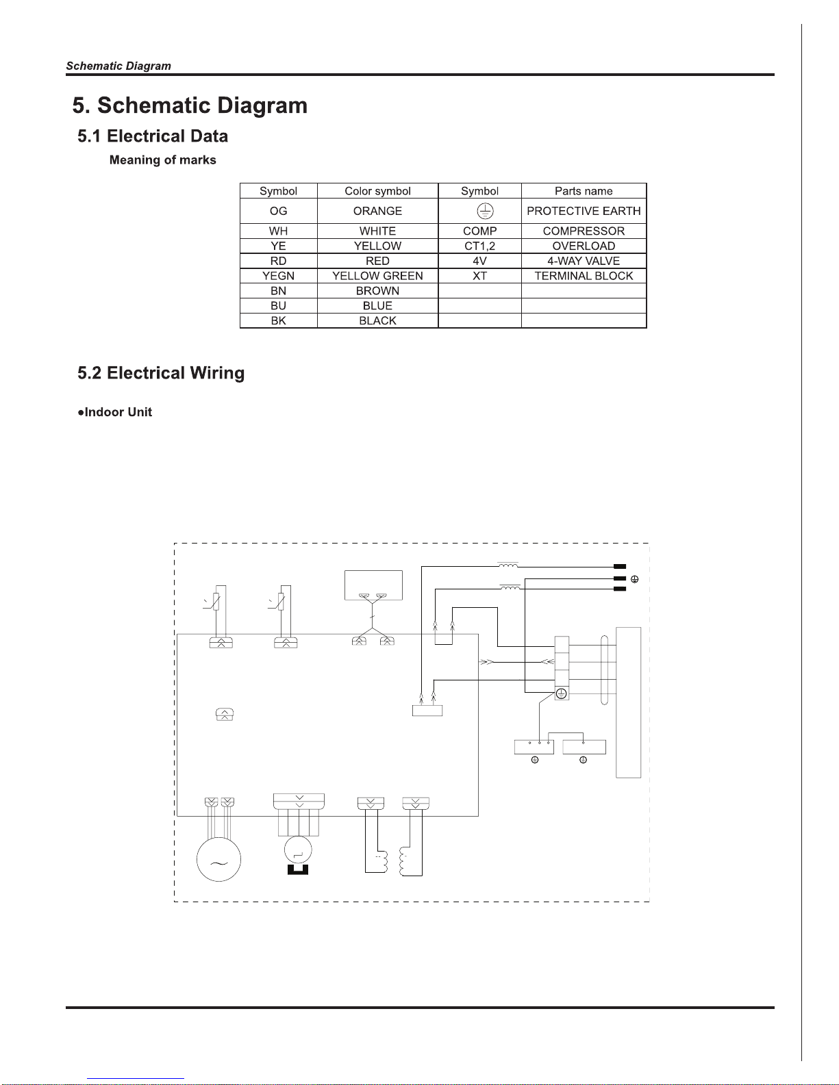
0 0
RT1 RT2
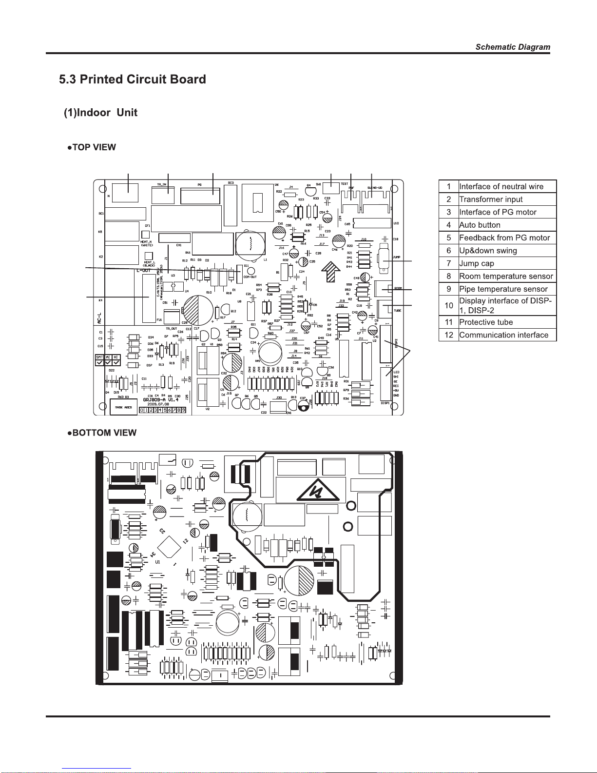
JUMP
CAP
TEM.SENSOR
ROOM
TUBE
TEM.SENSOR
FAN MOTOR
SWING MOTOR(U.D)
AP2
SWING-UD
K4
TUBEROOM
AC-L
PG
PGF
TR_OUT
TR_IN
TC
TRANSFORMER
13
DISPLAY
AP1
CN1
CN2
DISP2
DISP1
M2
M1
PE PE
L1
L1
I
II
L-OUT
ELECTRIC BOX
EVAPORATOR
XT1
W4BU
W3BN
N(1)
OUTDOOR UNIT
2
3
COM-OUT
W1YEGN
W2YEGN
N
W5BK
L
N
BU
YEGN
BN
BN
BU
YEGN
BK
POWER
12
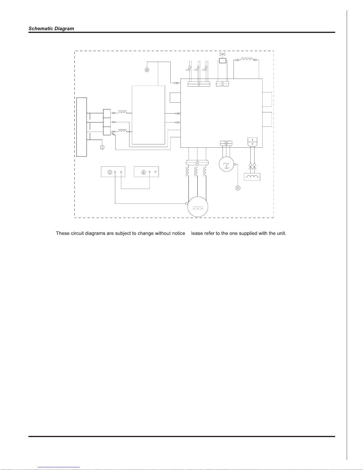
. P
XT
3
2
PE
0
RT1
0
RT2
RT3
0
L
COMP.
PE PE
AP1
AP2
L1
L1
PE
M
TEM.SENSOR
TUBE
OUTROOM
TEM.SENSOR
EXHUAST
TEM.SENSOR
YEGN
W9
YEGN
YEGN
YEGN
YEGN
FAN MOTOR
COMP
BU
YE
RD
YEGN
CT1,2
RD
BN
BU
BU
BN
BN
BN
BU
BU YE
RD
BN
BK
BU
BU
BN
BK
BU
W3
W2
W1
W24
W20
W19
W16
W17
W18
W13
W14
W15
W22
PE
W10 W11
W8
W23
W5
W6
W12
W21
L2
ELECTRIC BOX
MID.ISOLATION SHEET
AC-L5
AC-L4
AC-L
AC-N
COMU
AC-N3
U V W
OFAN
OVC-COMP
AC-N2
AC-N1
AC-L3
AC-L2
LX1-2
LX1-1
CN2
E
AC-L
N
AC-L1
N1
PE
R(W)
S(U)
C(V)
E
N(1)
I
N
D
O
O
R
U
N
I
T
4V
4V
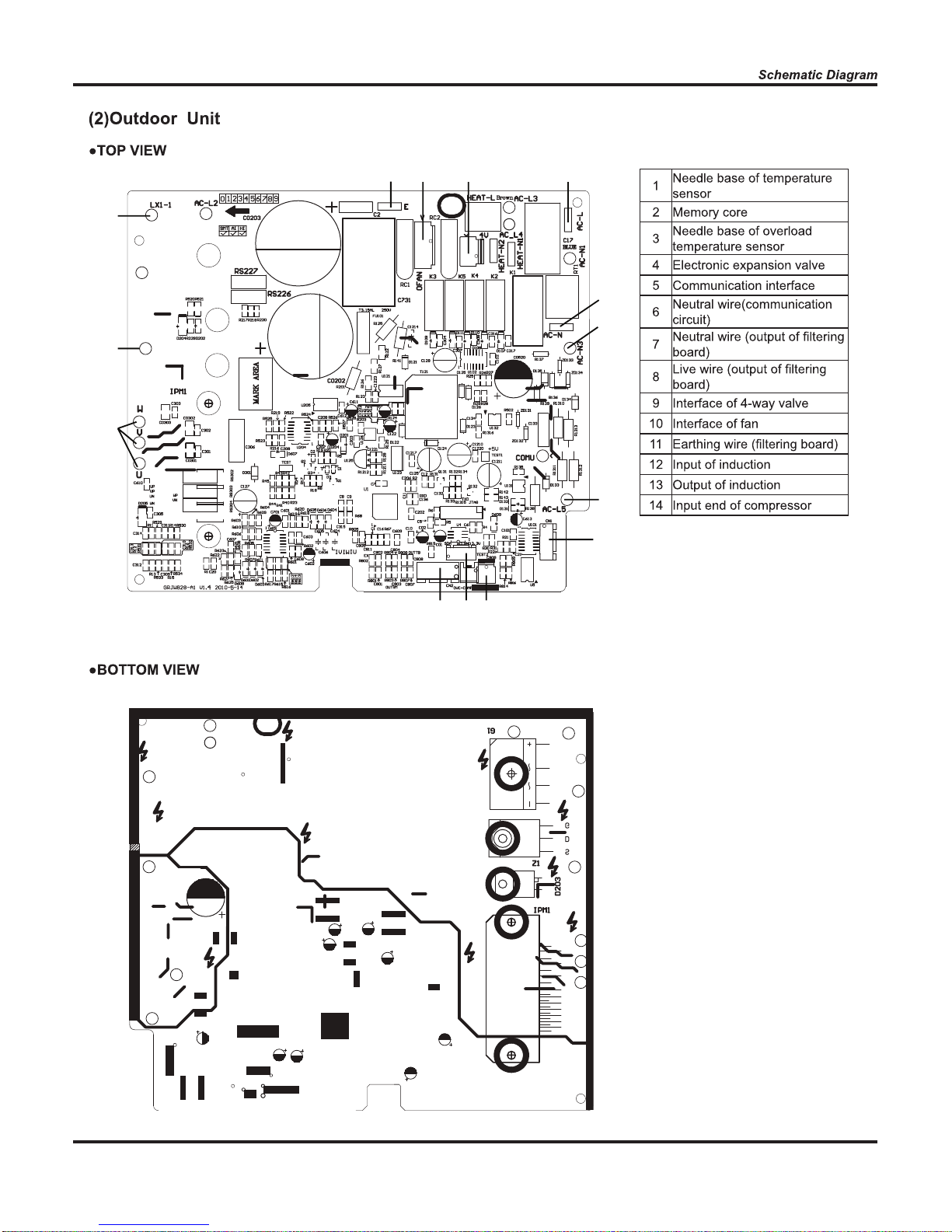
Outdoor Unit
13
1 2 3
4 5 6
7
8
9
10
11
12
14
11 10 9 8
7
6
13
12
14
5
4
32
1
15
1
7
8
4
3
5
6
11
13
12
16
17
18
10
14
9
15
2
2
8
9
10
3
4
11
12
7
6
13
14
5
1
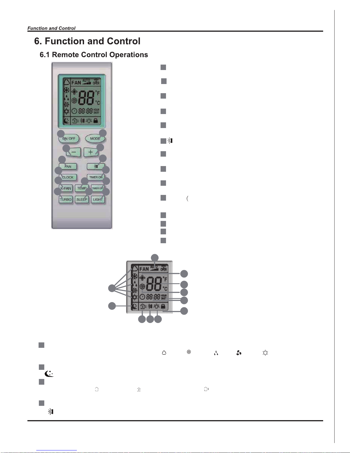
ON/OFF
Press it to start or stop operation.
MODE
Press it to select operation mode (AUTO/COOL/DRY/FAN/HEAT).
+
Press it to increase temperature setting.
-
Press it to decrease temperature setting.
FAN
Press it to set fan speed.
Press it to set swing angle.
TIMER ON
Press it to set auto-on timer.
TIMER OFF
Press it to set auto-off timer.
CLOCK
Press it to set clock.
X-FAN X-FAN is the alternative expression of BLOW for the purpose
of understanding.)
TEMP
TURBO
SLEEP
LIGHT
Press it to turn on/off the light.
171518 19
16
20
21
23
24
22
25
MODE icon:
If MODE button is pressed, current operation mode icon (AUTO), ( COOL), (DRY), (FAN) or (HEAT is only for heat
pump models) will show.
SLEEP icon :
is displayed by pressing the SLEEP button. Press this button again to clear the display.
TEMP icon:
Pressing TEMP button, (set temperature), (indoor ambient temperature), (outdoor ambient temperature) and blank is
displayed circularly.
Up & down swing icon:
is displayed when pressing the up & down swing button. Press this button again to clear the display.
16
20
21
22
23
24
25
1
2
3
4
5
6
19
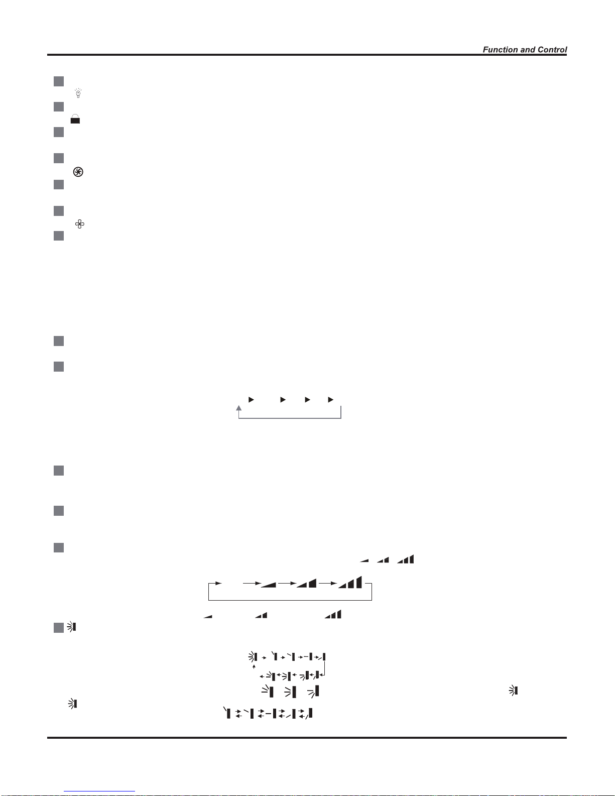
LIGHT icon:
is displayed by pressing the LIGHT button.Press LIGHT button again to clear the display.
LOCK icon:
is displayed by pressing "+" and “-” buttons simultaneously.Press them again to clear the display.
SET TIME display:
After pressing TIMER button, ON or OFF will blink.This area will show the set time.
TURBO icon:
is displayed when pressing theTURBO button.Press this button again to clear the display.
DIGITAL display:
This area will show the set temperature. In SAVE mode,"SE" will be displayed. During defrosting operation, “H1” will be displayed.
X-FAN icon:
is displayed when pressing the X-FAN button. Press this button again to clear the display.
FAN SPEED display:
Press FAN button to select the desired fan speed setting(AUTO Low-Med-High).Your selection will be displayed in the LCD windows,
except the AUTO fan speed.
ON/OFF:
Press this button to turn on the unit. Press this button again to turn off the unit.
MODE:
Each time you press this button,a mode is selected in a sequence that goes from AUTO, COOL,DRY, FAN, and HEAT *, as the
following:
*Note: Only for models with heating function.
After energization, AUTO mode is defaulted. In AUTO mode, the set temperature will not be displayed on the LCD, and the unit will
automatically select the suitable operation mode in accordance with the room temperature to make indoor room comfortable.
+ :
Press this button to increase set temperature. Hold it down for above 2 seconds to rapidly increase set temperature. In AUTO mode,
set temperature is not adjustable.
-:
Press this button to decrease set temperature. Hold it down for above . 2 seconds to rapidly decrease set temperature. In AUTO
mode, set temperature is not adjustable.
FAN :
This button is used for setting fan speed in the sequence that goes from AUTO, , , to then back to Auto.
Press this button to set up & down swing angle, which circularly changes as below:
This remote controller is universal. If any command , or is sent out, the unit will carry out the command as
indicates the guide louver swings as:
AUTO
COOL DRY FAN HEAT*AUTO
Low speed Medium speed High speed
OFF
17
8
9
10
11
12
13
14
15
16
7
TIMER ON:
Press this button to initiate the auto-ON timer. To cancel the auto-timer program, simply press this button again. After pressing this
button, disappears and "ON" blinks . 0 0:00 is displayed for ON time setting. Within 5 seconds, press + or - button to adjust the
time value. Every press of either button changes the time setting by 1 minute. Holding down either button rapidly changes the time
setting by 1 minute and then 10 minutes. Within 5 seconds after setting, press TIMER ON button to confirm.
TIMER OFF:
Press this button to initiate the auto-off timer. To cancel the auto-timer program, simply press the button again.TIMER OFF setting is
the same as TIMER ON.
CLOCK :
Pressing CLOCK button, blinks. Within 5 seconds, pressing + or - button adjusts the present time. Holding down either button
above 2 seconds increases or decreases the time by 1 minute every 0.5 second and then by 10 minutes every 0.5 second. During
blinking after setting, press CLOCK button again to confirm the setting, and then will be constantly displayed.
X-FAN:
Pressing X -FAN button in COOL or DRY mode,the icon is displayed and the indoor fan will continue operation for 10 minutes in
order to dry the indoor unit even though you have turned off the unit.
After energization, X-FAN OFF is defaulted. X-FAN is not available in AUTO, FAN or HEAT mode.
TEMP:
Press this button, could select displaying the indoor setting temperature or indoor ambient temperature.When the indoor unit firstly
power on it will display the setting temperature, if the temperature's displaying status is changed from other status to" ",displays
the ambient temperature, 5s later or within 5s, it receives other remote control signal that will return to display the setting temperature. if the users haven't set up the temperature displaying status,that will display the setting temperature.
TURBO:
Press this button to activate / deactivate the Turbo function which enables the unit to reach the preset temperature in the shortest
time. In COOL mode, the unit will blow strong cooling air at super high fan speed. In HEAT mode, the unit will blow strong heating air
at super high fan speed.
SLEEP:
Press this button to go into the SLEEP operation mode. Press it again to cancel this function. This function is available in COOL,
HEAT (Only for models with heating function) or DRY mode to maintain the most comfortable temperature for you.
LIGHT:
Press LIGHT button to turn on the display's light and press this button again to turn off the display's light. If the light is turned on ,
is displayed. If the light is tunrned off, disappears.
Combination of "+" and "-" buttons: About lock
Press "+ " and "-" buttons simultaneously to lock or unlock the keypad. If the remote controller is locked, is displayed. In this
case, pressing any button, blinks three times.
Combination of "MODE" and "-" buttons:About switch between Fahrenheit and Centigrade At unit OFF, press "MODE" and "- "
buttons simultaneously to switch between
and .
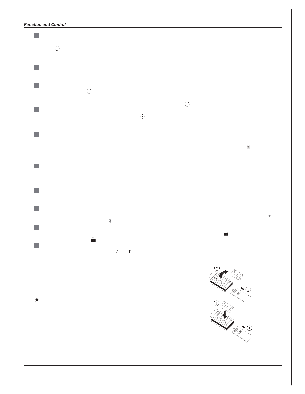
Replacement of Batteries
1.Remove the battery cover plate from the rear of the remote controller.
(As shown in the figure)
2.Take out the old batteries.
3.Insert two new AAA1.5V dry batteries, and pay attention to the polarity.
4. Reinstall the battery cover plate.
Notes:
●When replacing the batteries, do not use old or different types of batteries.
Otherwise, it may cause malfunction.
●If the remote controller will not be used for a long time,
please remove batteries to prevent batteries from leaking.
●The operation should be performed in its receiving range.
●It should be kept 1m away from the TV set or stereo sound sets.
●If the remote controller does not operate normally, please take the
batteries out and reinsert them after 30 seconds. If it still can't operate
properly, replace the batteries.
Sketch map for
replacing batteries
18

Start cooling
Stop cooling
Compresso
r
Original working state
Run
Stop
Outdoor fan
Indoor fan
T
preset
T
amb.
6 minutes 6 minutes3 minutes
T
preset
-3
Preset wind speed
When T indoor amb. =Tpreset-2 , after compressor operates at the frequency which is lower than 15Hz for
continuous 15 minutes, if Tindoor amb.=Tpreset -2
still, compressor stops operation.
When Tindoor amb.
Tpreset-3 , compressor stops operation and outdoor fan stops operation in 30s later. Indoor fan
operates at set speed.
When Tpreset-2
Tindoor amb. Tpreset, the previous operation status will be maintained.
19

(4)-10 . Toutdoor amb. -5 , Toutdoor pipe-Tcompensation Toutdoor amb.-3
(5)Toutdoor amb. -10 , Toutdoorpipe-Tcompensation Toutdoor amb.-3
(After energization, for the first defrosting, Tcompensation=0 ; if it is not first defrosting, Tcompensation is determined
by Toutdoor pipe of last time of quitting defrosting;
a. when Toutdoor pipe
2 , Tcompensation=0 ; b. when Toutdoor pipe 2 , Tcompensation=3
20

21

A
L
B
C
D
O(0
)
O(0 )
L1
A1
B1
C1
D1
heating angle
cooling angle
22

23

24

25

Space to the wall
Space to the ceiling
Space to the wall
Space to the wall
Air outlet side
Space to the floor
Above
Above
15cm Above
15cm Above
30cm Above
50cm Above
50cm Above
30cm Above
200cm Above
Above
Space to the obstruction
Air outlet side
Space to the wall
Air inlet side
The dimensions of the space necessary for correct
installation of the appliance including the minimum
permissible distances to adjacent structures
●
15cm
250
cm
300cm
26

Indoor
Outdoor
Wall pipe
Seal pad
bulge
distortion
outlet pipe of
indoor unit
insulating tube
connected
insulating tube
drain hose
outlet pipe of
indoor unit
drain hose
outlet pipe of
indoor unit
outlet pipe of
indoor unit
rubber belt
rubber belt
rubber belt
Flooded
Fig.2
Wiring Cover
outdoor unit connection
yellowgreen
brown
N(1)
black
2 3
blue
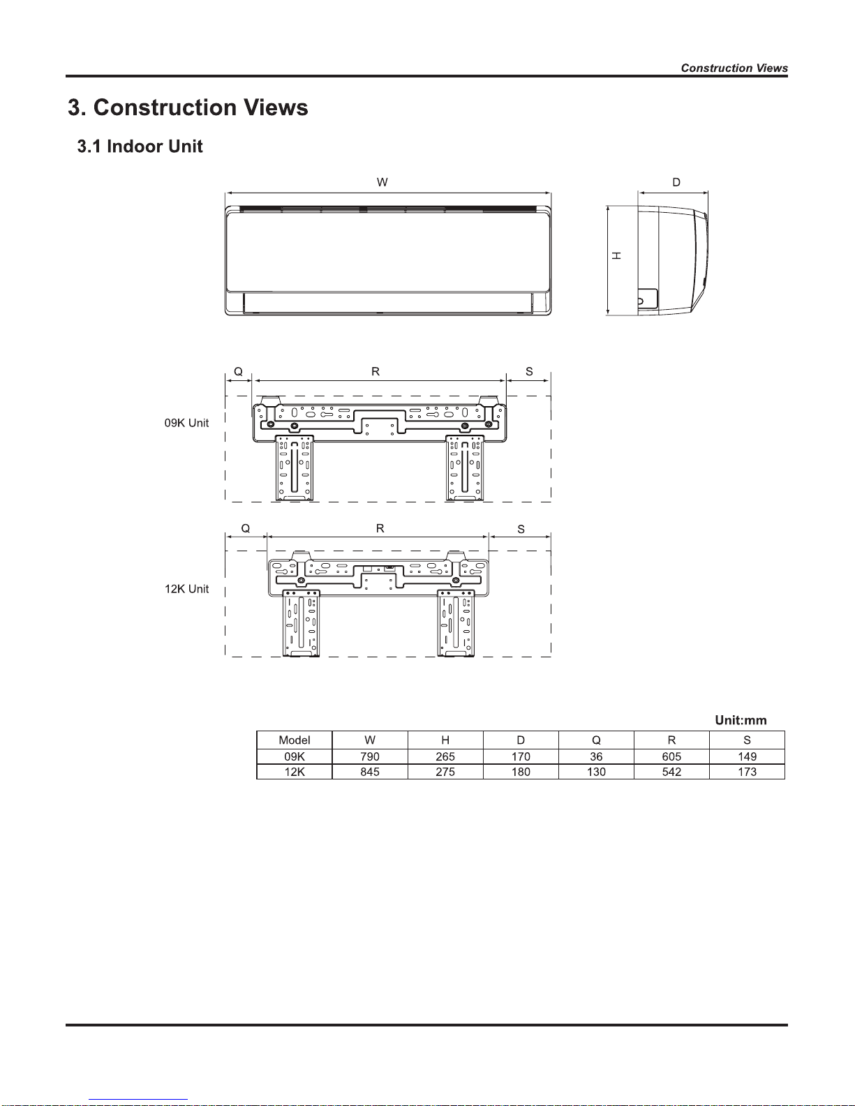
09K UNIT:
12K UNIT:
Wall
Wall
Wall
Above
150 from
the wall
Above
150 from
the wall
Wall
Wall
Wall
Above
150 from
the wall
Above
150 from
the wall
Φ55
Φ55
RightLeft
RightLeft
Φ55
Φ55
Above 150 from the ceiling
Above 150 from the ceiling
27

Fig.5
Mounting
plate
Fixing hook
Mounting
plate
Right
Right rear
Fig.4
Left rear
Left
Fig.3
Tailing 1
Tailing 2
Finally wrap it
with tape
Gas side piping
insulation
Water drainage pipe
Liquid side
Piping insulation
Gas side pipe
External connection
electric wire
Liquid side piping
Spanner
Torque
wrench
Piping
Taper nut
Indoor unit piping
Black
Blue
Yellow-green
signal control wire
N(1) 2 3
Brown
Handle
28

Fig.6
Manifold Valve
Multimeter
-76cmHg
Lo Handle
Charging hose
Manometer
Hi handle
Vacuum pump
Low pressure valve
Drain-water hole
Bottom frame
Hose (available commercially,
inner dia. 16mm)
Drain connecter
29

Fig. a
filter
Air filter
Fig. b
Fig. c
Healthy
30

40
43
42
41
39
15
14
13
12
16
17
18
19
20
21
22
23
24
38
37
36
35
34
33
32
31
30
29
28
27
11
10
9
8
7
6
5
4
3
2
26
1
25
C1VI - 09
31

C1VI - 09
32

36
33
34
37
21
15
14
13
12
16
41
17
18
19
20
23
24
25
26
27
28
29
30
31
32
38
39
40
11
10
9
8
7
6
4
5
3
1
35
22
2
C1VI - 12
33

C1VI - 12
34

1
2
3
4
5
7
8
9
10 11
13
14
15 16
17
18
192021
22
6
12
C1VO - 09
35
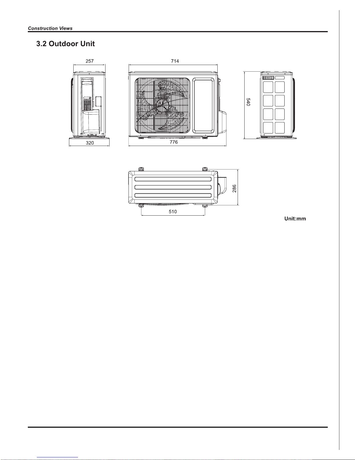
8.2 Outdoor Unit

C1VO - 09
36

1
2
3
4
5
7
8
9
10
11
12
13
14
15 16
17
18
192021
22
23
24
6
C1VO - 12
37

C1V0 - 12
38

The remote
controller does
not receive
signals (after it
is powered, the
buzzer will
sound, unless it
has
malfunction)
Trip of breaker or
blow of fuse
Air conditioner can not
start up
Measure insulation resistance
to ground to see if there is any
leakage.
The circuit or the part of the air
conditioner has malfunction.
They heat and break the insulation and lead to short circuit or
creepage. Measure the insulation resistance or eliminate the
malfunction one by one. If the
breaker itself has malfunction,
then replace the breaker.
The transformer connection is
loose or has bad contact or the
transformer has malfunction.
Fasten the wiring; measure the
output voltage of the transformer , if it is incorrect, change
the transformer.
No power
Check power supply circuit.
Power plug is not well plugged in
and poor connection.
Check if the plug is properly
plugged in and make the loose
contact firm.
Fuse of controller burnt out
The air conditioner does not
react after it is
powered ( after
the plug is
inserted, the
buzzer does not
sound and the
remote startup
has no
response)
Remote controller malfunction
Receiver loose or poor connection
Receiver is broken
Change controller fuse
Controller is broken
Check remote controller
Remote controller is short of power
Change batteries
First, press the manual switch
button AUTO,if there is no
response,check based on the
above methods. If it runs normally after pressing the button,
check again whether the installation position and the connection wire of the reception head
is correct. If it is correct,then replace the receiver or the remote
controller.
Power voltage is too low
Check the voltage. If it is lower than 10% of
the rated voltage, check the cause, improve
the power supply condition and add the stabilized voltage power supply.
The breaker trips at once when it
is set to “ON”.
The breaker trips in few minutes
when it is set to “ON”.
39

Improper set of temperature
Adjust set temperature
If cooling (heating) load is
proper
Check the forecasted load of cooling (heating)
The refrigerant has leakage or is
insufficient
Check and fill the leakage, then
vacuumize it and supplement the refrigerant as required
Leakage between the high pressure and the low pressure inside the compressor
Replace the compressor
Malfunction of four-way valve Replace the four-way valve
Local block of capillary Replace the capillary
Blockage of cooling system
Judge whether the system is blocked by
observing the condensation of evaporator and the pressure value of
the high
pressure manometer and take measures
to deal with the system.
Malfunction of
refrige r an t
flow
Heat insulation for the connection
pipes of the indoor unit and the outdoor unit is bad.
Make sure that heat insulation for the thick and thin pipes
is good. Heat insulation must also be provided for the
joint andthe exposed part of the copper pipe .
Block of outdoor heat exchanger
Clean the dust accumulated on the surface of
the heat exchanger.
Air filter were blocked
Clean the filter
Fan speed was set too slow
To set the fan speed to high or
middle speed
Air circulation
is insufficient
Fan rotation speed becomes
low
Capacitor
damage
Motor damage
Replace the capacitor
Replace the motor
The installation position of the
outdoor unit is not appropriate.
Good ventilation must be provided for the
installation position of the outdoor unit.
The outdoor temperature is too high.
Properly install the rainproof plate or the sunproof plate. If the
maximum cool air still can not meet the requirement, it is suggested to replace the air conditioner.
Keep certain air tightness indoors, try not to use
electricalappliance with large quantity of heat
The air tightness is not enough. People
come in and out too frequently. There
are heating devices indoors.
Poor COOL(HEAT) operation
40

The indoor fan motor is burned or
breaks or has the heat protector
malfunction.
Replace the fan motor or the defective part.
Wrong connection
Make the correction connection based on
the circuit drawing.
The fan capacitor has open circuit or
is damaged.
The fan does not
run when it is set
to supply air.
Replace the fan capacitor of the same type
and same specification.
The outdoor fan motor is damaged.
Replace the fan motor
Wrong connection
Make the correct connection based on the
circuit drawing
The outdoor fan capacitor is damaged.
Replace the fan capacitor
Malfunction of compressor
Replace the compressor
Breakage of running capacitor of
compressor
Replace the capacitor
The voltage is too low or too
high.
Manostat is recommended.
Wrong wir
e connection
Connect the circuit diagram correctly
The built-in heat protector of the
motor breaks frequently because the
motor is abnormal.
Replace the fan motor
Adjust the volume of the refrigerant
The refrigerant is not enough or is too
much.
Replace the capillary
The capillary is blocked and the temperature rises.
The compressor does not run
smoothly or is stuck. The air discharge
valve is damaged
Replace the compressor
The protector itself has malfunction. Replace the protector
The compressor is too hot
and leads to the
action of the
protector.
The protector itself has malfunction.
Use the multimeter to check whether the
contact of the compressor is on when it is
not overheated. If it is not on, then replace
the protector
In the cooling and
heating mode,
the compressor
runs, but the outdoor fan does not
run.
In the cooling
and heating
mode, the
outdoor fan
runs, but the
compressor
does not run.
41

Adjust fan location
Fan of indoor unit contacts other parts
Foreign object in indoor unit
Take out the foreign object
Adjust support washer of compressor, and
tighten loosen screws
Touch of pipeline of outdoor unit Separate the touching pipeline.
Abnormal sound
and shake
Touch of inner plates
1. Tighten connect screw.
2. Stick absorbing clay between plates.
Louver of outdoor unit touched outer
case.
Adjust location of louver.
Abnormal sound inside compressor
Change compressor
Drainage pipe blocked or broken Change drainage pipe
Re-wrap and make it tight.
Wrap of refrigerant pipe joint is not
close enough.
Water leakage
Change controller
Wire loose or wrong connection
In cool, heat
mode, the
outdoor unit
and compressor will not run.
Correctly wire according to the drawing
Improper setting of temperature
Adjust setting temp.
Controller malfunction (IC2003
broken, creepage of parallel capacitor of relay loop, relay is broken etc.)
First, check whether the connection is
wrong. If no, replace the parts
The swing fan
does not run.
The torque of the swing motor is not
enough
Wrong connection
The controller is damaged(IC2003 is
damaged, the swing relay can not
close, etc)
Compressor shakes too much
42

43

44

45

Simply
N
Y
N
Y
N
Y
N
Y
N
Y
Turn on the unit
and wait 1 minute
Use DC voltmeter
to measure the
voltage on the two
ends of electrolytic
capacitor
Voltage higher than 200V?
Fault with the voltage
testing circuit on
control panel AP1
Replace the control
panel AP1
Measure the AC voltage between
terminal
L and N on wiring board
XT(power supply)
Voltage within
210VAC~250VAC?
Shut down the power
and repair the power
supply to restore the
range
210VAC~250VAC
power on and
restart the unit
If the fault is
eliminated?
Shut down the power and wait 20 mi
nutes;
or use DC voltmeter to measure the voltage
on the two ends of capacitor , until the
voltage is lower than 20V
Check the
connection of reactor
(L in the Electrical
Wiring Diagram)
If the wiring of
reactor L
is normal?
Connect the reactor
Laccording to Electrical Wiring Diagram correctly
Re-energize and
turn on the unit
If the fault is
eliminated?
End
Replace the control
panel AP1
46

Energize and
switch on
IPM protection
occurs after the
machine has run for
a
p
eriod of time?
Use AC voltmeter
to measure the
voltage between
terminal L and N
on the wiring
board XT)
If the voltage
between terminal L
and N on wiring
board XT is within
210VAC~250VAC?
Check the supply
voltage and
restore it to
210VAC~250VAC
Voltage between
the two ends of celectrolytic
capacitor is
Restart the unit. Before
protection occurs,
use DC voltmeter to
measure the voltage
between the two
ends of electrolytic
capacitor on control
panel AP1
If the unit can
work
normally?
Please confirm:
1. If the indoor and
outdoor heat
exchangers are
dirty? If they are
obstructed by other
objects which affect
the heat exchange
of indoor and
outdoor unit.
2. If the indoor and
outdoor fans are
working normally?
3. If the environment
temperature is too
high, resulting in
that the system
pressure is too high
and exceeds the
permissible range?
4. If the charge
volume of
refrigerant is too
much, resulting in
that the system
pressure is too
high?
5. Other conditions
resulting in that the
system pressure
becomes too high.
The connection
of capacitor C2
is loose.
Reconnect the
capacitor C2 according
to Electrical Wiring
Diagram. Then,
Restart the
unit.
Stop the unit and
disconnect the power
supply. Wait 20 minutes,
or use DC voltmeter to
measure the voltage
between the two ends of
capacitor C2, until the
voltage is lower than 20V
Replace the capacitor
C2. Then, energize
and start the unit.
Replace the
control panel AP1
Take corrective actions
according to Technical
Service Manual, and
then energize and start
the unit.
If there is any
abnormality
described above?
Replace the
control panel AP1
If the connection
between AP1 and
COMP is unsecure
or the connection
order is wrong?
Connect the control panel
A
P1 and compressor
COMP correctly according
to the Electrical Wiring
Diagram. Then, energize
and start the unit.
Use ohmmeter to
measure the resistance
between the three
terminals on compressor
COMP, and compare the
measurements with the
compressor resistance on
Service Manual.
If the
resistance is
normal?
Use ohmmeter to
measure the resistance
between the two
terminals of compressor
COMP and copper tube.
Replace the
compressor
COMP
Resistance higher
than 500MΩ?
Replace the
control panel
AP1
END
Y N
Y
N
Y
If the unit can
work normallv?
Y
If the unit can
work normally?
Y
N
Y
N
If the unit can
work normally?
Y
Y
N
N
If the unit can
work
normally?
Y
Y
N
N
N
Y
higher than
250V
Remove the wires
on the two ends of
capacitor C2. Then,
use capacitance
meter to measure
the capacitor C2.
Verify as per the
Parameters Sheet.
Stop the unit and
disconnect the power
supply. Then, check
the connection of
capacitor C2
according to Electrical
Wiring Diagram.
If capacitor
C2 is failed?
Refer to the
Electrical Wiring
Diagram and check
if the connection
between AP1 and
COMP is loose and if
the connection order
is correct.
47

End
Y
N
Y
N
Y
N
Overheat and high
temperature protection
Is outdoor ambient temperature higher than 53?
20 minutes after the complete
unit is powered off.
Is heat dissipation of the indoor unit
and outdoor unit abnormal?
Normal protection, please operate
it after the outdoor ambient temperature is normalized.
Improve the heat
dissipation environment of the unit
Does the outdoor fan work normally?
1. Check if the fan terminal OFAN
is connected correctly
2. Resistance between any two
terminals is measure by an ohm
gauge and should be less than 1K
Ohm.
Replace the
control panel
AP1
Replace the fan
capacitor C1
Replace the
outdoor fan
48

Y
N
Y
N
N
Y
Y
N
Power on the unit
Is stop time of the compressor
longer than 3 minutes?
Restart it up after
3 minutes
Does startup fail?
Are the wires for the compressor connected
correctly? Is connection sequence right?
Connect the wires as
per the connection
diagram
Replace the control panel AP1
If the fault is eliminated?
Replace the
compressor
End
49

Out of step occurs once the
unit is powered on.
Is stop time of the
compressor longer than
3 minutes?
Are the wires for the compressor connected
correctly? Is connection sequence right?
Is the connection made in clockwise
direction?
Connect the
wires correctly
Replace the control
panel AP1
If the fault is eliminated?
Replace the
compressor
End
Out of step occurs in
operation
Is the outdoor fan working
normally?
Is the outdoor unit blocked
by foreign objects?
Replace the
control panel AP1
If the fault is eliminated?
Replace the
compressor
End
Check if the fan terminal
OFAN is connected correctly
Remove foreign objects
Replace the fan
capacitor C1
Replace the
outdoor fan
50

20 minutes after the
complete unit is
powered off
Is the terminal FA for the
electronic expansion valve
connected correctly?
Connect the
wires correctly
Resistances between the first four pins
close to the terminal hole and the fifth
pin are almost the same, less than 100
ohm.
Replace the electronic
expansion valve
If the fault is eliminated?
If the fault is eliminated?
Replace the
control panel
AP1
Coolant leakage, refilling
the coolant
End
51

Y
Y
N
N
N
N
N
N
Y
Y
Y
Start
Check wiring of the
reactor (L) of the
outdoor unit and the
PFC capacitor
Whether there is any
damage or
short-circuit?
Replace it as per the
wiring diagram and
reconnect the wires
If the fault is eliminated?
Remove the PFC capacitor
and measure resistance
between the two terminals.
Is the resistance around zero?
The capacitor is
short circuited and
the capacitor
should be replaced
Restart the unit
If the fault is eliminated?
Disconnect the terminals for the
reactor and measure the resistance
between the two terminals of the
reactor by an ohm gauge
Whether there is any damage
or short-circuit?
Replace the reactor
Restart the unit
If the fault is eliminated?
Replace the control
panel AP1
End
Y
52

Y
N
Y
N
N
Y
N
N
Y
N
Y
N
Y
Y
Start
Did the equipment operate
normally before the failure
occurs?
The AP1 voltage
detection circuit
is at fault
Check wiring inside of
the indoor and outdoor
units
Are wires broken?
Check the communication
circuit of the outdoor unit
If the fault is eliminated?
The communication
circuit is abnormal
Replace the main board
of
the indoor unit
End
If the fault is eliminated?
Replace the main board
AP1 of the outdoor unit
If the fault is eliminated?
Is the connection right?
Check the wiring of the indoor and
outdoor units with reference to the
wiring diagram
Correctly connect the
corresponding wires for
the indoor and outdoor
units with reference to
the wiring diagram
53

54

Y
Y
Y
Y
Y
N
N
N
N
Start
Measure voltage at the
Test 10 position as
shown in the diagram
with a voltmeter
Value jumping
Measure voltage at the
Test 15 position as
shown in the diagram
with a voltmeter
Value jumping
Measure voltage at the
Test 11 position as
shown in the diagram
with a voltmeter
Value jumping
Measure voltage at the
Test 12 position as
shown in the diagram
with a voltmeter
Value jumping
The communication
circuit of the outdoor
unit is normal
End
Fault with
outdoor unit
55

56

57

58

59

60

61

2
Handle
2. Remove top cover
1.Remove big handle
Top panel
1 Before disassembly.
Remove the connection screw fixing the big
handle and then remove the handle.
Remove connection screws connecting the
top cover plate with the front panel and the
right side plate, and then remove the top
panel.
62

3.Remove grille and front panel
4.Remove axial flow blade
5.Remove right side plate
Remove connection screws between the front grille
and the front panel. Then remove the front grille.
Remove connection screws connecting the front
panel with the chassis and the motor support, and
then remove the front panel.
Remove the nut fixing the blade and then
remove the axial flow blade.
Remove connection screws connecting the right
side plate with the valve support and the electric
box. Then remove the right side plate.
Grille
Panel
Axial flow blade
Right side plate
63

Remove the 2 screws fixing the cover of electric box. Lift to remove the cover. Loosen the
wire and disconnect the terminal. Lift to remove the electric box assy.
6.Remove electric box assy
Electric box assy
Unscrew the fastening nut of the 4-way Valve
Assy coil and remove the coil. Wrap the 4way Valve Assy with wet cotton and unsolder
the 4 weld spots connecting the 4-way Valve
Assy to take it out.(Note: Refrigerant should
be discharged firstly.) Welding process
should be as quickly as possible and keep
wrapping cotton wet all the time. Be sure not
to burn out the lead-out wire of compressor.
7.Remove 4-way valve assy
8.Remove capillary sub-assy
Unsolder weld point of capillary Sub-assy,
valve and outlet pipe of condensator. Then
remove the capillary Sub-assy. Do not block
the capillary when unsoldering it. (Note: before unsoldering,discharg
e refrigerants
completely)
4-way Valve Assy
Capillary Sub-assy
64

Remove the 4 tapping screws fixing the motor.
Pull out the lead-out wire and remove the
motor. Remove the 2 tapping screws fixing
the motor support. Lift motor support to remove it.
9.Remove motor and motor support
Motor
Motor support
10.Remove clapboard sub-assy
Loosen the screws of the Clapboard Sub-Assy .
The Clapboard Sub-Assy has a hook on the
lower side. Lift and pull the Clapboard Sub-Assy
to remove.
Clapboard Sub-Assy
65

11.Remove Compressor
1 Remove the 2 screws fixing the gas valve.
Unsolder the welding spot connecting gas valve
and air return pipe and remove the gas valve.
(Note: it is necessary to warp the gas valve when
unsoldering the welding spot.) Remove the 2
screws fixing liquid valve. Unsolder the welding spot connecting liquid valve and remove the
liquid valve.
2 Remove the 3 footing screws of the compressor
and remove the compressor.
Compressor
Gas valve
Liquid valve
66

 Loading...