

INVENTOR C1VI - 18, C1VO - 18, C1VI - 24, C1VO - 24 Service Manual
C1VI - 18 / C1VO - 18
C1VI - 24 / C1VO - 24

Table of Contents
Summary and Features
1.Safety Precautions
2.Specifi cations
2.1 Unit Specifi cations
2.2 Operation Characteristic Curve
2.3 Capacity Variation Ratio According to Temperature
2.4 Operation Data
2.5 Noise Criteria Curve Tables for Both Models
3. Construction Views
3.1 Indoor Unit
3.2 Outdoor Unit
4. Refrigerant System Diagram
5. Schematic Diagram
5.1 Electrical Data
5.2 Electrical Wiring
5.3 Printed Circuit Board
6. Function and Control
6.1 Remote Control Operations
6.2 Description of Each Control Operation
7. Installation Manual
7.1 Notices for Installation
7.2 Installation Dimension Diagram
7.3 Install Indoor Unit
7.4 Install Outdoor Unit
7.5 Check After Installation and Test Operation
7.6 Installation and Maintenance of Healthy Filter
..........................................................................
1
................................................................................2
...........................................................................................3
.....................................................................................3
.................................................................7
..................................8
..........................................................................................8
............................................9
............................................................................10
...............................................................................................10
............................................................................................11
.........................................................12
............................................................................13
..........................................................................................13
.......................................................................................13
................................................................................16
........................................................................19
.....................................................................19
....................................................22
.............................................................................29
.............................................................................29
...............................................................31
.....................................................................................32
..................................................................................33
.............................................34
.........................................35

8. Exploded Views and Parts List
8.1 Indoor Unit
8.2 Outdoor Unit
9. Troubleshooting
9.1 Precautions before Performing Inspection or Repair
9.2 Confi rmation
9.3 Flashing LED of Indoor/Outdoor Unit and Primary Judgement
9.4 How to Check simply the main part
10. Removal Procedure
10.1 Removal Procedure of Indoor Unit
10.2 Removal Procedure of Outdoor Unit
....................................................
36
..............................................................................................36
...........................................................................................40
...................................................................................44
...............................44
............................................................................................45
...............45
.........................................................50
.........................................................................70
.........................................................70
......................................................79

Summary and Features
1
Outdoor Unit
C1VI18
C1VI-24
YB1FA
Remote Controller
C1VI-18
C1VI-24
Summary and Features
Indoor Unit
Safety Precautions
2
Caution
Warning
Warning
Caution
could result in
personal injury
or death.
Incorrect handling
result in
injury
, or damage to product
or property.
Incorrect handling
may
minor
Recognize the following safety information:
Installing, starting up, and servicing air conditioner can be
hazardous due to system pressure, electrical components, and
equipment location, etc.
Only trained, qualified installers and service personnel are
allowed to install, start-up, and service this equipment.
Untrained personnel can perform basic maintenance functions
such as cleaning coils. All other operations should be performed
by trained service personnel.
When handling the equipment, observe precautions in the
manual and on tags, stickers, and labels attached to the equipment. Follow all safety codes. Wear safety glasses and
work gloves. Keep quenching cloth and fire extinguisher nearby
when brazing.
Read the instructions thoroughly and follow all warnings or
cautions in literature and attached to the unit. Consult local
building codes and current editions of national as well as local
electrical codes.
All electric work must be performed by a licensed technician
according to local regulations and the instructions given in this
manual.
Never supply power to the unit unless all wiring and tubing
are completed, reconnected and checked.
This system adopts highly dangerous electrical voltage.
Incorrect connection or inadequate grounding can cause
personal injury or death. Stick to the wiring diagram and all
the instructions when wiring.
Have the unit adequately grounded in accordance with
local electrical codes.
Have all wiring connected tightly. Loose connection may
lead to overheating and a possible fire hazard.
All installation or repair work shall be performed by your dealer
or a specialized subcontractor as there is the risk of fire, electric
shock, explosion or injury.
Make sure the ceiling wall is strong enough to bear the
weight of the unit.
Make sure the noise of the outdoor unit does not disturb
neighbors.
Properly insulate any tubing running inside the room to
prevent the water from damaging the wall.
Make sure the outdoor unit is installed on a stable, level
surface with no accumulation of snow, leaves, or trash
beside.
Follow all the installation instructions to minimize the risk
of damage from earthquakes, typhoons or strong winds.
Avoid contact between refrigerant and fire as it generates
poisonous gas.
Apply specified refrigerant only. Never have it mixed with
any other refrigerant. Never have air remain in the
refrigerant line as it may lead to rupture and other hazards.
Make sure no refrigerant gas is leaking out when
installation is completed.
Should there be refrigerant leakage, the density of
refrigerant in the air shall in no way exceed its limited
value, or it may lead to explosion .
Before installing, modifying, or servicing system, main
electrical disconnect switch must be in the OFF position.
There may be more than 1 disconnect switch. Lock out and
tag switch with a suitable warning label.
Keep your fingers and clothing away from any moving parts.
Clear the site after installation. Make sure no foreign
objects are left in the unit.
Always ensure effective grounding for the unit.
Never install the unit in a place where a combustible gas
might leak, or it may lead to fire or explosion.
Make a proper provision against noise when the unit is
installed at a telecommunication center or hospital.
Provide an electric leak breaker when it is installed in a
watery place.
Never wash the unit with water.
Handle unit transportation with care. The unit should not be
carried by only one person if it is more than 20kg.
Never touch the heat exchanger fins with bare hands.
Never touch the compressor or refrigerant piping without
wearing glove.
Do not have the unit operate without air filter.
Should any emergency occur, stop the unit and disconnect
the power immediately.
1.Safety Precautions
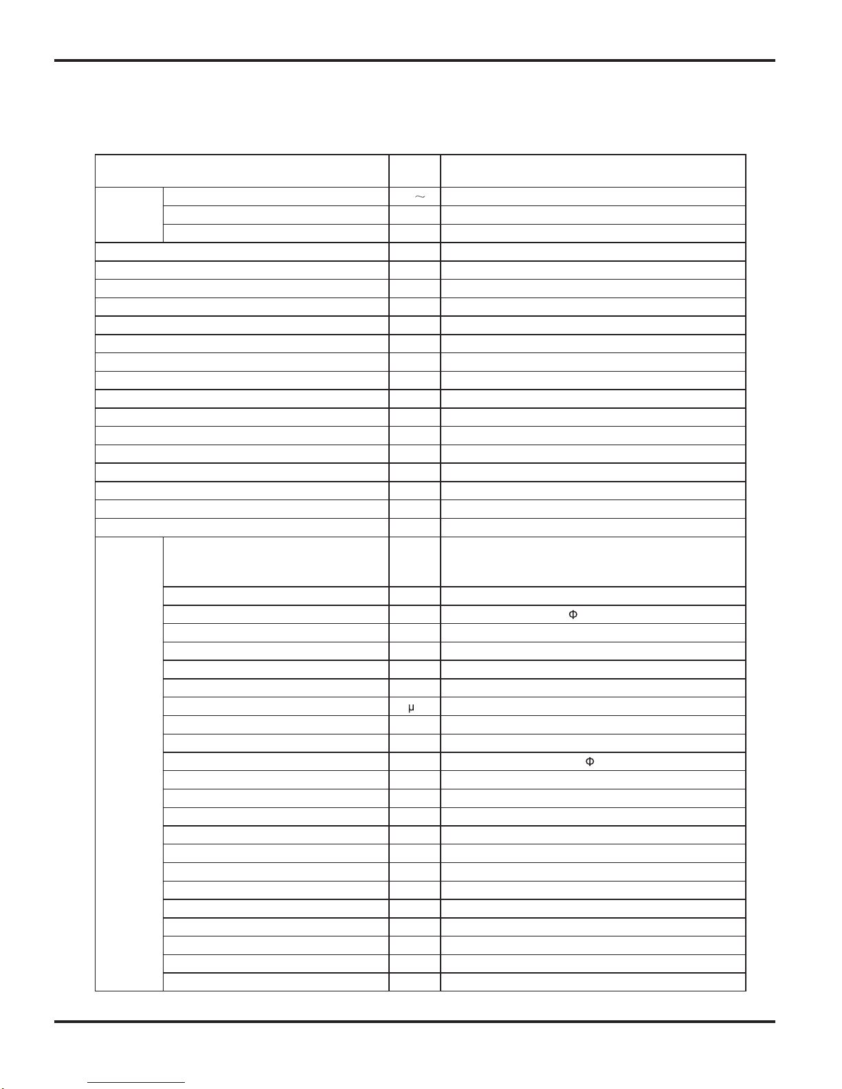
Specifi cations
3
Model
C1VI-18 / C1VO-18
Power
Supply
VegatloV detaR
220-240
05zHycneuqerF detaR
Phases 1
Power Supply Mode Outdoor
)0066~0621(5725WyticapaC gnilooC
)0086~0211(0585WyticapaC gnitaeH
)0562~083(0061WtupnI rewoP gnilooC
)0562~053(0261WtupnI rewoP gnitaeH
52.7AtnerruC rewoP gnilooC
43.7AtnerruC rewoP gnitaeH
0562WtupnI detaR
00.21AtnerruC detaR
m )LS/L/M/H/HS(emuloV wolF riA
3
-/055/056/087/058h/
2h/LemuloV gniyfidimuheD
03.3W/W REE
16.3W/W POC
/W/W REES
/W/W FPSH
maerA noitacilppA
2
23-34
Indoor Unit
Model of indoor unit C1VI-18
wo fl-ssorCepyT naF
mm )LXD(htgneL retemaiD
98X710
Fan Motor Cooling Speed(SH/H/M/L/SL) r/min 1350/1200/1050/900/Fan Motor Heating Speed(SH/H/M/L/SL) r/min 1420/1250/1150/1050/-
02WrotoM naF fo tuptuO
52.0AALR rotoM naF
Fan Motor Capacitor
5.1F
-WretaeH fo tupnI
ebuT reppoc-niF munimulA mroF rotaropavE
mmretemaiD epiP
7
4.1-2mmpaG n fi-woR
8.403X4.52X517mm )WXDXL( htgneL lioC
BV82PMledoM rotoM gniwS
3W rotoM gniwS fo tuptuO
A51.3 BCPA esuF
-/53/04/64/84 )A( Bd )LS/L/M/H/HS( leveL erusserP dnuoS
-/54/05/45/85 )A( Bd )LS/L/M/H/HS( leveL rewoP dnuoS
002X892X049mm )DXHXW( noisnemiD
083X582X0101mm)H/W/L( xoB notraC fo noisnemiD
003X383X3101mm )H/W/L(egakcaP fo noisnemiD
21gk thgieW teN
61gkthgieW ssorG
2.Specifications
2.1 Unit Specifi cations
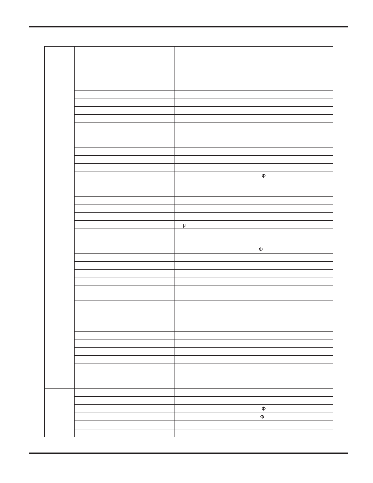
Specifi cations
4
Outdoor
Unit
C1VO-18tinU roodtuO fo ledoM
Compressor Manufacturer/Trademark MITSUBISHI ELECTRIC (GUANGZHOU)COMP
CMYGF031BNSledoM rosserpmoC
S05VPliO rosserpmoC
yratoRepyT rosserpmoC
00.72A .A.R.L
04.8A ALR rosserpmoC
5421WtupnI rewoP rosserpmoC
8756-L11TN1rotcetorP daolrevO
yrallipaCdohteM gnilttorhT
03~61CºpmeT noitarepO
54~81Cº)gnilooC( pmeT tneibmA
42~51- Cº)gnitaeH( pmeT tneibmA
ebuT reppoc-niF munimulA mroF resnednoC
mm retemaiD epiP
7
4.1-2mmpaG n fi-swoR
055X1.83X218mm )WXDXL( htgneL lioC
088mprdeepS rotoM naF
06WrotoM naF fo tuptuO
26.0A ALR rotoM naF
Fan Motor Capacitor
5.3F
Air Flow Volume of Outdoor Unit m
3
0042h/
wo fl-laixAepyT naF
mmretemaiD naF
445
gnitsorfeD citamotuAdohteM gnitsorfeD
1TepyT etamilC
Isolation I
42PInoitcetorP erutsioM
Permissible Excessive Operating Pressure
for the Discharge Side
0.3aPM
Permissible Excessive Operating Pressure
for the Suction Side
9.0aPM
-/-/45 )A( Bd )L/M/H( leveL erusserP dnuoS
-/-/46 )A( Bd )L/M/H( leveL rewoP dnuoS
873X695X998mm )DXHXW( noisnemiD
036X714X549mm)H/W/L( xoB notraC fo noisnemiD
336X234X849mm )H/W/L(egakcaP fo noisnemiD
83gk thgieW teN
34gkthgieW ssorG
A014R tnaregirfeR
02.1gkegrahC tnaregirfeR
Connection
Pipe
5mhtgneL
03m/gegrahC lanoitiddA saG
Outer Diameter Liquid Pipe mm
6
Outer Diameter Gas Pipe mm
12
01mthgieH ecnatsiD xaM
03mhtgneL ecnatsiD xaM
The above data is subject to change without notice. Please refer to the nameplate of the unit.
Specifi cations
5
Model
C1VI-24 / C1VO-24
Power
Supply
VegatloV detaR
220-240
05zHycneuqerF detaR
1sesahP
roodtuOedoM ylppuS rewoP
)0007~0041(0546WyticapaC gnilooC
)0028~0021(0007WyticapaC gnitaeH
)0052~053(5891WtupnI rewoP gnilooC
)0072~053(0391WtupnI rewoP gnitaeH
08.8AtnerruC rewoP gnilooC
65.8AtnerruC rewoP gnitaeH
0072WtupnI detaR
04.21AtnerruC detaR
m )LS/L/M/H/HS(emuloV wolF riA
3
-/055/007/008/009h/
2h/LemuloV gniyfidimuheD
52.3W/W REE
26.3W/W POC
/W/W REES
/W/W FPSH
maerA noitacilppA
2
27-42
Indoor Unit
Model of indoor unit
C1VI-24
wo fl-ssorCepyT naF
Diameter Length(DXL) mm
98X765
Fan Motor Cooling Speed(SH/H/M/L/
SL)
r/min 1250/1100/950/800/-
Fan Motor Heating Speed(SH/H/ML/
SL)
r/min 1300/1100/1000/850/-
53WrotoM naF fo tuptuO
03.0AALR rotoM naF
Fan Motor Capacitor
5.2F
-WretaeH fo tupnI
ebuT reppoc-niF munimulA mroF rotaropavE
mmretemaiD epiP
7
5.1-2mmpaG n fi-woR
9.243X4.52X567mm )WXDXL( htgneL lioC
XX53PMledoM rotoM gniwS
3W rotoM gniwS fo tuptuO
A51.3 BCPA esuF
-/93/24/74/15 )A( Bd )LS/L/M/H/HS( leveL erusserP dnuoS
-/94/25/75/16 )A( Bd )LS/L/M/H/HS( leveL rewoP dnuoS
912X513X7001mm )DXHXW( noisnemiD
313X593X3701mm)H/W/L( xoB notraC fo noisnemiD
823X893X6701mm )H/W/L(egakcaP fo noisnemiD
41gk thgieW teN
91gkthgieW ssorG
Specifi cations
6
Outdoor
Unit
C1VO-24tinU roodtuO fo ledoM
Compressor Manufacturer/Trademark MITSUBISHI ELECTRIC (GUANGZHOU)COMP
CMYGF031BNSledoM rosserpmoC
S05VPliO rosserpmoC
yratoRepyT rosserpmoC
00.72A .A.R.L
04.8A ALR rosserpmoC
5421WtupnI rewoP rosserpmoC
8756-L11TN1rotcetorP daolrevO
yrallipaCdohteM gnilttorhT
03~61CºpmeT noitarepO
54~81Cº)gnilooC( pmeT tneibmA
42~51- Cº)gnitaeH( pmeT tneibmA
ebuT reppoc-niF munimulA mroF resnednoC
mm retemaiD epiP 7
4.1-2mmpaG n fi-swoR
066X1.83X738mm )WXDXL( htgneL lioC
005/096mprdeepS rotoM naF
06WrotoM naF fo tuptuO
26.0A ALR rotoM naF
Fan Motor Capacitor
5.3F
Air Flow Volume of Outdoor Unit m
3
0023h/
wo fl-laixAepyT naF
mmretemaiD naF
520
gnitsorfeD citamotuAdohteM gnitsorfeD
1TepyT etamilC
InoitalosI
42PInoitcetorP erutsioM
Permissible Excessive Operating
Pressure for the Discharge Side
0.3aPM
Permissible Excessive Operating
Pressure for the Suction Side
9.0aPM
-/-/45 )A( Bd )L/M/H( leveL erusserP dnuoS
-/-/46 )A( Bd )L/M/H( leveL rewoP dnuoS
693X007X559mm )DXHXW( noisnemiD
537X554X6201mm)H/W/L( xoB notraC fo noisnemiD
057X854X9201mm )H/W/L(egakcaP fo noisnemiD
84gk thgieW teN
35gkthgieW ssorG
A014R tnaregirfeR
53.1gkegrahC tnaregirfeR
Connection
Pipe
5mhtgneL
03m/gegrahC lanoitiddA saG
Outer Diameter Liquid Pipe mm
6
Outer Diameter Gas Pipe mm
12
01mthgieH ecnatsiD xaM
03mhtgneL ecnatsiD xaM
The above data is subject to change without notice. Please refer to the nameplate of the unit.
Specifi cations
7
gnitaeHgnilooC
0 10 20 30 40 50 60 70 90 0 10 20 30 40 50 60 70 80 90 100 120110
80
11
10
9
8
7
6
5
4
3
2
1
0
Compressor speed (rps)
)A(tnerruC
11
10
9
8
7
6
5
4
3
2
1
0
Compressor speed (rps)
)A(tnerruC
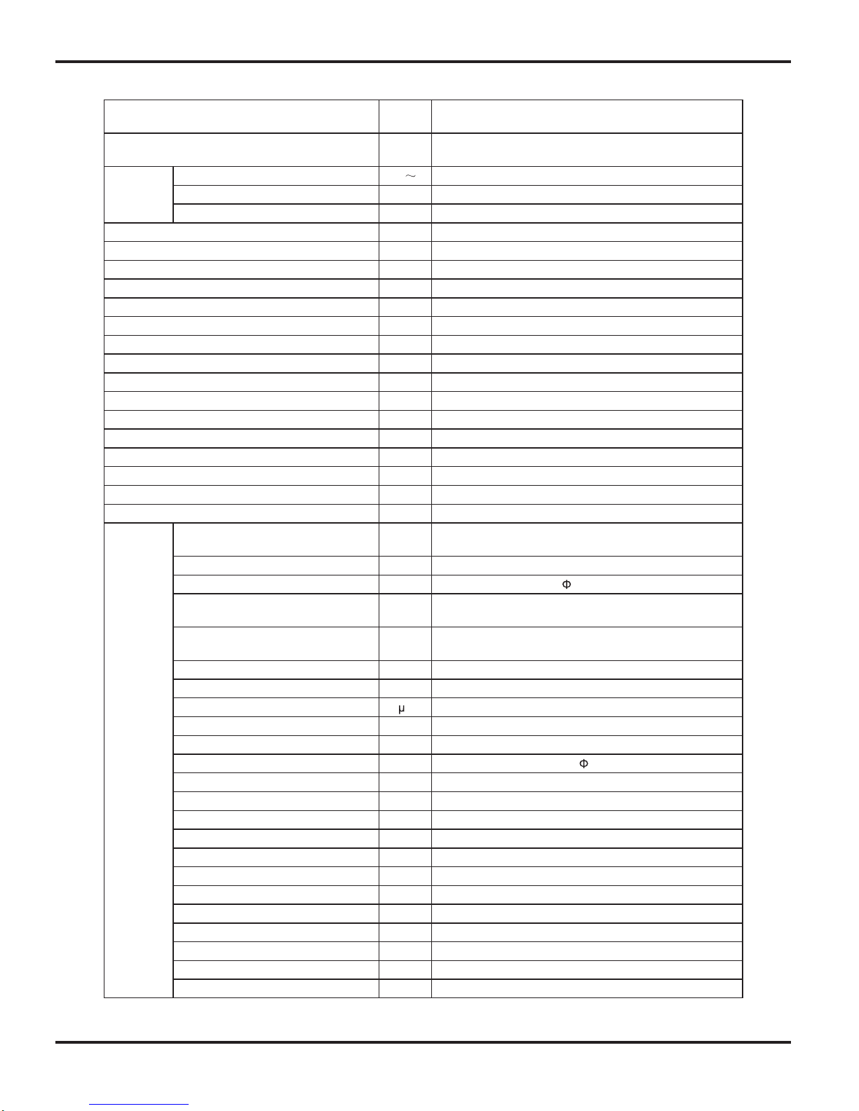
• Conditions
Indoor : DB26.7˚C/WB19.4˚C
Outdoor: DB35˚C/WB23.9˚C
Indoor air flow: Turbo
Pipe length : 5m
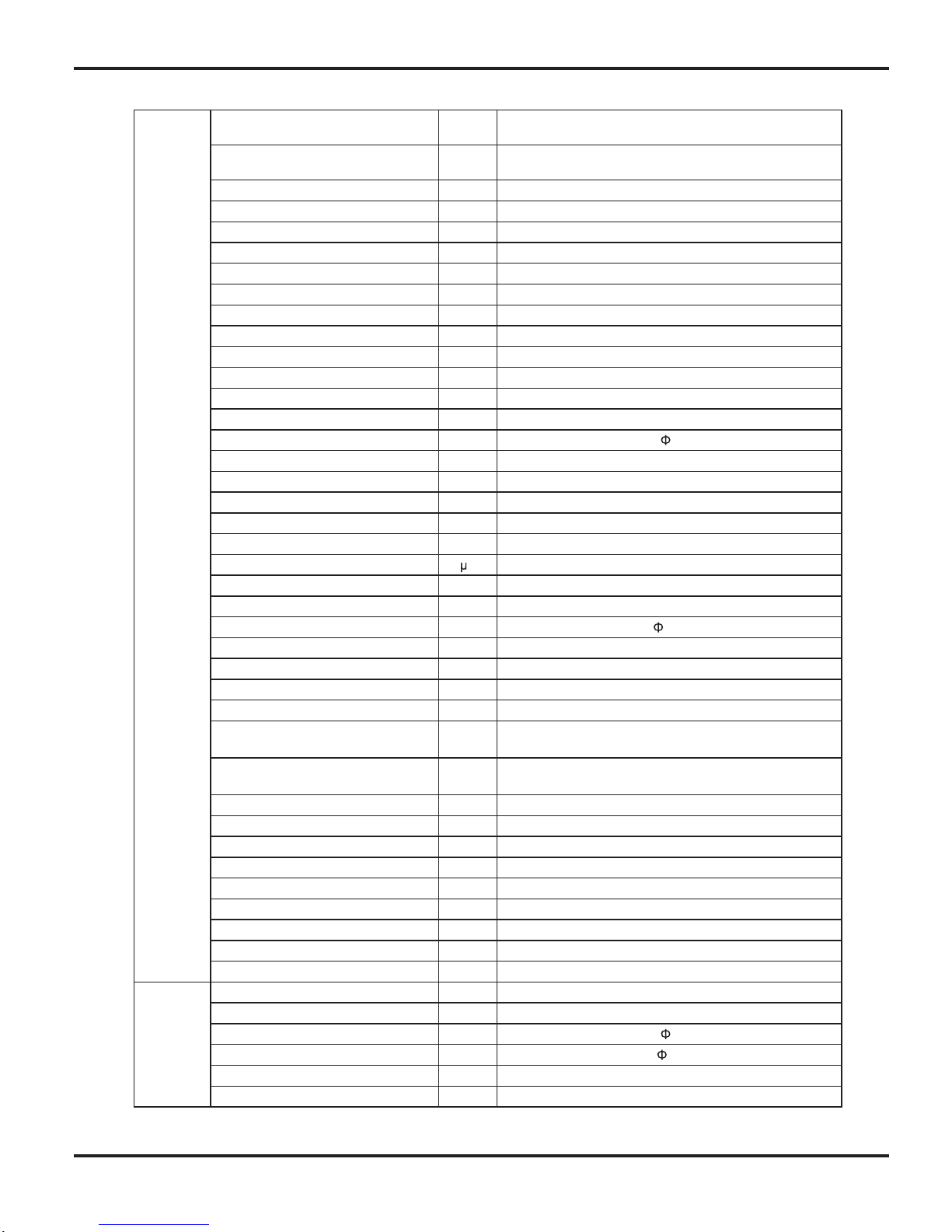
• Conditions
Indoor : DB21.1˚C/WB15.6˚C
Outdoor: DB8.33˚C/WB6.11˚C
Indoor air flow: Turbo
Pipe length : 5m
220V
230V
240V
220V
230V
240V
0 10 20 30 40 50 60 70 90 0 10 20 30 40 50 60 70 80 90 100 120110
80
11
10
9
8
7
6
5
4
3
2
1
0
Compressor speed (rps)
)A(tnerruC
11
10
9
8
7
6
5
4
3
2
1
0
Compressor speed (rps)
)A(tnerruC
• Conditions
Indoor : DB26.7˚C/WB19.4˚C
Outdoor: DB35˚C/WB23.9˚C
Indoor air flow: Turbo
Pipe length : 5m
• Conditions
Indoor : DB21.1˚C/WB15.6˚C
Outdoor: DB8˚C/WB6.11˚C
Indoor air flow: Turbo
Pipe length : 5m
220V
230V
240V
220V
230V
240V
gnitaeHgnilooC
2.2 Operation Characteristic Curve
18K
24K
Specifi cations
8
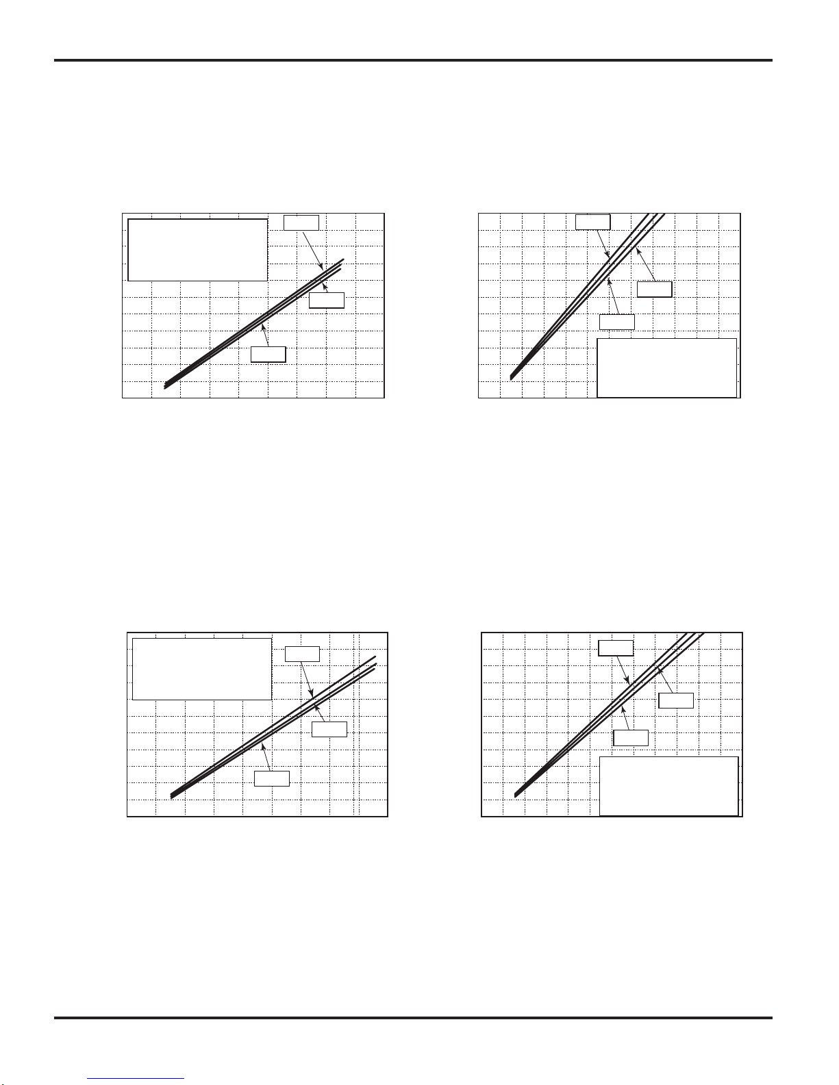
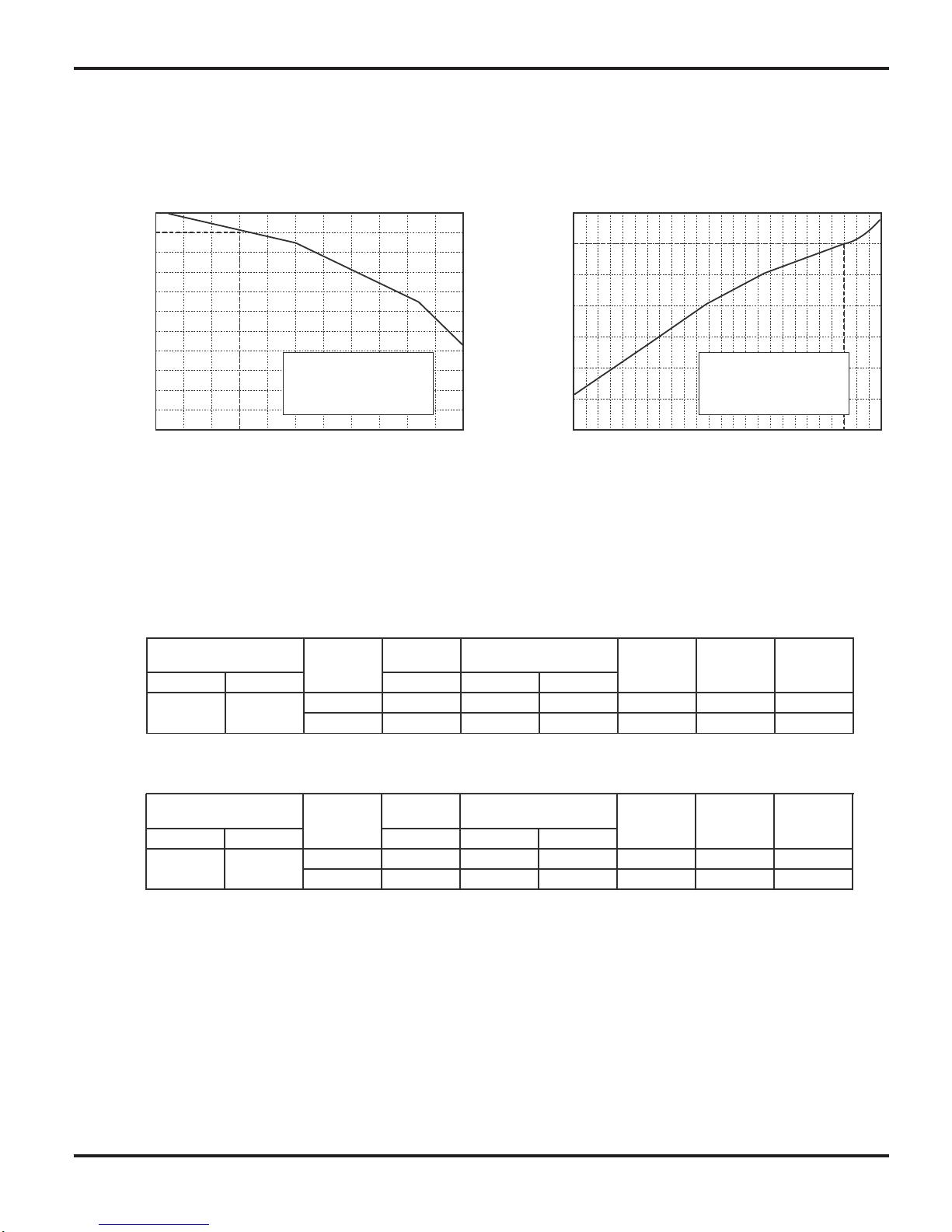
2.3 Capacity Variation Ratio According to Temperature
NOTES :
(1) T1: Inlet and outlet pipe temperature of evaporator
T2: Inlet and outlet pipe temperature of condenser
P: Pressure of air pipe connecting indoor and outdoor units(on the side of gas pipe)
(2) Measure surface temperature of heat exchanger pipe around center of heat exchanger path U bent.
(Thermistor themometer)
(3)
Connecting piping condition : 5 m
t n i looC a e H ig n g
3 2 3 3 3 4 3 5 3 6 3 7 3 8 3 9 4 3 –1 5
–10
5 0 5 7 10
4 0 4 1 42
100
105
95
90
85
80
75
70
65
60
55
50
Outdoor tem p . (˚C)
) %
(
o i t a r y t i c a p a C
110
100
90
80
70
60
50
40
Outdoor tem p . (˚C)
) % ( o i t a r y t i c a p a C
Conditions
Indoor:DB21.1
o
C /WB15.6 oC
Indoor air flow:Turbo
Pipe length:5m
Conditions
Indoor:DB26.7
o
C /WB19.4 oC
Indoor air flow:Turbo
Pipe length:5m
Cooling
Heating
Standard
pressure
Indoor Outdoor
P (MPa)
T1 (°C) T2 (°C)
18K 0.9 to 1.1 12 to 14 70 to 42 High High 62
24K 0.8 to 1.0 10 to 12 70 to 40 High High 78
Outdoor fan
mode
Compressor
Frequency
(Hz)
26.7/19.4 35/–
(°C)
Model
name
temp.
Indoor fan
mode
Standard
pressure
Indoor Outdoor
P (MPa)
T1 (°C) T2 (°C)
18K 2.2 to 2.4 70 to 37 2 to 4 High High 62
24K 2.5 to 2.7 70 to 37 0 to 3 High High 80
Outdoor fan
mode
21.1/
–
8/6.11
Temperature condition
Temperature condition
(°C)
Model
name
Heat exchanger pipe
Heat exchanger pipe
temp.
Indoor fan
mode
Compressor
Frequency
(Hz)
2.4 Operation Data

Specifi cations
9
2.5 Noise Criteria Curve Tables for Both Models
Indoor side noise when blowing
Outdoor side noise
18K
24K
60
60
60 80 100
50
50
40
40
40
30
30
20
20
20
10
0
0
Indoor Fan Motor Rotating Speed
Noice/dB(A)
low
Middle
High Super High
Compressor frequency/Hz
)A(Bd/esioN
18 24K
Constrction Views
10
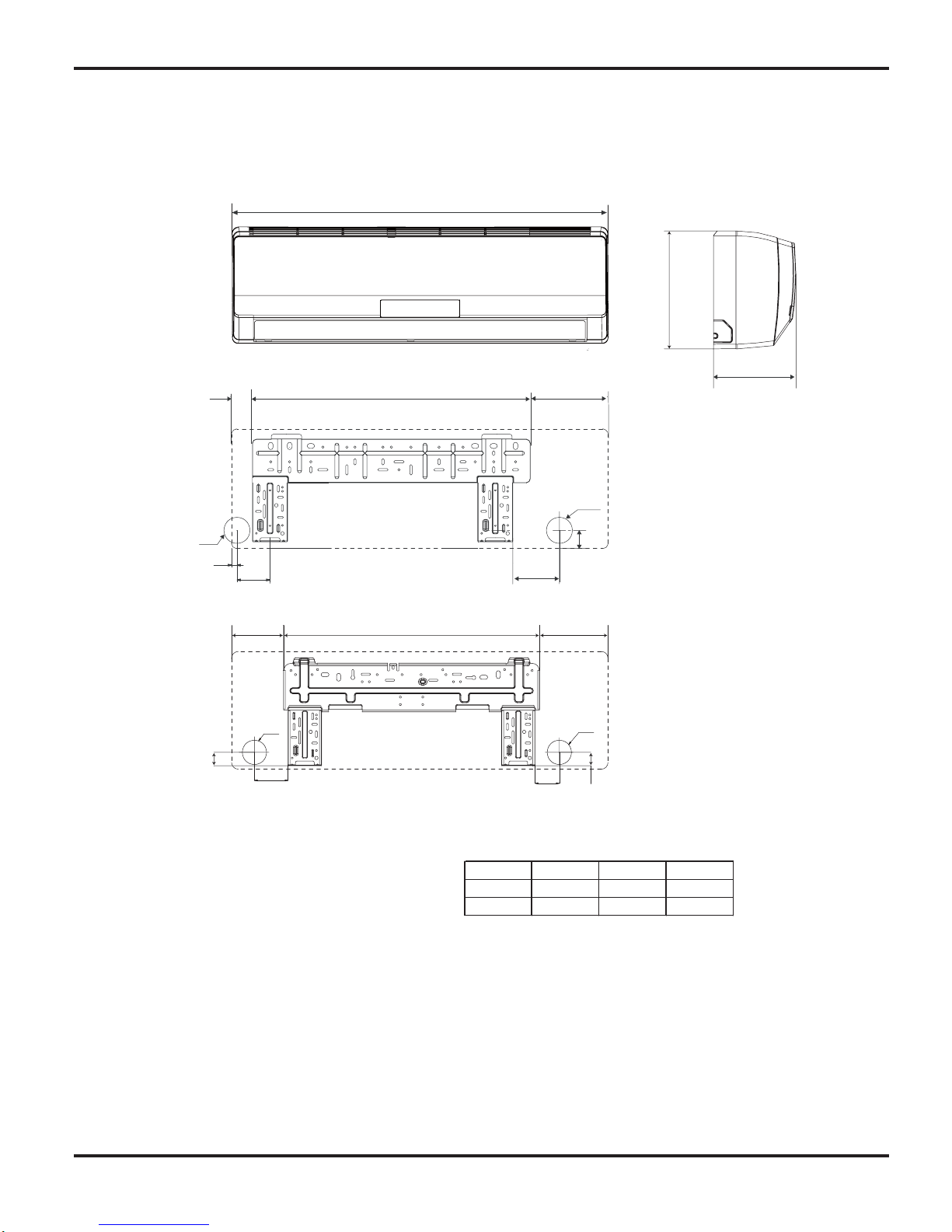
3. Construction Views
3.1 Indoor Unit
139
685
183
Φ55
Φ55
6 3
6 3
90
65
72
45
694
194
D
52
Φ55
Φ55
14
82
18K
24K
Model W H D
W
18K 940 298 200
24K 1007 315 219
Unit:mm
H
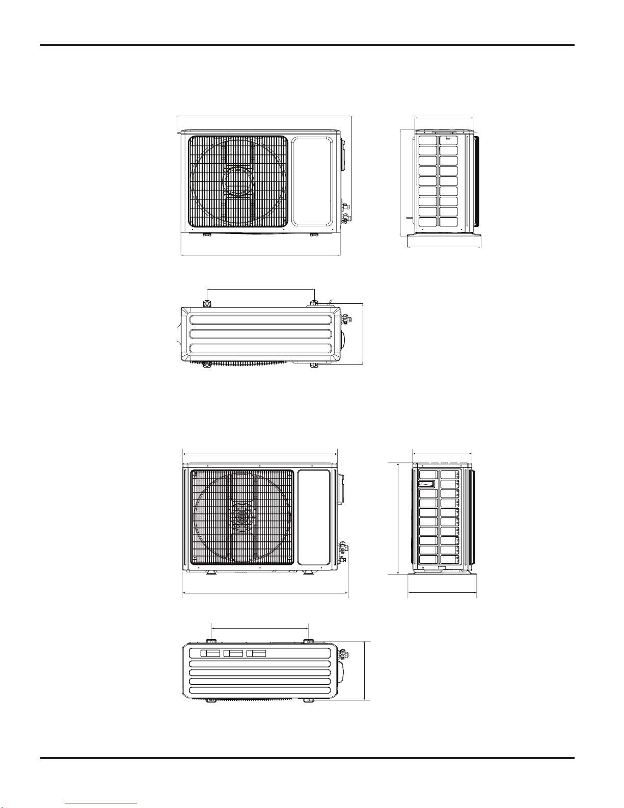
Constrction Views
11
3.2 Outdoor Unit
18K
24K
955
560
043 798
396
3 6 4
7 0 0
899
818
695
378
303
343
550
Refrigerant System Diagram
12
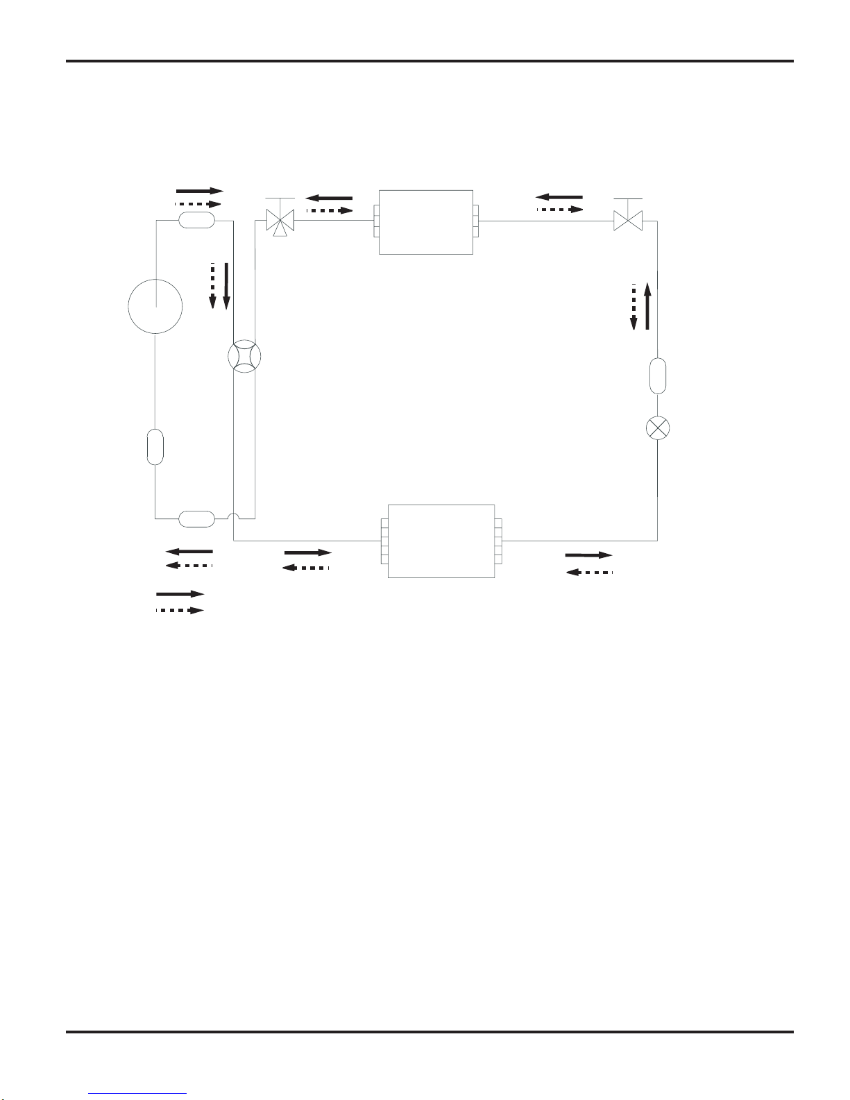
4. Refrigerant System Diagram
Refrigerant pipe diameter
Liquid :1/4" (6 mm)
Gas : 1/2" (12mm)
2-Way
valve
Strainer
Strainer
3-Way
valve
Muffler
4-Way valve
Capillary
Heat exchanger
( INDOOR )
Heat exchanger
( OUTDOOR )
rotalumucca-buS
rosserpmoC
Cooling
Heating
Schematic Diagram
13
5.1 Electrical Data
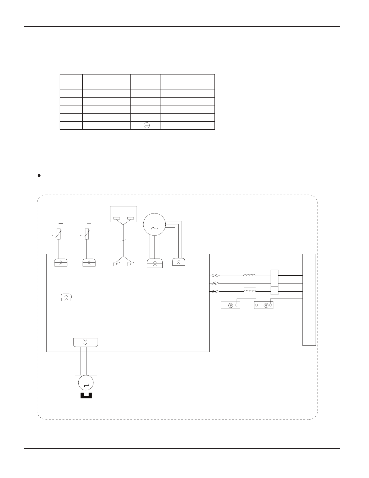
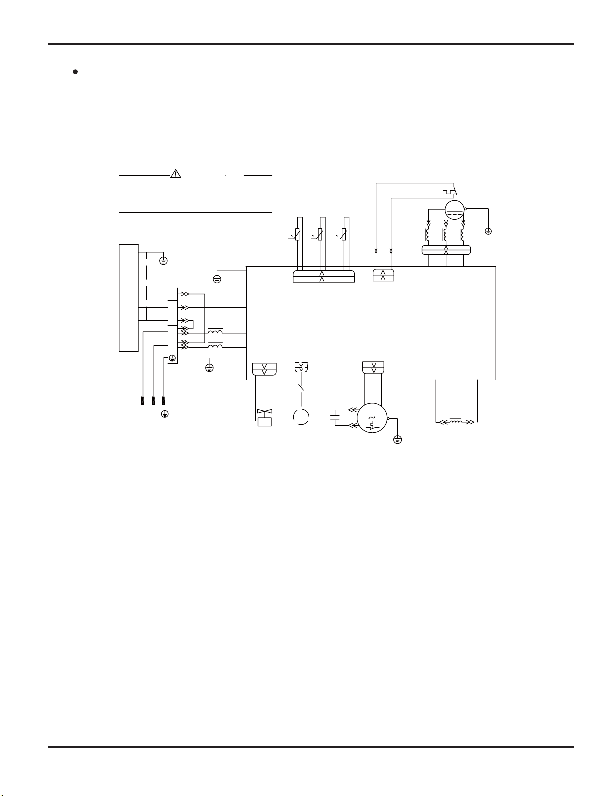
5.2 Electrical Wiring
Indoor unit
5. Schematic Diagram
Symbol Color symbol Symbol Color symbol
Symbol Parts name
BU BLUE
BN BROWN
YE YELLOW
BK BLACK
WHITE
RD RED
YEGN WHYELLOW GREEN
VT VIOLET
PROTECTIVE EARTH
OG ORANGE
RT1
PRINTED CIRCUIT BOARD
EARTHING PANEL
EVAPORATOR
YEGN
BN
BK
BU
OUTDOOR UNIT
M2
ROOM
TUBE
AP1
RT2
BK
BN
3
XT
2
N(1)
BU
YEGN
0
AP2
PEPE
M1
CAP
JUMP
DISP2
PGF
PG
TEM.SENSOR
TUBE ROOM
TEM.SENSOR
MOTOR
SWING
0
AC-L
N
COM-OUT
DISP1
DISPLAY
SWING-UD
Schematic Diagram
14
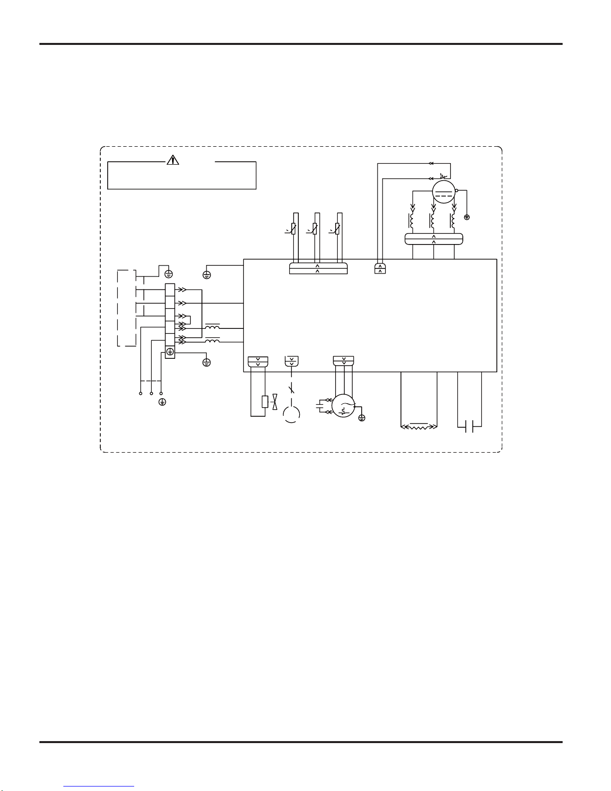
Outdoor unit
INDOOR UNIT
PE
BU
BN
N
L
PE
PE
N(1)
2
3
XT1
BK
BN
BU
YEG N
T- SENSOR
6YEGN
AC-L
N
PE
COMP-W COMP-V COMP-U
YE
BU
RD
U
V
W
PE
PE
COM-INNER
0
RT 1
0
RT 2
RT 3
0
4V
M1
L
INDC1
3RD
WH
PE
OF AN
OVC-COMP
5W H
4W H
SA T
OG
INDC2
COMP
4Y V
X1
CAP .
RD
BN
COMP .
2YE
1BU
WH
BK
TEM.SENSO R
OUTTUBE
OUTROO M
TEM.SENSO R
EXHAUST
TEM.SENSO R
YEG N
PE
FA N MO TO R
TERMINAL
BLOC K
4- WA Y VA LV E
C1
AP1
BU
BK
BN
YEG N
BN
BU
YEG N
EKV
FA
(OPTIONAL)
YEG N
N
L
POWE R
WA RNING
Please don't touch any terminal when the aircondition is
running or during the 15 minutes after the aircondition
stops to prevent the risk of electrical shock!
C1VO-18
Schematic Diagram
15
T-SENSOR
6YEGN
AC-L
N
14YEGN
10BU
PE
9BN
11BK
AP1
XT
3
2
N(1)
COMP-U
16BU
15YE
17RD
U
V
W
E
PE
PE
COM-INNER
0
RT1
0
RT2
RT3
0
4V
L
INDC1
1YE
2BU 3RD
12WH
OVC-COMP
5WH
4WH
SAT
13OG
INDC2
COMP
TEM.SENSOR
EXHAUST
TEM.SENSOR
OUTROOM
TEM.SENSOR
OUTTUBE
INDOOR UNIT
FA
EKV
PE
L
N
8BN
7BU
PE
PFCC2
19YE
18YE
PFCC1
C2
X1
20YEGN
COMP-V COMP-W
BU
BK
BN
YEGN
BN
BU
YEGN
(optional)
YEGN
C
RD
BN
FAN MOTOR
OFAN
PE
4YV
POWER
WARNING
Please don't touch any terminal when the voltage of
terminal P(DC+) and N(DC-) at AP1 is higher than 30V
to prevent the risk of electrical shock!
L
N
M
C1VO-24
Schematic Diagram
16
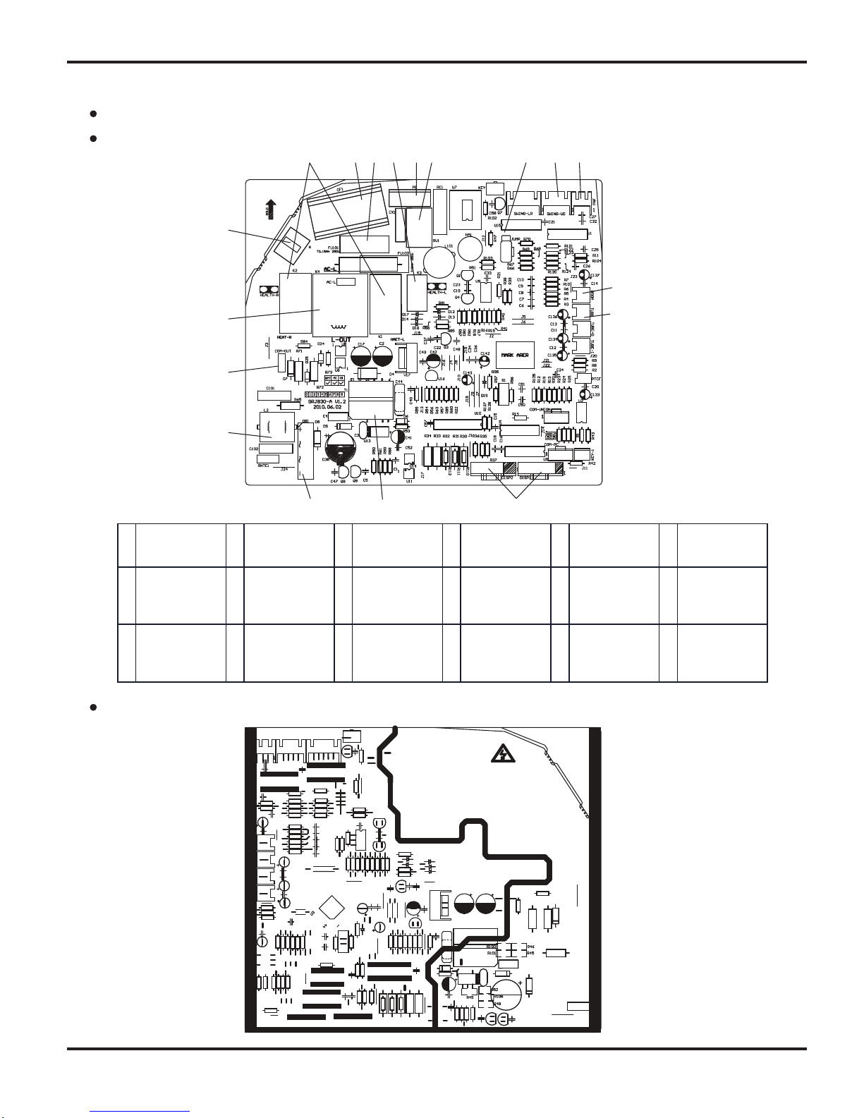
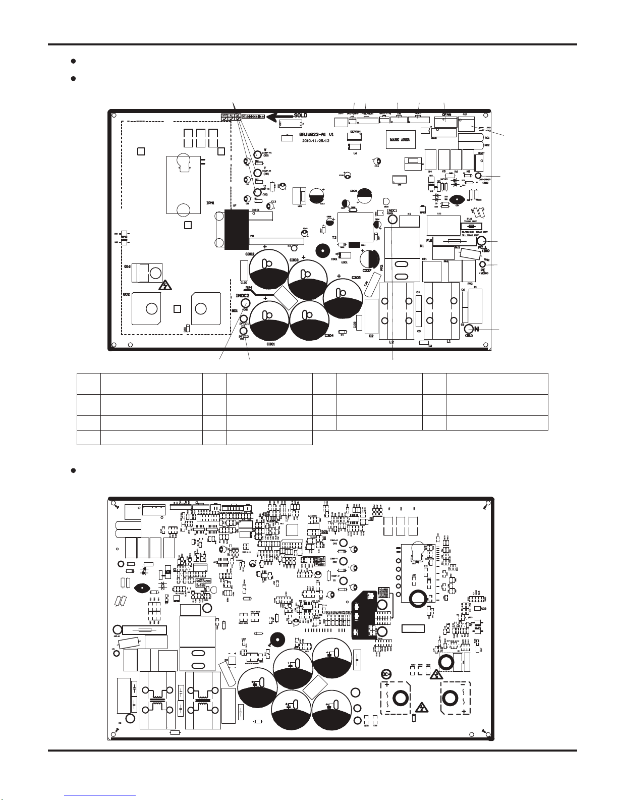
5.3 Printed Circuit Board
TOP VIEW
BOTTOM VIEW
Indoor unit
1
Copper pin
terminal of
neutral wire
2
Auxiliary heating
relay K1, K2
3 Fan capacitor 4 Protective tube 5 Health relay K3 6 PG motor terminal
7 Piezoresistor 8 Jumper cap 9
Up&down swing
terminal
10
PG feedback
terminal
11
Terminal of
ambient
temperature
sensor
12
Terminal of tube
temperature
sensor
13
Connect display
board
DISP1,DISP2
terminals
14
High-frequency
transformer T1
15 Rectifier DB1 16
Strainer
SF2022A-05220
17
Connect copper
terminal of
communication
line for indoor fan
1
8
Supply power for
control relay K4
of outdoor fan
1
2 3 4 5 6 7 8 9
10
11
12
13
1415
16
17
18
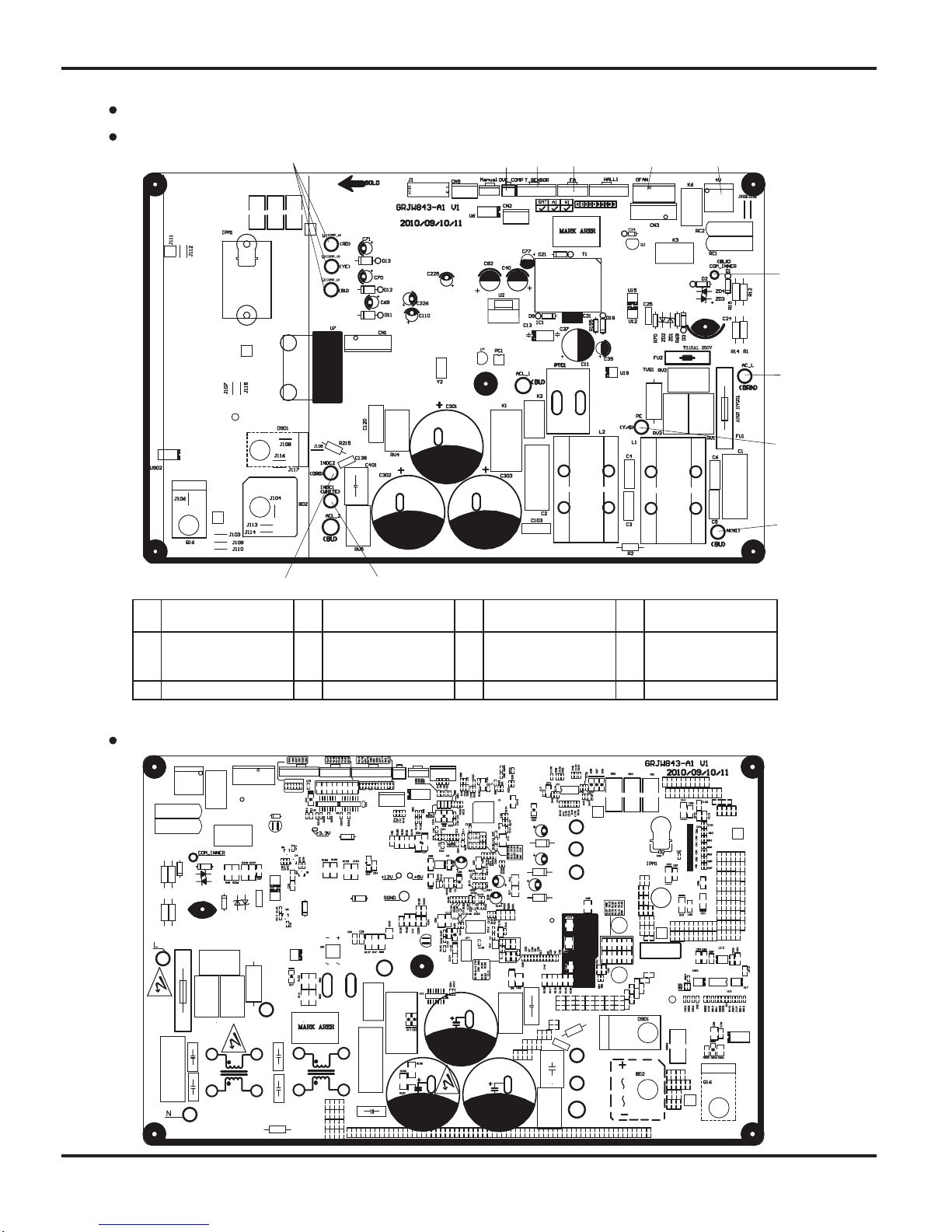
Schematic Diagram
17
TOP VIEW
BOTTOM VIEW
Outdoor unit(18k)
1
2 3 4
5
6
7
8
9
10
11
12
1 Compressor interface 2
Compressor
overloadprotector
3 Temperature sensor 4
Electric expansion
valve
5
Outdoor fan 6 4-way
valve
6 4-way valve 7
Communication
interface with indoor
unit
8 Live wire
9 Neutral wire 10 Earthing wire 11 Reactor interface 12 Reactor interface 2
Schematic Diagram
18
1
2 3 4 5 6
7
8
9
10
11
13 2141
1 Compressor interface 2
Compressor overload
protector
3 Temperature sensor 4 Electric expansion valve
5 Fan HALL interface 6 Outdoor fan 7 4-way valve 8
Communication interface
with indoor unit
9 Live wire 10 Earthing wire 11 Neutral wire 12 Reactor interface 1
13 PFC capacitor interface 1 14 Reactor interface 2
TOP VIEW
BOTTOM VIEW
Outdoor unit(24k)
Function and Control
19
6. Function and Control
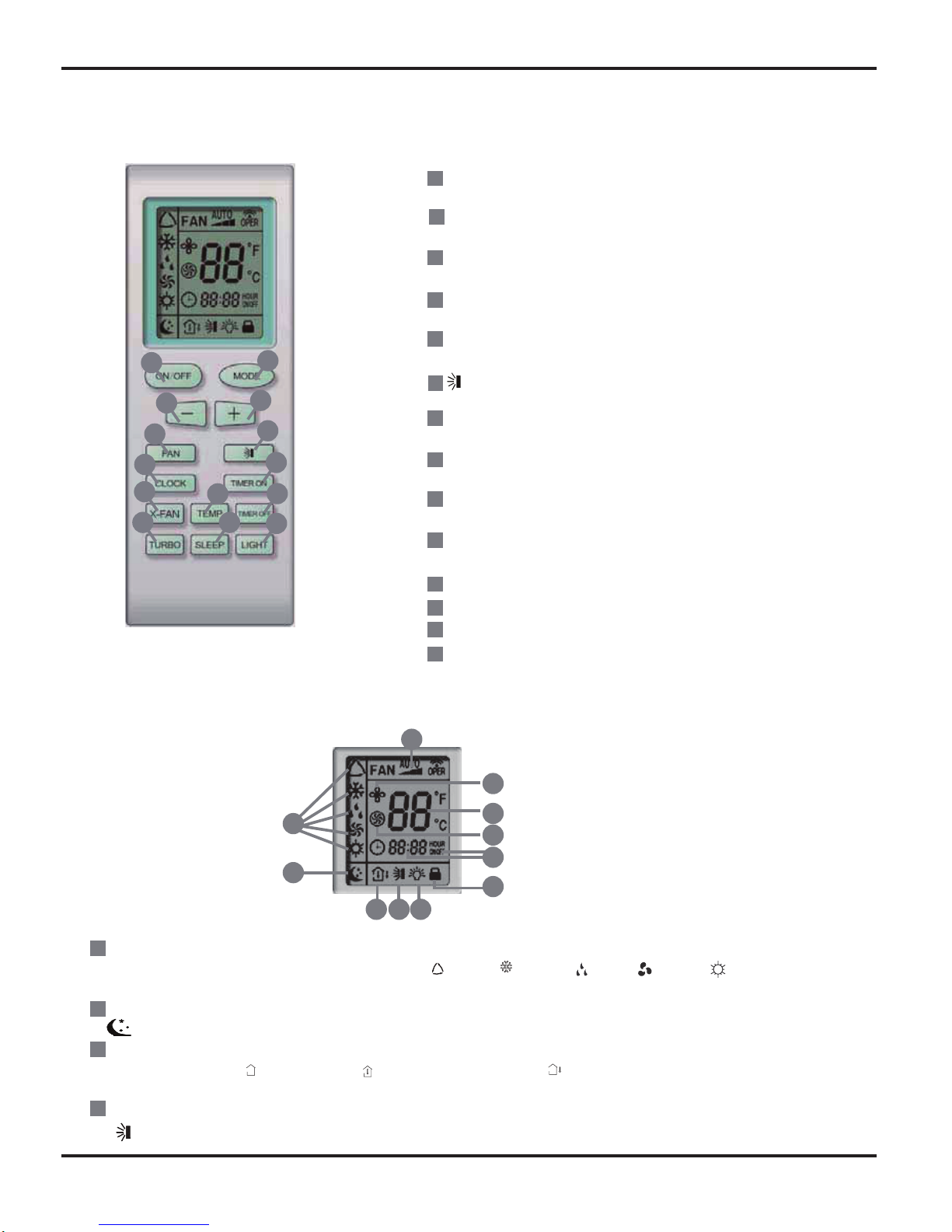
6.1 Remote Control Operations
1
7
8
4
3
5
6
11
13
12
16
17
18
10
14
9
15
2
2
8
9
10
3
4
11
12
7
6
13
14
5
1
ON/OFF
Press it to start or stop operation.
MODE
Press it to select operation mode (AUTO/COOL/DRY/FAN/HEAT).
+
Press it to increase temperature setting.
-
Press it to decrease temperature setting.
FAN
Press it to set fan speed.
Press it to set swing angle.
TIMER ON
Press it to set auto-on timer.
TIMER OFF
Press it to set auto-off timer.
CLOCK
Press it to set clock.
(X-FAN is the alternative expression of BLOW for the
purpose of understanding.)
X-FAN
TEMP
TURBO
SLEEP
LIGHT
Press it to turn on/off the light.
171518 19
16
20
21
23
24
22
25
MODE icon:
If MODE button is pressed, current operation mode icon (AUTO), ( COOL), (DRY), (FAN) or (HEAT is only for heat
pump models) will show.
SLEEP icon :
is displayed by pressing the SLEEP button. Press this button again to clear the display.
TEMP icon:
Pressing TEMP button, (set temperature), (indoor ambient temperature), (outdoor ambient temperature) and blank is
displayed circularly.
Up & down swing icon:
is displayed when pressing the up & down swing button. Press this button again to clear the display.
Function and Control
20
20
21
22
23
24
25
1
2
3
4
5
6
19
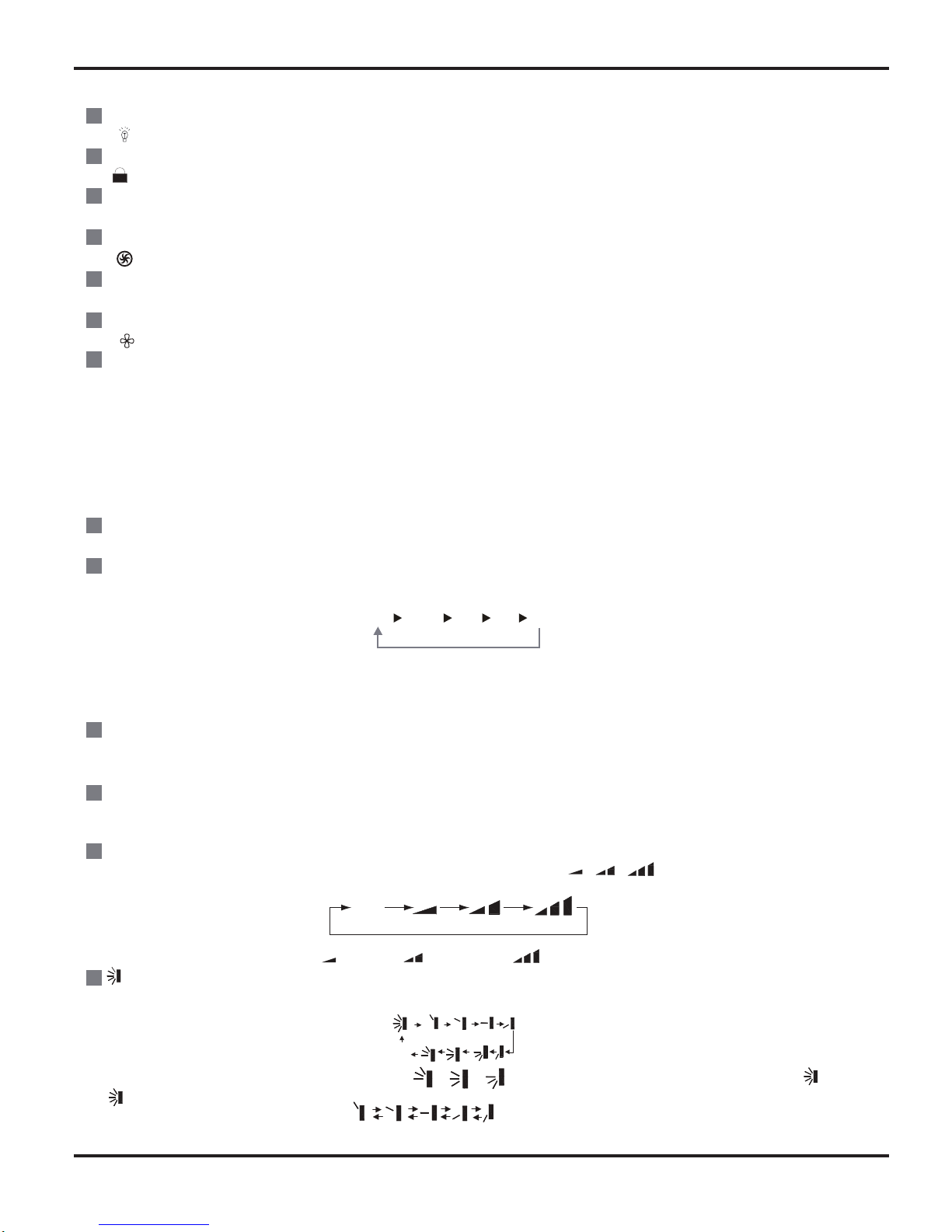
LIGHT icon:
is displayed by pressing the LIGHT button.Press LIGHT button again to clear the display.
LOCK icon:
is displayed by pressing "+" and “-” buttons simultaneously.Press them again to clear the display.
SET TIME display:
After pressing TIMER button, ON or OFF will blink.This area will show the set time.
TURBO icon:
is displayed when pressing theTURBO button.Press this button again to clear the display.
DIGITAL display:
This area will show the set temperature. In SAVE mode,"SE" will be displayed. During defrosting operation, “H1” will be displayed.
X-FAN icon:
is displayed when pressing the X-FAN button. Press this button again to clear the display.
FAN SPEED display:
Press FAN button to select the desired fan speed setting(AUTO Low-Med-High).Your selection will be displayed in the LCD windows,
except the AUTO fan speed.
ON/OFF:
Press this button to turn on the unit. Press this button again to turn off the unit.
MODE:
Each time you press this button,a mode is selected in a sequence that goes from AUTO, COOL,DRY, FAN, and HEAT *, as the
following:
*Note: Only for models with heating function.
After energization, AUTO mode is defaulted. In AUTO mode, the set temperature will not be displayed on the LCD, and the unit will
automatically select the suitable operation mode in accordance with the room temperature to make indoor room comfortable.
+ :
Press this button to increase set temperature. Hold it down for above 2 seconds to rapidly increase set temperature. In AUTO mode,
set temperature is not adjustable.
-:
Press this button to decrease set temperature. Hold it down for above . 2 seconds to rapidly decrease set temperature. In AUTO
mode, set temperature is not adjustable.
FAN :
This button is used for setting fan speed in the sequence that goes from AUTO, , , to then back to Auto.
Press this button to set up & down swing angle, which circularly changes as below:
This remote controller is universal. If any command , or is sent out, the unit will carry out the command as
indicates the guide louver swings as:
AUTO
COOL DRY FAN HEAT*AUTO
Low speed Medium speed High speed
OFF
Remote Controller Description
Function and Control
21
8
9
10
11
12
13
14
15
16
7
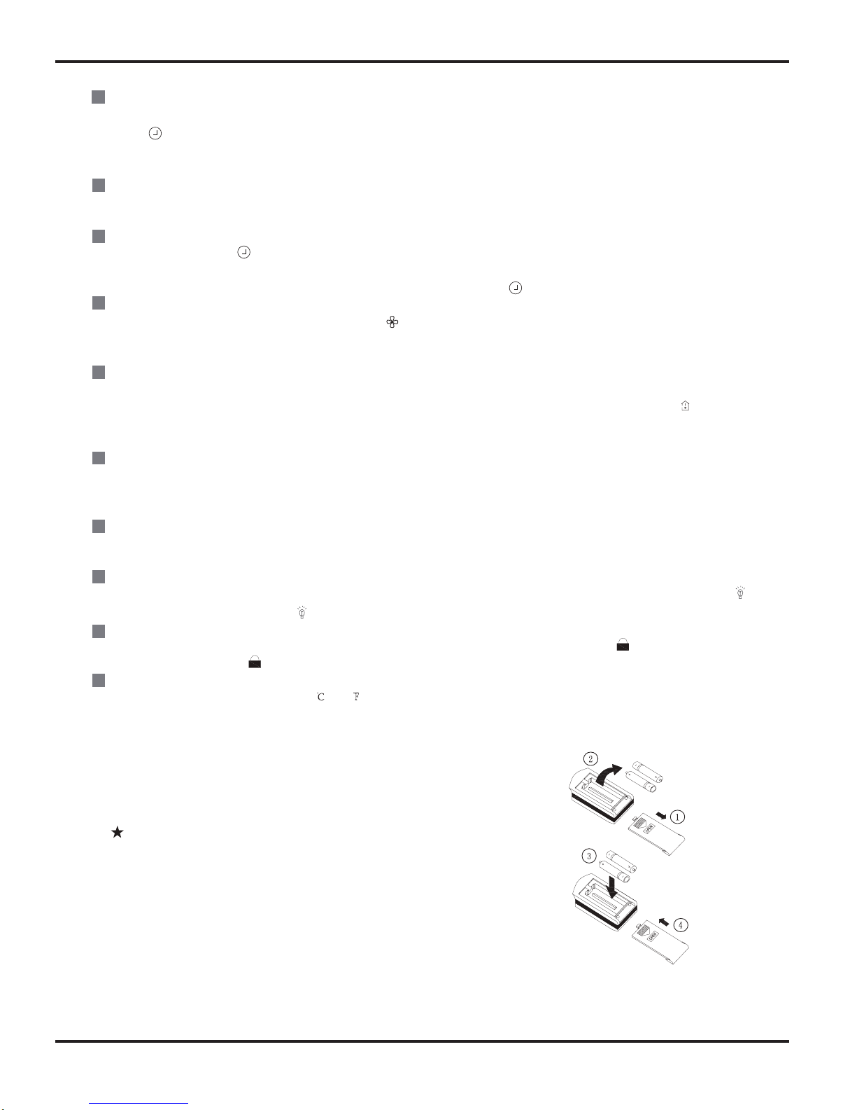
TIMER ON:
Press this button to initiate the auto-ON timer. To cancel the auto-timer program, simply press this button again. After pressing this
button, disappears and "ON" blinks . 0 0:00 is displayed for ON time setting. Within 5 seconds, press + or - button to adjust the
time value. Every press of either button changes the time setting by 1 minute. Holding down either button rapidly changes the time
setting by 1 minute and then 10 minutes. Within 5 seconds after setting, press TIMER ON button to confirm.
TIMER OFF:
Press this button to initiate the auto-off timer. To cancel the auto-timer program, simply press the button again.TIMER OFF setting is
the same as TIMER ON.
CLOCK :
Pressing CLOCK button, blinks. Within 5 seconds, pressing + or - button adjusts the present time. Holding down either button
above 2 seconds increases or decreases the time by 1 minute every 0.5 second and then by 10 minutes every 0.5 second. During
blinking after setting, press CLOCK button again to confirm the setting, and then will be constantly displayed.
X-FAN:
Pressing X -FAN button in COOL or DRY mode,the icon is displayed and the indoor fan will continue operation for 10 minutes in
order to dry the indoor unit even though you have turned off the unit.
After energization, X-FAN OFF is defaulted. X-FAN is not available in AUTO, FAN or HEAT mode.
TEMP:
Press this button, could select displaying the indoor setting temperature or indoor ambient temperature.When the indoor unit firstly
power on it will display the setting temperature, if the temperature's displaying status is changed from other status to" ",displays
the ambient temperature, 5s later or within 5s, it receives other remote control signal that will return to display the setting temperature. if the users haven't set up the temperature displaying status,that will display the setting temperature.
TURBO:
Press this button to activate / deactivate the Turbo function which enables the unit to reach the preset temperature in the shortest
time. In COOL mode, the unit will blow strong cooling air at super high fan speed. In HEAT mode, the unit will blow strong heating air
at super high fan speed.
SLEEP:
Press this button to go into the SLEEP operation mode. Press it again to cancel this function. This function is available in COOL,
HEAT (Only for models with heating function) or DRY mode to maintain the most comfortable temperature for you.
LIGHT:
Press LIGHT button to turn on the display's light and press this button again to turn off the display's light. If the light is turned on ,
is displayed. If the light is tunrned off, disappears.
Combination of "+" and "-" buttons: About lock
Press "+ " and "-" buttons simultaneously to lock or unlock the keypad. If the remote controller is locked, is displayed. In this
case, pressing any button, blinks three times.
Combination of "MODE" and "-" buttons:About switch between Fahrenheit and Centigrade At unit OFF, press "MODE" and "- "
buttons simultaneously to switch between
and .
Replacement of Batteries
1.Remove the battery cover plate from the rear of the remote controller.
(As shown in the figure)
2.Take out the old batteries.
3.Insert two new AAA1.5V dry batteries, and pay attention to the polarity.
4. Reinstall the battery cover plate.
Notes:
●When replacing the batteries, do not use old or different types of batteries.
Otherwise, it may cause malfunction.
●If the remote controller will not be used for a long time,
please remove batteries to prevent batteries from leaking.
●The operation should be performed in its receiving range.
●It should be kept 1m away from the TV set or stereo sound sets.
●If the remote controller does not operate normally, please take the
batteries out and reinsert them after 30 seconds. If it still can't operate
properly, replace the batteries.
Sketch map for
replacing batteries
Function and Control
22
6.2 Description of Each Control Operation
1.Basic function of system
(1)
Cooling mode
1.Under this mode, fan motor, swing will work under setting status, the temp. range is 16-30
(61-86 Fahrenheit
scale)
2.Outdoor unit malfunction or unit stop running, indoor unit will keep original running status, malfunction displayed.
3.When 0 (Tset-Tamb.), if indoor fan motor is high speed, that the fan motorist running in middle speed, the
middle speed or low speed will be maintained;(this condition should be executed when compressor start up);the super
high speed will not rotate; When (Tamb-Tset) , the fan will return to the setting fan speed.
(2)Dehumidifying mode
1.Under this mode, fan motor will run at low speed, swing will work at setting status, setting temp. range is 16-30
(61-86 Fahrenheit scale)
2.Outdoor unit malfunction or protection, unit will stop, indoor unit will keep original running status, malfunction
displayed.
(3)Fan mode
Under this mode, indoor fan motor could be setted at high speed, middle speed, low or auto speed, compressor,
outdoor unit and four-way valve will stop to run.
Under this mode, temp. range should be 16-30 (61-86 Fahrenheit scale)
(4)Heating mode
1.Under this mode, temp. range should be 16-30 (61-86 Fahrenheit scale)
2.Working condition
and procedure of heating mode: When unit turn on and enter into Heating mode, indoor unit
enter into anti-cool wind mode, when unit is stop running, and indoor fan motor turns on, blowing heat will act.
3.Protection function, under heating mode, compressor will stop to run due to malfunction happened, indoor fan
motor will blow surplus heat.
4.Defrosting control: When receiving the defrosting signal from outdoor unit, displayer will display H1, 10s later,
indoor fan motor will stop to run.
5.Anti-coold wind function
6.Blow heat air function
a.If heating temp. meets the compressor stop running condition, compressors, outdoor fan motor will stop to run,
the upper and lower guide louver will rotate to horizontal position L, indoor fan motor run at setting fan speed
for 60s, then the indoor fan motor will stop to run.
b.Dueto PG motor block running, the air guide board will keep the position when it
stopping. (under each mode),
other malfunction unit will stop to run, the upper and lower air guide louver will rotate to horizontal position
L, indoor fan unit will run at setting fan speed and run for 60s, indoor fan unit will stop to run.
(5)Auto mode:
1.When Tam
26 , select the cooling mode, at this time, the setting temp. is 25 .(77 Fahrenheit scale)
2.Cooling and heating units: Tamb 22
,will runat heating mode, at this time, the setting temp. is 20
3. Cooling only unit: When Tamb 22 , it will run at Fan mode, the setting temp. is 25 (77 Fahrenheit scale)
4.When 23 Tindoor amb. 25 ,firstly enter into auto mode and run at auto fan speed, other modes will
run at auto mode, will keep the previous running mode. (When entering into Dehumidifying mode, it will run at
auto fan speed)
(6)Auto fan speed control mode
(68Fahrenheit scale)
6.2.1 Functions of Indoor Unit
Function and Control
23
2. Display state of indoor indicators
(1) State of indoor display board
1. When the unit is powered on, all patterns will be displayed and then only power indicator is on. When the unit is turned on
with a remote controller, the operating indicator is on and operation mode which is set currently is displayed.
2. In defrosting mode, "H1" is displayed on "Double 8".
3. Set temperature is displayed on "Double 8".
Display of operation patterns and mode patterns
When the unit is powered on, all patterns will be displayed and the standby operation indicator will become red. When the unit
is turned on through a remote controller, the operation indicator is light. At the same time, operating mode patterns (mode
indicators include cooling, heating and dehumidification modes) set currently are displayed, and dynamic display patterns of
wind speed are displayed. If the light button is switched off, all display will be turned off.
Temperature display control mode of separated air conditioner
1. When user sets the remote controller at set temperature display, currently set temperature will be displayed.
2. Only when remote signals are converted from other display states into indoor ambient temperature display state, the
remote controller will display indoor ambient temperature for 5 seconds and then return to set temperature display.
3. Only when remote signals are converted from other display states into outdoor ambient temperature display state, the
remote controller
will display outdoor ambient temperature for 5 seconds and then return to set temperature display.
4. If the controller is lack of outdoor display functions, as the signal is received, set temperature will be displayed.
5. When the unit is turned off, temperature display will be compulsively set at given temperature by the controller. When the
unit is turned on, patterns as set by remote signals will be displayed.
6. If user does not set up temperature display state, given temperature will be displayed.
(2) Failure display of indoor unit
1. Requirements for failure display
When multiple failures appear at the same time, failure protection codes shall be displayed alternatively.
(1) Hardware failures shall be displayed immediately, referring to requirements in "Failure State Display Table";
(2) Operation states shall be displayed immediately, referring to requirements in "Failure State Display Table";
(3) Other failures shall be displayed 200s after the compressor stops, referring to requirements in "Failure State Display Table".
(Note: in
the case that the unit is switched off with the remote controller, or the compressor is switched on again, failure
display waiting time (200s) shall be cleared.)
(4) Frequency limitation and reduction states shall be displayed by means of remote calling.
3. Failure display control
Indicator failure display shall be kept synchronous with Double 8 failure display, that is, during indicator blinking, failure code
corresponding to such indicator shall be displayed on Double 8.
4. Method of remote calling of failure display
Entering the failure remote calling mode: push the light button four times within 3s to call out relevant failure protection code;
Quit the failure remote calling mode: push the light button four times within 3s or call out failure display to enter it for 5 minutes
and then quit.
3. Other control targets
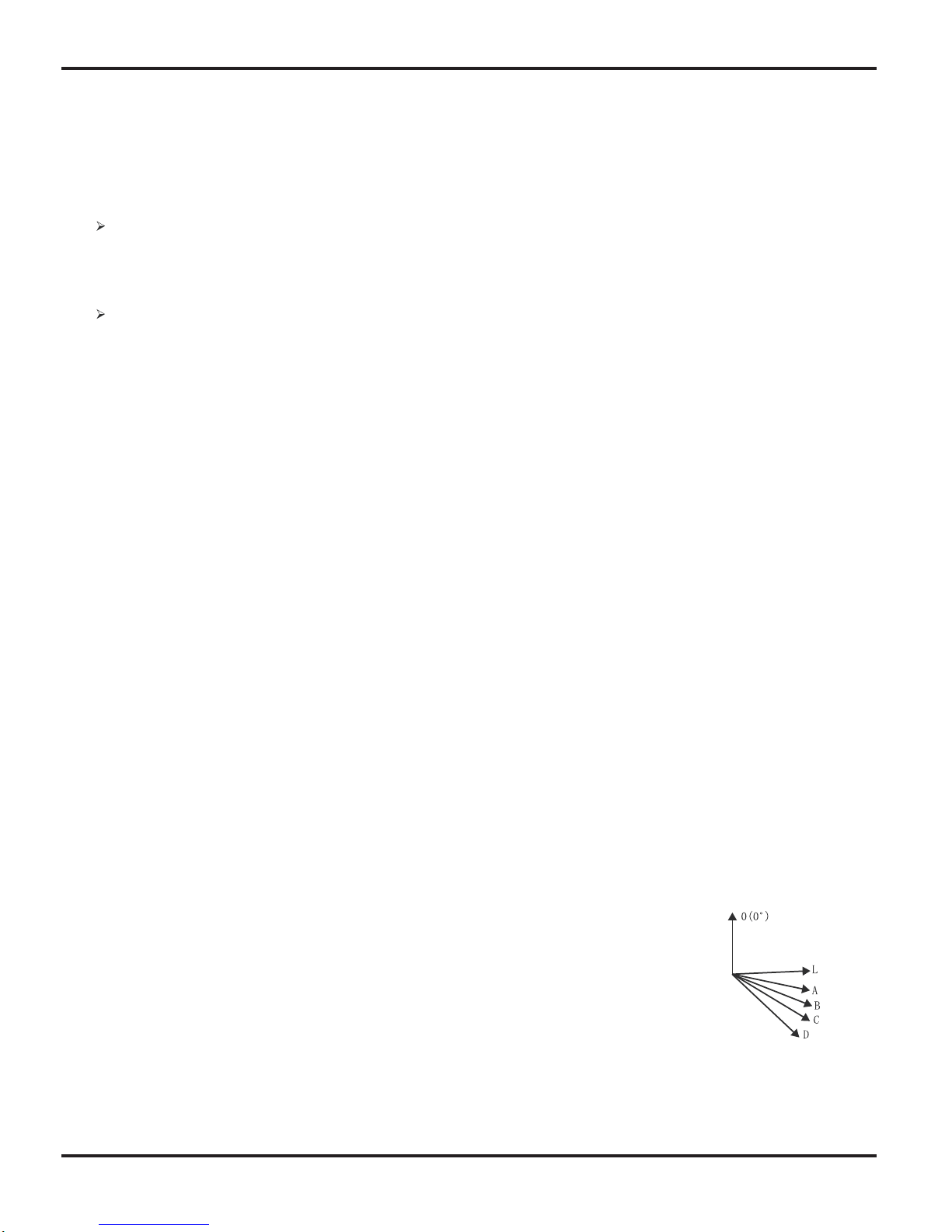
(1) Up and down wind blow functions: model of stepping motor is MP28EA.
When the unit is powered on, the up and down wind blow motor will turn a wind deflector anti-clockwise to Position 0 to shut
down the air outlet. When the unit is switched on and wind blow function is not preset, under the heating mode, up and down
wind blades will turn clockwise to position D; and under other modes, the up and down wind blades will turn clockwise to
position L. If wind blow function is set at the same time as the unit is switched on, the wind blades will swing between position
L and D. The wind blades can be kept in seven states: position L, position A, position B, position C, position D, swing between
position L and D, stop at one position from L to D. When the unit is turned off, the wind deflector will be closed up to position 0.
Wind blow action is effective only when wind blow commands are set and the indoor unit is running.
Note: When the wind blades are set at position L to B, position A to C, or position B to D through
remote setting,
the wind deflector will swing between position L and D. L—A—B—C—D.
(2) Buzzer
When the controller is powered on, signals from a remote controller are received, or the auto button
is pushed, a buzzer will give out prompt tone.
(3) Auto button
When the button is pushed, the unit will operate in auto mode and the indoor fan will run in auto state. When the indoor fan is
running, the wind blow motor will work. When the button is pushed again, the unit will be switched off. At the same time as the
button is pushed, the whole unit will be powered on and enter into fast test mode; when the unit is powered on and detects for
continuous 20s (such time shall not be fast tested) that the auto button is pushed, and if the unit is currently at fast test state,
the unit will quit the fast test state.
Function and Control
24
(4) Sleep function
This mode is effective only in cooling and heating modes. Proper sleep curves shall be selected for operation according to
preset temperature.
In cooling mode:
(1) When initial temperature is set at 16-23 , an increase of 1 will be gained every hour after the sleep function is activated.
After 3 is raised, the temperature will be maintained. After operation for 7 hours, temperature will go down by 1 ,
afterwards, the unit will operate at such temperature.
(2) When initial temperature is set at 24-27 , an increase of 1 will be gained every hour after the sleep function is activated.
A
fter 2 is raised, the temperature will be maintained. After operation for 7 hours, temperature will go down by 1 ,
afterwards, the unit will operate at such temperature.
(3) When initial temperature is set at 28-29 , an increase of 1 will be gained every hour after the sleep function is activated.
fter 1 is raised, the temperature will be maintained. After operation for 7 hours, temperature will go down by 1 ,
afterwards, the unit will operate at such temperature.
In heating mode:
(1) When initial temperature is set at 16 , the unit will operate at such temperature.
(2) When initial temperature is set at 17-20 , a decrease of 1 will be gained every hour after the sleep function is
activated. After 1 is reduced, the temperature will be maintained.
(3) When initial temperature is set at 21-27 , a decrease of 1 will be gained every hour after the sleep function is
activated. After 2 is reduced, the temperature will be maintained.
(4)
When initial temperature is set at 28-30 , a decrease of 1 will be gained every hour after the sleep function is
activated. After 3 is reduced, the temperature will be maintained.
(5) Timing function
The main board integrates general timing and moment timing. Such two timing functions can be selected through a remote
controller on which different functions are arranged.
1
General timing:
Timing start: timing start can be set when the unit is off. When preset time is reached, the controller will operate in a preset
mode. Timing can be set at an interval of 0.5 hour in a scope of 0.5 - 24 hours.
Timing stop: timing stop can be set when the unit is on. When preset time is reached, the system will be turned off. Timing
can be set at an interval of 0.5 hour in a scope of 0.5 - 24 hours.
2
Moment timing
Timing start: if timing start is set when the system is at operation state, the system will continue to operate; if timing start is set
when the system is at stop, as the preset time is reached, the system will start to run in preset mode.
Timing stop: if timing stop is set when the system is at stop state, the system will keep standby; if timing stop is set when the
system is in operation, as the preset time is reached, the system will stop running.
Timing change:
When the system is in timing mode, start and stop can be set through the On/Off button on the remote controller; or timing
time can be reset and the system will operate according to the latest setting.
When the system is in operation and both timing start and stop are set, the system will stay at currently set operation state.
When preset timing stop time is reached, the system will stop working.
When the
system is at stop state and both timing start and stop are set, the system will keep at stop state. When preset timing
start time is reached, the system will start operation.
From then on, the system will operate in preset mode at a preset start time and stop at a preset stop time everyday. If timing
stop time is set as the same as timing start time, a stop command will be executed.
(6) Dry and mildew proof function
Dry and mildew proof function can be set in cooling and dehumidification modes.
(7) Control of indoor fan
Indoor fan can be set at four levels, super-high, high, middle and low, with a remote controller. When one level is set, the fan
will thus operate at such level. The fan can also be set at auto state.
(8) Power off Memory Function
What will be memorized includes modes, up and down wind blow, light, preset temperature, preset wind speed, general timing
(no memory for moment timing), and Fahrenheit /Celsius degree. When the unit is powered on again after power failure,
operation continues according to memorized content. If timing is not set by the last remote control command, the system will
memorize the last remote control command and operate in the mode specified in the last remote control command. If timing is
set by the last remote control command and power failure happens before the preset time, the system, as powered on again,
will memorize the timing function set by the last remote control command. Timing will be re-counted from the time at which the
system is powered again. If timing is set by the last remote control command and timing of start or stop is reached before
power failure, the system, as powered on again, will memorize operation state before power failure and will not perform timing
action. Moment timing is out the range of memor
y.

Function and Control
25
(9) Locked Protection of PG Motor
When starting up the fans, if the motor has run at a lower speed continuously for a period, for preventing
automatic protection of the motor, stop running, and display the locked operation; if the machine is running at
present, the code of the locked fault---H6 of double-eight digital tubes will be displayed; if the machine is shut
down at present, the information of the locked fault will not be displayed.
(10) Super Power Function
In cooling and heating modes (automatic, dehumidifying and air-supplying modes are without strong power),
press the button of Super Power, the wind speed on the remote controller is displayed as super-high air flow, and
the inner fans are also turned to super-high air flow;
(11) Health Function
When the inner fans are running, the remote controller is set at the Health function at this time (if there is no
Health button on the remote controller, the Health On order is defaulted), then start the Health function device.
5. Fault Detection of Temperature Sensor
(1) Indoor Environment Temperature Sensor:
Detect the fault of thermo-bulb at any time;
(2) Indoor Pipe Temperature Temperature Sensor:
During the defrosting period, the fault of the thermo-bulb will be not detected, which shall be detected in 5
minutes after defrosting is completed; the fault of the thermo-bulb will be detected at other times;
(3) Protecting Treatments of Temperature Sensor:
1.When
the thermo-bulb is detected to be short-circuited continuously for 30 seconds:
It is
regarded that the temperature detected by the thermo-bulb is over-high (or unlimited), then the whole
machine will exert corresponding safety stops according to the over-high temperature sensed by the thermo-bulb,
and display corresponding temperature safety stops and faults of the thermo-bulb simultaneously.
2. When the thermo-bulb is detected in open circuit continuously for 30 seconds: stop the machine in protection,
directly display corresponding faults of the thermo-bulb.
6. Forced Running Function of the Inner Units
(1) Enter into Forced Running Control
Within 5 minutes after power-up, press the Lights Off button on the remote controller continuously for three
times within 3 seconds to enter into the fluorine collecting mode, and display Fo, send the fluorine-collecting
mode for 25 minutes continuously, each load will be treated as cooling when starting the machine (set the air flow
as High, set the temperature as 16
).
(2) Exit from the Forced Running Control
After receiving any remote signal, or signal of keys, the fluorine-collecting mode will exit, and operate in
accordance with the current orders set; or exit the fluorine-collecting mode after running for 25 minutes, and the
machine will be shut down automatically.
(It is refrigerants reclaiming function which is used for the condition that refrigerants cannot be reclaimed by
cooling operation in the season with low temperature.)
Function and Control
26
1. Input Parameter Compensation
(1) Input parameter compensation function
A
s the structure feature of split unit, concerning the comfort, in heating mode, when compressor stops, the indoor ambient
temperature is higher than preset temperature for 3 .
2. Check parameters to effectively make judgment and control
Insert the outdoor discharge temp sensor into corresponding temp sensor jacket of discharge pipe in order to protect safe and
reliable operation of the unit, so that the control system can accurately detect the discharge temp as well as effectively control
and protect it. Otherwise, the unit will stop and display the trouble of “outdoor discharge temp sensor failure ( not be inserted
correctly)” which can be recovered by pressing ON/OFF button.
3. Cooling Mode
3.1 Conditions and processes of cooling operation:
3.1.1 If the compressor stops, and [Tpreset – (Tindoor ambient – ΔTcooling indoor ambient temperature compensation)] ≤0.5 ,
start up the unit for cooling operation;
3.1.2 During cooling operation, if 0
≤ [Tpreset – (Tindoor ambient –ΔTcooling indoor ambient temperature compensation)]< 2 ,
keep the cooling operation;
3.1.3 During cooling operation, if 2
≤ [Tpreset – (Tindoor ambient –ΔTcooling indoor ambient temperature compensation)], the
cooling operation will stop after reaching to the setting temperature.
3.2 Temperature setting range
3.2.1 If Toutdoor ambient ≥ [Tlow-temperature cooling], the temperature can be set at: 16~30
(Cooling at roomemperature);
3.2.2 If Toutdoor ambient < [Tlow-temperature cooling], the temperature can be set at: 25~30
(Cooling at low temperature),
that is, the minimum setting temperature to be judged by outdoor unit is 25
.
4. Dry Mode
4.1 Conditions and processes of dry operation: same as the cooling mode;
4.2 The temperature setting range is: 16~30
;
5. Fan Mode
5.1 The compressor, outdoor fan and four-way valve are switched off;
5.2 The temperature setting range is: 16~30
.
6. Heating Mode
6.1. Conditions and processes of heating operation: (Tindoor ambient is the actual detection temperature of indoor
environment temp sensor, ΔTheating indoor ambient temperature compensation is the indoor ambient temperature compensation
during heating operation)
6.1.1 If the compressor stops, and [(Tindoor ambient –ΔTheating indoor ambient temperature compensation) –Tpreset]≤ 0.5
,
start the unit to enter into heating operation;
6.1.2 During heating operation, if 0
≤ [(Tindoor ambient –ΔTheating indoor ambient temperature compensation)–Tpreset] < 2 ,
keep the heating operation;
6.1.3 During heating operation, if 2
≤ [(Tindoor ambient –ΔTheating indoor ambient temperature compensation)–Tpreset], the
heating operation will stop after reaching the setting temperature.
6.2 The temperature setting range in this mode is: 16~30
.
7. Defrosting Control (heating)
7.1 After the time for defrosting is judged to be satisfied, if the temperature for defrosting is satisfied for continuous 3minutes, the
defrosting operation will start.
7.2 Start defrosting: Compressor stops and starts up 55S later;
7.3 Finish of Defrosting: Compressor stops and starts up 55S later;
7.4 The defrosting operation can exit when any of the conditions below is satisfied:
7.4.1 Toutdoor pipe≥ 12
;
7.4.2 Toutdoor ambient
-5 , and the Toutdoor pipe≥ 6 last more than 80S;
7.4.3The continuous running time of defrosting reaches.
8. Compressor Control
8.1. The frequency of compressor will be controlled according to the relationship of ambient temperature and preset temperature
as well as changing speed of ambient temperature;
8.2 Start the compressor after starting cooling, heating, dry operation, and the outdoor fan for 5s;
8.3 When the unit is off, in safety stops and switching to fan mode, the compressor will stop immediately;
8.4 In all modes: once the compressor starts up, it will not be allowed to stop within 7 min. (Note: except the cases that require
stop of the compressor such as fault protection, remote shutdown, mode switching etc.);
6.2.2 Functions of Outdoor Unit
 Loading...