

inVENTer Pulsar Installation And Operating Instructions Manual
Pulsar extractor fan
Installation and operating instructions

Trademarks, copyrights and property rights
inVEN Ter® is a registered trademark of inVENTer GmbH.
The copyright of this document remains with the manufacturer.
Rights to all content s and images: © inVENTer GmbH 2016-17.
All trademarks used in this document are the propert y of their respective
manufacturers and are hereby acknowledged.
Disclaimer
This documentation is an translation of the original German installation and
operating instruc tions. Af ter completion of the installation it must be given
to user (tenant, owner, property management, etc.). The content of this
documentation has been checked for compliance with the described hardware
and software. Nevertheless deviations may still o ccur, therefore no guarantee
of compliance can be provided. This documentation des cribes the functionality
of the standard scope. The documentation does not purport to cover all details
on all types of the product and cannot cover every conceivable scenario for
installation, assembly, operation, cleaning and maintenance. The illustrations in
this document may differ slightly from the design of the product that you have
purchased. The same functionality is ensured despite any design deviations.
This doc umentation is up dated regularly. N ecessary co rrections and a ppropriate
suppleme nts are always included in subsequent editions. You can fin d the latest
version at www.inventer.eu/downloads
Version 1.3
2

Table of contents
TABLE OF CONTENTS
User and safety instructions
1.1 User instructions ...................................................4
1.2 Safety instructions .................................................4
2 System overview .........................................................6
2.1 Functions ..............................................................7
3 Preparing for installation ............................................8
3.1 Installation conditions ............................................8
3.2 Dimensions ...........................................................9
3.3 Dimensional drawing .............................................9
4 Elektrical connections ................................................10
4.1 Electrical connection 100 – 240 V AC...................10
4.2 Electrical connection 12 V DC ..............................14
5 Installation ...................................................................16
5.1 Creating the wall opening and
installing the wall sleeve ......................................16
5.2 Installing the PSU (optional) ..................................18
5.3 Inserting and connecting the
Pulsar extractor fan .............................................20
5.2 Installing the fan casing’s cover and fan unit .........25
6 Commissioning ............................................................27
7 Operation .....................................................................28
7.1 Functional scope .................................................28
7.2 Status LED ..........................................................29
8 Cleaning and maintenance .........................................30
9 Specications ..............................................................32
10 Delivery .......................................................................33
11 Accessories ................................................................33
12 Warranty and service ................................................34
Company details .......................................................35
PIN code/serial number ............................................36
3
USER AND SAFETY INSTRUCTIONS
1 User and safety instructions
Thank you for purchasing this high quality product from inVENTer! This section provides an overview of the basic safety
precautions for safe and proper operation of your ventilation unit.
1.1 User information
Concept of safety instructions
The safety and warning instructions in these instructions
have a uniform structure and are marked with a symbol on
the left side of the instruction. The colour of the symbol
indicates the hazard level. A signal word above the text also
indicates the hazard level. If several hazard levels exist, the
highest level safety instruction is always used.
SIGNAL WORD
Type and origin of the hazard.
Possible consequences of the hazard!
►Measures to avoid the hazard.
A signal word indicates the severity of the potential hazard
unless the preventative measures are taken.
Danger indicates: Direct danger of serious injury
or death.
CAUTION indicates: Imminent or possible risk of
minor/significant injury.
NOTICE indicates: Imminent or possible damage to
property due to an adverse event/state.
Other symbols used in this documentation
A TIP symbol indicates practical and useful tips for
handling your extractor fan.
A tool symbol before an installation sequence lists
the necessary tools for the described work.
► Action required: This requires you to perform a
specific action.
Check the results: This requires you to check the
results of the action you have performed.
The illsustrations always show the interior wall.
1.2 Safety instructions
These installation and operating instructions are
part of the ventilation unit and must be permanently
available. When handing the equipment/system to a third
party, the installation and operating instructions must
be handed over also. Before performing any work on the
system, read the installation and operating instructions
carefully and observe all information regarding installation,
commissioning and maintenance contained in this section.
Also note the safety instructions that precede the described
handling instructions.
Non-observance of safety warnings could result in injury
and/or property damage.
4
Pulsar extractor fan • Installation and operating instructions

USER AND SAFETY INSTRUCTIONS
Intended use
The Pulsar extractor fan is designed to ventilate rooms
with external windows, taking into account the specifications and applications described in these instructions, and
only in conjunction with components that are recommended by inVENTer GmbH and mentioned in this documentation. Changes or modifications to the equipment/system
are not permitted.
Trouble-free and safe operation of the equipment depends
on proper transportation, proper storage and installation
as well as careful operation and maintenance. Observe
all safety instructions that are contained in this documentation.Any kind of use other than the intended use will
exclude all liability claims.
Improper use
Do not install the equipment in areas which...
• contain (or may contain) strong oils or lubricants.
• contain (or may contain) flammable gases, liquids or
vapours.
• are exposed to ambient temperatures below 5 °C and
above 50 °C
• contain (or may contain) obstacles preventing access to
the fan or its removal.
Qualified personnel
The equipment may only be set up and operated in conjunction with this documentation. Installation and operation
may only be carried out in conjunction with this documentation. Installation and electrical connection of the
equipment may only be performed by qualified personnel.
Qualified personnel within the meaning of the safety notices
in this documentation are persons who are authorised to
install, put it into operation and identify equipment, systems
and circuits in accordance with established safety procedures.
General safety regulations
• Always observe the relevant standards, regulations and
guidelines when working.
• The Pulsar extractor fan is designed for fixed installation
with permanent cabling.
• DANGER: Observe the installation instructions in accordance with VDE 0100 when establishing connections in
damp areas. The Pulsar extractor fan may only be installed
outside protection area 0 ( 3.1, page 8).The Pulsar
extractor fan must not be used in areas in which direct
contact with water spray is possible over a prolonged
period.
• DANGER: When laying the power supply cable, observe
the requirements of protection class II.
• DANGER: Ensure that the power supply (voltage,
frequency and phase) correspond to the specifications on
the type plate.
• CAUTION: Operation and/or maintenance of the device
must not be carried out by children and/or persons who
are not fully capable of doing so due to their physical,
sensory or mental capabilities, inexperience or lack of
knowledge. Young children should be supervised to ensure
that they do not play with the device.
• Ensure sufficient air supply in the room, for example, via a
large gap under the door.
• CAUTION: Install a pressure monitor in rooms with open
flues. Consult your chimney sweeper and/or building
planner!
• The extractor fan may only be commissioned after
completion of the construction project.
Pulsar extractor fan • Installation and operating instructions
5
SYSTEM OVERVIEW
2 System overview
The Pulsar is a n innovative extractor fa n with a contemporary
design.
It improves the basic ventilation in your rooms and enables
continuous ventilation to reduce humidity and odours in wet
rooms (WC/bath/shower room/laundry room). Furthermore,
the Pulsar can be used as a wall-vent fan.
The Pulsar can be used in conjunction with the aV100 wall
installation set or installed in another wall sleeve with a
diameter of 100 – 140 mm (in this case a back-draught
shutter must be retrofitted on site). Installation is possible
in ceilings and exterior walls. If the Pulsar extractor fan is
used as a wall-vent fan, it can also be installed in interior
walls. The Pulsar can be connected directly to the 230 V
mains or via a power supply unit. Note that not all functions
are available when connecting to 12 V DC.
In order to ensure that the device does not interfere with
other ventilation processes and that its functioning is not
affected by them, it must always be installed in its own
wall sleeve. This must not contain any obstructions or other
objects that interfere with the airflow.In order to prevent
the accumulation of condensate (in winter) in wall sleeves,
they must be insulated at the places where they run through
unheated areas, such as cold attics.
1
2
4
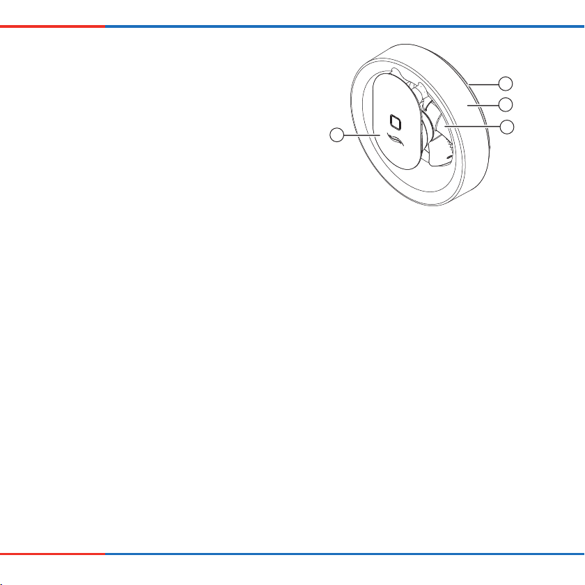
Figure 1: Pulsar extractor fan with cover
1 Rubber seal
2 Fan casing’s cover
3 Fan
4 Fan unit
3
Features
• Extractor fan with App control
• Can be installed in protection area 1 bath and shower
rooms in accordance with VDE 0100
• Wall or ceiling mounting possible
• 230 V connection (AC) or protective low voltage with
12 V connection (DC) possible
• Ultra-low-noise operation
• Control and set-up using the inVENTer Mobile app via
mobile device
• Humidity sensor with adjustable sensitivity
• Light sensor with adjustable sensitivity, run-on control
and delayed power-on
• Intelligent pause function, interval mode and boost mode
• Easy cleaning thanks to the easily accessible fan unit
6
Pulsar extractor fan • Installation and operating instructions

2.1 Function
SYSTEM OVERVIEW
The Pulsar extractor fan is programmed to suit most
installations.
The following factory settings are pre-programmed:
• Control by exposure to light: If the light conditions
change, i.e. lights are switched on, the shadows change,
or a person enters the room, the fan starts with a flow
rate of approx. 60 m³/h and runs for 15 minutes. Afterwards, the Pulsar extractor fan is switched off again.
• Control by humidity sensor: If the humidity increases
strongly, for example when the shower is used, the flow
rate rises to a maximum of 95 m³/h. When the humidity
decreases, the Pulsar extractor fan is switched off again.
When the extractor fan is switched on for the first time, the
factory settings are active.
Additional control and configuration of the Pulsar is possible
via the inVENTer Mobile app.
If required, the Pulsar extractor fan can also be used as a
wall-vent fan for ventilation and heating of adjacent areas,
e.g. unheated rooms. The extractor fan turns on when the
selected temperature limit is exceeded. It switches off again
when the room temperature falls back within the selected
range.
The extractor fan is controlled and configured using the
inVENTer Mobile app.
You can download the app for free from
the Google Play Store (Android) or
the App Store (iOS).
Technical requirements:
• Mobile device with Android or iOS operating system
• Bluetooth Smart
The following additional settings and functions can be
changed via the inVENTer Mobile app:
• Flow rate
• Sensitivity of the humidity sensor
• Sensitivity of the light sensor
• Run-on time
• Power-on delay
• Boost function
• Intelligent pause function
• Interval mode
• Settings for continuous ventilation
• Temperature settings when used as a wall-vent fan
You can find out more about
the possibilities offered by
inVENTer Mobile and download the app directly here:
www.inventer.de
Pulsar extractor fan • Installation and operating instructions
7
PREPARING FOR INSTALLATION
3 Preparing for installation
3.1 Installation conditions
Electrical protection areas according to VDE 0100
DANGER
Ingress of water into the Pulsar extractor fan
or its power source.
Electric shock and overheating due to short circuit
(230V, 50Hz)!
►Install Pulsar outside protection area 0.
►Install light switch/switch/pushbutton outside
protection areas 0 to 2.
1
Area 1
2
Figure 2: Overview of electrical protection areas in bathrooms
1 Pulsar extractor fan
2 External operating element (switch/pushbutton)
Area 0
Area 2
600
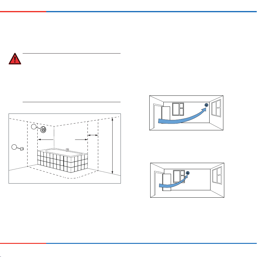
Positioning in the air flow of the room
Install the Pulsar extractor fan within the air flow of
the room. This will ensure optimal humidity extraction
and reliable detection of the humidity by the humidity
sensor.
Figure 3: Ideal positioning
2250
Figure 4: Non-ideal positioning
8
Pulsar extractor fan • Installation and operating instructions
60
21
PREPARING FOR INSTALLATION
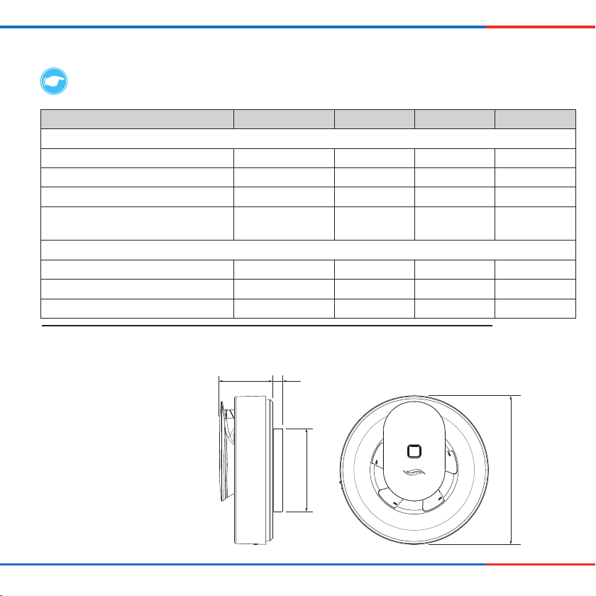
3.2 Dimensions
TIP: Ensure a minimum clearance of 250 mm to other components in front of and around the unit.
Designation Depth/length [mm] Width [mm] Height [mm] [ø, L in mm]
Wall opening:
Borehole for wall sleeve Wall thickness – – 115
Borehole for suspended ceiling Wall thickness – – 105
Borehole for flush-mounted box for PSU 66 – – 68
Borehole for flush-mounted plaster board
box for PSU
61 – – 68
Installation elements:
Pulsar extractor fan 81 – – 177
Wall sleeve DN 100 Wall thickness – – 100
Power supply unit (PSU) – – 32 54
1) Wall sleeves are available in the aV100 wall installation set including weather protection hood, from inVENTer GmbH.
2) A power supply unit is required for the 12 V DC connection. PSU and flush-mounted (plasterboard) box are available from inVENTer GmbH.
3.3 Dimension drawing
Ø99
Pulsar extractor fan • Installation and operating instructions
Ø177
9
ELECTRICAL CONNECTIONELECTRICAL CONNECTION
4 Electrical connection
The Pulsar extractor fan can be connected directly to the 230 V AC mains
or can be operated with 12 V DC (SELV). A power supply unit is available as an option.
NOTICE
Simultaneous connection of 230 V AC and 12 V DC.
Damage to the Pulsar extractor fan!
►Never simultaneously connect the Pulsar extractor fan to 230 V AC and 12 V DC.
4.1 Electrical connection AC 100 – 240 V (Alternating current)
DANGER
Exposed electrical components.
Electric shock and injury due to live components (230 V, 50 Hz)!
►Before working on electrical installations, disconnect all affected equipment from the power supply.
►Do not lay or connect live cables.
►The connection must only be performed by qualified and trained personnel.
DANGER
Ingress of water into the Pulsar extractor fan or its components/power source.
Electric shock and overheating due to short circuit (230V, 50Hz)!
►Install Pulsar outside protection area 0.
►Install Pulsar’s power source outside protection area 2.
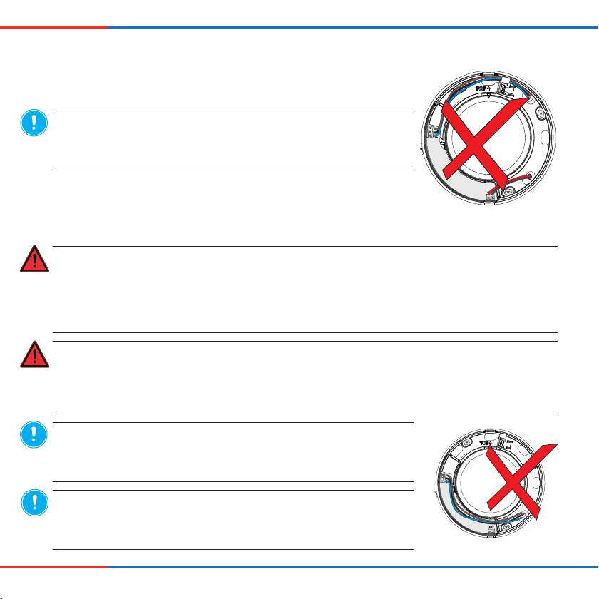
NOTICE
Insufficient wire cross-section.
Excessive voltage drop and/or contact cannot be guaranteed!
►For the power cable (mains cable) use a wire cross-section of 1.5 mm².
NOTICE
Power cable routed over PCB cover.
Damage to the PCB and no function of the Pulsar extractor fan!
►Do not route the 100 – 240 V AC power cable over the PCB.
10
Pulsar extractor fan • Installation and operating instructions
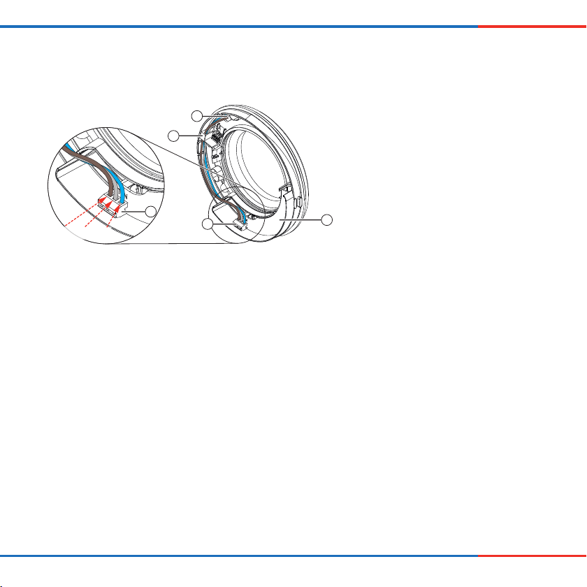
Terminal assignment for power cable
ELECTRICAL CONNECTIONELECTRICAL CONNECTION
1
2
1 Cable inlet for power cable
2 Cable feed-through on Casing
3 Connection terminal for power cable, 230 V
AC, 3-pole
4 PCB
3
Ls L N
Figure 5: PCB of Pulsar extractor fan: Terminal assignment for power cable connecting terminal (230 V AC)
3
4
Wiring diagrams for 230 V AC connection
The connection of the extractor fan depends on the desired functions.Ensure that you connect the extractor fan correctly
and select the correct presets for your desired functions during commissioning.
Pulsar extractor fan • Installation and operating instructions
11
 Loading...