

inVENTer GS62 Installation And Operating Instructions Manual
Installation and Operating Instructions 09/2013
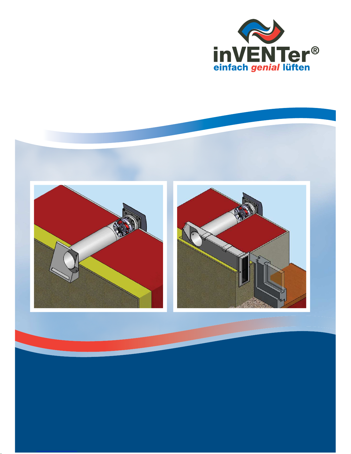
GS62 Air Extractor System
GS62 Air Extraction System • Installation and Operating Instructions 09/2013
2
LEGAL NOTICES
WARNING CONCEPT
These instructions contain information for your personal safety and to prevent material damage. Information for your
personal safety is denoted by a warning triangle. Information pertaining to material damage only has no warning
triangle. The warnings are grouped according to these levels of risk:
DANGER indicates that death or serious injury will result if proper precautions are not taken.
WARNING indicates that death or serious injury can result if proper precautions are not taken.
CAUTION with warning triangle denotes that minor injury can result if proper precautions are not
taken.
CAUTION
without warning triangle denotes that material damage can result if proper precautions
are not taken.
BEWARE denotes that an undesirable event or state can result if the relevant advisory is not heeded.
Should there be more than one level of risk, the warning for the highest level of risk is always used. A warning about
personal injury with a warning triangle may also include a warning about material damage.
NOTE denotes further, useful information.
QUALIFIED PERSONNEL
The unit/system may only be installed and operated in conjunction with this documentation. Installation, electrical
connection and initial startup of the unit/system may only be performed by qualified personnel. Qualified personnel
within the context of safety-related information in this documentation are those authorized to install, start up and
identify equipment, systems and electrical circuits in accordance with safety engineering standards.
INTENDED USE > WARNING
When installing the equipment/system, observe the applicable building codes, fire protection
regulations and accident prevention regulations of the Employer's Liability Insurance Association. Only
use the equipment/system as intended for the applications described in this documentation and only
in conjunction with the components recommended, approved and specified in this documentation
by Öko-Haustechnik inVENTer GmbH. Changes and modifications to the equipment/system are not
permitted. Trouble free and safe operation of the equipment/ system requires proper transportation,
proper storage and assembly, as well as careful operation and maintenance. This documentation is
part of the equipment/system and must be accessible at all times. Observe all safety regulations in
this documentation.
TRADEMARKS
inVENTer® is a registered trademark of ÖkoHaustechnik inVENTer GmbH. Other names used in this documentation
may be trademarks whose use by third parties may infringe upon the rights of the owner.
EXEMPTION FROM LIABILITY
The content of this documentation has been reviewed for compliance with the hardware and software described.
However, discrepancies cannot be ruled out and so liability cannot be assumed for full compliance. This
documentation is updated regularly. Necessary corrections and appropriate additions are always included in
subsequent versions.
As of: 07/2013

3
TABLE OF CONTENTS
1 System overview . . . . . . . . . . . . . . . . . . . . . . . . . . . . . . . . . . . . . . . . . . . . . . . . .5
2 Description . . . . . . . . . . . . . . . . . . . . . . . . . . . . . . . . . . . . . . . . . . . . . . . . . . . . . .7
2.1 Features ..................................................................................................................7
2.2 Assembly ................................................................................................................7
3 Operating conditions . . . . . . . . . . . . . . . . . . . . . . . . . . . . . . . . . . . . . . . . . . . . . .8
3.1 Telescopic tube .......................................................................................................8
3.2 Flat duct (GS62-Corner) .........................................................................................8
4 Functional elements / interfaces . . . . . . . . . . . . . . . . . . . . . . . . . . . . . . . . . . . . .9
4.1 GS61 PSU ..............................................................................................................9
5 Installation . . . . . . . . . . . . . . . . . . . . . . . . . . . . . . . . . . . . . . . . . . . . . . . . . . . . . . .9
5.1 Installation preparation ...........................................................................................9
5.2 PSU .......................................................................................................................10
5.3 Telescopic tube ....................................................................................................10
5.4 Fitting the telescopic tube into the wall ................................................................12
5.5 Protective hood.....................................................................................................13
5.6 Nonreturn valve .....................................................................................................14
5.7 Fan housing ..........................................................................................................14
5.8 Inner baffle ............................................................................................................16
5.9 Flat duct (GS62-Corner) .......................................................................................17
5.10 Dimensional drawings...........................................................................................18
5.10.1 GS62 with protective hood ...................................................................................18
5.10.2 GS62 with GS62-Corner .......................................................................................20
6 Electrical connection . . . . . . . . . . . . . . . . . . . . . . . . . . . . . . . . . . . . . . . . . . . . .22
7 Technical details . . . . . . . . . . . . . . . . . . . . . . . . . . . . . . . . . . . . . . . . . . . . . . . . .24
7.1 GS62 air extraction system ..................................................................................24
7.2 GS61 PSU ............................................................................................................25
7.3 Fan ........................................................................................................................25
7.4 Telescopic tube .....................................................................................................25
7.5 Inner baffle ............................................................................................................26
7.6 Protective hood.....................................................................................................26
7.7 Flat duct ................................................................................................................26
7.8 Grate with sleeve ..................................................................................................26
7.9 Fan housing ..........................................................................................................26
7.10 Nonreturn valve .....................................................................................................26
8 Deliverables, accessories and spare parts . . . . . . . . . . . . . . . . . . . . . . . . . . .27
8.1 Deliverables ..........................................................................................................27
8.2 Accessories ..........................................................................................................27
8.3 Spare parts ...........................................................................................................27

4
GS62 Air Extraction System • Installation and Operating Instructions 09/2013
TABLE OF CONTENTS
9 Maintenance and repair . . . . . . . . . . . . . . . . . . . . . . . . . . . . . . . . . . . . . . . . . . . . . . 28
10 Troubleshooting and disposal . . . . . . . . . . . . . . . . . . . . . . . . . . . . . . . . . . . . . . . . .29
10.1 Troubleshooting .......................................................................................................... 29
10.1.1 GS62 air extraction system ........................................................................................ 29
10.1.2 Functional modules .................................................................................................... 29
10.2 Disposal ...................................................................................................................... 29
11 Warranty and service . . . . . . . . . . . . . . . . . . . . . . . . . . . . . . . . . . . . . . . . . . . . . . . 30
11.1 Terms of warranty ....................................................................................................... 30
11.2 Service ........................................................................................................................ 30
Legal notice . . . . . . . . . . . . . . . . . . . . . . . . . . . . . . . . . . . . . . . . . . . . . . . . . . . . . . . 31
5
SYSTEM OVERVIEW
3
1 SYSTEM OVERVIEW
The GS62 was developed for the ventilation of rooms with outside windows in single and multiple occupancy
houses, hotels and guest houses. It is an air extraction system that works without heat recovery and with direct
current.
Application areas
The GS62 is fitted into the outside wall of a building and can be used for:
• Bathrooms / toilets
• Kitchens
• Utility rooms
• Hallways
Variants
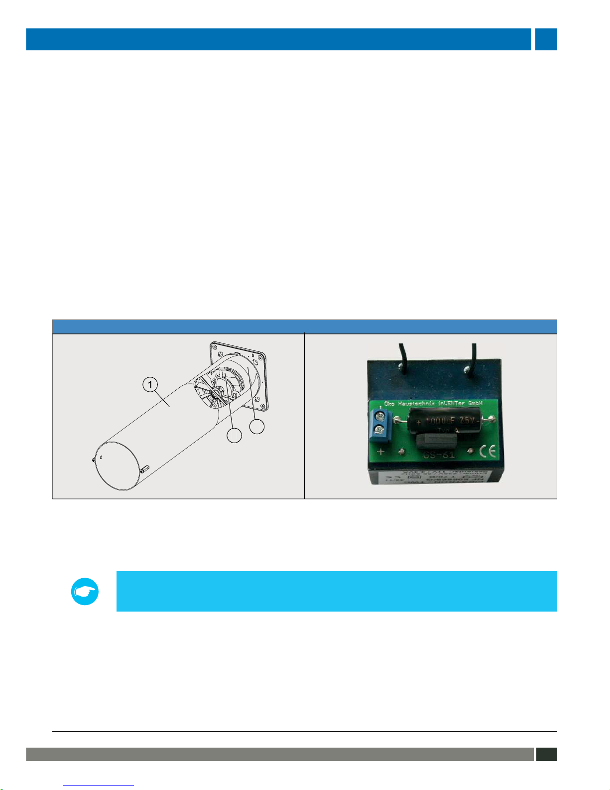
The base element of every variant is the combination of wall mounting sleeve (1), fan housing (2) with integrated
fan (3) and the GS61 PSU.
GS62 base element GS61 PSU
The GS62 can optionally be connected to the following modules, offering extended functionality as compared
to a standard On/Off switch*):
• R60 controller
• Delay switch
• Hygrostat
Note - The description and connection options of these modules are in additional,
accompanying installation and operating instructions for the GS61 air extraction system.
Interior room side
The ventilation system is covered by a baffle on the interior wall side. Inside baffles can be
ordered:
• in colors white/silver/stainless/gold (material: is plastic, curved shape)
• in opaque glass (straight shape)
• as a frame for affixing a glass or ceramic tile (material: plastic, straight shape)
*) The On/Off switch is not included in the delivery
6
GS62 Air Extraction System • Installation and Operating Instructions 09/2013
SYSTEM OVERVIEW
COMPONENT DESCRIPTION FEATURES ORDER NO.
GS62 - - 1001-0120
GS62-Corner 500 Comprising flat duct (500mm), 2 x wall
brackets and moffit grate
White 1506-0060
GS62-Corner 1000 Comprising flat duct (1000mm), 2 x wall
brackets and moffit grate
White 1506-0061
2-part telescopic tube Extension (500mm) for standard telescopic tube - 1002-0021
GS62 protective hood High-grade steel, powder-coated
White (RAL 9016) 1508-0043
Gray (RAL 7011) 1508-0044
High-grade steel, sanded Bare*
)
1508-0046
Inside baffle Plastic (curved) White 1505-0020
Stainless 1505-0021
Gold**
)
1505-0024
Silver **
)
1505-0025
Glass Opaque 1505-0022
Frame Decor of tile 1505-0023
R60 controller Fan speed regulator 1002-0006
Delay timer Button with integrated delay controller 1002-0011
Hygrostat Supports regulation of relative humidity 1002-0015
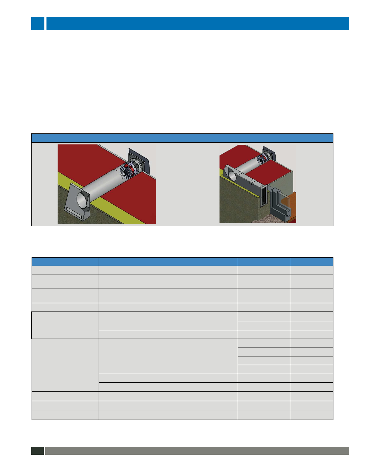
GS62 WITH PROTECTIVE HOOD GS62 WITH GS62-CORNER
Exterior room side
In the direction of the exterior room side, the ventilation system can be closed either with a
• protective hood (white/gray/bare
1)
) or
• the GS62-Corner 500 / GS62-Corner 1000, depending on preference and practical requirements
The GS62-Corner is used mainly when a building is retrofitted with insulation as part of renovation measures.
The air duct is embedded in the insulation and the airflow is directed out in the window reveal. The wall opening
for the ventilation system must therefore be in close proximity to the window. The GS62-Corner 500 is used
for a 250 … 450mm distance, the GS62-Corner 1000 for a 451 .. 950mm distance, between wall opening and
window reveal.
Validity
The installation and operating instructions apply for these elements:
*) Install only after coating (by customer) with Nano Set ,included
**) Not stock items (lead time on request)
7
DESCRIPTION
4
9 8 7
6
5
321
13
12
10
11
8 7 6
5
4
321
11
10
9
9
8
6
5
3
8
6
5
3
9
2 DESCRIPTION
The GS62 air discharge system is used to expel old air from a room. The fan is preinstalled in the housing for
ex works deliveries.
2.1 Features
• Low power consumption of fan (approx. 70% less than comparable AC fans)
• Use for wall thicknesses of 150 ... 550mm, to 950mm with telescopic extension
• Hole for telescopic tube Ø 115mm
• Use for distance between wall opening and window reveal of 350 ... 950mm (GS62-Corner)
• Combination of the base element with six inside baffles of different designs, shapes and colors,
and with three protective hoods of different colors, or the GS62-Corner in white
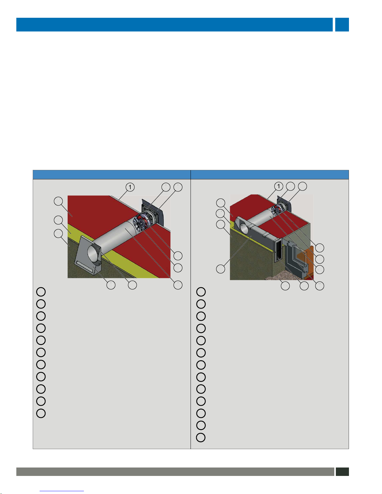
2.2 Assembly
GS62 WITH PROTECTIVE HOOD GS2 WITH GS62-CORNER
Interior plaster Interior plaster
Fan housing Fan housing
Inside baffle Inside baffle
Fan Fan
Nonreturn valve Nonreturn valve
Telescopic tube, 2-part (sleeve with tube) Telescopic tube, 2-part (sleeve with tube)
Protective hood rear panel Window
Protective hood cover Grate
Exterior plaster Window ledge
Insulation Duct
Masonry Exterior plaster
Insulation
Masonry
Figure 1: GS62 assembly
1
1
2
2
4
4
3
3
5
5
6
6
7
7
8
8
99
1010
1111
12
13

8
GS62 Air Extraction System • Installation and Operating Instructions 09/2013
OPERATING CONDITIONS
3 OPERATING CONDITIONS
Caution - Only use the GS62 in rooms that are free of aggressive and caustic gases, and
extreme dust exposure. This will ensure reliable functioning of the fan.
3.1 Telescopic tube
Standard variant
The length of the standard variant of the telescopic tube is 550mm, meaning it can be used for maximum wall
thicknesses of 550mm. For wall thicknesses of 325 ... 550mm, the telescopic tube is continuously adjustable.
The sleeve can be shortened by a maximum of 150mm for wall thicknesses shorter than 325mm.
Note - The minimum permitted wall thickness when using the standard variant of the telescopic
tube is 150mm.
The sleeve of the telescopic tube on the interior wall side is covered by the fan housing and an Inside baffle.
Extension
An extension is available as an option for walls having a thickness from 550mm to 1000mm (maximum). The
extension is a second telescopic tube without fan. The order number for the extension is under Validity in Section System overview.
2-part telescopic tube (extension)
Fan housing
Inside baffle
Fan
Nonreturn valve
2-part telescopic tube (sleeve with tube)
Protective hood rear panel
Protective hood cover
Figure 2: GS62 assembly with two telescopic tubes (extension)
3.2 Flat duct (GS62-Corner)
The length of the flat duct (GS62-Corner 500) is 500mm, and so can be used for gaps between wall opening and window reveal of 250 ... 450mm. If the gap between wall opening and window reveal is greater than
400mm, a flat duct 1000mm in length can be ordered as an option (GS62-Corner 1000).
Note - The maximum permitted gap between wall opening and window reveal is 950mm.
1
2
4
3
5
6
7
8
2-part telescopic tube (extension)
6

9
FUNCTIONAL ELEMENTS/INSTALLATION
4 FUNCTIONAL ELEMENTS / INTERFACES
4.1 GS61 PSU
Power supply (AC 230V, 50 Hz)
Fan connector (-)
Fan connector (+) or functional module (+)
Figure 3: Connectors on GS61 PSU
5 INSTALLATION
5.1 Installation preparation
Dimensions
Name Comprising: Length (mm) LxW / diameter (mm)
Hole for Wall thickness Ø 115
telescopic tube -
(with insulation, interior/exterior plaster)
Telescopic tube Sleeve 300 Ø 107
Tube 300 Ø 103
Extension Identical in design to combination Wall mounting sleeve / telescopic tube
Flat duct - 500 209x65
- 1000
Opening for - 87 Ø ≥ 75
wall mounting box
Wall mounting box - 87 Ø 73
Note - Keep a minimum distance of 100mm from the center of the wall mounting sleeve to
walls, to components in the interior area as well as to fixtures and fittings.
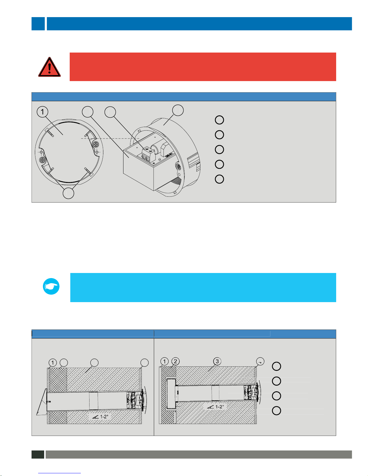
Wall holes and cable laying
Danger - Make the opening for the wall mounting box outside protective areas 0 to 2 of the
room. This will ensure that no moisture can penetrate in.
1. Make two holes in the masonry - one (Ø75) for the wall mounting box and one (Ø115) for the telescopic
tube. Ensure that the hole for the wall mounting sleeve of the GS62 is at an angle of 1-2° to the outside
wall so that condensation is drained away reliably.
2. Lay the 2-wire connecting lead (red/white) for the wall mounting box in the cable duct such that the cable
ends project out of each wall opening by at least 150mm. This ensures that the PSU and switch can be
connected with terminal blocks.
Note - The dimensional drawings for all holes are in Section Dimensional drawings.
1
1
2
2
10
GS62 Air Extraction System • Installation and Operating Instructions 09/2013
INSTALLATION INSTALLATION
5.2 PSU
Danger - Before starting any work on electrical systems, disconnect all relevant equipment
from the power supply. When wiring the power supply, observe the requirements of Safety
Class II.
GS61 PSU
Cavity
PSU
Fan connector (terminal, 2-pin)
Wall mounting box
Cavity separating wall
Figure 4: Fitting the PSU
1. Make two holes on the wall mounting box (4) - these must be in different cavities (1).
2. Separately guide the cables for the PSU and the fan through one hole each and insert the wall mounting
box.
3. Connect the fan cable to the PSU (2) using the 2-pin terminal (3).
4. Ensure correct polarity connections are made. Information on this is in Section Electrical connection.
Note - The wall mounting box must always be shut.
GS61 PSU - Attach a standard or optionally available On/Off switch. Order number informa-
tion is in Section Deliverables and accessories.
5.3 Telescopic tube
GS62 with protective hood GS62 with GS62-Corner
Exterior plaster
Insulation
Masonry
Interior plaster
Figure 5: Determining the wall thickness
1
1
2
2
4
4
3
3
5
3
Interior plaster
Exterior plaster
Insulation
Exterior plaster
 Loading...