


USBOSDM2 Ver. 1.0.0 Page 1 Application Software User Manual
USBOSDM2
USB-Powered MPEG2 Encoder with Picture-in-Picture & Text/Graphics Overlay
Application Software User Manual
Version 1.0.0
Copyright © 2010 Inventa Australia Pty Ltd
Table of Contents
1. Main Features & Functions ------------------------------------------- 2
2. Packages Contents ------------------------------------------- 3
3. Minimum System Requirement ------------------------------------------- 3
4. Hardware Installation ------------------------------------------- 3
5. Software Installation ------------------------------------------- 3
-- Device Driver Software Installation ------------------------------------------- 3
-- Application Software Installation ------------------------------------------- 4
6. Device Architecture ------------------------------------------- 5
7. User Interface ------------------------------------------- 5
8. Channel Setup ------------------------------------------- 7
-- Video Channel Setup ------------------------------------------- 7
-- Audio Channel Setup ------------------------------------------- 10
9. Overlay Setup ------------------------------------------- 10
-- Overlay Item, Type and Colour ------------------------------------------- 10
-- Text Overlay ------------------------------------------- 12
-- Timer Overlay ------------------------------------------- 13
-- Rectangle Overlay ------------------------------------------- 14
-- Box Overlay ------------------------------------------- 14
-- Graphics File Overlay ------------------------------------------- 14
-- Overlay Item Options ------------------------------------------- 14
-- Overlay Items Overlap Priority ------------------------------------------- 15
10. Device Setup ------------------------------------------- 15
11. Recording Video ------------------------------------------- 17
-- Setup Recording ------------------------------------------- 17
-- Start, Pause, Stop Recording ------------------------------------------- 20
12. Streaming Video ------------------------------------------- 21
-- Setup Streaming ------------------------------------------- 21
-- Start and Stop Streaming ------------------------------------------- 22
13. Grab Still Image ------------------------------------------- 22
14. Other Drop-down Menu Selections ------------------------------------------- 22
15. Use Multiple Devices ------------------------------------------- 23
16. Command Line Parameters ------------------------------------------- 23
17. Default Parameter Values ------------------------------------------- 24
18. Menu Hotkeys ------------------------------------------- 26
19. Technical Discussions ------------------------------------------- 26
20. Hardware Specifications ------------------------------------------- 27

USBOSDM2 Ver. 1.0.0 Page 2 Application Software User Manual
1. Main Features and Functions
USBOSDM2 is a multi-I/O, colour OSD and hardware MPEG USB encoder with many powerful features:
--- Real-time encode MPEG1, MPEG2 video from 1 Mbps to 25 Mbps using hardware compression chipset
--- Encode 4 video input into one MPEG stream as picture-in-picture in arbitrary position and size
--- Encode unlimited colour text/graphics overlay (OSD) items as integral part of the MPEG video
--- Fully USB-Powered, no AC adaptor is needed
--- Real-time live preview video on PC screen in arbitrarily re-sizable and movable window or full screen
--- 2 set of video/audio output sockets allow real-time output inc. picture-in-picture and OSD to external TV
--- 4 Video Input Channels software-selectable from 5 Composite and 1 SVideo Sockets
--- 4 Audio Input Channels software-selectable from 4 Stereo Line-in and 2 Stereo Mic. input sockets
--- Perfect Audio/Video Synchronization is always maintained in the recorded and streamed MPEG video
--- Record video as MPEG files: files can be manually split or automatically split at fixed time or length
--- Record using timer or calendar scheduler with daily or weekly repeat options
--- Real-time stream video over IP network multi-cast or uni-cast independent of file recording status
--- Real-time flip/mirror any input video horizontally or vertically
--- Real-time enlarge input video at any point inside video frame (2-times zoom-in)
--- PAL and NTSC encoding at 720X576, 720X480, 480X576, 480X480, 352X288, 352X240-Pixels
--- DVD, SVCD, VCD, MPEG2, MPEG1 encoding format fully user-selectable
--- Multiple USBOSDM2 devices (up to 8) can run simultaneously on one PC under the same software
--- OSD on video include text, timer, graphics, rectangle, and box, with selectable colour, alpha and blink
--- OSD text/timer can use any PC font in any size, typeface, style, colour, in transparent or opaque mode
--- Each input video channel can have boundary on or off
--- Each input video channel has colour brightness, contrast, hue, saturation and sharpness control
--- Each input audio channel has hardware gain control and left/right mute
--- Recording file name can have user-defined fields inc. recording quality, date/time, serial number etc
--- Still images can be grabbed in bmp, jpg, gif, tiff, and png format
--- Live recording status can be displayed inside video frame with user-definable colour and font
--- Colour Bar generation to test video output capability
--- Can record/stream MPEG Video with Text/Graphics Overlay when no input signal is available
--- Optional Comprehensive
Software Development Kit (SDK) for writing customized application software

USBOSDM2 Ver. 1.0.0 Page 3 Application Software User Manual
2. Package Contents
USBOSDM2 comes with the device box, application software, USB and video/audio cables.
3. Minimum System Requirement
Hardware: Intel-Pentium4/AMD-Athlon PC with 2 USB2 sockets, 512MB RAM, 128MB Video card.
Software: MS Windows7, Vista or XP SP2, DirectX9 with DirectDraw Hardware Acceleration enabled.
Operating Environment Temperature: Below 30 °C.
4. Hardware Installation
Plug the two USB cables into the PC’s USB sockets, note sockets from separate USB Hubs are NOT
recommended because they usually cannot support enough power to run USBOSDM2 properly.
Connect any video/audio device’s video/audio output sockets to the input sockets on USBOSDM2.
Optionally, VCR or TV can be connected to the TV OUT 1 or TV OUT 2 sockets.
Note 1: All USBOSDM2 devices must be connected and device driver installed before the application
software can start, USBOSDM2 device cannot be added or removed when the software is running.
Note 2: Do not plug cables to both the rightmost “SVideo” & “CVBS” sockets, use one at a time only!
5. Software Installation
Installation includes Device Driver software and Application software (the optional SDK software
installation is described separately in its own manual), either one can be installed first:
Device Driver Software Installation
Once the USBOSDM2 device is connected to a PC, the Windows will inform new device is found and
ask for the location of device driver software: indicate to Windows the device driver software is located
either at the installed application software folder (usually C:\Program Files\Inventa\USBOSM2) or on
the Setup CD, ignore Windows’ warning messages claiming the driver was not passed Windows’ Logo
testing etc., proceed to install the device driver until two device drivers -- “Inventa MPEG-2 Box” and
“Inventa USBOSD” -- appear under the “ControlPanel->System->Hardware->DeviceManager->Sound,
video and game controllers” category without question mark and exclamation mark:
Note 1. For multiple USBOSDM2 devices, each device will have a pair of “Inventa MPEG-2 Box”
and “Inventa USBOSD” drivers listed.

USBOSDM2 Ver. 1.0.0 Page 4 Application Software User Manual
Note 2. USB devices with the same hardware IDs as USBOSDM2, like Inventa’s “USBMPEG2-Box”,
DVICO’s FusionMPEG2, etc., should not be used simultaneously with USBOSDM2 on the same PC.
Application Software Installation
Once the Setup CD is inserted into PC’s CD drive, the “Setup Wizard” window will appear:
If this window does not appear double-clicking the “Start.exe” file on the CD can bring up this window.
From this window, proceed to install USBOSDM2’s application software ---- this can be done either
before or after the device driver has been installed as described in the previous section.
Note the end of installation is the “Filters Registration Completed” window: click the “OK” button on
this window will finish the application software installation and put the icon on the Windows’
desktop. Mouse double-clicking this icon will launch USBOSDM2 application software: it can also be
launched (or un-installed) from Windows’ “Start->All Programs->Inventa->USBOSDM2” menu.

USBOSDM2 Ver. 1.0.0 Page 5 Application Software User Manual
6. Device Architecture
USBOSDM2 contains several major hardware/software processing units as illustrated below:
As seen in the picture, USBOSDM2 can be viewed as consisting of an OSD device and an M2B device:
input signals are first mixed, geographically arranged and text/graphics overlaid by the OSD device,
then MPEG-compressed, recorded, streamed and live-previewed on PC by the M2B (MPEG2-Box)
device. This two-device principle has been used throughout the USBOSDM2 Application Software
programming and therefore will be followed similarly in this software user manual. Note on the device’s
back panel, the bottom USB socket is for the OSD device, the top USB socket is for the M2B device.
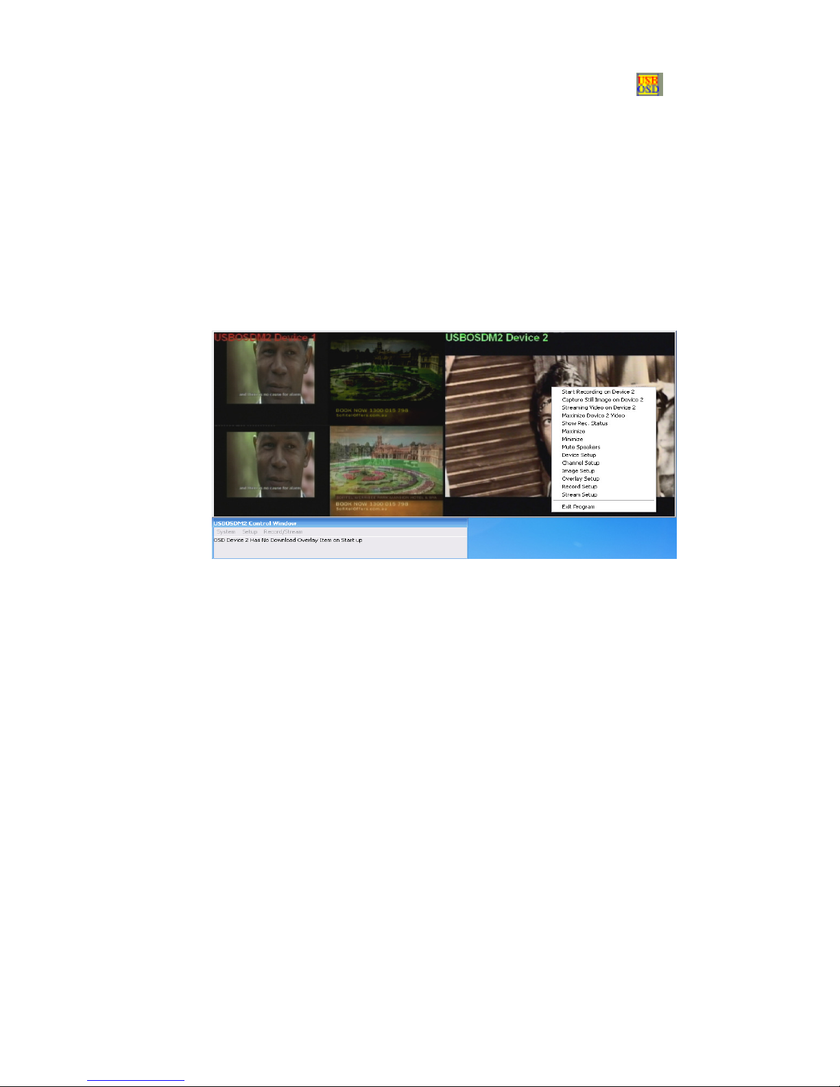
7. User Interface
On start up, USBOSDM2 software presents a Video Window and a Control Window on PC screen:
Right-mouse single clicking inside the Video Window will also display a Drop-down Menu:

USBOSDM2 Ver. 1.0.0 Page 6 Application Software User Manual
a. Control Window
The Control Window allows menu items to be selected from top-level main menu System,
Setup, or Record/Stream:
;
it also displays operation feedback status at the area below the menu bar. Left-mouse clicking
the title area of the Control Window then dragging it will move the Control Window and the
Video Window together around PC screen. The entire program can be ended by selecting
“System->Exit Program” menu item.
The Control Window cannot be resized but will become hidden on the Windows’ Taskbar together
with the Video Window when “System->Minimize” menu item is selected.
b. Video Window
The Video Window is always located above the Control Window: it can be resized by left-mouse
clicking its edges then dragging in any direction. Left-mouse double-clicking inside Video Window
will make it to enter Full-Screen mode: video content will occupy the entire desktop area in front of
all other windows (double-clicking again or pressing the Space-Bar will revert back to normal
window mode).
Left-mouse single-clicking inside Video Window then dragging it will move the Video Window
and Control Window around the desktop area together.

USBOSDM2 Ver. 1.0.0 Page 7 Application Software User Manual
When multiple USBOSDM2 devices are connected, all devices’ video contents will be displayed
inside the Video Window from left to right each with equal width.
Video Window can also show a USDOSBM2 device’s recording status when recording is started.
c. Drop-down Menu
Drop-down Menu appears when Right-Mouse-Button is singled-clicked inside the Video Window.
Apart from displaying various menu items for selection, the Drop-down Menu also reflects one
USBOSDM2 device’s status: if recording is on, paused or off, streaming is on or off, recording
status is on, audio speakers are muted, etc.
8. Channel Setup
The Channel Setup window controls video and audio channels’ incoming signal configuration and
channel video window arrangement. This window can be brought up from the Control Window’s
Setup->Channel Setup menu item, or from the Drop-down Menu-> Channel Setup:
a. Video Channel Setup
i. Video Channel Features
Each OSD Device has 4 simultaneously available video input channels named as Chan1 ~
Chan4: each of them has its own video window inside the Device’s entire video frame and can
be individually arranged inside the OSD Device’s video frame, it is this entire video frame
consisting of the 4 video channel windows that will be sent to the M2B Device to be encoded as
one MPEG video stream then recorded as one file or streamed out over IP network. Each video
input channel has its own features to be setup:
Input Source: From which socket this channel receives video signal – can be one of Input1,
Input2, Input3, Input4 or Input5, corresponding to the Input Video Sockets on the front of
USBOSDM2 device box: the Input1~Input4 sources always use Composite(RCA) socket, while
the Input5 source can select either CVBS(same as RCA) or SVideo socket (Do not plug cables
into these two sockets for Input5 simultaneously, use one at a time only!). Note more than one
channels can simultaneously receive signal from the same Input Source.
Disable Video In: Disable video input to this channel: will not affect other channels’ video input.

USBOSDM2 Ver. 1.0.0 Page 8 Application Software User Manual
On Top: If this channel has display priority over other channels when this channel overlaps with
other channels. When two or more video channels overlap, how to display the overlapped area
depends on this display priority: channels with “On Top” ticked have higher priority than
channels that do not have “On Top” ticked. If two channels have the same “On Top” ticking or
not-ticking status, then the lower-numbered channel has higher display priority. For example, if
channel 1 and channel 2 overlap, the overlapped area will show channel 1’s video if both
channels have “On Top” ticked or not ticked in the same way. However, if channel 1 has “On
Top” not ticked while channel 2 has “On Top” ticked, then the overlapped area will show
channel 2’s video.
Window Cropping: How many pixels from left or top of the original raw video frame will be
chopped off, and how many pixels in width and height a video frame will have. When
USBOSDM2 hardware digitizes incoming analogue video, it generates an original raw video
frame larger than PAL or NTSC video frame’s standard 720X576 or 720X480 pixel size,
Window Cropping defines the left, top, width and height positioning of a standard PAL / NTSC
video frame fetched out of the original raw video frame. Note for PAL incoming signal, it’s
highly recommended to select 720X576 as its width and height; for NTSC incoming signal,
select 720X480 as its width and height, otherwise erroneous display effect could appear.
Window Position: The upper-left position and width, height of a channel’s video window inside
the entire video frame: width and height should not exceed a video frame’s 720X576 (PAL) or
720X480(NTSC) maximum width and height. Click the “Apply” button to make these changes
effective: this will also reset the M2B device and cause the video frame content to be re-drawn –
therefore clicking this button can also be used to rectify some erroneous video display problems.
Note Window Position cannot be changed when Video Window is in Full Screen Mode.
Common Positions: Select from some commonly used video window sizes and positions:
Note 1: For Window Cropping, PAL and NTSC have different default values:
For PAL: Left=15, Top=10, Width=720, Height=576: 720/576 are the max. pixels;
For NTSC: Left=15, Top=12, Width=720, Height=480: 720/480 are the max. pixels.
Note 2: The default “4 Channels” Common Position uses different values for PAL and NTSC:
For PAL: Channel 1 Left=0, Top=0, Width=360, Height=288
Channel 2 Left=360, Top=0, Width=360, Height=288
Channel 3 Left=0, Top=288, Width=360, Height=288
Channel 4 Left=360, Top=288, Width=360, Height=288

USBOSDM2 Ver. 1.0.0 Page 9 Application Software User Manual
For NTSC: Channel 1 Left=0, Top=0, Width=360, Height=240
Channel 2 Left=360, Top=0, Width=360, Height=240
Channel 3 Left=0, Top=240, Width=360, Height=240
Channel 4 Left=360, Top=240, Width=360, Height=240
Note 3: Selecting any common position will reset the M2B device and redraw video frame.
Note 4: Common Position cannot be selected when Video Window is in Full Screen Mode.
Mirror: Flip this channel’s video content horizontally and/or vertically:
Chan Boundary: Draw boundary around this channel’s video
window edges.
Brightness, Contrast, Hue, Saturation, Sharpness: The value ranges of these features are
different between video source Input1~Input4 and video source Input5, note the U Saturation /
V Saturation mean U / V component saturation in a YUV colour space, and this is only
applicable to Input1~Input4 video sources, Input5 video source only has Saturation.
Signal Standard, Signal Field Rate: When a video channel has incoming signal, these are
automatically detected and set. When a channel has no signal, the Signal Field Rate will
indicate “No Signal”.

USBOSDM2 Ver. 1.0.0 Page 10 Application Software User Manual
ii. Common Features
Default Field Rate: When all 4 video channels have no incoming signal, the value of this field
decides the current TV Signal Type: 50Hz for PAL and 60Hz for NTSC. When no signal is
available on any channel, selecting this value will reset the M2B device and redraw video frame.
PAL and NTSC TV Signal Type: USBOSDM2 does NOT support simultaneously mixed PAL
(50Hz Field Rate) and NTSC (60Hz Field Rate) TV signal types among its input sockets: TV
signals fed to all input channels should be of the same type: their Field Rates should be either all
50Hz or all 60Hz. If there are channels that receive TV signals of different type, the signal type
of the lowest number input channel having signal will be treated as the current TV signal type,
therefore channels with signal type different from the very first channel with signal might not be
displayed properly. When input signal changed Field Rate (PAL to NTSC or NTSC to PAL),
make sure the Window Cropping and Window Position described previously are set to PAL or
NTSC required values.
M2B Setup: This is the same as the “Encoding Properties” button on the “Record Setup”
Window, see the “Record Setup” section later in this manual for details.
b. Audio Channel Setup
Each USBOSDM2 device has 4 simultaneously available stereo audio input channels (i.e., each
channel contains left and right sub-channels): audio signals coming from these channels are
mixed and digitized into one digital stereo audio stream by the OSD device. Audio Channel 1
and 2 can select signal source from either their corresponding stereo Line-in sockets or stereo
Microphone sockets, while Audio Channel 3 and 4 can only receive signal from their
corresponding stereo Line-in sockets:
Audio channel 1 signal source: Stereo Line-in socket 1 or Stereo Mic. socket 1
Audio channel 2 signal source: Stereo Line-in socket 2 or Stereo Mic. socket 2
Audio channel 3 signal source: Stereo Line-in socket 3
Audio channel 4 signal source: Stereo Line-in socket 4
The Mute function has different meanings between audio channels 1 ~ 3 and audio channel 4:
audio channel 4 allows its left and right sub-channels to be individually muted/un-muted, while
audio channel 1 ~ 3 must mute or un-mute their left and right sub-channels simultaneously.
Audio Gain controls each audio input channel’s signal strength: this will be reflected in the
recorded / streamed MPEG video stream as well as in the PC’s speaker output.
The Volume and Balance controls inside the PC Speaker Audio group affect only PC Speaker
output, audio in the compressed MPEG stream cannot be affected by these changes.
9. Overlay Setup
a. Overlay Item, Type and Colour
The Overlay Setup window controls how text and graphics items (Overlay Items) are overlaid on
the surface of the video frame, regardless if video signal is available at any video input channel. This

USBOSDM2 Ver. 1.0.0 Page 11 Application Software User Manual
window can be brought up from the Control Window’s Setup->Overlay Setup menu item, or from
the Drop-down Menu-> Overlay Setup:
Overlay on video frame is accomplished by creating Overlay Items: each item has an Overlay
Type. Currently supported Overlay Types include Text, Timer, Rectangle, Box and Graphics File:
.
Every overlay item is associated with some options such as font, colour, alpha, blinking, etc.
Overlay Items can be added, modified, deleted and redrawn. To create a new overlay item, first
select an Overlay Type, fill in relevant options such as Start X/Y position, Font, Text etc., then
click the Add Item button, the overlay item will appear on the video frame and output TV monitor.
If recording is in progress, overlay will also be recorded into MPEG video file immediately.
Note 1: When drawing overlay item onto video frame, pressing Esc key can abort the operation:
aborting overlay painting requires hardware reset on OSD and M2B devices so do this with caution.
Note 2: Avoid extending an overlay item’s ending edges beyond video frame’s limits (720/576/480).

USBOSDM2 Ver. 1.0.0 Page 12 Application Software User Manual
Most overlay items use colours --- foreground colour or background colour or both. At any given
time, USBOSDM2 hardware allows 251 different colours to be used simultaneously on the video
frame: these 251 colours can be selected out of the 16-Million or so possible colour combinations
(256 Red, 256 Green and 256 Blue). The currently selected 251 colours form a “Colour Palette” or
“Colour Lookup Table”. When first started, USBOSDM2 uses a default Colour Palette: this can be
viewed by clicking the “Test Colours” button. Colour Palette can be changed when Graphics File
Overlay Item is used: see more details in the Graphics File Overlay section.
b. Text Overlay
To use Text Overlay item, the edit field next to the “Text:” must have text. The text’s type face,
size, style, colour etc. can be selected in the Font window after clicking the “Font” button:
The “Font” used by Text overlay can be either non-downloaded (default, “Use Downloaded Font”
is cleared), or “Downloaded” (“Use Downloaded Font” is ticked): non-downloaded means when
each character used in a text overlay is being painted onto video frame, its bitmap is downloaded to
USBOSDM2 device at that time; Downloaded means first downloading all characters’ bitmaps of
the current font onto USBOSDM2 device, then using each character’s downloaded bitmap to paint
the text overlay onto the video frame(without downloading the characters’ bitmaps again). The
main advantage of using downloaded font is to display the text overlay quickly, although the one
time downloading of the entire font’s bitmaps will usually take much longer time. Downloaded font
also cannot have Opaque background mode nor the Alpha/Blinking options (see below).
USBOSDM2 allows four 720X576-Pixel memory pages to hold possible downloaded fonts:
clicking the “List Font” button will show all downloaded fonts’ character bitmaps currently
available in the on-board memory, e.g. 3 downloaded fonts are listed like this:

USBOSDM2 Ver. 1.0.0 Page 13 Application Software User Manual
Each downloaded font has bitmap images for characters with ASCII values 0x20 ~ 0x7F (printable
characters), therefore only these characters can be used with downloadable fonts.
The text colour can also be selected from the Foreground Colour window by clicking the “FrGr
Colour” button: this allows much more possible colour selections than the “Color” combo selection
inside the Font selection window --- however, if a colour selected in the Foreground Colour
window is not among the limited number of possible colours inside the Font window’s Color
combo box, the Font window will always display black colour.
The Text overlay has a Background Mode (BkGr Mode) option: this can be either Transparent
(default) or Opaque. If Transparent is selected, the spaces in between a character’s strokes will
expose the background video content. If Opaque is selected, these spaces will be filled with the
Background Colour (BkGr Colour), as seen here: .
The Alpha option allows less than fully visible text to be painted on video frame:
smaller alpha value means less visibility, default is no alpha(full visibility).
The Blink option enables the text to blink at certain frequency: , default is no blinking.
Note text using Downloaded font cannot have Opaque background mode, nor Alpha or Blinking
option.
c. Timer Overlay
Timer is a special case of Text overlay: it displays only current time text on video frame in one
second interval. Timer overlay also has no Blink option (cannot blink). The Timer Format
option allows either time only or date & time to be displayed:
.
Timer Overlay is a typical example of using “Downloaded Font” text overlay: each time a new
Timer Overlay is created, all 12 possible characters’ bitmaps are first downloaded onto
USBOSDM2 device’s on-board memory, per-second time updates come after this downloading
finishes, this way an instant change of text is accomplished within every second.
Only one Timer overlay item is allowed for each USBOSDM2 device.

USBOSDM2 Ver. 1.0.0 Page 14 Application Software User Manual
d. Rectangle Overlay
Rectangle overlay allows drawing coloured rectangles on video frame: minimum width (the W:
field) and height (the H: field) are 2 pixels. Rectangle drawn is filled with foreground colour, but
has no background mode nor background colour.
e. Box Overlay
Box overlay is a special overlay type that has several features different from the Rectangle overlay:
Only 4 Box overlay items are available for each USBOSDM2 device
No Blink option for Box overlay
Box overlay can have white Boundary
Apart from the foreground colour, Box overlay can also use some pre-defined “Box Colour”
Box overlay and Text overlay can be overlapped to form some “Text with partially transparent
background” effect, such as this: .
When Box overlay item is overlapped with other overlay items, Box overlay is always on top.
f. Graphics File Overlay
Graphics File overlay allows BITMAP, JPEG, GIF etc files to be overlaid on the video frame. Files
used must have 256-colour palette, byte-aligned in width, and be DIB section --- normal graphics
editing programs such as Microsoft Paint and Adobe PhotoShop etc. can create these graphics files.
When a graphics file is loaded as overlay, its Palette can be optionally loaded to replace the default
Palette (by ticking the Use Palette check box) ---- although doing so might improve the overlaid
graphics quality, it will also affect the colours used to draw other type of overlay items, such as text
or timer. Therefore when using Graphics File overlay with “Use Palette” ticked, it’s better to create
it before creating other overlay items such as text or timer. Graphics File overlay cannot Blink.
g. Overlay Item Options
Current Item: Number of the current overlay item whose options are displayed on screen.
Changing this will change other option values accordingly to reflect newly selected overlay item.
Overlay Type: Select a type here before creating new overlay item. When Current Item value
changes, this field reflects the current item’s overlay type.
Disable Overlay: Disable/Enable all overlay items on video frame.
Use Downloaded Font: The current overlay item’s text will use downloaded font.
Download Item on Start: Overlay items with this box ticked will be automatically re-drawn
when USBOSDM2 program is started: this will take long time if too many items are defined.
Download: Download the current font to OSD device: big font can take long time to download.
Delete: Delete the current downloaded font.
List Font: List all fonts already downloaded onto the RAM of OSD device.
Clear Screen: Erase all overlay contents from the video frame without deleting the overlay
items. After a Clear Screen operation, any existing overlay item can be re-displayed by clicking
the “Redraw” or the “Redraw All” button.
Test Colours: List all colours of the current Palette (Colour Lookup Table) used.
Add Item: Create a new Overlay Item.

USBOSDM2 Ver. 1.0.0 Page 15 Application Software User Manual
Modify Item: Modify the current overlay item using the various new option values on the screen.
Delete Item: Delete the current overlay item.
Delete All: Delete all overlay items.
Redraw All: Redraw all existing overlay items.
Redraw: Redraw current overlay item using its existing option values (ignore on-screen options).
FrGr Colour: Set Foreground (pixels’) Colour for Text, Timer, Box, Rectangle Overlay Items.
BkGr Colour: Set Background Colour for Text/Timer/Graphics File Overlay. If “Transprent” is
used for “Bkgr Mode”, pixels on overlay item with this colour will become transparent (video
behind these pixels become visible): similar as the “Blue Screen” effect in video editing process.
Bkgr Mode: Set Background Mode (Transparent/Opaque) for Text/Timer/Graphics File Overlay.
Timer Format: Select to display Time Only or Date+Time for Timer Overlay Item.
Text: The text content for Text Overlay Item.
File: Load a file for Graphics File Overlay, note large graphics can take long time to load.
Alpha: The visibility of the current overlay item: lower alpha value means less visible. Note
each USBOSDM2 device can only have one Alpha value at a time: if one Overlay Item defines
a new Alpha value (either 0.25, 0.5, or 0.75) then all overlay items having Alpha values defined
previously will be using the same Alpha value (overlay items having None as their Alpha values
will not be affected).
Blink: Blinking time interval of the current overlay item. Note each USBOSDM2 device can
only have one Blink time interval at a time: if one Overlay Item defines a new Blink time (either
0.25, 0.5, 1 or 2 seconds) then all overlay items having Blink defined previously will be using
the same Blink time (overlay items having None as their Blink values will not be affected).
Start X, Start Y: Upper left corner of the current overlay on video frame, resolution is 2-pixels.
W, H: The Width and Height of the Rectangle or Box Overlay Item, resolution is 2-pixels.
Boundary: Enable boundary for Box Overlay Item.
Box Colour: Select pre-defined colour as the filling colour for Box Overlay Item.
h. Overlay Items Overlap Priority
When two or more Overlay Items’ contents are overlapped on video screen, the more recently drawn
items are always on top of the previously drawn items’ contents, with the exception of the Box
Overlay which is always on top of the non-Box overlay items’ content.
10. Device Setup
The Device Setup window controls functions affecting the entire USBOSDM2 device’s operation. This
window can be brought up either from the Control Window’s Setup->Device Setup menu item, or
from the Drop-down Menu-> Device Setup:

USBOSDM2 Ver. 1.0.0 Page 16 Application Software User Manual
Colour at No-Channel-Area: Select the colour used to paint the areas inside this OSD Device’s
video frame that are not occupied by any video channel, default is grey colour:
Disable M2B Device: Disable the M2B device, resulting in a freeze of OSD Device’s video
content: this will take some time to finish and will revert to No when leaving this device’s setup.
Disable OSD Video Out: Stop video signal leaving the OSD device, resulting in total black out
of this OSD Device’s video content.
Disable OSD Video In: Stop video signal input to OSD device at all of the four video channels.
Zoom Video: When enabled, left-mouse clicking inside this OSD Device’s
video frame while holding down the Ctrl key will enlarge (Zoom) the video content by 2 times
from the clicked pixel along the vertical (Y) and / or the horizontal (X) direction. To cancel the
Zoomed mode, left-mouse click anywhere in this OSD Device’s video frame without holding
down the Ctrl key. Zoom Video will not work when Video Window is in full screen mode.
Colour Bar: Display Colour Bar as this OSD Device’s video content in front of any input signal.
SVideo Link: Using SVideo or Composite Link between OSD and M2B devices. If SVideo is
used, TV OUT 1 will connect to the SVideo’s Y signal pin so will output black & white signal.
TV2 on YX: If TV OUT 2 connects to the Y signal pin of the OSD device’s SVideo output
when SVideo Link is used (Default is TV OUT 2 connects to OSD device’s Composite output).
Confirm on Exit: If to display a confirmation dialog before exiting the USBOSDM2 program.
Rec. Timer Expire Exit Program: Exit USBOSDM2 software when recording ends because
timer expires: if any device is still recording or any dialog is still open the exit will not happen.
Rec. Timer Expire Shutdown PC: Shutdown PC when recording ends because recording timer
expires: if any device is still recording or any dialog is still open the shutdown will not happen.
M2B Setup: Same as the “Encoding Properties” button on the “Record Setup” Window.
Reset M2B Device: Hardware reset the M2B device: this will take some time to finish.
Reset OSD Device: Hardware reset the OSD device: can correct errors like no video display etc.
OSD Init Vals: Load an .ini file to OSD device: such as OSDValsPAL.ini, OSDValsNTSC.ini.
Show Rec. Status: Display on-screen recording status when MPEG file recording is in progress.
Status Transparent: The recording status is in transparent (exposing background video) mode.
Rec. Status Font: Define recording status text font: adjust this to make status line fully visible.
Status Bk Colour: Change recording status’ background colour if it’s not in transparent mode.
Status Start Line: The 1st row of the status pixels: max. is approx. 570 (PAL) or 470(NTSC).
DirectX Settings: Windows’ Video Rendering options, need a Reset M2B after changing these:
--- Sample Format: Method used by the M2B device to sample video frames.
--- Deinterlace Mode: Method used by the M2B device to de-interlace video.

USBOSDM2 Ver. 1.0.0 Page 17 Application Software User Manual
11. Recording Video
a. Setup Recording
Record Setup Window controls how MPEG files are recorded; it can be brought up from either
Control Window->Setup->Record Setup menu item, or Drop-down Menu-> Record Setup:
Recording Device: Select device number when multiple USBOSDM2 devices are connected.
Current Recording Path: The folder for recorded files, double clicking a disk or folder name in the
list-box will show sub-folders under it, currently selected folder is above the list-box.
Timer: If recoding timer is set in minute unit, recording will stop at that time length. Zero (default)
timer value means no timer: record can only be stopped by user manually or when disk is full.
Scheduler: Starts Recording Scheduler window to schedule recordings in future time:

USBOSDM2 Ver. 1.0.0 Page 18 Application Software User Manual
Start Hour is in 0~24 hour format, e.g. 7:30PM is expressed as Hour: 19 Min. 30.
Repeat indicates how a scheduled recording will repeat: once only or daily or weekly.
File Name Prefix (FNP) is used as the first part of the scheduled recording file name, the scheduled
recording file name is usually formed as: FNPDateTime.mpg, where FNP must not contain space
character and is maximum 20 bytes. Note scheduled recording file names will not follow the
methods described in the “Name Recording File” section below.
Use GMT in File Name/Date/Time: if ticked, the date/time is according to Greenwich Mean Time
(or UTC -- Coordinated Universal Time), otherwise (default) local time is used.
No Date in File Name: if ticked, scheduled recording file name is formed as FNPTime.mpg.
No Time in File Name: if ticked, scheduled recording file name is formed as FNPDate.mpg.
The Add, Modify, Delete buttons are to add, modify and delete scheduled recording. Schedule a
recording prior to current time will have no effect.
Name Recording File: This decides how non-scheduled recording will form file names:
Prompt Before Recording:
Each time before recording starts a dialog will appear asking for file name.
Prompt After Recording:
Each time when recording stops a dialog will appear asking for file name.
Pre-name as Text:
Creating recording file name using “File Name Fields” as defined in the “Recording File
Name Fields” Window (after clicking the Setup File Name Fields button):
Each Field in file name can be used at most once. “Field Separator” is used to separate
between two fields. When recording starts, duplicated file name will be silently overwritten
without warning.
Note recorded file names will always be appended with .mpg as file name extension.
Split Recording File:
During MPEG file recording, current file can be closed and new file can be started. Automatic file
splitting method can be pre-defined here: Split at File Size will split a new MPEG file when current
recording file size reaches a certain MBytes, while Split at Record Time will split a new MPEG
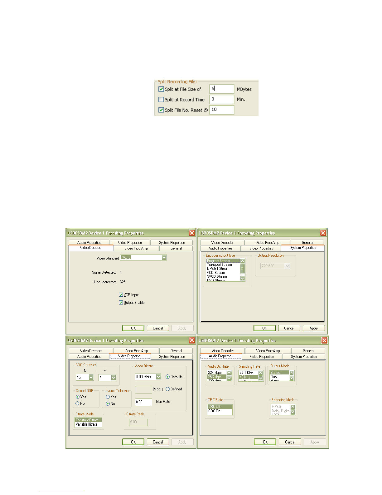
USBOSDM2 Ver. 1.0.0 Page 19 Application Software User Manual
file when current recording file reaches a certain minutes. The split file name is formed by
appending an 8-digit serial number (starting from 00000001) to the initial recording file name: each
time a new file is split, this 8-digit serial number will increase by 1. If “Split File No. Reset” is set
to non-zero, this 8-digit serial number will reset to 1 when reaching this non-zero number. For
example, using the following Split Recording File settings,
,
MPEG files recorded can have these names repeatedly with each file sized at approx. 6MBytes:
MPEGRecord1_20091026_151904_Video8000Kbps.mpg
MPEGRecord1_20091026_151904_Video8000Kbps_00000001.mpg
MPEGRecord1_20091026_151904_Video8000Kbps_00000002.mpg
… …
MPEGRecord1_20091026_151904_Video8000Kbps_00000010.mpg
Manual File Splitting can be done through the Drop-down Menu->Split-Recording File.
Encoding Properties: This window is for setting up MPEG encoding options, including MPEG file
format in System Properties tab window, MPEG Video Bit Rate, GOP Structure in Video
Properties tab window, MPEG Audio Bit Rate and Sampling Rate in Audio Properties tab
window, and overall Video Content Colours in Video Proc Amp tab window:

USBOSDM2 Ver. 1.0.0 Page 20 Application Software User Manual
Several Notes on settings in these encoding properties windows:
Note 1: To create DVD/SVCD/VCD movie disks playable in stand-alone DVD players,
DVD/SVCD/VCD encoding need to follow their respective standard settings:
DVD: Video Bit Rate: 4 ~ 10 Mbps, Audio Sampling Rate: 48 Khz
SVCD: Video Bit Rate: 2.5 Mbps, Audio Sampling Rate: 44.1 Khz
VCD: Video Bit Rate: 1.15 Mbps, Audio Sampling Rate: 44.1 Khz
Note 2: In “System Properties” tab window, “Program Stream” and “Transport Stream” will
have the same result: both create Program Stream MPEG2 video.
Note 3: Exiting from Encoding Properties Window will always cause a reset of the M2B
device: the entire Video Window content will be re-drawn.
Note 4: The “M2B Setup” button under Channel Setup and Device Setup windows actually
invoke this same “Encoding Properties” window.
b. Start, Pause, Stop Recording
MPEG video recording can be started from Drop-down Menu->Start Recording, or from Control
Window->Record/Stream->Start Record/Stream. Drop-down Menu->Start Recording always
starts recording on one device, while Control Window->Record/Stream->Start Record/Stream
selection can simultaneously start multiple USBOSDM2 devices recording if they are available:
Similarly as starting record, manually stopping record can also be initiated either from USBOSDM2’s
Drop-down Menu->Stop Recording ------ which always stops recording on one USBOSDM2 device,
or from Control Window->Record/Stream->Stop Record/Stream, which allows stopping recording
on multiple devices if they are present:
.
When Timer has non-zero value, recording will stop automatically when timer expires.
During video recording process, select Drop-down Menu->Pause Recording will temporarily pause
writing data to the recording file without closing the file:

USBOSDM2 Ver. 1.0.0 Page 21 Application Software User Manual
.
Paused recording can be resumed by selecting Drop-down Menu->Resume Recording.
Pause/Resume can also start from the Control Window->Record/Stream->Pause Record window:
12. Streaming Video
a. Setup Streaming
USBOSDM2 can act as a Streaming Server sending out MPEG video over IP network in UDP format.
The Streaming Video Window can be brought up either from Drop-down Menu->Stream Setup, or
from Control Window->Setup->Stream Setup:
To uniquely identify a receiving party for video streaming, an IP Address and a Port Number need to
be supplied. USBOSDM2 can stream out MPEG video in either Multicast or Uni-cast UDP mode:
Multicast streaming allows multiple receiving parties to receive the same MPEG video simultaneously,
while Uni-cast allows only one receiving party at a time. To stream in Multicast mode, a Multicast
address (usually in the range of 224.0.0.0 ~ 239.255.255.55) must be entered in the IP Address field
under the “Streaming Target IP” title, and the Multicast box must be ticked. The default mode is Unicast streaming.
USBOSDM2 Ver. 1.0.0 Page 22 Application Software User Manual
b. Start and Stop Streaming
In the Streaming Video Window, ticking or clearing the check box will start or stop
streaming on one USBOSDM2 device, clicking the “Stream All” or “Stop All” button will start or stop
streaming on all available USBOSDM2 devices. Alternatively, streaming can start or stop by selecting
the Drop-down Menu->Streaming Video or Drop-down Menu->Stop Streaming Video item.
Note video streaming operation is independent of video recording process.
MPEG playback devices or software such as Inventa’s MPEGIO card or the excellent freeware
VideoLan etc., can be used to receive USBOSDM2-streamed video in real-time over IP network.
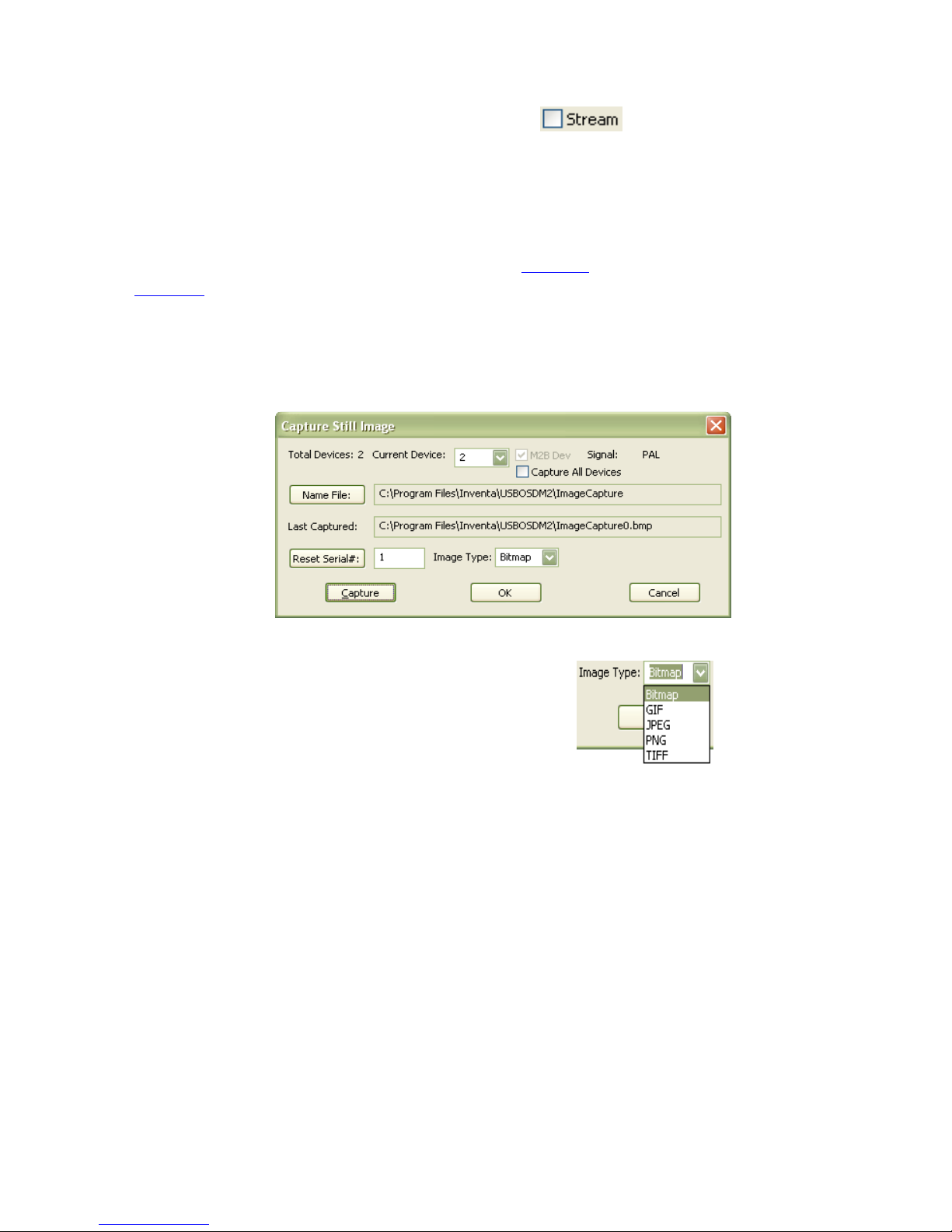
13. Grab Still Image
Still image grabbing creates graphics file from the current video frame. The Capture Still Image setup
window can be brought up from either Drop-down Menu->Image Setup or from Control Window-
>Setup->Image Setup:
In this window, “Name File” defines folder and file names for the still image, “Reset Serial#” set up a
new number to be the next serial number appended to the newly created still image file’s name.
Graphics File type is defined by the Image Type combo box: . If multiple
USBOSDM2 devices are present and “Capture All Devices” box is ticked, clicking the Capture button
will simultaneously capture still images on all devices, otherwise one single image will be captured for
the current device.
To capture still image on one device, Drop-down Menu->Capture Image selection can also be used.
14. Other Drop-down Menu Selections
Show Rec. Status: Enable recording status display inside each USBOSDM2 device’s video
frame within the Video Window.
Maximize Device # Video: This only appears when multiple USBOSDM2 devices are present
-- selecting this item will display the number ‘#’ device’s video in full screen, same as doubleclicking number ‘#’ device’s video area inside the Video Window with Ctrl key pressed.
Maximize: Display the Video Window as Full Screen (same as left mouse double-clicking in
the Video Window without holding down Ctrl key). To restore back to normal window mode,
left mouse double-click again or press Space Bar.
USBOSDM2 Ver. 1.0.0 Page 23 Application Software User Manual
Minimize: Reduce the entire program into an icon on Window’s Task Bar: . To restore
back to normal window mode, left mouse click the icon on the Task Bar.
Mute Speakers: Mute PC speakers for a USBOSDM2 device, will not affect audio in recording.
Exit Program: Quit USBOSDM2 application software.
15. Use Multiple Devices
When multiple (2~8) USBOSDM2 devices are connected to one PC, their video frames will all be
displayed inside the same Video Window: all devices’ video frames are horizontally arranged from left
to right with equal width. When one device’s video frame area is right-mouse single-clicked, the Drop-
down Menu will reflect that device’s current status: if it is recording, if recording is paused, etc. When
operation such as Start Recording, Capture Image, etc. are selected from the Drop-down Menu, only
that device will start the selected operation.
To start/pause/resume/stop recording or streaming simultaneously on more than one devices, use the
menu items under the Record/Stream Menu on the Control Window.
With multiple devices connected, double-clicking left mouse for Full Screen will have two results: if
the Ctrl Key is pressed when double clicking one device’s video frame area inside the Video Window,
this USBOSDM2 device’s video frame will occupy the entire PC screen; if the Ctrl Key is NOT
pressed when double clicking anywhere inside the Video Window, the PC screen will be filled with
Video Window’s content: all devices’ video frames with equal width from left to right.
Please Note: multiple USBOSDM2 devices can consume PC’s CPU usage quickly: avoid using too
many USBOSDM2 devices simultaneously if your PC’s CPU usage reaches 100%.
16. Command Line Parameters
At start up, USBOSDM2 application software accepts some command-line-parameters so that it can
enter certain operation mode once started. Command-line-parameters are supplied in the form of:
–Cmd devNum Value
Where Cmd is a single letter (case sensitive) command, this field must always be supplied;
devNum is the numerical device number(0 for first device), this field must always be supplied;
Value is the value needed for Cmd, this is an optional field depending on Cmd’s content.
Currently supported Command-line-parameters are:

USBOSDM2 Ver. 1.0.0 Page 24 Application Software User Manual
-r devNum: start recording on device “devNum”
-s devNum: start streaming on device “devNum”
-f devNum filename: use filename as recording file name for device “devNum”, note if
filename contains spaces the entire string must be double-quoted
-p devNum pathname: use pathname as recording path name for device “devNum”, note if
pathname contains spaces the entire string must be double-quoted
-t devNum timerVal: use timerVal as recording timer (in Minutes) for device “devNum”
-d: start the program without reading the USBOSDM2.ini file, i.e., use default values for
all parameters (see next section about default parameter values)
-u: start the program in Full Screen mode
-m: start the program in minimized mode
-k: start the program with PC speakers muted for all devices
-x: set the “Rec. Timer Expire Exit Program” option to true
-w: set the “Rec. Timer Expire Shutdown PC” option to true
Some examples:
USBOSDM2.exe –r 0 –f 0 record0.mpg --- start recording on device 1 to file record0.mpg
USBOSDM2.exe –s 0 –d --- start streaming on device 1, do not read USBOSDM2.ini file at start
USBOSDM2.exe –r 0 –r 1 –s 0 –s 1 --- start recording and streaming on device 1 and device 2
USBOSDM2.exe –r 0 –p 0 C:\\dev1 -f 0 rec.mpg --- record on device 1 to file c:\dev1\rec.mpg
USBOSDM2.exe –r 1 –t 1 120 –x --- start recording on device 2 for 2 hours then exit the program
USBOSDM2.exe –r 0 –t 0 60 –w --- start recording on device 1 for 1 hour then shut down the PC
17. Default Parameter Values
USBOSDM2 software uses an initialization file “USBOSDM2.ini” to store values for all of its user-
definable parameters: each time when the software exits, values of these parameters will be saved into
USBOSDM2.ini file which resides in the same folder as the USBOSDM2.exe program file. Each time
when USBOSDM2.exe program starts it uses this file’s contents to assign values to all of its parameters.
If the USBOSDM2.ini file does not exist, or if the Ctrl Key is held down when the USBOSDM2.exe
software is launched, the software will use the following default values for its parameters:
Video Input Channel Parameters:
Channel Window Common Position: 4 Channels (each channel occupies 1/4 of the video frame)
Window Cropping : For PAL: Left=15, Top=10, Width=720, Height=576
For NTSC: Left=15, Top=12, Width=720, Height=480
Disable Video In: No
Input Source: Chan1=Input1, Chan2= Inpu2, Chan3=Input3, Chan4=Input4
Channel Boundary: None
Default Field Rate: 50 Hz
Mirror: No
On Top: Yes
Audio Input Channel Parameters:
Channel Source: Line-in
Mute: No
Left Gain: 70dB
Right Gain: 70dB
Overlay Item Parameters:
Font: Arial Regular 18 Point Yellow
Start X/Y: 0, 0

USBOSDM2 Ver. 1.0.0 Page 25 Application Software User Manual
Use Downloaded Font: No
Download Item on Start: No
Foreground Colour: Yellow
Background Mode: Transparent
Alpha: None
Blink: None
Disable Overlay: No
Timer Format: Time Only
Recording File Parameters:
Recording Path: Same as USBOSDM2.exe file’s path
Recording File Naming Method: Prompt Before Recording
User pre-named Text Recording File Name Field: MPEGRecord
Split Recording File at File Size: 0 (No splitting)
Split Recording File at Record Time: 0 (No splitting)
Split File No. Reset: 0 (No Reset)
Recording Timer: 0 (No Timer)
MPEG Encoding Parameters:
Video Standard: PAL
MPEG Encoding Output Type: DVD Stream
MPEG Encoding Video Output Resolution: 720X576-Pixel PAL, 720X480-Pixel NTSC
MPEG Encoding Video Bit Rate: 8.00 Mbps
MPEG Encoding Bit rate Mode: Constant Bit Rate (CBR)
MPEG Encoding GOP Structure: N==15, M==3
MPEG Encoding Audio Bit Rate: 224 Kbps
MPEG Encoding Audio Sampling Rate: 48KHz
MPEG Encoding Audio Output Mode: Stereo
Video Streaming Parameters:
Streaming Target IP Address: 127.0.0.1
Port Number: 5000
Multicast Streaming: No
Image Grabbing Parameters:
Name File: ImageCapture.bmp in the same folder as USBOSDM2.exe
Serial#: 1
Image Type: Bitmap (.bmp)
Generic Parameters:
PC Speakers Muted: No
PC Speakers Volume: Maximum
Show Rec. Status: Yes
Status Transparent: Yes
Status Start Line: 0
Zoom Video: Disabled
Confirm on Exit: Yes
Rec. Timer Expire Exit Program: No
Rec. Timer Expire Shutdown PC: No
Colour at No-Channel-Area: 0 (Gray)
DirectX Settings Sample Format: InterleavedEven1st
Deinterlace Mode: Mode 1
Colour Bar: Off
SVideo Link: Off
TV2 on YX: Off

USBOSDM2 Ver. 1.0.0 Page 26 Application Software User Manual
18. Menu Hotkeys
For System Menu:
M: Maximize
N: Minimize
X: Exit Program
A: About Dialog
For Setup Menu:
D: Device Setup
C: Channel Setup
I: Image Setup
O: Overlay Setup
R: Record Setup
S: Stream Setup
X: Exit Program
For Record/Stream Menu:
P: Pause Record
R: Start/Stop Record
U: Setup Record
For Drop-down Menu:
A: Capture Still Image
C: Channel Setup
D: Device Setup
E: Start/Resume Recording Video
G: Start/Stop Streaming Video
I: Image Setup
K: Mute PC Speakers
L: Split File for Record
M: Maximize
N: Minimize
O: Overlay Setup
P: Pause Recording
R: Record Setup
S: Stream Setup
T: Stop Record
W: Show Recording Status
X: Exit Program
Z: Maximize Device # Video
19. Technical Discussions
(1) Some PCs’ Screen Saver or Power-Down Screen Settings could cause stopping on live video preview
and record – if this happens, just disable Windows’ Screen Saver / Power-Down Settings.
(2) On Windows 7 and Windows Vista, avoid pressing Ctrl+Alt+Del key-combination since this will stop
video preview and record. Press Ctrl+Shift+Esc key combination instead to start TaskManager.
(3) Windows’ MediaPlayer could fail to play some MPEG1 video files: to replace it use free video players
such as
VideoLan(http://www.videolan.org) or MediaPlayer Classic(http://mpc-hc.sourceforge.net) etc.

USBOSDM2 Ver. 1.0.0 Page 27 Application Software User Manual
(4) Windows’ default “MPEG Audio Decoder” (as part of quartz.dll) can often fail to properly decode
MPEG1 files’ audio: resulting in Windows’ MediaPlayer giving corrupted sound on playing MPEG1 files –
this can be fixed by making MediaPlayer to use a different MPEG Audio Codec Filter, such as the free
“MADFilter.ax” (http://sourceforge.net/projects/maddxshow/) for Windows XP and Vista, or the Microsoft
MPEG-1/DD Audio Decoder Filter “msmpeg2adec.dll” for Windows Vista/7, etc.: after registering these
filters using regsvr32.exe, set their Merit value (using free tools such as RadLight Filter Manager or GSpot
etc.) higher than the Merit value 0x03680001 of the default MPEG Audio Decoder, then reboot Windows.
(5) To use third-party DirectShow-enabled software such as VideoLan( http://ww.videolan.org) etc. to
access the uncompressed analogue video on PC, click the “Disable M2B Device” button on the Device
Setup Window to disable the DirectShow graph built by USBOSDM2 application software. Note in this
application software only one M2B device can be disabled at a time --- USBOSDM2 SDK will be needed
to disable multiple M2B devices and use DirectShow filters: details can be found at the “Using DirectShow
Filters with the SDK” section of the USBOSDM2 SDK User Manual
(http://www.inventa.com.au/Product%20Release%20and%20Comment/USBOSDM2%20SDK%20User%2
0Manual%201.0.0.pdf) .
20. Hardware Specification
Host Interface: 2 X USB2.0 Type B Sockets
Power Supply: through USB Cables
Video Input: 5 X Composite (RCA), 1 X SVideo (4-Pin Mini-DIN)
Video Output (for Real-time Monitoring): 2 X Composite (RCA)
Audio Input: 4 X Line-in 3.5mm Stereo Mini Socket, 2 X Microphone 3.5mm Stereo Mini Jack
Audio Output: 2 X Line-out 3.5mm Stereo Mini Socket
Encoded Video Formats: MPEG2, MPEG1 MP@ML, Program Stream / System Stream
Constant Bit Rate (CBR) and Variable Bit Rate (VBR) Encoding
Video 4:2:2 to 4:2:0 Conversion
Video Inverse telecine (3:2 pulldown)
Video Encoding Frame Rates: 25 fps, 29.95 fps
Video Encoding Bit Rates: 1.00 Mbps ~ 25.00 Mbps
Video Encoding Resolution in Pixels: PAL: 352X288,480X576,720X576,
NTSC: 352X240,480X480,720X480
Video Encoding Aspect Ratio: 4:3
Audio Encoding Format: MPEG1 Layer 2
Audio Sampling Rates: 32KHz, 44.1KHz, 48Khz
Audio Encoding Bit Rates: 192Kbps, 224Kbps, 256Kbps, 320Kbps, 384Kbps
Device Dimension: Top Width 138mm, Bottom Width 168mm, Depth 120mm, Height 40mm
 Loading...