

Inven Sense AN-000013, EV_INMP404-FX, EV_INMP405-FX, EV_INMP504-FX, EV_INMP510-FX User Manual
...
AN-000013
InvenSense Inc.
Wire
Microphone
Red
VDD
Power Supply. 1.5 V DC to 3.6 V DC;
White
OUTPUT
Analog Output Signal
Black
GND
Ground
Maximum
Maximum
INMP404
250 µA
0.18 V rms
200 Ω
0.8 V
INMP405
250 µA
0.18 V rms
200 Ω
0.8 V
INMP504
225 µA
0.18 V rms
200 Ω
0.8 V
INMP510
250 µA
0.40 V rms
350 Ω
0.7 V
ICS-40310
25 µA
0.12 V rms
4.5 kΩ
0.57 V
ICS-40212
165 µA
0.63 V rms
190 Ω
1.0 V
V
DD
0.1µF
OUTPUT
GND
MICROPHONE
Analog Output MEMS Microphone Flex Evaluation Board User Guide
GENERAL DESCRIPTION
This user guide applies to the following MEMS microphone
evaluation boards:
• EV_INMP404-FX
• EV_INMP405-FX
• EV_INMP504-FX
• EV_INMP510-FX
• EV_ICS-40180-FX
• EV_ICS-40181-FX
• EV_ICS-40310-FX
• EV_ICS-40212-FX
TABLE 2. MICROPHONE FUNCTIONAL
DIFFERENCES
Microphone
Supply
Current
Output
Voltage
Output
Impedance
DC
Offset
This is a simple evaluation board that allows quick evaluation
of the performance of single-ended analog MEMS
microphones. The small size and low profile of the flexible
PCB enables direct placement of the microphone into a
prototype or an existing design for an in situ evaluation. The
evaluation board consists of a bottom port microphone
soldered to a flexible PCB with color-coded wires attached.
The only other component on the board is a 0.1 μF supply
bypass capacitor.
Table 1 describes the functions of the three connection wires.
Table 2 describes the functional differences between the
different microphones that are used with this flex circuit.
TABLE 1. PIN FUNCTION DESCRIPTIONS
Color
Pin Description
(0.9 V DC to 1.3 V DC for ICS-40310)
ICS-40180 260 µA 0.40 V rms 350 Ω 0.7 V
ICS-40181 250 µA 0.40 V rms 350 Ω 0.7 V
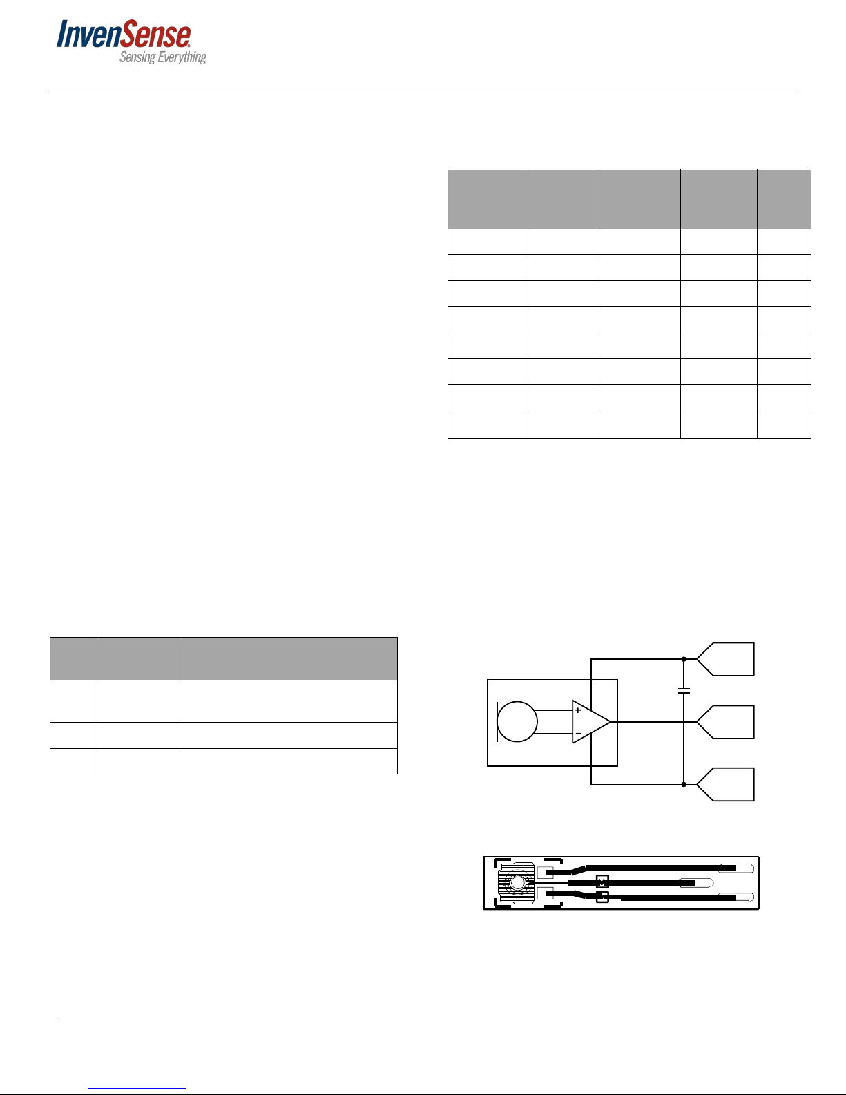
EVALUATION BOARD CIRCUIT
Figure 1 shows the schematic of the evaluation board, and
Figure 2 shows the flex board layout. See the respective
microphone data sheets for complete descriptions and
specifications of the microphones. Note that the layout for
the EV_ICS-40181-FX differs slightly from what is shown in
Figure 2 because of this part’s different package footprint,
but the routing of the three signals is consistent.
InvenSense reserves the right to change the detail
specificatio ns as may be required to permit
improvements in the design of its products.
1745 Technology Drive, San Jose, CA 95110 U.S.A
+1(408) 988–7339
www.invensense.com
Figure 1. Evaluation Board Schematic
Figure 2. Evaluation Board Layout (Top View)
Document Num ber: AN-000013
Revision: 1.5
Release Date: 06/12/2017
AN-000013
3.14mm
15mm
Figure 3. Evaluation Board Dimensions in Millimeters (Wires Not
Included)
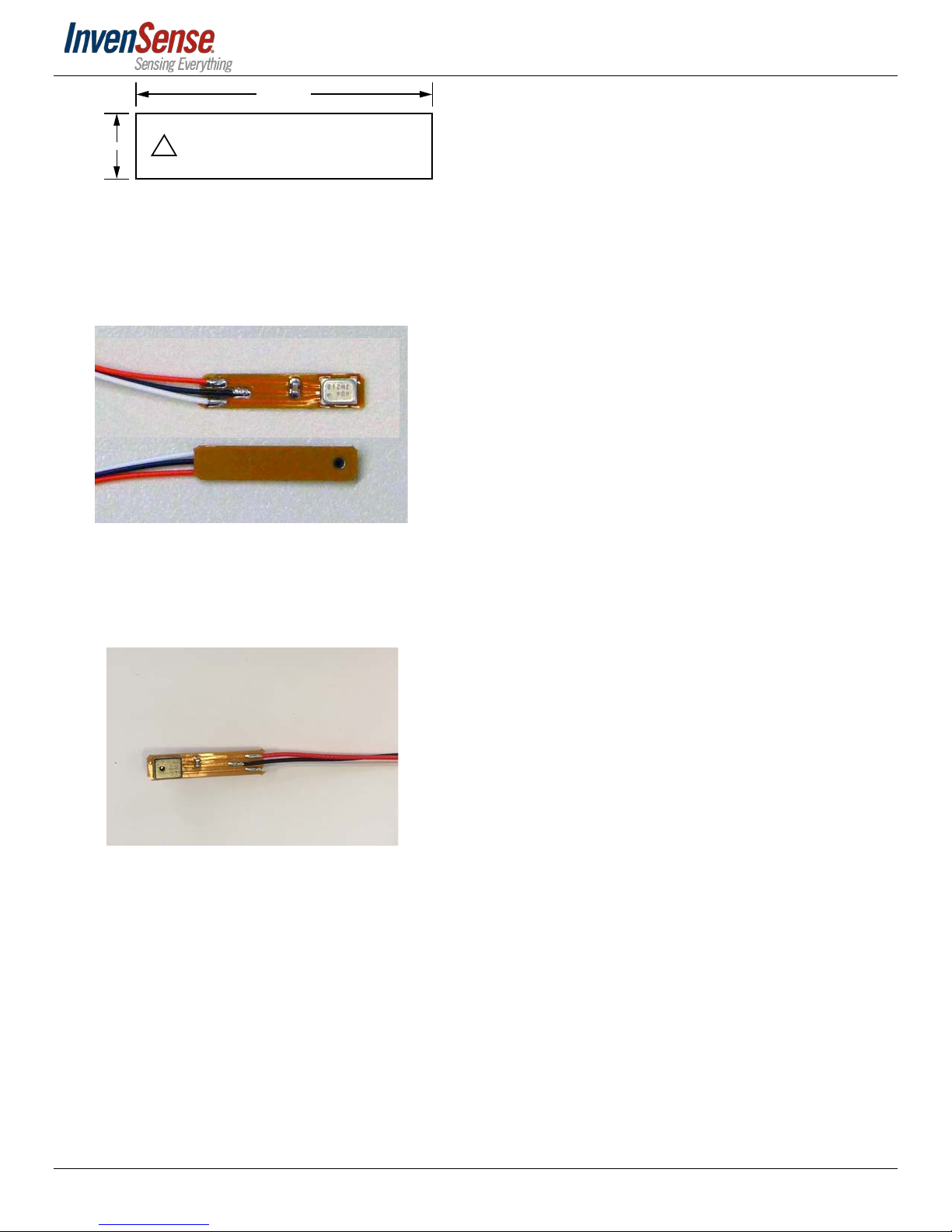
BOTTOM PORT EVALUATION BOARD
PHOTOGRAPH
Figure 4. Top and Bottom View
TOP PORT EVALUATION BOARD PHOTOGRAPH
Figure 5. Top View
Document Number: AN-00 0013
Revision: 1.5
Page 2 of 4

AN-000013
REVISION HISTORY
REVISION
DATE
10/14/2015 1.3 This v1.3 is the initial release in Agile. Previous revisions were uncontrolled.
03/26/2015 1.4 Updated part names, added Figure 5
06/12/2017 1.5 Updated part names
REVISION DESCRIPTION
Document Num ber: AN-000013
Revision: 1.5
Page 3 of 4

AN-000013
COMPLIANCE DECLARATION DISCLAIMER
InvenSense believes the environmental and other compliance information given in this document to be correct but cannot
guarantee accuracy or completeness. Conformity documents substantiating the specifications and component characteristics are on
file. InvenSense subcontracts manufacturing and the information contained herein is based on data received from vendors and
suppliers, which has not been validated by InvenSense.
This information furnished by InvenSense, Inc. (“InvenSense”) is believed to be accurate and reliable. However, no responsibility is assumed by InvenSense for its use,
or for any infringements of patents or other rights of third parties that may result from its use. Specifications are subject to change without notice. InvenSense
reserves the right to make changes to this product, including its circuits and software, in order to improve its design and/or performance, without prior notice.
InvenSense makes no warranties, neither expressed nor implied, regarding the information and specifications contained in this document. InvenSense assumes no
responsibility for any claims or damages arising from information contained in this document, or from the use of products and services detailed therein. This includes,
but is not limited to, claims or damages based on the infringement of patents, copyrights, mask work and/or other intellectual property rights.
Certain intellectual property owned by InvenSense and described in this document is patent protected. No license is granted by implication or otherwise under any
patent or patent rights of InvenSense. This publication supersedes and replaces all information previously supplied. Trademarks that are registered trademarks are
the property of their respective companies. InvenSense sensors should not be used or sold in the development, storage, production or utilization of any conventional
or mass-destructive weapons or for any other weapons or life threatening applications, as well as in any other life critical applications such as medical equipment,
transportation, aerospace and nuclear instruments, undersea equipment, power plant equipment, disaster prevention and crime prevention equipment.
©2017 InvenSense. All rights reserved. InvenSense, MotionTracking, MotionProcessing, MotionProcessor, MotionFusion, MotionApps, DMP, AAR, and the InvenSense
logo are trademarks of InvenSense, Inc.
Document Num ber: AN-000013
Revision: 1.5
©2017 InvenSense. All rights reserved.
Page 4 of 4
 Loading...