

Page 1

User’s Manual
XC2600 Handheld Reader
Invengo Information Technology Co., Ltd.
Page 2
Welcome to be a user of the Invengo RFID products.
We appreciate that you choose the XC2600 handheld reader, hope our
devices will facilitate your experience!
Page 3
Foreword
XC2600 Handheld Reader
This manual provides information on product application, maintenance,
repair and other features for users and maintenance personnel of the
products.
All introduction and descriptions written in this manual, in respect of
the product’s features, functions and other relevant information, are the
latest. All information provided is accurate during the time of printing.
The company retains all rights to make any correction or amendment
to this manual without prior notice and shall bear no responsibility for
these actions.
Some of the product functions may vary due to different conguration
upon special requests from client.
Safety Instructions
Warning sign
If operate improperly, it may result in damage to your equipment(s).
Attention
If ignored, it may result in unsuccessful operation
If ignored, it may cause undesirable effect
Page 4

Content
1. Product overview.........................................................................1
1.1 Product introduction ......................................................................................... 1
1.1 Introduction to XC2600 ..................................................................................... 1
1.2 Main usage and applications............................................................................ 1
1.3 Operating conditions ........................................................................................ 2
1.4 Safety and protective measures ...................................................................... 2
2. Performance parameters ............................................................3
2.1 Main functions ................................................................................................... 3
2.2 Technical parameter .......................................................................................... 3
3. Dimension and weight ................................................................6
3.1 Dimension .......................................................................................................... 6
3.1 Weight ................................................................................................................. 6
4. Structural features and functions .............................................. 7
4.1 Appearance description .................................................................................... 7
4.2 Indicator lights ................................................................................................... 9
4.3 Battery installation and removal ...................................................................... 9
4.4 Power button operation .................................................................................. 10
5. Operating mode ......................................................................... 11
5.1 Online mode ......................................................................................................11
5.2 Ofine mode......................................................................................................11
Page 5

6. Demo software functions and settings ...................................13
6.1 Equipment connection .................................................................................... 13
6.2 Instructions on rd function ........................................................................... 14
6.2.1 Start rd ................................................................................................................... 14
6.2.2 Tag reading operation ............................................................................................. 15
6.2.3 Scan settings ........................................................................................................... 17
6.2.4 Power settings .........................................................................................................18
6.2.5 Tag ltering conguration ...................................................................................... 19
6.2.6 Tag searching .......................................................................................................... 19
6.2.7 Session conguration ............................................................................................ 20
6.2.8 Q-value conguration ............................................................................................. 21
6.3 Barcode function operation demonstration .................................................. 21
6.4 Other functions ................................................................................................ 22
6.5 About ................................................................................................................ 23
6.6 Description on api interface program............................................................ 24
7. Routine maintenance, FAQs and troubleshooting ................. 25
7.1 Routine maintenance ...................................................................................... 25
7.2 FAQs and troubleshooting ............................................................................. 26
7.3 RF communication optimization .................................................................... 26
7.3.1 Signal interference .................................................................................................. 27
7.3.2 Signal attenuation/reection .................................................................................. 27
8. Transportation and storage ...................................................... 29
8.1 Transport requirements .................................................................................. 29
8.2 Storage requirements ..................................................................................... 29
9. Packaging and unpacking ........................................................30
Page 6

9.1 Packaging......................................................................................................... 30
9.2 Unpacking ........................................................................................................ 30
10. After-sales ................................................................................ 31
10.1 After-sales service ......................................................................................... 31
10.2 Other matters ................................................................................................. 31
11. Safety instructions .................................................................. 32
Page 7
User Manual
XC2600 Handheld Reader
1
1. Product overview
1. Product overview
1.1 Introduction to XC2600
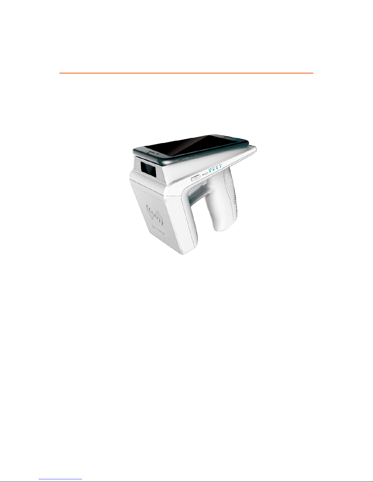
Thank you for using XC2600, our company’s latest model of handheld reader.
XC2600 is legerity in shape, easy to use and suitable for various applications.
XC2600 can coordinate with terminal devices which are equipped with Bluetooth
module. Terminal types such as Android mobile, Android tablet and other types
of equipment can be flexible according to the specific application of choice.
XC2600 supports RFID and barcode functions.
Figure 1 XC2600 Handheld Reader
1.2 Main Usage and Applications
XC2600 has exible usages and can be operated in various elds, such as retail
management, assets management, warehouse management, transportation
management and commodity anti-counterfeiting, etc.
Page 8

User Manual
XC2600 Handheld Reader
2
1.3 Operating Conditions
XC2600 needs the following operating conditions:
Temperature range: -10℃ – 60
℃
Storage temperature: -20℃ - +70
℃
Operating humidity: 5% RH – 95% RH, non-condensing
Storage humidity: 5% RH – 95% RH, non-condensing
1.4 Safety and Protective Measures
Please refer to the following important statement before use!
When this reader is operating (emitting microwave), avoid aiming at human or
livestock for a long time.
Any radio transmitting equipment, including this equipment, may cause
interference with medical equipment that is not properly protected. Should any
problem occur, in respect of the aforementioned, please consult your medical
equipment manufacturer. The operation of this equipment may also cause
interference with other electronic devices.
1. Product overview
Page 9

User Manual
XC2600 Handheld Reader
3
2.Performance Parameters
2.1 Main Functions
Support UHF RFID tags reading and writing operations
Support mainstream 1D, 2D barcode reading( Optional)
2.2 Technical Parameter
Table 2-1 Function parameter
Processor Cortex-M3 processer
Memory Flash:64MBit
EEPROM:256Kbit
Power source Lithium battery:
Standard Removable 5200mAh/3.7 V rechargeable lithium battery
AC input: 100V - 240V/50Hz - 60Hz
DC output: DC5V/2A
Working time: Standby - Not less than 200 hours; operating duration
-not less than 8hrs
Work Status: Real-time monitoring of battery voltage, remaining
battery and charging status
2. Performance parameters
Page 10

User Manual
XC2600 Handheld Reader
4
UHF-RFID
module
Supported protocols: EPC Global UHF Class 1 Gen 2/ISO 18000-
6B/6C
Operating frequency:
840MHz—845MHz(CN2)
920MHz—925MHz (CN1)
865MHz—868MHz (EU)
902MHz—928MHz (FCC)
Output power: 0-30dBm, stepping 3dB
Reading distance:
Tag reading: 0~6m, tag writing: 0~3m (depending on the specic
conguration )
Maximum tag capacity:
Maximum 496 Bits for EPC
Maximum 128 Bits for TID
Maximum 64K Bits for user data
Barcode engine
(Optional)
Support code system:
1D code: Code 128, EAN-13, EAN-8, Code 39, UPC-A, UPC-E,
Codabar, Interleaved 2 of 5, ITF-6, ITF-14, ISBN, Code 93, UCC/
EAN-128, GS1 Databar, Matrix 2 of 5, Code 11, Industrial 2 of 5,
Standard 2 of 5, Plessey, MSI-Plessey, etc.
2D code: PDF417, QR Code, Data Matrix(ECC200,E
CC000,050,080,100,140, etc.)
BT BT2.0
Status indication Lights:
Barcode indicator
RFID module indicator
Bluetooth indicator
System/charge indicator
Buzzer
Sounds indication of equipment operational condition
External ports USB Type-C power port
5V DC power output port(optional, OFF by default)
2. Performance parameters
Page 11

User Manual
XC2600 Handheld Reader
5
Working
environment
Temperature range: -10℃ – +60
℃
Storage temperature: -20℃ - +70
℃
Operating humidity: 5% RH – 95% RH, non-condensing
Storage humidity: 5% RH – 95% RH, non-condensing
Shock resistance: GB/T 2423.10-2008/IEC 60068 -2 -6:1995;
acceleration: 4.9m/s2, Frequency range: 5Hz-100Hz; Drive
amplitude (Peak mm) 25/f(f=5Hz-10Hz), 250/f2(f=10Hz-100Hz)
2. Performance parameters
Page 12
User Manual
XC2600 Handheld Reader
6
3. Dimension and Weight
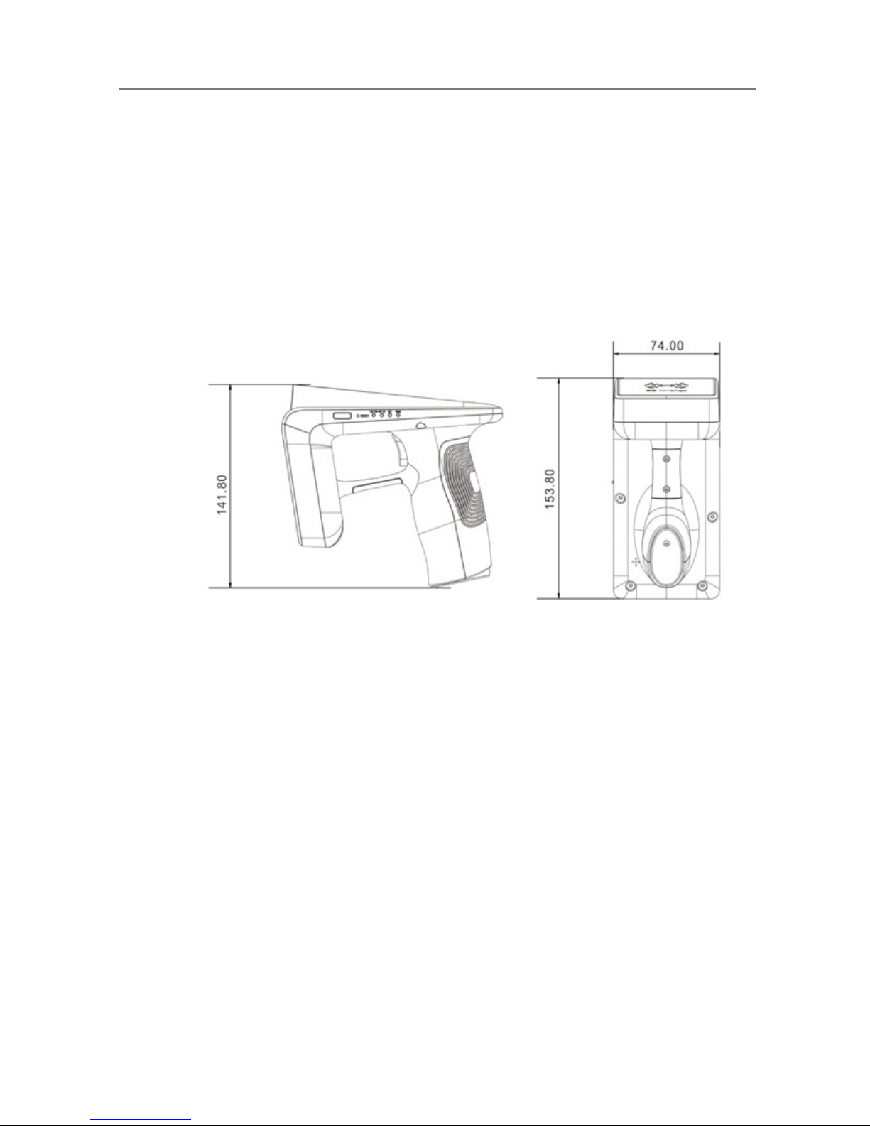
3.1 Dimension
The overall dimension of XC2600 is 153.8mm×141.8mm×74mm, as shown in Figure 2.
Figure 2 XC2600 size illustration
3.2 Weight
The overall weight of XC2600 is 390g. (Include battery and RFID module but
without barcode module).
3. Dimension and Weight
Page 13

User Manual
XC2600 Handheld Reader
7
4. Structural Features and Functions
This chapter describes XC2600’s composition, internal structure, functions and
interface of respective modules in details.
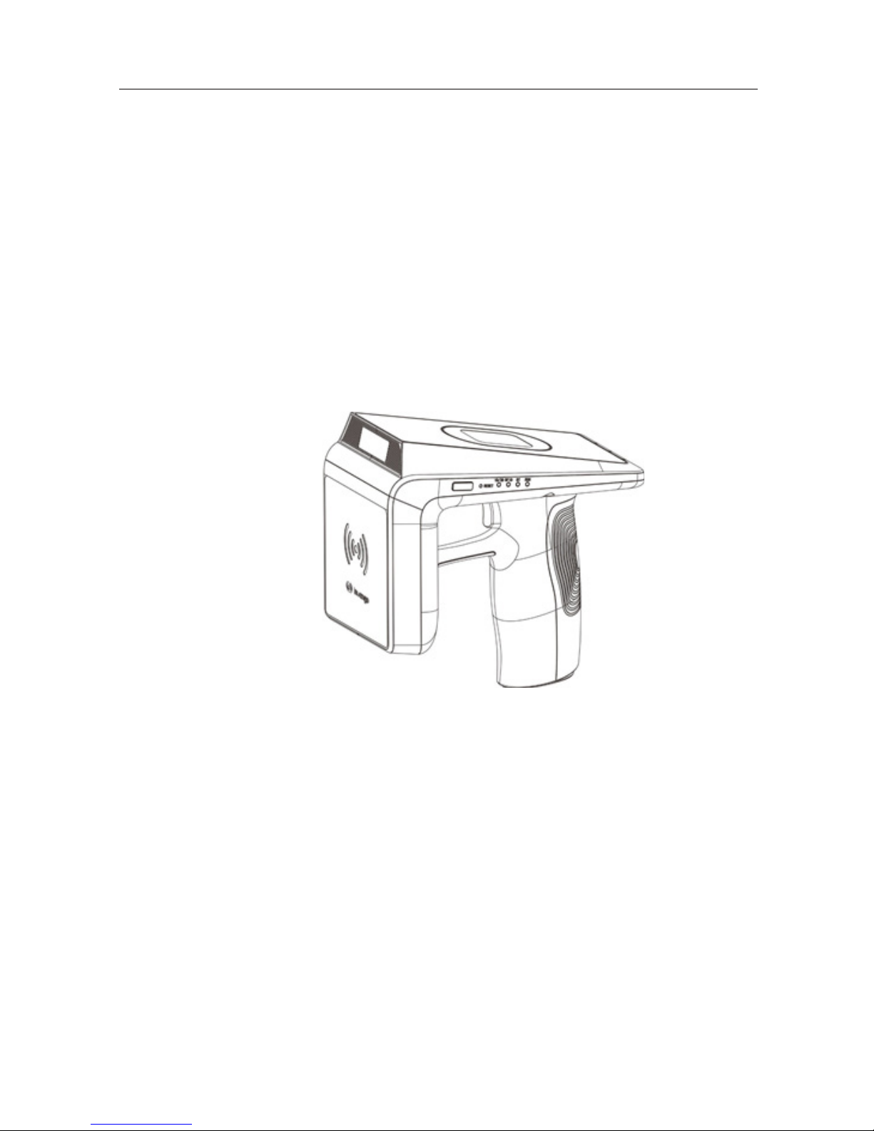
4.1 Appearance Description
Front view of XC2600 is shown in Figure 3, functions of each part are described
as follows.
Figure 3 Front view of the reader
RFID Module
Built-in UHF-RFID module, for more information about band and protocol, see
the Table 1.
Barcode Module(optional)
Optional module; 1D or 2D barcode module can be selected according to
customers’ requirements.
Power Button
Can be used for power button, also can be used as a sleep / wake button. Please
see gure3 for details
Reset Button
Device forced reset button. Please see gure 3 for details
4. Structural Features and Functions
Page 14

User Manual
XC2600 Handheld Reader
8
Magnetic Groove
It is a magnetic groove for smartphone attachment. Take out the sheet iron
included in the package and peel off the liner to reveal the adhesive side of sheet
iron. Attach the adhesive side of sheet iron to the center of the groove, then
attach back of the phone to the groove. Simply remove phone when not in use.
The sheet iron and mobile installations are showed in Figure 4.
Figure 4 mobile phone installations
Function Indicator Lights
Including Barcode, RFID, Bluetooth and system operating indicator lights.
Please see gure 4 for Details
Battery
5200mAh removable battery.
4. Structural Features and Functions
Page 15

User Manual
XC2600 Handheld Reader
9
Trigger
RFID or barcode function button, can also be used as standby/wake-up button.
USB Interface
Including USB Type-C charging and communication interface and USB-A power
output interface.
4.2 Indicator Lights
1D/2D: (blue) The indicator light blinks slowly when barcode module is
activated; when the barcode module turns off the indicator light switches off.
RFID: (blue) The indicator light blinks slowly when RFID module is
activated, when the RFID module turns off the indicator light switches off.
BT: (blue) The indicator light blinks slowly when Bluetooth is successfully
connected; Off when Bluetooth is unconnected.
RUN: (red) The indicator light blinks slowly when system operating normally,
ashes rapidly when malfunction appears, On when device is being charged.
4.3 Battery Installation and Removal
The battery is placed in the package box when device is in transportation. Please
install the battery before use. The following illustration demonstrates the stepby-step installation procedures:
(Simply reserve the installation process to remove battery.)
4. Structural Features and Functions
Page 16

User Manual
XC2600 Handheld Reader
10
Figure 6 Battery installation step
4.4 Power button Operation
Power button operation includes turn on reader, shutdown, standby, wake reader,
restart operation, the specic operation is described as follows:
Turn On Reader
When the device is in off mode, press and hold the power button until the built-
in buzzer beeps and the RUN indicator light blinks which means the equipment
is successfully start operating. Then release the power button.
Turn Off Reader
When the device in working mode, press and hold the power button until the
buzzer beeps, release the power button the system will be shut down completely.
Standby
Briey press the power button to enter the standby mode when the equipment is
operating.
Wake Reader
In standby mode, briey press the power button or pull the trigger, the equipment
will resume and starts operating.
Restart
Softly press the key in the RESET hole with a tool to restart the device.
4. Structural Features and Functions
Page 17

User Manual
XC2600 Handheld Reader
11
5.Operating Mode
This equipment can be paired with other Bluetooth-equipped devices via
Bluetooth. By using other terminal devices installed with demo application of
the XC2600 reader, you can control the device by this Invengo Demo directly.
The device may switch into ofine mode and work independently when loss the
connection with Bluetooth terminal devices temporarily, when the Bluetooth are
successfully connected, the local data can be uploaded to the demo software.
5.1 Online Mode
When the device connects with a Bluetooth terminal, it works in Online working
mode. Under this mode, you can control equipment working mode with Invengo
Demo of the Bluetooth terminal. You can choose mobile phone, tablet computer
and other Bluetooth terminals for operating terminals. The APIs for JAVA
platform are currently available.
For detailed operation, refer to the Invengo Demo operating instructions of
chapter VI.
5.2 Oine Mode
When the Bluetooth connection is not established, it will automatically enter
the ofine mode. Working data can be stored locally in ofine mode. The main
features of ofine working mode are shown as follows:
Module which was working before ofine mode continues
Buzzer works unconditionally
Read data is stored in local memory
You need to set the data saving interval in online mode to ensure the regular
operation of the device. The Flash interval is the time interval that working data
stored in RAM before writing into Flash, set an appropriate time interval to
ensure cached data is not lost. Click “More”, then click “Time Interval”, insert a
value between 1 and 60, then click “Congure”, you may also “Query” current
parameter by clicking “Query”. Please refer to Figure 7 below.
5. OPerating Mode
Page 18

User Manual
XC2600 Handheld Reader
12
Figure 7 Data save interval setting
The data stored in the local Flash can be uploaded to the background system
by connecting to the Bluetooth terminal demo software. Click “More” in the
menu of the demo software, then click “Flash Cache Data”, select “Export” to
download the data cached by the device, as shown in Figure 8.
Figure 8 Flash data upload
5. OPerating Mode
Page 19

User Manual
XC2600 Handheld Reader
13
6.Demo Software Functions and Settings
This equipment can coordinate with Bluetooth terminal, specic functions are
implemented by terminal application software.
6.1 Equipment Connection
Bluetooth pairing is required when devices connect for the first time. After
pairing, use the Demo to set up connection, as shown in Figure 9.
Figure 9 Bluetooth pairing
1) Search for the device you want to connect on a smartphone installed with
Bluetooth. (take XC2600 for example)
2) In the pairing interface, enter the pairing password. The default password is
1234. After pairing, start the Demo software, as shown in Figure 10.
6. Demo Software Functions and Settings
Page 20

User Manual
XC2600 Handheld Reader
14
Figure 10 start Demo
6.2 Instructions on RFID Function
RFID function is mandatory, RFID performance and the practical working
environment is closely related. Label read distance 0 ~ 6M, write distance 0 ~
3m, Actual performance is related to the label and the specic conguration of
the device.
6.2.1 Start RFID
There are two ways to turn on the RFID function, as shown in Figure 11.
6. Demo Software Functions and Settings
Page 21

User Manual
XC2600 Handheld Reader
15
Figure 11 RFID function selection
1) Select RFID when you open the Demo application, click the Connect button,
you can open the RFID.
2) At the status of being connected to 1D, 2D (barcode), click the “Menu”, you
can switch to the RFID channel.
6.2.2 Tag Reading Operation
1) Click the start button on the Invengo Demo or pull the trigger button on the
handle to start reading the tags.
2) Tag reading information is located in the center of the interface. Total number
of tags locates at the bottom, as shown in Figure 12
6. Demo Software Functions and Settings
Page 22

User Manual
XC2600 Handheld Reader
16
Figure 12 RFID tag reading
Click the area of EPC information of tag which needs to be handled to open
the tag operation dialog box, as shown in Figure 13.
Figure 13 Tag information operation
In the tag operation interface, each area of the tag can be read or written, or
implement related conguration.
6. Demo Software Functions and Settings
Page 23

User Manual
XC2600 Handheld Reader
17
6.2.3 Scan Settings
The setting for prompt sounds, RSSI, tag type and tag data areas are shown in
Figure 14.
Figure 14 scan settings
Save
Save the changes.
Prompt Sounds
This setting is for switching on/off of prompt sounds when reading.
RSSI
This setting is for RSSI to be shown or not when reading.
Operation Type
This setting is for reading type, single reading means work once after reading
starts; continuous reading means the reader keep reading once upon it is started.
Tag Types
Set types of tags that you want to read.
TID Reading
Read tags’ TID area only.
6. Demo Software Functions and Settings
Page 24

User Manual
XC2600 Handheld Reader
18
General Reading
Read tags’ EPC, TID, user data area at the same time.
TID Length
Set the TID length of tags that you need to read (settable only in general reading
status).
User Data Initial Address
This is for setting the start address of user data area for tag reading(settable only
in general reading status).
User Data Area Length
This is for setting the length of user data area (settable only in general reading
status).
6.2.4 Power Settings
Query and set query the antenna power, as shown in Figure 15.
Figure 15 Power settings
Conguration: Save the antenna power setting;
Query: Check the antenna power has been set;
Antenna: The power varies according to the hardware.
6. Demo Software Functions and Settings
Page 25

User Manual
XC2600 Handheld Reader
19
6.2.5 Tag Filtering Conguration
This setting is about an interval, once a tag data was uploaded, ltering that tag
within that interval, for more information, see Figure 16.
Figure 16 Tag lter conguration
Conguration: set the saving time interval.
Cancel: cancel the label ltering settings.
Interval Time: Setting for the filter time interval, within this interval a
repeated tag should be ignored.
6.2.6 Tag Searching
Click “Find Tag” in the “More” interface. Enter the “Find Tag” interface, as
shown in Figure 17.
6. Demo Software Functions and Settings
Page 26

User Manual
XC2600 Handheld Reader
20
Figure 17 Tag Searching
Set the conditions of tag searching, you can “Find” search relevant tags.
6.2.7 Session Conguration
Session configuration parameters will affect single tag or multi-tag reading
efficiency, generally can be set in multi-tag read mode. Enter the “More”
interface and select “Session Conguration” to enter the session conguration
interface, as shown in Figure 18
Figure 18 session conguration
6. Demo Software Functions and Settings
Page 27

User Manual
XC2600 Handheld Reader
21
After setting the type of session conguration S0,S1,S2,S3 and session mark
click “Configure” to take effect, or you can “query” current configuration
parameters.
6.2.8 Q-value Conguration
The Q-value will affect the performance of multi-tag reading. The maximum
of tag number which can be read is 2Q-1, and for multi-tag reading, the
recommended Q-value is 4. Click “Q-value Conguration” in “More” interface,
as shown in Figure 19:
Figure 19 Q-value conguration
6.3 Barcode Function Operation Demonstration
1D and 2D barcode (compatible with the identification of 1D barcode) are
optional congurations and can be added on demand, the main support barcode
system are:
1D code: Code 128, EAN-13, EAN-8, Code 39, UPC-A, UPC-E, Codabar,
Interleaved 2 of 5, ITF-6, ITF-14, ISBN, Code 93, UCC/EAN-128, GS1 Databar,
Matrix 2 of 5, Code 11, Industrial 2 of 5, Standard 2 of 5, Plessey, MSI-Plessey.
2D code: PDF417, Data Matrix (ECC200, ECC000, 050, 080, 100, 140), QR
Code.
6. Demo Software Functions and Settings
Page 28

User Manual
XC2600 Handheld Reader
22
There are two ways to turn on the barcode function, as shown in Figure 20:
Select “1D2D” in the interface, click “Connect”, you can review the barcode function.
Under the RFID mode, click the menu to switch to the barcode channel.
Figure 20 barcode function selection
6.4 Other Functions
Enter “More” interface, you can set other relevant information.
Restart/Reset
Restart: restart the handheld reader, Reset: return XC2600 settings to their
defaults.
Standby Time
Time interval that device enter standby mode without being operated,
congurable range: 30 ~ 600s; The device automatically enters standby mode
when exceed the set time.
Flash Time Interval
Flash Time Interval is the time interval that data is written to Flash under the
ofine mode, congurable time within 60s.
6. Demo Software Functions and Settings
Page 29

User Manual
XC2600 Handheld Reader
23
Clock Synchronization
After the device connects to a Bluetooth terminal device, you can manually
synchronize the local time.
Buzzer Conguration
Select whether the buzzer function is enabled when the device is under online
mode
Flash Cache
Export data that cached in Flash in ofine mode.
USB Power Supply Control
The switch for USB-A port and 5V power supply.
UTC Switch
Turn on the clock display switch during card reading operation.
6.5 About
This chapter describes the software and hardware version of the device, as shown
in Figure 21.
Figure 21 version information
6. Demo Software Functions and Settings
Page 30

User Manual
XC2600 Handheld Reader
24
Application Information: Application Version Information.
System Information: Bluetooth terminal system version.
RFID information: Relevant information about software and hardware
version of the RFID module.
ARM information: XC2600 baseband software version information.
For the functional introduction and application development issues of
the DEMO program, please refer to the corresponding directory under
“RFID Handheld Universal Demo Software User Manual” in the CD
provided.
6.6 Description on API interface program
API interface program is the intermediary between XC2600 and background
applications, providing the users with the software interface for secondary
development.
For the application of API interface program and development issue
pertaining to the application software, please refer to the corresponding
directory under “Reader’s Generic API Technical Reference Manual” in
the CD provided.
6. Demo Software Functions and Settings
Page 31

User Manual
XC2600 Handheld Reader
25
7.Routine Maintenance, FAQs and Troubleshooting
7.1 Routine Maintenance
Store the device in a cool and dry place, with temperature ranged between
+10℃- +40℃. Avoid contact with corrosive substances and keep away from re
and heat sources (For details please refer to 8.2 storage requirement).
Due to the self-discharging characteristics of lithium battery, if the device
is not being in use for a long period of time (not less than 1 month), it
is recommended that the battery should be removed from the handheld
device and stored separately (Battery capacity is best for long term
storage at 40%, and should be fully charged and left discharged every
three months, if possible).
Precautions for battery usage:
Do not directly connect the input to output terminal;
Do not expose the battery to water or get it wet;
Do not use or store the battery near a heat source (such as re or heater);
Please use original charger;
Do not reverse the positive and negative;
Do not plug the battery directly in a wall outlet or car cigarette lighter socket;
Do not put the battery into a re or heat up the battery;
Do not use wire or other metal to connect the positive and negative terminals
of the battery, do not transport or store the battery with necklace, hairpins or
other metallic objects;
Do not disassemble the battery or cause battery short circuit;
Do not cause impact to the battery or use sharp object to hit the battery.
7. Routine Maintenance, FAQs and Troubleshooting
Page 32

User Manual
XC2600 Handheld Reader
26
7.2 FAQs and Troubleshooting
This section introduces solutions to some of the common problems or
irregularities during the usage of the device.
Unable to Read Tags
Initially, please check whether the tag samples are functioning, or use another
tags which has been veried for further test;
Please conrm if the electronic tag is within the effective range of reader;
Please conrm if there is any RF signal interference.
Unable to Wright Tags
Initially, please conrm if the tag is writable.
Please conrm if the electronic tag is within the effective range of the reader;
Please conrm if the data area of the electronic tag has been locked;
Please conrm if the instruction parameter is congured correctly;
Please conrm if there is any RF signal interference.
Why is the tag writing distance closer than data reading distance?
This is due to the special characteristics of RFID technology. Tag writing
requires more energy than tag reading, hence the distance is shorter and success
rate of tag writing is much lower as compared to tag reading.
Why do the reading distances for various tags appear to be so different?
This is due to the special characteristics of RFID technology. Different tag chip
and their sealing materials have different sensitivity towards the reader; hence
the operating distance and success rate are different.
7.3 RF Communication Optimization
Under normal circumstances, radio technology is used for device communication.
The system performance is very sensitive towards signal interference and
attenuation. This section provides some tips for radio communication
optimization between XC2600 and electronic tags.
7. Routine Maintenance, FAQs and Troubleshooting
Page 33

User Manual
XC2600 Handheld Reader
27
7.3.1 Signal Interference
Signal interference refers to the radio frequency (RF) signal that caused
interference to the data exchange between the handheld reader and electronic
tag. Signal interference can severely affect the capability of a handheld reader to
retrieve information from an electronic tag.
Sources of signal interference:
Radio frequency (RF) system, such as RF local area network and nearby
interactive identication system;
RF signals from security doors, garage doors or other devices;
Other RF radiation sources.
When there is radio frequency (RF) interference or noise, the performance of
handheld reader (with regard to its data exchange with electronic tag) will be
reduced signicantly. Handheld reader can only “accept” one signal at any given
time, and it is not capable to distinguish between undesirable noise and useful
RF signals
7.3.2 Signal Attenuation/Reection
Signal attenuation refers to the natural attenuation of signal strength, resulted
from the distance. It may be due to the obstacle encountered in its transmission
path.
Possible obstacles for radio frequency signal:
Enclosed space with concrete walls, oors and ceilings;
Metallic surface surrounding antenna or tag;
Water or other liquid surrounding antenna or tag.
Almost every object (including furniture or partition) will cause a different
degree of attenuation during transmission process. This attenuation resulted from
obstacle can be reduced to the lowest degree through careful repositioning of
antenna installation position.
At the same time, the reflection caused by metal or metalized surface on the
back of the electronic tag may also contribute to signal attenuation. Under some
circumstances, this causes slight increase in reading distance and results in blind
corners. At these blind corners, the communication between the electronic tag
and handheld reader is very poor.
Generally, it is impossible to conduct accurate prediction of the handheld reader
system’s performance under any given environment (this is due to the complexity
7. Routine Maintenance, FAQs and Troubleshooting
Page 34

User Manual
XC2600 Handheld Reader
28
of electromagnetic radiation, including stability of frequency of signal source,
antenna pattern, antenna sidelobe, and the surrounding environment). However,
some of the recommendations given below can provide a certain degree of
guidance in the specic environment, as well as application in optimizing system
performance:
Take into account the radio frequency (RF) characteristic in the surrounding area,
including building materials, office hour, windows, and piping configuration.
Radio frequency (RF) eld mode and reading distance may be affected by metal
objects nearby, such as household appliances, equipment and metal frames.;
The electronic tag must remain in the effective reading area of the handheld
reader for not less than 100ms (for XC-TF8030-B-C07 electronic tags);
The optimal antenna length for electronic tag is related to the non-conductive
materials sealed or embedded with the tag. Here is the basic concept: For
electronic tag embedded within non-conductive materials (The dielectric
constant is generally larger than the dielectric constant in the air, causing the
effective wavelength of the medium to be shorter than the wavelength of the air)
or placed in substrate, if its effective wavelength has been adjusted to the optimal
length in open space (at the furthest reading distance from the handheld reader),
the electric length of the tag antenna must be reduced to achieve the best effect
in open space. On the contrary, if the effective wavelength has been adjusted to
the optimal length within non-conductive materials, the electrical length of the
tag antenna must be increased to achieve the best effect in open space.
Do not expose naked, unsealed electronic tag with chemicals. Certain chemicals,
such as alcohol, can be corrosive under high temperature, even though they are
safe under normal temperature.
7. Routine Maintenance, FAQs and Troubleshooting
Page 35

User Manual
XC2600 Handheld Reader
29
8.Transportation and Storage
8.1 Transport Requirements
XC2600 meets all the standard requirements of road, rail, air, and water
transportations.
8.2 Storage Requirements
The long term storage of XC2600 must meet the following conditions:
Ambient temperature: -10℃ - +40℃;
Relative humidity: less than 80%;
No abrupt temperature change, with the absence of acidic gas and other harmful
gases;
Due to the self-discharging characteristics of lithium battery, if the device is not
in use for a long period of time (not less than 1 month), it is recommended that
the battery should be removed from the handheld device and stored separately.
8. Transportation and Storage
Page 36

User Manual
XC2600 Handheld Reader
30
9.Packaging and Unpacking
9.1 Packaging
XC2600 is packed in a box, and transported through large transport container.
9.2 Unpacking
In order to facilitate future storage and transport, keep the box and packaging
materials when you unpack the product packaging.
Please check the product and its accessories according to the packing
list. Please contact us immediately if there is any discrepancy or damage.
9. Packaging and Unpacking
Page 37

User Manual
XC2600 Handheld Reader
31
10.After-sales
10.1 After-sales Service
If you encounter any unsolvable problem when using our product, please contact
the customer service center.
Before a user engages our customer service center, please prepare the following
information at hand:
Handheld reader model
Handheld reader serial number (Located at the bottom of a handheld reader)
Any changes to the handheld reader or tag
Application software’s status and condition Handheld reader model
10.2 Other Matters
If our customer service officer has confirmed with the user to return his/her
handheld reader for maintenance, the user will receive a return merchandise
authorization (RMA) from our customer service ofcer. Please indicate the RMA
no. on the exterior of the return product packaging and, at the same time, provide
the same no. on a piece of paper and place it inside the packaging. This will
ensure the quick processing of the return product.
Please follow these steps when returning the handheld reader for maintenance:
Carefully pack the handheld reader and its accessories into the original
antistatic foam box. Please use a box with protective effect if the original box no
longer exists.
Use ller to cover the products in the box.
Place a note, written with RMA no., in the box.
Indicate RMA no. and the word “fragile” on the exterior of the box.
10. After-sales
Page 38

11.Safety Instructions
Warning Sign
Improper operation may cause the damage to the device.
Attention Sign
If ignored, your operation might not work well.
If ignored, might cause results beyond anticipation.
11.Safety Instructions
Page 39

FCC RF Exposure Information and Statement
The XC2600 Handheld Reader( model:XC2600)has been tested for body Specific Absorption Rate
(SAR) compliance. The radio module has been evaluated under KDB 865664 D01 and found to be compliant
to the requirements as set forth in CFR 47 Sections, 2.1093, and 15.247 (b) (4) addressing RF Exposure from
radio frequency devices. This model meets the applicable government requirements for exposure to radio
frequency waves. The highest SAR level measured for this device was 0.41 W/kg.
FCC Warning
This device complies with Part 15 of the FCC Rules. Operation is subject to the following two conditions:
(1) This device may not cause harmful interference, and (2) this device must accept any interference received,
including interference that may cause undesired operation.
NOTE 1: This equipment has been tested and found to comply with the limits for a Class B digital device,
pursuant to part 15 of the FCC Rules. These limits are designed to provide reasonable protection against
harmful interference in a residential installation. This equipment generates, uses and can radiate radio frequency
energy and, if not installed and used in accordance with the instructions, may cause harmful interference to
radio communications. However, there is no guarantee that interference will not occur in a particular
installation. If this equipment does cause harmful interference to radio or television reception, which can be
determined by turning the equipment off and on, the user is encouraged to try to correct the interference by one
or more of the following
measures:
- Reorient or relocate the receiving antenna.
- Increase the separation between the equipment and receiver.
- Connect the equipment into an outlet on a circuit different from that to which the receiver is
connected.
- Consult the dealer or an experienced radio/TV technician for help.
NOTE : Any changes or modifications to this unit not expressly approved by the party responsible for
compliance could void the user's authority to operate the equipment.
Page 40

Shenzhen HQ:
Corporate Headquarters
Invengo Information Technology Co., Ltd.
3/F, No.T2-B, High-tech Industrial Park South,
Shenzhen 518057, China
Tel: +86 800 830 7036
Fax: +86 755 2671 1693
Email: sales@invengo.cn
Website: www.invengo.cn
Singapore:
Invengo Technology Pte. Ltd.
10 Kallang Avenue, # 05-15 Aperia tower 2,
Singapore, 339510
Tel:+65 6702 3909
Email: invengo.sales@invengo.sg
Website: www.invengo.sg
US:
Invengo Technology Corp
2700-160 Sumner Blvd.
Raleigh, NC 27616, USA
Tel: +1 919 890 0202
Toll Free: +1 855 379 2725
Email: sales@invengo.com
Website: www.invengo.com
Europe:
Invengo Technology BV
Belder 30-A, 4704RK Roosendaal,
The Netherlands
Tel: +31 88 6363 793
Fax: +31 88 6363 794
Email: web@invengo.eu
Korea:
Invengo International Pte. Ltd (Korea)
30F ASEM Tower, 517 Yeongdong-daero,
Gangnam-gu, Seoul 135-798 Korea
Tel: +82 2 6001 3525
Fax: +82 2 6001 3003
Email: justin.kou@invengo.sg
 Loading...