

Page 1

G7OPT Integrator Manual
DWI-00175 S1 R15
Dec 05, 2016
S1 Security Level Guide
Contains sensitive information.
Do not supply to any party outside of Invenco without authority from the management team.
Document must only be distributed under Non-Disclosure Agreement (NDA).
Page 2

Contents
1 Introduction 1
1.1 Important Related Documents . . . . . . . . . . . . . . . . . . . . . . . . . . . . . . . . . . 1
1.2 Important Information on Radio Frequency Components . . . . . . . . . . . . . . . . . . . 1
1.2.1 FCC Compliance Statements . . . . . . . . . . . . . . . . . . . . . . . . . . . . . . 1
1.2.2 Industry Canada Compliance Statements . . . . . . . . . . . . . . . . . . . . . . . 2
2 Shipment Verification 3
2.1 Introduction . . . . . . . . . . . . . . . . . . . . . . . . . . . . . . . . . . . . . . . . . . . . 3
2.2 Shipment Checks . . . . . . . . . . . . . . . . . . . . . . . . . . . . . . . . . . . . . . . . . 4
2.2.1 Bulk Packaging Check . . . . . . . . . . . . . . . . . . . . . . . . . . . . . . . . . . 4
2.2.2 Serial-number Check . . . . . . . . . . . . . . . . . . . . . . . . . . . . . . . . . . . 4
2.2.3 Individual Box Checks . . . . . . . . . . . . . . . . . . . . . . . . . . . . . . . . . . 4
2.3 Integrity Verification . . . . . . . . . . . . . . . . . . . . . . . . . . . . . . . . . . . . . . . . 6
2.3.1 Initial Power-on Check . . . . . . . . . . . . . . . . . . . . . . . . . . . . . . . . . . 6
2.3.1.1 Tamper Indications . . . . . . . . . . . . . . . . . . . . . . . . . . . . . . . 6
2.3.2 Hardware Certification Status . . . . . . . . . . . . . . . . . . . . . . . . . . . . . . 7
2.4 Version Verification . . . . . . . . . . . . . . . . . . . . . . . . . . . . . . . . . . . . . . . . 9
2.4.1 Hardware Certification Revision . . . . . . . . . . . . . . . . . . . . . . . . . . . . . 9
2.4.2 Software Version Numbers . . . . . . . . . . . . . . . . . . . . . . . . . . . . . . . 10
2.5 Communications . . . . . . . . . . . . . . . . . . . . . . . . . . . . . . . . . . . . . . . . . . 12
2.5.1 Receipt Verification . . . . . . . . . . . . . . . . . . . . . . . . . . . . . . . . . . . . 12
2.5.2 Exception Escalation . . . . . . . . . . . . . . . . . . . . . . . . . . . . . . . . . . . 12
3 Tampers 13
3.1 Background – Tamper Types . . . . . . . . . . . . . . . . . . . . . . . . . . . . . . . . . . . 13
3.1.1 Tamper Indications . . . . . . . . . . . . . . . . . . . . . . . . . . . . . . . . . . . . 13
3.2 Removal Tampers . . . . . . . . . . . . . . . . . . . . . . . . . . . . . . . . . . . . . . . . . 14
3.2.1 Installation with Removal-Tamper Sensors . . . . . . . . . . . . . . . . . . . . . . . 15
3.2.2 Removal-Tamper Clearing and Promotion to Normal Operation . . . . . . . . . . . 15
3.3 Retrieving logs and exporting parameters . . . . . . . . . . . . . . . . . . . . . . . . . . . . 17
4 Key Injection 19
4.1 Background . . . . . . . . . . . . . . . . . . . . . . . . . . . . . . . . . . . . . . . . . . . . 19
4.2 Terminology . . . . . . . . . . . . . . . . . . . . . . . . . . . . . . . . . . . . . . . . . . . . 19
4.3 Installation . . . . . . . . . . . . . . . . . . . . . . . . . . . . . . . . . . . . . . . . . . . . . 19
4.4 Swap-outs . . . . . . . . . . . . . . . . . . . . . . . . . . . . . . . . . . . . . . . . . . . . . 19
5 Appendices 20
5.1 G7SDC Installation Guide . . . . . . . . . . . . . . . . . . . . . . . . . . . . . . . . . . . . 20
5.1.1 Introduction . . . . . . . . . . . . . . . . . . . . . . . . . . . . . . . . . . . . . . . . 20
5.1.2 Installation . . . . . . . . . . . . . . . . . . . . . . . . . . . . . . . . . . . . . . . . . 21
5.1.2.1 Environment . . . . . . . . . . . . . . . . . . . . . . . . . . . . . . . . . . . 21
5.1.2.2 Tools . . . . . . . . . . . . . . . . . . . . . . . . . . . . . . . . . . . . . . . 21
DWI-00175 S1 R15 i
Page 3

5.1.2.3 Method . . . . . . . . . . . . . . . . . . . . . . . . . . . . . . . . . . . . . . 21
5.1.3 Connection . . . . . . . . . . . . . . . . . . . . . . . . . . . . . . . . . . . . . . . . 23
5.1.4 Basic Maintenance . . . . . . . . . . . . . . . . . . . . . . . . . . . . . . . . . . . . 24
5.1.4.1 Cleaning . . . . . . . . . . . . . . . . . . . . . . . . . . . . . . . . . . . . . 24
5.1.4.2 Security Checks . . . . . . . . . . . . . . . . . . . . . . . . . . . . . . . . . 24
5.1.4.2.1 Signs of Tampering . . . . . . . . . . . . . . . . . . . . . . . . . . 24
5.1.4.2.2 Attached Devices and/or Overlays . . . . . . . . . . . . . . . . . . 25
5.1.4.3 Battery Replacement . . . . . . . . . . . . . . . . . . . . . . . . . . . . . . 25
5.1.4.3.1 Battery Type and Precautions . . . . . . . . . . . . . . . . . . . . 25
5.1.4.3.2 Procedure . . . . . . . . . . . . . . . . . . . . . . . . . . . . . . . 25
5.1.5 Drawings . . . . . . . . . . . . . . . . . . . . . . . . . . . . . . . . . . . . . . . . . 27
5.2 G7UPC Installation Guide . . . . . . . . . . . . . . . . . . . . . . . . . . . . . . . . . . . . 29
5.2.1 Introduction . . . . . . . . . . . . . . . . . . . . . . . . . . . . . . . . . . . . . . . . 29
5.2.2 NFC Antenna Installation . . . . . . . . . . . . . . . . . . . . . . . . . . . . . . . . 30
5.2.2.1 Antenna Kit Description . . . . . . . . . . . . . . . . . . . . . . . . . . . . 30
5.2.2.2 Antenna Cutouts . . . . . . . . . . . . . . . . . . . . . . . . . . . . . . . . 30
5.2.2.3 Installation Sequence . . . . . . . . . . . . . . . . . . . . . . . . . . . . . . 31
5.2.3 UPC Installation - Invenco Housing Option . . . . . . . . . . . . . . . . . . . . . . . 32
5.2.3.1 Environment . . . . . . . . . . . . . . . . . . . . . . . . . . . . . . . . . . . 32
5.2.3.2 Tools . . . . . . . . . . . . . . . . . . . . . . . . . . . . . . . . . . . . . . . 33
5.2.3.3 Method . . . . . . . . . . . . . . . . . . . . . . . . . . . . . . . . . . . . . . 33
5.2.3.4 Connection . . . . . . . . . . . . . . . . . . . . . . . . . . . . . . . . . . . 36
5.2.4 Basic Maintenance . . . . . . . . . . . . . . . . . . . . . . . . . . . . . . . . . . . . 38
5.2.4.1 Cleaning . . . . . . . . . . . . . . . . . . . . . . . . . . . . . . . . . . . . . 38
5.2.4.2 Security Checks . . . . . . . . . . . . . . . . . . . . . . . . . . . . . . . . . 38
5.2.4.2.1 Signs of Tampering . . . . . . . . . . . . . . . . . . . . . . . . . . 38
5.2.4.2.2 Attached Devices and/or Overlays . . . . . . . . . . . . . . . . . . 39
5.2.4.3 Battery Replacement . . . . . . . . . . . . . . . . . . . . . . . . . . . . . . 39
5.2.4.3.1 Battery Type and Precautions . . . . . . . . . . . . . . . . . . . . 39
5.2.4.3.2 Procedure . . . . . . . . . . . . . . . . . . . . . . . . . . . . . . . 39
5.2.5 Drawings . . . . . . . . . . . . . . . . . . . . . . . . . . . . . . . . . . . . . . . . . 41
6 References 44
7 Document History 45
DWI-00175 S1 R15 ii
Page 4

CHAPTER 1
Introduction
This document describes instructions, policies and procedures, for integrators of Invenco Group’s
security products into larger systems (e.g. into payment terminals for petrol station forecourts). Its
security classification reflects that it is available only to parties approved by Invenco; anyone in
possession of it is responsible for maintaining confidentiality of the manual itself and all information
contained herein.
1.1 Important Related Documents
Invenco’s security products manage sensitive information. Accordingly the company imposes certain
strictures which apply even while Invenco does not have custody of its products. These strictures
must be adhered to by integrators (and their agents such as service technicians – Invenco makes no
distinction for the purpose of responsibility). They are compiled separately into [G7INTSEC] which is
available publicly; they are not the focus of this document.
Similarly this document is not a developer manual: it does not duplicate information essential to
programmers writing software to work with Invenco’s products. Software development is a challenging
task for integrators; Invenco provides extensive support for it. Integrators should approach the company
for resources and assistance.
1.2 Important Information on Radio Frequency Components
This section applies to the G7UPC which includes a Near Field Communication (NFC) module and
antenna for use with contactless cards.
1.2.1 FCC Compliance Statements
THIS DEVICE COMPLIES WITH PART 15 OF THE FCC RULES. OPERATION IS SUBJECT TO THE
FOLLOWING TWO CONDITIONS:
1. THIS DEVICE MAY NOT CAUSE HARMFUL INTERFERENCE, AND
2. THIS DEVICE MUST ACCEPT ANY INTERFERENCE RECEIVED, INCLUDING
INTERFERENCE THAT MAY CAUSE UNDESIRED OPERATION.
THE GRANTEE IS NOT RESPONSIBLE FOR ANY CHANGES OR MODIFICATIONS NOT
EXPRESSLY APPROVED BY THE PARTY RESPONSIBLE FOR COMPLIANCE. SUCH
MODIFICATIONS COULD VOID THE USER’S AUTHORITY TO OPERATE THE EQUIPMENT.
Note: This equipment has been tested and found to comply with the limits for a Class B digital device,
pursuant to part 15 of the FCC Rules. These limits are designed to provide reasonable protection
against harmful interference in a residential installation. This equipment generates uses and can radiate
radio frequency energy and, if not installed and used in accordance with the instructions, may cause
DWI-00175 S1 R15 1
Page 5

G7OPT Integrator Manual, DWI-00175 S1 R15
harmful interference to radio communications. However, there is no guarantee that interference will not
occur in a particular installation. If this equipment does cause harmful interference to radio or television
reception, which can be determined by turning the equipment off and on, the user is encouraged to try
to correct the interference by one or more of the following measures:
• Reorient or relocate the receiving antenna.
• Increase the separation between the equipment and receiver.
This device has been designed to operate with the G7UPC NFC module antenna only. A picture of this
antenna is shown in §5.2.2.1 Antenna Kit Description. The use of other antennas with this device is
strictly prohibited.
1.2.2 Industry Canada Compliance Statements
This device complies with Industry Canada’s license-exempt RSSs. Operation is subject to the following
two conditions:
1. This device may not cause interference; and
2. This device must accept any interference, including interference that may cause undesired
operation of the device.
Le présent appareil est conforme aux CNR d’Industrie Canada applicables aux appareils radio exempts
de licence.
L’exploitation est autorisée aux deux conditions suivantes :
1. l’appareil ne doit pas produire de brouillage, et
2. l’utilisateur de l’appareil doit accepter tout brouillage radioélectrique subi, même si le brouillage
est susceptible d’en compromettre le fonctionnement.
Chapter 1. Introduction 2
Page 6

CHAPTER 2
Shipment Verification
2.1 Introduction
This chapter provides a guide to the security verification of the G7OPT/SDC/UPC on receipt.
It is necessary that, before the units are deployed, their integrity is verified and there is no evidence of
them having been compromised or altered during shipping.
It is also essential that full asset-tracking of units takes place during shipping, to ensure early
identification of stolen units.
Finally it must be verified that the version of each unit is as expected and as required for deployment.
The processes described outline the verification steps that should be taken, and the appropriate
escalation process to follow when relevant.
DWI-00175 S1 R15 3
Page 7

G7OPT Integrator Manual, DWI-00175 S1 R15
2.2 Shipment Checks
Unpacking and package-checking of the shipment must include the following checks as a minimum:
• validation of correct delivery
• validation of bulk packing is intact
• validation of correct quantity and serial numbers
• validation of individual box tamper-seals.
2.2.1 Bulk Packaging Check
Before the individual items are removed from the bulk package, the bulk package must be inspected
for damage or tampering. If evidence of damage or tampering is found, the following steps should be
taken:
• take photographic evidence of the damage/tampering
• raise an exception report including the photographic evidence; see §2.5.2 Exception Escalation.
2.2.2 Serial-number Check
It is important not only that quantities are validated but also that the serial numbers of the expected
items correspond to the packing-slip.
Each box must contain the serial number of the enclosed product, which must be checked off against
the packing-slip.
Should the contents of an individual box not be validated as correct at this stage, a check for the correct
serial number must be performed at the time of opening the box.
Should a serial number be missing or unrecorded on the packing-slip an exception must be raised as
defined in §2.5.2 Exception Escalation.
2.2.3 Individual Box Checks
Ensuring the packaging of the individual item is intact is essential and must be performed on all items
received.
The following process is to be used to ensure each item has been received with integrity intact:
• check that the tamper-seals (top and bottom), as shown in picture below, are correct by inspecting
them for the following signs of tampering:
– the seal is as per the image below
– the seal does not show the words VOID
– the seal has not been cut
– there are not multiple seals overlaid
– the seal has not been covered by clear tape
– there is only one seal on the top and bottom of the box
• check that the packaging has not been opened or cut in any way
• check that the box is not damaged.
Chapter 2. Shipment Verification 4
Page 8

G7OPT Integrator Manual, DWI-00175 S1 R15
Fig. 2.1: Good tamper seal
Fig. 2.2: Bad tamper seal
Chapter 2. Shipment Verification 5
Page 9
G7OPT Integrator Manual, DWI-00175 S1 R15
2.3 Integrity Verification
Ensuring that the unit is secure and has not been tampered must be performed at staging before the
device is deployed to site.
If the device is found to be in a compromised state the escalation process below must be followed.
To check the integrity of the unit the following two processes must be followed:
2.3.1 Initial Power-on Check
When the unit is powered on, it determines whether an exception occurred during its power-on self-test
or any tampers were triggered while it was powered down. In either case the device will place itself in a
restricted mode, with distinctive indications given according to whether it was Destructive Secure Reset
or removal-tampered.
2.3.1.1 Tamper Indications
A DSR is a dramatic response to what a unit interprets as an integrity violation: the device shuts down
instantly, wiping its security keys and other sensitive information. The device is not ruined but it is
“bricked”: it cannot operate in any capacity and can be disassembled, repaired and reinitialized only
by Invenco – a return-to-base procedure. Returning a destructive-tampered unit to Invenco requires an
auditable process with formal changes of custody, probably including packaging, transport and staging.
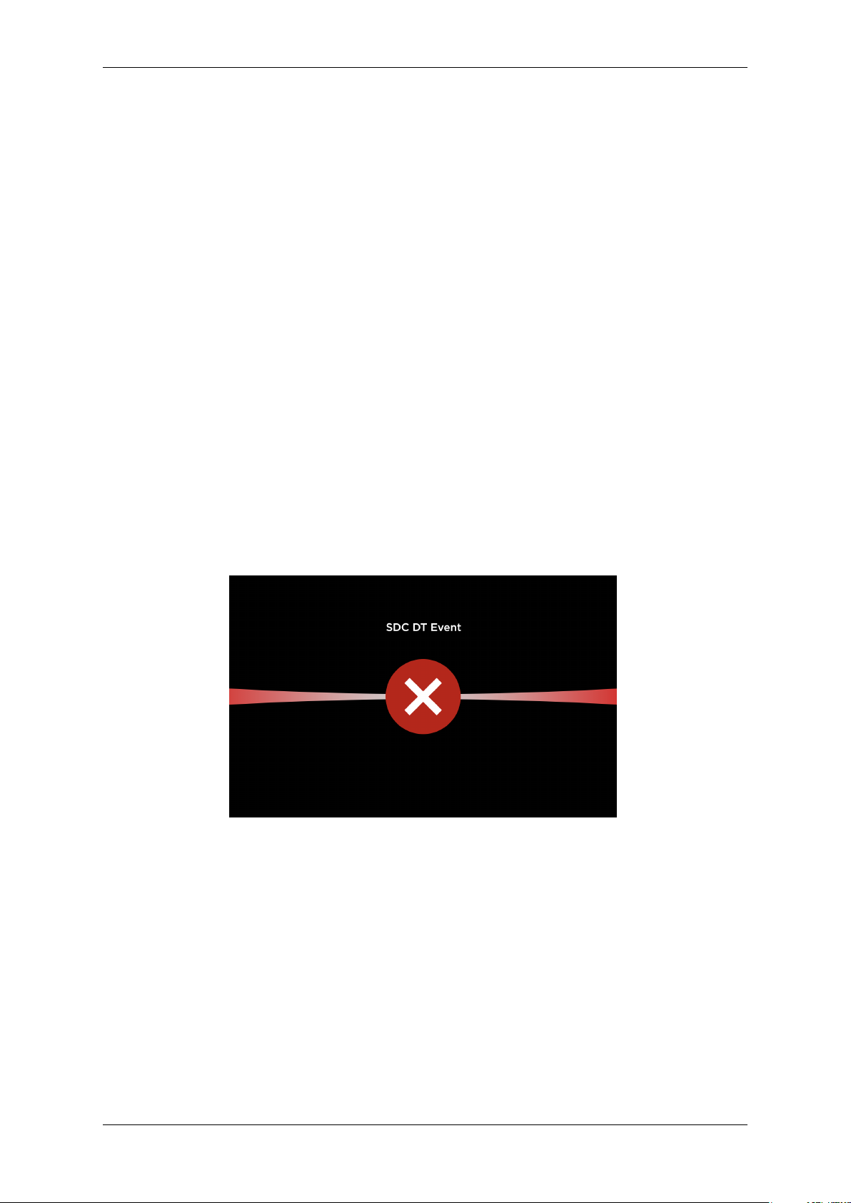
The G7SDC will display a “DT event” screen; the G7UPC will display a fast (twice a second) red keypad
LED indication:
Fig. 2.3: SDC Destructive Tamper (DT) event screen
In contrast, the removal tamper response is intentionally less drastic. Removal tamper sensors protect
a unit that is intact: it may have been removed – even maliciously – from a system in which it was
integrated, but the unit’s integrity has not been violated and it is still operational (albeit in a restricted
mode). Significantly its cryptographic keys have not been erased, although it remains incapable of
financial transactions until restored to normal operation from the removal-tampered state. If necessary
the unit can still perform a DSR.
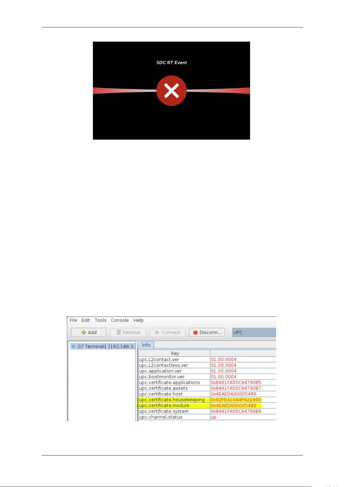
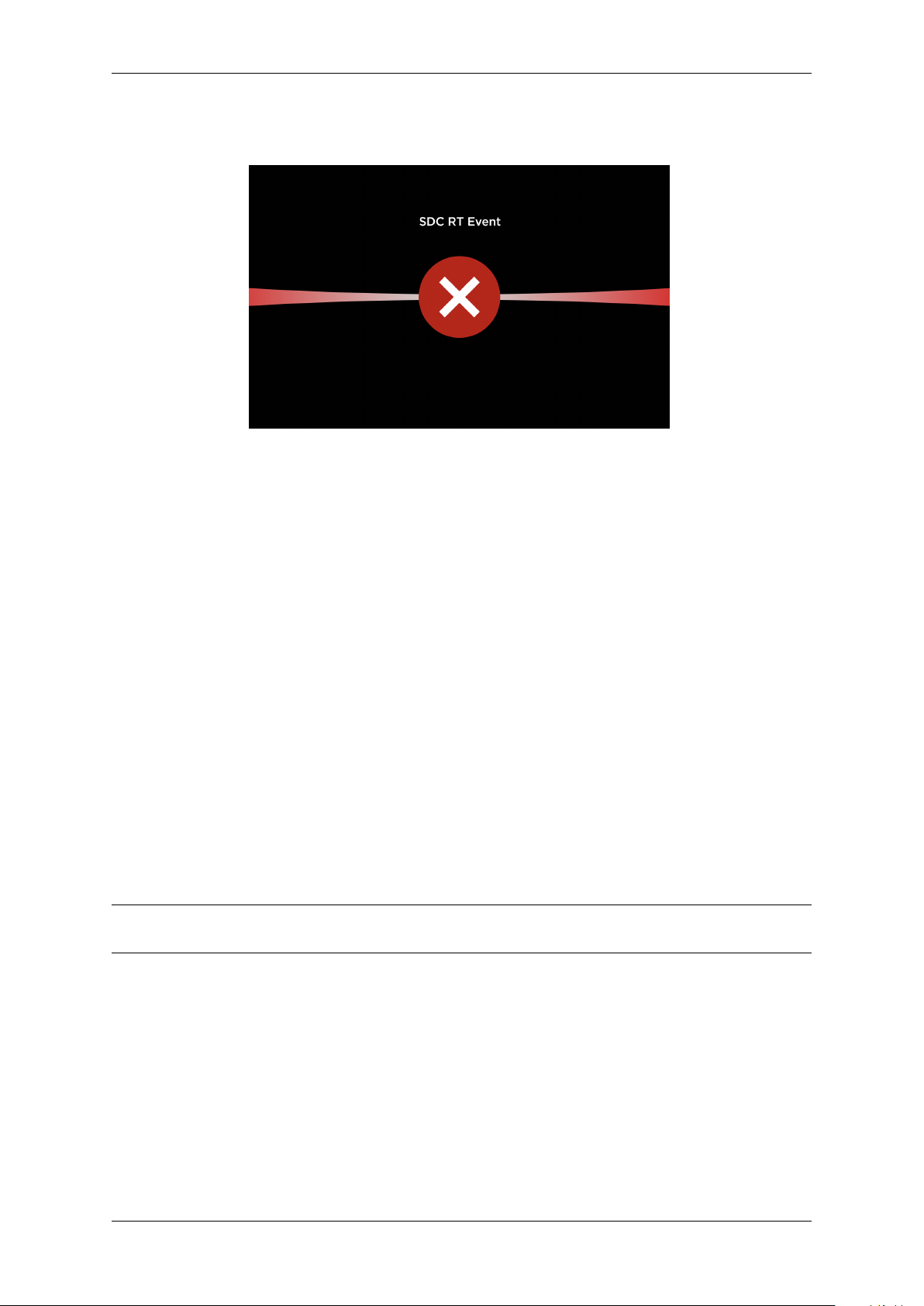
The G7SDC will display a “RT event” screen; the G7UPC will display a slow (once a second) red keypad
LED indication:
Chapter 2. Shipment Verification 6
Page 10
G7OPT Integrator Manual, DWI-00175 S1 R15
Fig. 2.4: SDC Removal Tamper (RT) event screen
If this occurs, follow the exception escalation process defined in §2.5.2 Exception Escalation.
2.3.2 Hardware Certification Status
The second test – assuming the device has booted successfully – is to check that its certificates are
loaded and intact.
This test requires the use of TMSlite to query the key-store status using the following steps:
1. Connect the terminal to the workstation that is running TMSlite, with an intermediate protocol
converter such as Invenco’s external application-software controller.
2. (First time only) Click Add, enter the terminal connection details, then click OK.
3. Select the terminal from the left-hand list, click Connect, then select “UPC” from the filter dropdown list.
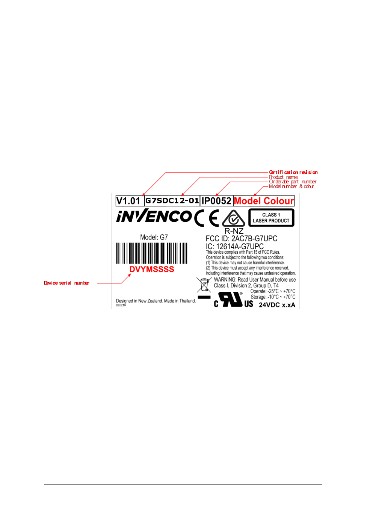
4. Scroll down the list and make sure the properties upc.certificate.housekeeping and
upc.certificate.module are present and not empty. If either property is missing, follow the
exception escalation process defined in §2.5.2 Exception Escalation.
5. Repeat for the SDC by selecting “SDC” from the filter drop-down list, and make sure the properties
sdc.certificate.housekeeping and sdc.certificate.module are present and non-empty.
Fig. 2.5: TMSlite – UPC certificate entries (red text example only)
Chapter 2. Shipment Verification 7
Page 11

G7OPT Integrator Manual, DWI-00175 S1 R15
Note: For more details on using TMSlite, please refer to the TMSlite manual.
Chapter 2. Shipment Verification 8
Page 12
G7OPT Integrator Manual, DWI-00175 S1 R15
2.4 Version Verification
Before a unit is deployed into a production environment, version information should be validated to
ensure it is correct.
Use the following process to verify the hardware certification revision and software version information.
2.4.1 Hardware Certification Revision
Ideally, a hardware certification revision number check can be done at the same time as verifying the
serial number.
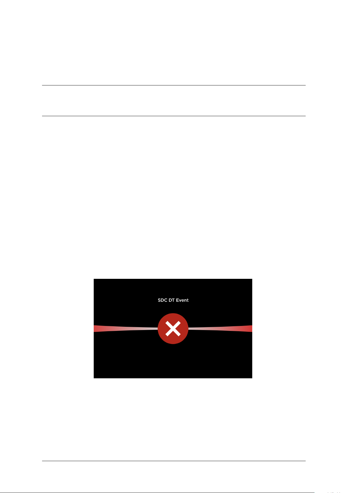
On the back of each unit is a product information sticker which contains, amongst other information, a
serial number and the hardware certification revision number.
Inspect this sticker and confirm the certification revision is correct.
Fig. 2.6: G7SDC serial number and hardware certification revision number
Chapter 2. Shipment Verification 9
Page 13

G7OPT Integrator Manual, DWI-00175 S1 R15
Fig. 2.7: G7UPC serial number and hardware certification revision number
Note: The red content in the above images is for illustrative purposes for this document and must not
exist on actual product labels.
2.4.2 Software Version Numbers
To obtain the core security modules’ version information, the terminal management interface will need
to be interrogated.
Using TMSlite or an in-house proprietary terminal management tool, retrieve the version information
and validate the information tags below.
Note: The paramount firmware-versions have the tags "upc.root.ver" and "sdc.root.ver" for their
respective devices. These versions are controlled by the build system which ensures that all firmware
components – including the Boot Monitor, Root Filesystem and Tamper Monitor – are built and versioned
at the same time.
• Unified PIN pad and Card-Reader: "upc.*.ver", where * is one of:
– hw
– bootmonitor
– init
– kernel
– root
– safekernel
– saferoot
– emvl1
• Secure Display Unit: "sdc.*.ver", where * is one of:
Chapter 2. Shipment Verification 10
Page 14

G7OPT Integrator Manual, DWI-00175 S1 R15
– hw
– bootmonitor
– init
– kernel
– root
– safekernel
– saferoot
– softkey
– touchscreenfrm
Chapter 2. Shipment Verification 11
Page 15

G7OPT Integrator Manual, DWI-00175 S1 R15
2.5 Communications
2.5.1 Receipt Verification
Invenco requests confirmation that the shipment has been received in full. This should be sent to
orders@invenco.com.
This communication must confirm the following:
• Expected quantity has been received.
• All packages/boxes are in good order and security seals intact.
• All serial numbers are accounted for.
2.5.2 Exception Escalation
Should any of the checks detailed in §2.2 Shipment Checks identify that the delivery has been
compromised, or if the checks detailed in §2.3 Integrity Verification and §2.4 Version Verification are
not correct, the following escalation process must be followed:
• Send an email to orders@invenco.com detailing the exception, including all the evidence outlined
in the verification processes above.
• If possible, follow through with a phone call to Invenco using the contact details provided on the
contact page of the Invenco website: http://www.invenco.com/contact
• Notify the shipping/courier of this exception if applicable.
Chapter 2. Shipment Verification 12
Page 16
CHAPTER 3
Tampers
3.1 Background – Tamper Types
Many Invenco products support two types of tamper protection; in increasing order of security they are:
• removal tamper
• destructive tamper, also known as “Destructive Secure Reset” (DSR).
3.1.1 Tamper Indications
A DSR is a dramatic response to what a unit interprets as an integrity violation: the device shuts down
instantly, wiping its security keys and other sensitive information. The device is not ruined but it is
“bricked”: it cannot operate in any capacity and can be disassembled, repaired and reinitialized only
by Invenco – a return-to-base procedure. Returning a destructive-tampered unit to Invenco requires an
auditable process with formal changes of custody, probably including packaging, transport and staging.
The G7SDC will display a “DT event” screen; the G7UPC will display a fast (twice a second) red keypad
LED indication:
Fig. 3.1: SDC Destructive Tamper (DT) event screen
In contrast, the removal tamper response is intentionally less drastic. Removal tamper sensors protect
a unit that is intact: it may have been removed – even maliciously – from a system in which it was
integrated, but the unit’s integrity has not been violated and it is still operational (albeit in a restricted
mode). Significantly its cryptographic keys have not been erased, although it remains incapable of
financial transactions until restored to normal operation from the removal-tampered state. If necessary
the unit can still perform a DSR.
DWI-00175 S1 R15 13
Page 17
G7OPT Integrator Manual, DWI-00175 S1 R15
The G7SDC will display a “RT event” screen; the G7UPC will display a slow (once a second) red keypad
LED indication:
Fig. 3.2: SDC Removal Tamper (RT) event screen
3.2 Removal Tampers
Removal tampers are designed with integrators and their agents in mind; they maintain financial security
while allowing legitimate operations, such as installation or swap-out by service staff. While in the
removal-tamper state, the following operations are possible using TMSlite:
• clearing removal tampers
• installing packages
• retrieving logs
The following sections describe the steps for:
• connecting an Invenco product to external tamper sensors that will protect it within an integrated
system
• clearing the removal-tamper state and promoting the unit to normal operation.
The reverse steps, for removing a unit, need no explanation; they should be straightforward and largely
mechanical. In contrast with installing a device and clearing its removal-tampered state, cryptographic
authentication is unnecessary. The main security considerations when removing a unit are to avoid an
accidental DSR in the process and not to lose it afterwards.
Note: It is strongly recommended to retrieve all logs before unit removal, for problem-solving and
root-cause analysis.
Chapter 3. Tampers 14
Page 18
G7OPT Integrator Manual, DWI-00175 S1 R15
3.2.1 Installation with Removal-Tamper Sensors
1. Obtain access to where the unit will be integrated into its system, paying attention to authorisation
by accredited staff.
2. Obtain custody of the unit and any documentation, cables and other ancillary products.
Adhere to the requirements for custody change, unpacking, etc. in [G7INTSEC] as appropriate.
3. Mount the unit, and others which it will be connected to, in accordance with the integrator’s
instructions and those of Invenco.
See §5.1 G7SDC Installation Guide or §5.2 G7UPC Installation Guide for details. If instructions
conflict, Invenco’s must take precedence; failure to observe this may compromise the unit’s
security and/or void its standards certification.
4. Connect the unit to all others that it is being integrated with.
Tamper connections will vary according to whether the Invenco unit is integrated standalone or in
an Invenco housing. Both methods are described in the appended installation guides. Removal
tampers are likely to have been connected already in the course of mounting the unit; additional
connections for tampers should be unnecessary.
3.2.2 Removal-Tamper Clearing and Promotion to Normal Operation
1. The unit is now integrated into the system; it is in the removal-tampered state. Power it up and
verify that restricted-mode operation is possible.
In removal tampered state:
• the UPC will display a slow (once a second) red flashing LED
• the SDC will display a “removal tamper” error message
2. To clear the removal-tampered state and enable the unit for normal operation requires a
cryptographically authenticated challenge and response between it and an authorisation device.
This transaction is performed under dual control, the two parties being a field engineer and a
control-centre operator.
(a) The field engineer must first request a challenge token from the integrated unit. This is
achieved by:
i. Connect the terminal to the workstation running TMSlite.
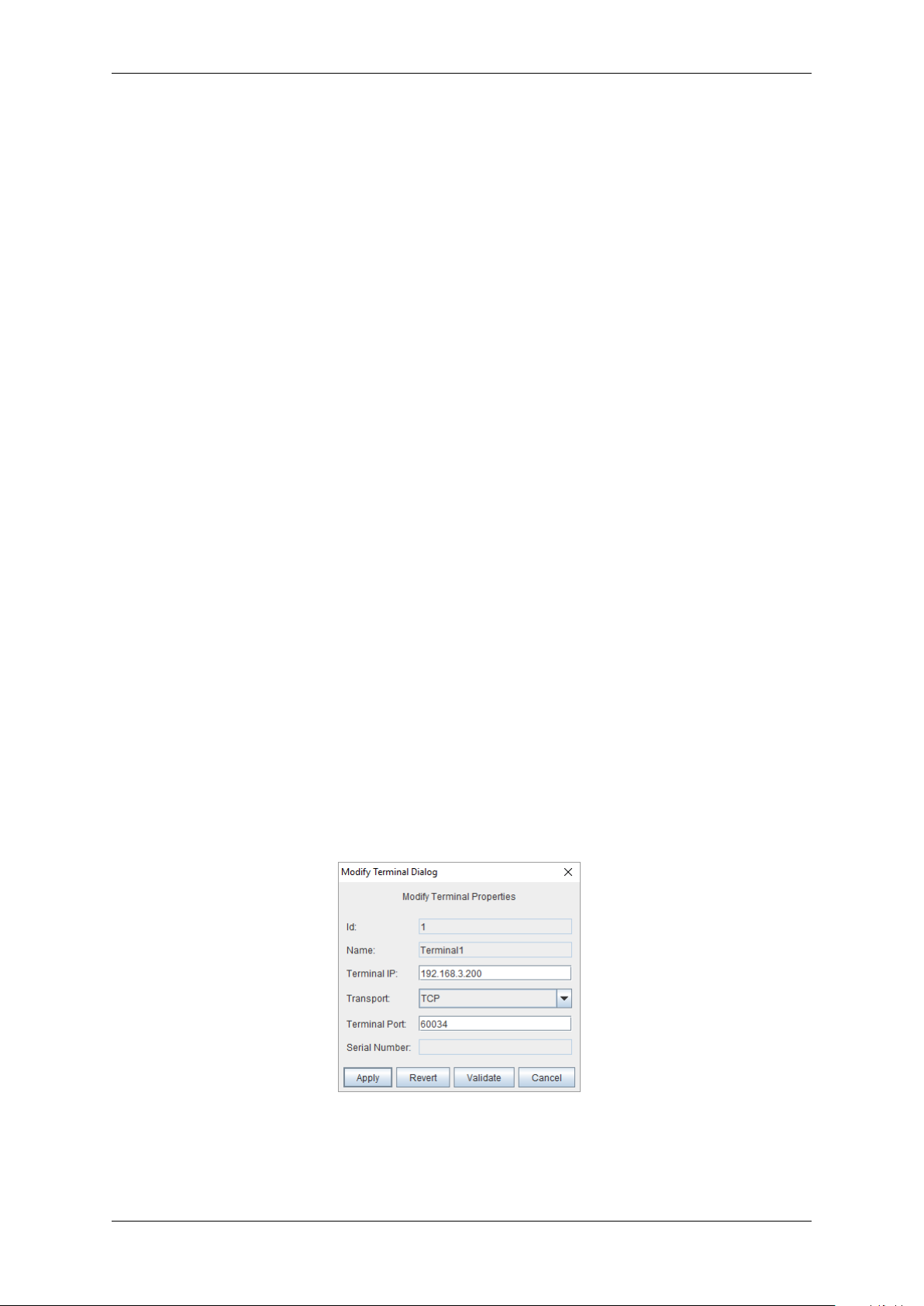
ii. (First time only) Click Add, enter the terminal connection details, then click OK.
Fig. 3.3: Terminal connection details.
iii. Select the terminal from the left-hand list, then click Connect.
Chapter 3. Tampers 15
Page 19
G7OPT Integrator Manual, DWI-00175 S1 R15
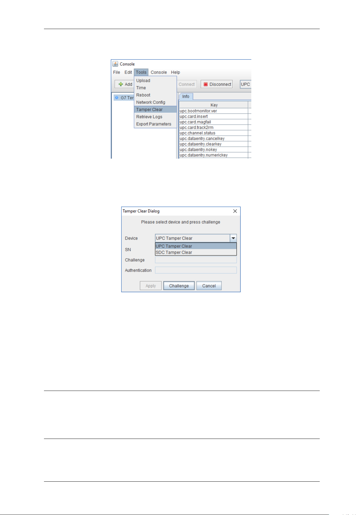
iv. Selecting the menu option Tools > Tamper Clear.
Fig. 3.4: TMSlite “Tamper Clear” menu option
v. Choosing either “UPC Tamper Clear” or “SDC Tamper Clear” from the dialog box drop-
down menu.
Fig. 3.5: TMSlite “Tamper Clear” dialog box
vi. Clicking “Challenge” to display the required challenge token.
(b) Next, the field engineer must log in to the control centre and post the token and the device’s
serial number into an installation authorisation request.
(c) The control-centre operator must now approve the request (if they deem it valid), then
generate an authorisation token and return it to the field engineer.
(d) The field engineer submits the authorisation token to the device by keying it in manually and
clicking “Apply”.
Note:
• The display unit (SDU/SDC) and keypad (UPC) must be connected together throughout this
process.
• The challenge / response operation must be completed within 30 minutes; if not, a new challenge
token must be generated and the process repeated.
The unit itself is now in normal mode and ready for operation. Devices that it is integrated with may
require additional steps; consult product manuals.
Chapter 3. Tampers 16
Page 20
G7OPT Integrator Manual, DWI-00175 S1 R15
3.3 Retrieving logs and exporting parameters
It is strongly recommended to retrieve all logs before unit removal, for problem-solving and root-cause
analysis.
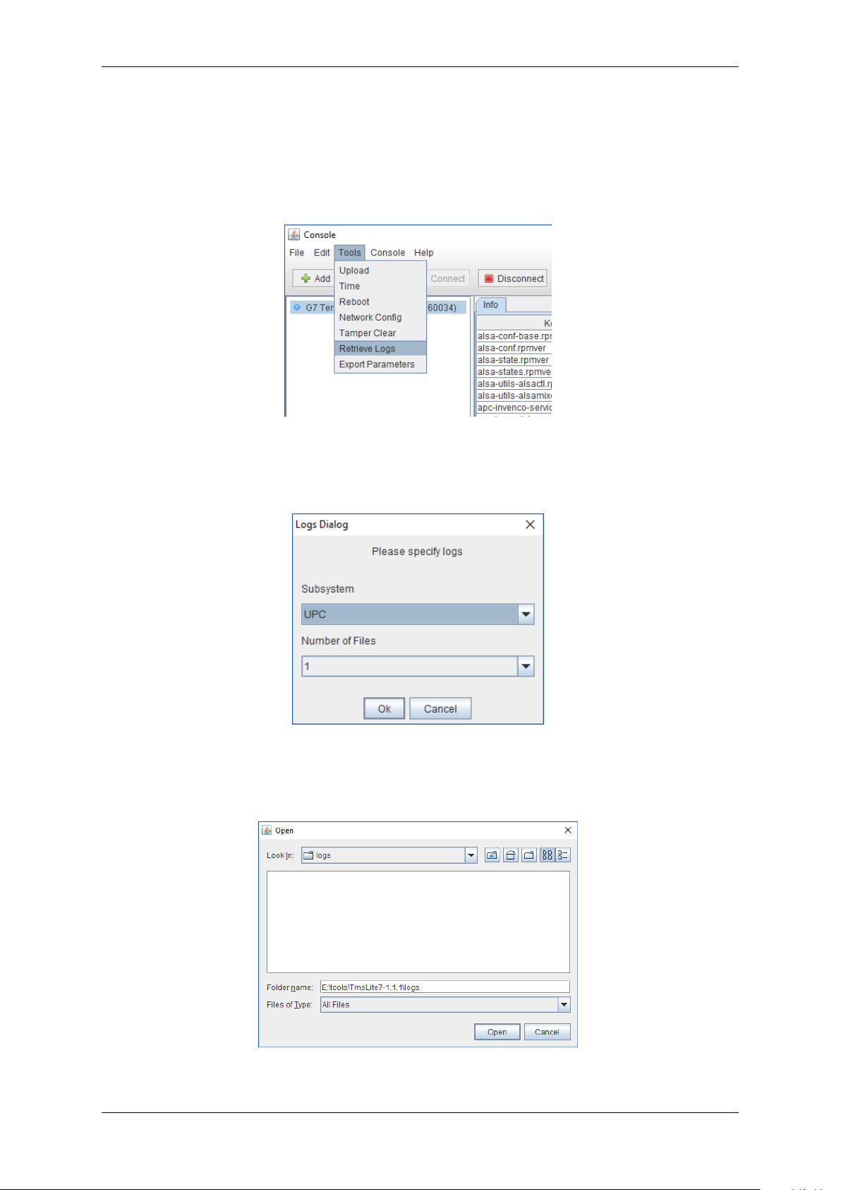
1. Select menu item Tools > Retrieve Logs:
Fig. 3.6: Menu item Tools > Retrieve Logs
2. Select the desired subsystem (e.g. UPC) and the number of log files to retrieve, then click OK.
Fig. 3.7: Specify logs to retrieve
3. Specify the location to save the retrieved log files, then click Open.
Fig. 3.8: Specify save location
Chapter 3. Tampers 17
Page 21
G7OPT Integrator Manual, DWI-00175 S1 R15
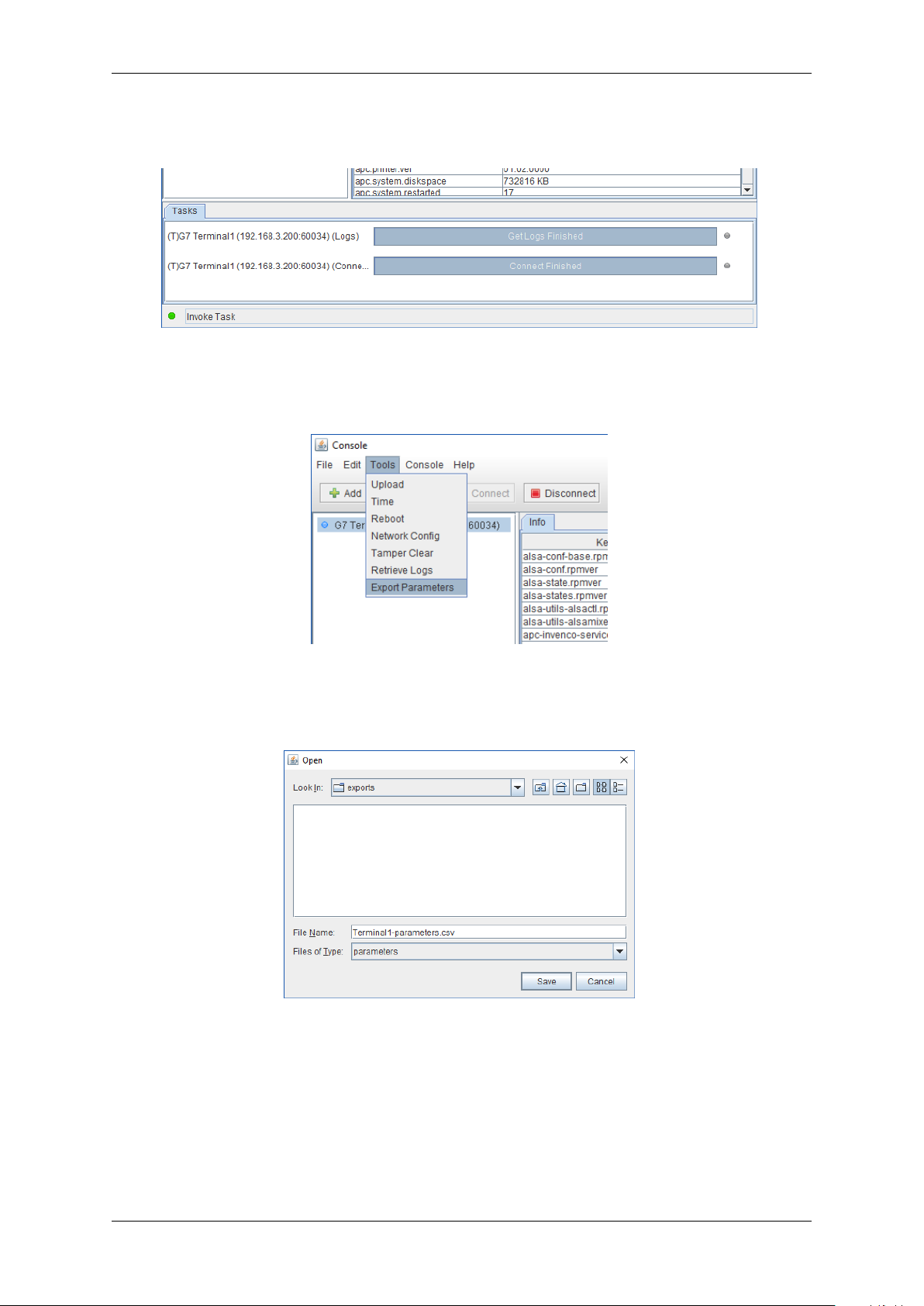
4. The Task list will display “Get Logs Finished” when operation is complete and the log files have
been saved to the specified location.
Fig. 3.9: Task list: “Get Logs Finished”
5. Select menu item Tools > Export Parameters:
Fig. 3.10: Menu item Tools > Export Parameters
6. Specify the location to save the exported parameter file, then click Save.
Fig. 3.11: Specify save location
7. The exported parameters will be saved in the specified location as a comma-separated-value
(CSV) file.
Chapter 3. Tampers 18
Page 22

CHAPTER 4
Key Injection
4.1 Background
In order to perform financial operations, each terminal must be injected with a cryptographic key at time
of installation. Keys are injected using Invenco Cloud Solutions (ICS), a secure web-service for remotely
managing and monitoring Invenco terminals; this process is known as Remote Key Injection (RKI).
4.2 Terminology
A terminal is associated with a site. A site is associated with a customer; a customer is associated with
both a key group and a vendor, from whom the terminals have been purchased.
4.3 Installation
Completing installation requires a terminal to be registered with a specific customer within ICS, and
“moved” to the associated site. This initiates an automatic RKI request, which must be approved by two
separate authorised customer personnel, within the web-interface.
Once the RKI request has been processed, a job is scheduled within ICS to perform key injection.
This occurs when the terminal is connected and powered-up for the first time via an available internet
connection, either on-site, or at an appropriate staging area.
Once key injection has occurred, the terminal is ready to perform financial operations, e.g. accept credit
card payments.
4.4 Swap-outs
Swapping out a terminal requires the old terminal to be moved within ICS, from the customer site to
a designated repair site. A replacement terminal is then installed as normal, following the procedure
described for §4.3 Installation.
DWI-00175 S1 R15 19
Page 23

CHAPTER 5
Appendices
5.1 G7SDC Installation Guide
5.1.1 Introduction
The G7SDC (Secure Display Controller) is a device for presenting both secured and open information,
and for receiving customer selections during transaction processing. Its design is intended to comply
with applicable security certification requirements of the Payment Card Industry (PCI). The G7SDC is
intended to operate in conjunction with the G7UPC (Unified PIN pad / Card-reader) and an external
application host.
The SDC is a highly secure device. However, some of its security features are reliant on the method of
installation; therefore please pay careful attention to the requirements outlined in this document.
DWI-00175 S1 R15 20
Page 24

G7OPT Integrator Manual, DWI-00175 S1 R15
5.1.2 Installation
5.1.2.1 Environment
• The SDC must be mounted in some form of cabinet that provides adequate protection of the
SDC’s rear from the environment.
• The cabinet must restrict access to the rear of the SDC by unauthorized persons.
• The mounting surface must be vertical and flat.
• The mounting surface should not be in the direct line-of-sight of any video camera, unless the
user’s body will provide adequate blocking of that view of the SDC in use.
• The SDC can be mounted at any height that is suitable for the majority of users; this would typically
be above the mounted height of the associated UPC.
• Although the SDC is weather-resistant, the cabinet should be sheltered from rain, or should
provide a canopy.
5.1.2.2 Tools
For this guide, we assume that the cabinet has been prepared with the appropriate cut-out prior to
installation. Please see §5 Cutout for details.
The only tool required for installation is a 3mm hex (Allen) key. The shaft of the key should be at least
100mm long for ease of use.
5.1.2.3 Method
1. Check that the cabinet cut-out is free of burrs and ripples and that all the mounting holes are clear.
2. Check the SDC packaging for signs of tampering. If the factory seals are not intact DO NOT install
the SDC.
3. Unpack the SDC carefully. Again check for signs of tampering, both with the SDC and with its
rubber gasket.
4. Check that the rubber gasket is placed the correct way up on the SDC. It must be seated flat on
the SDC case:
Fig. 5.1: Gasket Upside-down
Chapter 5. Appendices 21
Page 25

G7OPT Integrator Manual, DWI-00175 S1 R15
Fig. 5.2: Gasket Right Way Up
5. Place the SDC from the outside of the cabinet into the cut-out. Check that the SDC sits flat against
the cabinet and that the gasket is not rippled or folded anywhere.
Fig. 5.3: Mounting Holes
6. Insert the sixteen mounting screws around the SDC but do not tighten them.
7. Ensure the SDC is aligned nicely in the cutout, then tighten all sixteen mounting screws.
8. Discard the SDC packaging in accordance with local regulations.
Chapter 5. Appendices 22
Page 26

G7OPT Integrator Manual, DWI-00175 S1 R15
5.1.3 Connection
This document assumes that the SDC will be installed at the same time as both a G7UPC and a G7APC.
Fig. 5.4: Connections
There are at least seven connections to be made to the SDC:
1. Connect a DC power cable between the “APC PWR” socket and the “PWR OUT-L” socket on the
APC.
2. Connect a USB A-B cable between the “APC USB” port and a “USB-L” port on the APC.
3. Connect an HDMI cable between the “APC VIDEO” socket and the “LCD-L” socket on the APC.
4. Connect a DC power cable between the “UPC PWR” socket and the “PWR” socket on the UPC.
5. Connect a USB A-B cable between the “UPC USB” port and the “USB” port on the UPC.
6. Connect an audio cable between the “UPC AUDIO” socket and the “AUD” socket on the UPC.
7. Connect a USB A-B cable between the “BAR CODE” socket and the “BARCODE USB” port on
the UPC.
Chapter 5. Appendices 23
Page 27

G7OPT Integrator Manual, DWI-00175 S1 R15
5.1.4 Basic Maintenance
5.1.4.1 Cleaning
The G7 modules are intended for use in the harsh environment of a fuelling station forecourt. As such
they need little maintenance to keep them looking good.
• Use a soft cloth dampened with water for daily cleaning.
• If grime builds up, use a diluted mild detergent on a soft cloth.
• Take extra care when cleaning the display window:
– Use only a diluted, mild, liquid soap or detergent and a soft, clean cloth.
– Rinse the detergent off carefully, using minimal pressure, before drying the display with a
clean, dry, lint-free or microfibre cloth.
– CAUTION Do NOT rub the display if it is dry. Accumulated dust may scratch the surface and
degrade the barcode reading function.
• CAUTION Do NOT use petroleum-based solvent cleaners. They may damage surfaces, making
the unit much harder to clean, and shorten the life of the parts.
• CAUTION Do NOT use a high-pressure hose to clean the SDC.
5.1.4.2 Security Checks
The module is a transaction-processing device; it will come to the attention of fraudsters. It must be
inspected daily:
• for signs of tampering; and
• for any unauthorised devices that may have been attached or overlaid onto the module.
If there are any signs of tampering of any kind:
1. immediately stop the normal operation of the G7 system
2. log a security issue with the support agent’s helpdesk
3. take photos of any unauthorised devices or modifications
4. record details of anyone subsequently interfering with the G7 system.
Where destructive or malicious tampering has occurred or is suspected, the affected module/s must
be returned to Invenco for inspection, validation and possibly repair and reinitialization. Procedures for
secure removal, shipping and changes of custody must be followed throughout by all parties involved.
If there are no signs of tampering but it is known or suspected that security keys have been
compromised, the keys must be replaced with new ones.
5.1.4.2.1 Signs of Tampering
Check for the following:
• damage to, or apparent discoloration of any of the plastic parts
• any visible wires anywhere on the module
• on a UPC: shims, scratches or filed surfaces anywhere around or in the mouth of the card reader
• holes in any surface of the plastic parts (particularly above the keypad area on a UPC).
• functional indications that the module is in removal-tampered mode:
– On a G7SDC:
Chapter 5. Appendices 24
Page 28

G7OPT Integrator Manual, DWI-00175 S1 R15
a secure prompt will be shown, overwriting any other display, which indicates clearly that
*
the module is in removal-tampered mode; and
the module and its companion UPC will no longer perform transactions normally – for
*
example, touchscreen functions will all be disabled.
– On a G7UPC:
the module’s LEDs will flash red, alternating between on and off every half-second
*
the module and its companion SDC will no longer perform transactions normally – for
*
example, PIN entry will be disabled.
• functional indications that the module has been destructively tampered:
– On a G7SDC:
a secure prompt will be shown, overwriting any other display, which indicates clearly that
*
the module is in destructive-tampered mode; and
the module and its companion UPC will no longer perform transactions normally.
*
– On a G7UPC:
the module’s LEDs will flash red, alternating between on and off every quarter-second
*
the module and its companion SDC will no longer perform transactions normally.
*
5.1.4.2.2 Attached Devices and/or Overlays
Check whether:
• the surfaces of the module’s various plastic parts do not line up as they should
• there are foreign devices attached to the module, including inside the cabinet
• you have a haunting feeling the module doesn’t look quite like as should.
5.1.4.3 Battery Replacement
5.1.4.3.1 Battery Type and Precautions
The backup battery is a 3.6V, 2400mAh, non-rechargable one. It must be replaced by a trained
technician only.
The battery employs lithium thionyl chloride technology; its contents are toxic.
CAUTION: THERE IS A RISK OF EXPLOSION IF THE BATTERY IS REPLACED BY AN INCORRECT
TYPE. DISPOSE OF USED BATTERIES ACCORDING TO THE INSTRUCTIONS.
The battery must not be recharged, short-circuited or disassembled; hazardous-waste precautions must
be observed when disposing of it.
5.1.4.3.2 Procedure
The G7SDC includes a supercap which can provide power for long enough only to perform a graceful
shutdown when all other supplies are lost. If the external DC supply is disconnected, the supercap
has insufficient capacity to maintain power for long enough to replace the battery. During battery
replacement, therefore, the module’s DC supply should remain connected and turned on; otherwise
the backup supply will droop far enough to cause a destructive tamper.
During battery replacement it is not necessary to remove or even disconnect the module from the system
it is integrated with. This includes removal-tamper sensors; they can remain connected. One or more
external, analogue removal-tamper sensors will probably be triggered in the process but this is normal
when opening a system cabinet containing a G7 secure module. (Removal-tampering the G7SDC will
Chapter 5. Appendices 25
Page 29

G7OPT Integrator Manual, DWI-00175 S1 R15
suspend normal operation of the module and of the system as a whole – in particular it will temporarily
prevent any financial transactions.)
The battery compartment is enclosed within the SDC’s plastic housing. It is accessed from the rear of
the module, by undoing a captive Philips #2 screw then removing the lid of the compartment. The battery
is secured within the compartment by a Velcro strip. After removing the compartment lid, carefully
“unstick” the strip, disconnect the battery and remove it.
The battery connector is keyed; it cannot be plugged in with incorrect polarity. Fit a replacement battery,
plug in its connector and resecure the compartment lid. Check that no connections to the G7SDC have
been displaced then close and secure the system cabinet.
Follow the instructions under §3 Tampers to clear the removal-tampered state and restore the module
and overall system to normal operation.
Ensure that details of the battery change are recorded correctly.
Chapter 5. Appendices 26
Page 30

G7OPT Integrator Manual, DWI-00175 S1 R15
5.1.5 Drawings
Fig. 5.5: General Arrangement
Chapter 5. Appendices 27
Page 31
G7OPT Integrator Manual, DWI-00175 S1 R15
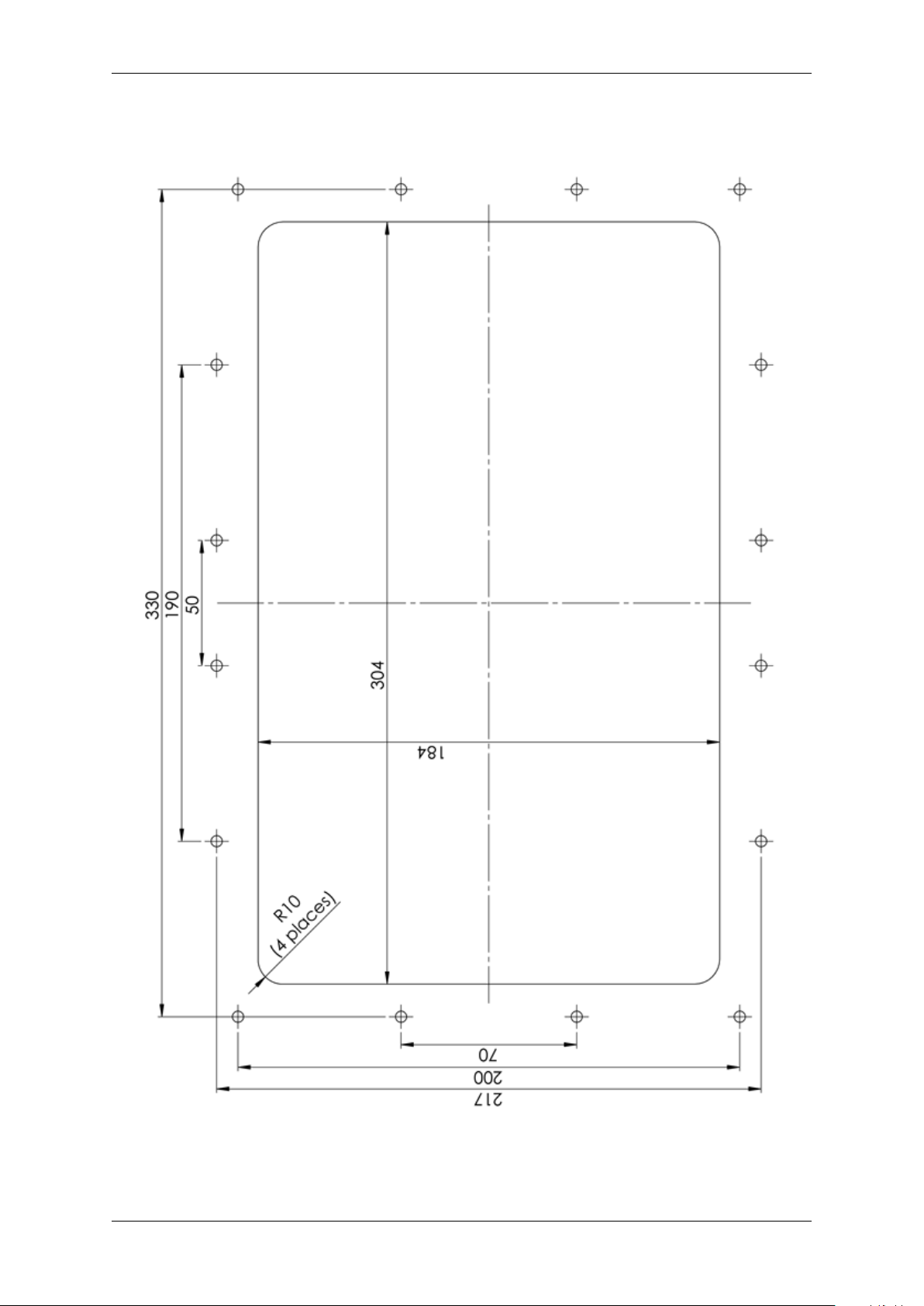
Dimensions are in millimetres
Do Not Scale
Fig. 5.6: Cutout
Chapter 5. Appendices 28
Page 32

G7OPT Integrator Manual, DWI-00175 S1 R15
5.2 G7UPC Installation Guide
5.2.1 Introduction
The G7UPC (Unified PIN pad / Card Reader) is a PCI-compliant device for the secure reading of cards
and entry of numeric data. It is intended to operate in conjunction with the G7SDC (Secure Display
Controller).
The UPC is a highly secure device. However, some of its security features are reliant on the method of
installation; therefore please pay careful attention to the requirements outlined in this document.
To cater for the requirements of system integrators, Invenco supplies the UPC in a rigid, plastic housing
designed for the purpose. This configuration is the focus of these installation instructions.
The removal-tamper sensors on the UPC’s keypad fascia have been armed already, in the process of
fitting the module into the housing; they will be activated if it is removed. Additional removal-tamper
connections are supplied for use by integrators:
• two clusters, of four tamper pills each, at the lower corners on the back of the plastic housing.
(See §5 Housing Removal-tampers.) These will be armed when the housing is installed (from the
front) into the integrator’s cabinet.
• two external, analogue current-loops. One of these is used with a flexible printed circuit to protect
against removal of the UPC from its plastic housing. The other is available for connection to a
sensor supplied by the integrator.
Chapter 5. Appendices 29
Page 33

G7OPT Integrator Manual, DWI-00175 S1 R15
5.2.2 NFC Antenna Installation
The G7UPC supports a Near-field Communication contactless card-reader for:
• presenting both secured and open information
• receiving customer selections during transaction processing.
5.2.2.1 Antenna Kit Description
The contactless card-reader requires an external antenna. The antenna is supplied in a plastic
enclosure with two cables attached:
• an antenna cable terminated with a subminiature MCX plug
• a LED-power and -signal cable terminated with a Molex Micro-Fit 3.0 six-way plug.
A large, flanged nut is included, for securing the antenna against the system panel.
Also supplied is a gasket to prevent ingress of moisture and dust.
Fig. 5.7: NFC Antenna Kit
5.2.2.2 Antenna Cutouts
Fig. 5.8: Antenna Wireframe
Chapter 5. Appendices 30
Page 34

G7OPT Integrator Manual, DWI-00175 S1 R15
1. For the antenna to function correctly the following must be observed:
• There must be at least 2cm clearance around the top, bottom and sides of the antenna.
• The system panel must not be electrically conductive within the above clearance region –
for example, it must not be metallic. (Panels supplied by Invenco are non-conductive and
pre-drilled.)
• There must be at least 4cm clearance in front of the antenna.
2. The following holes in the panel are required – see §5 Antenna Wireframe. (Note that no drilling
is allowed on a fuel-outlet forecourt. As mentioned above, panels supplied by Invenco are predrilled.)
• A 34mm round hole, concentric with the 76mm-square antenna enclosure.
• Centred 28mm above it, a 4mm round hole to accept the orientation pin on the antenna.
5.2.2.3 Installation Sequence
While not necessary, it may simplify connecting the cables if the NFC antenna is mounted into the panel
before the G7UPC.
1. Unscrew the large, flanged securing nut from the rear of the antenna. Carefully pull the cables
through the nut to remove it. Set the nut aside.
2. Pull the gasket back along the cables, far enough to gain access to the backing that covers its
adhesive face. Peel off then tear the backing to remove it, then discard it.
3. Align the small hole in the gasket with the orientation pin on the antenna. Seat the gasket into the
antenna, with the pin protruding. Align the gasket so it will lie flat, entirely within the lip around
the edge of the antenna. Press down over the rear surface of the gasket to stick it securely to the
antenna.
4. From the front of the panel, feed the cables through the large mounting hole. (Note that if Invenco’s
Americans with Disabilities Act-compliant keypad is installed the antenna is mounted above it.)
5. At the rear of the panel, feed the cables through the nut from its flanged side.
6. From the front of the panel, turn the antenna so the pin aligns with the orientation hole in the panel
then carefully insert the antenna into the panel. (The weight of the cables will hold it in place
temporarily.)
7. Carefully tighten the nut onto the threaded portion of the antenna. When the nut reaches fingertightness, a final check from the front of the panel will help to ensure the antenna is “squared”
neatly and the gasket is not misaligned.
8. Finish tightening the nut. (Avoid overtightening it; this will ensure the gasket functions correctly.)
Chapter 5. Appendices 31
Page 35

G7OPT Integrator Manual, DWI-00175 S1 R15
Fig. 5.9: NFC Nut, Tightened, Rear View
There is no need to connect the cables to the G7UPC immediately but remember to do so before
finishing the installation.
5.2.3 UPC Installation - Invenco Housing Option
5.2.3.1 Environment
• In this configuration the UPC is supplied in a housing that provides adequate protection of the
UPC’s rear from the environment.
Invenco’s housing is designed specially for the UPC, with attention to security, standards
compliance and usability. It is made of rigid plastic, coloured black for aesthetic and security
reasons. (Attempts at tampering show up against a black-gloss background.) When mounted
against a flat, vertical surface as described here, the housing presents the keypad at the optimum
angle for access and privacy.
• The housing restricts access to the rear of the UPC by unauthorized persons. In turn, the
integrator’s system cabinet will restrict access to the rear of the housing and its cables.
• The mounting surface for the housing, with the UPC inside it, must be vertical and flat.
• The mounting surface should not be in the direct line-of-sight of any video camera, unless the
user’s body will provide adequate blocking of that view of the UPC in use.
• The housing should be mounted in the cabinet so that the UPC is at a height suitable for most
users. (Invenco recommends a height of 1200mm for the ‘5’ key.)
Chapter 5. Appendices 32
Page 36

G7OPT Integrator Manual, DWI-00175 S1 R15
• Although the UPC is weather-resistant, the housing and UPC should be sheltered from rain or a
canopy should be provided.
5.2.3.2 Tools
For this guide, we assume that the cabinet has been prepared with the appropriate cut-out prior to
installation. Please see §5 UPC Cutout for details.
The only tool required for installation is a 3mm hex (Allen) key. The shaft of the key should be at least
100mm long for ease of use.
5.2.3.3 Method
1. Check that the cabinet cut-out is free of burrs and ripples and that all the mounting holes are clear.
2. Check the UPC packaging for signs of tampering. If the factory seals are not intact DO NOT install
the UPC.
3. Unpack the UPC carefully. Again check for signs of tampering, both with the UPC and with its
rubber gasket.
4. Check that the rubber gasket is placed the correct way up, flat against the rear of the housing:
Fig. 5.10: Gasket Upside-down
Fig. 5.11: Gasket Right Way Up
5. Place the housing containing the UPC from the outside of the cabinet into the cabinet cut-out.
Check that the housing sits flat against the cabinet and that the gasket is not rippled or folded
anywhere.
Chapter 5. Appendices 33
Page 37

G7OPT Integrator Manual, DWI-00175 S1 R15
Fig. 5.12: Mounting Holes
6. Insert mounting screws in the top and bottom centre holes of the UPC but do not tighten them.
7. Insert the remaining six screws, three along each side.
8. Ensure the housing is aligned neatly in the cutout, then tighten all eight mounting screws.
This will arm the eight removal-tamper sensors (coloured red in the figure, see §5 Housing
Removal-tampers). These tampers will become active when the UPC is promoted from its
removal-tampered state to normal operating mode.
Chapter 5. Appendices 34
Page 38

G7OPT Integrator Manual, DWI-00175 S1 R15
Fig. 5.13: Housing Removal-tampers
9. Discard packaging in accordance with local regulations.
Chapter 5. Appendices 35
Page 39

G7OPT Integrator Manual, DWI-00175 S1 R15
5.2.3.4 Connection
This section assumes that the UPC will be installed at the same time as a G7SDC, NFC antenna and
ADA keypad.
While not necessary, it may simplify connecting the UPC if it is mounted on the system panel after the
NFC antenna and ADA keypad.
Fig. 5.14: UPC Connections
Carefully make the following connections to the UPC:
1. connect a DC power cable between the UPC’s PWR socket and the UPC PWR socket on the SDC
2. connect a USB A-B cable between the UPC’s USB port and the UPC USB port on the SDC
3. connect the audio cable between the UPC’s AUD socket and the UPC AUDIO socket on the SDC
4. connect a USB A-B cable between the UPC’s BARCODE USB socket and the BAR CODE port
on the SDC
5. connect the ADA keypad’s plug to the ADA socket on the UPC
6. connect the NFC antenna’s LED-power and -signal plug to the LED socket on the UPC
7. connect the NFC antenna’s coaxial plug to the ANT socket on the UPC.
Chapter 5. Appendices 36
Page 40

G7OPT Integrator Manual, DWI-00175 S1 R15
Fig. 5.15: NFC Antenna Connections
Chapter 5. Appendices 37
Page 41

G7OPT Integrator Manual, DWI-00175 S1 R15
5.2.4 Basic Maintenance
5.2.4.1 Cleaning
The G7 modules are intended for use in the harsh environment of a fuelling station forecourt. As such
they need little maintenance to keep them looking good.
• Use a soft cloth dampened with water for daily cleaning.
• If grime builds up, use a diluted mild detergent on a soft cloth.
• Take extra care when cleaning the barcode reader window:
– Use only a diluted, mild, liquid soap or detergent and a soft, clean cloth.
– Rinse the detergent off carefully, using minimal pressure, before drying the display with a
clean, dry, lint-free or microfibre cloth.
– CAUTION Do NOT rub the display if it is dry. Accumulated dust may scratch the surface and
degrade the barcode reading function.
• CAUTION Do NOT use petroleum-based solvent cleaners. They may damage surfaces, making
the terminal much harder to clean, and shorten the life of the parts.
• CAUTION Do NOT use a high-pressure hose to clean the UPC. The card-reader opening will fill
with water which may damage the device.
5.2.4.2 Security Checks
The module is a transaction-processing device; it will come to the attention of fraudsters. It must be
inspected daily:
• for signs of tampering; and
• for any unauthorised devices that may have been attached or overlaid onto the module.
If there are any signs of tampering of any kind:
1. immediately stop the normal operation of the G7 system
2. log a security issue with the support agent’s helpdesk
3. take photos of any unauthorised devices or modifications
4. record details of anyone subsequently interfering with the G7 system.
Where destructive or malicious tampering has occurred or is suspected, the affected module/s must
be returned to Invenco for inspection, validation and possibly repair and reinitialization. Procedures for
secure removal, shipping and changes of custody must be followed throughout by all parties involved.
If there are no signs of tampering but it is known or suspected that security keys have been
compromised, the keys must be replaced with new ones.
5.2.4.2.1 Signs of Tampering
Check for the following:
• damage to, or apparent discoloration of any of the plastic parts
• any visible wires anywhere on the module
• on a UPC: shims, scratches or filed surfaces anywhere around or in the mouth of the card reader
• holes in any surface of the plastic parts (particularly above the keypad area on a UPC).
• functional indications that the module is in removal-tampered mode:
– On a G7SDC:
Chapter 5. Appendices 38
Page 42

G7OPT Integrator Manual, DWI-00175 S1 R15
a secure prompt will be shown, overwriting any other display, which indicates clearly that
*
the module is in removal-tampered mode; and
the module and its companion UPC will no longer perform transactions normally – for
*
example, touchscreen functions will all be disabled.
– On a G7UPC:
the module’s LEDs will flash red, alternating between on and off every half-second
*
the module and its companion SDC will no longer perform transactions normally – for
*
example, PIN entry will be disabled.
• functional indications that the module has been destructively tampered:
– On a G7SDC:
a secure prompt will be shown, overwriting any other display, which indicates clearly that
*
the module is in destructive-tampered mode; and
the module and its companion UPC will no longer perform transactions normally.
*
– On a G7UPC:
the module’s LEDs will flash red, alternating between on and off every quarter-second
*
the module and its companion SDC will no longer perform transactions normally.
*
5.2.4.2.2 Attached Devices and/or Overlays
Check whether:
• the surfaces of the module’s various plastic parts do not line up as they should
• there are foreign devices attached to the module, including inside the cabinet
• you have a haunting feeling the module doesn’t look quite like as should.
5.2.4.3 Battery Replacement
5.2.4.3.1 Battery Type and Precautions
The backup battery is a 3.6V, 2400mAh, non-rechargable one. It must be replaced by a trained
technician only.
The battery employs lithium thionyl chloride technology; its contents are toxic.
CAUTION: THERE IS A RISK OF EXPLOSION IF THE BATTERY IS REPLACED BY AN INCORRECT
TYPE. DISPOSE OF USED BATTERIES ACCORDING TO THE INSTRUCTIONS.
The battery must not be recharged, short-circuited or disassembled; hazardous-waste precautions must
be observed when disposing of it.
5.2.4.3.2 Procedure
The G7UPC includes a supercap which can provide power for long enough only to perform a graceful
shutdown when all other supplies are lost. If the external DC supply is disconnected, the supercap
has insufficient capacity to maintain power for long enough to replace the battery. During battery
replacement, therefore, the module’s DC supply should remain connected and turned on; otherwise
the backup supply will droop far enough to cause a destructive tamper.
During battery replacement it is not necessary to remove or even disconnect the module from the system
it is integrated with. This includes removal-tamper sensors; they can remain connected. One or more
external, analogue removal-tamper sensors will probably be triggered in the process but this is normal
when opening a system cabinet containing a G7 secure module. (Removal-tampering the G7UPC will
Chapter 5. Appendices 39
Page 43

G7OPT Integrator Manual, DWI-00175 S1 R15
suspend normal operation of the module and of the system as a whole – in particular it will temporarily
prevent any financial transactions.)
The battery compartment is enclosed within the UPC’s plastic housing. It is accessed from the rear of
the module, by undoing a captive Philips #2 screw then removing the lid of the compartment. The battery
is secured within the compartment by a Velcro strip. After removing the compartment lid, carefully
“unstick” the strip, disconnect the battery and remove it.
The battery connector is keyed; it cannot be plugged in with incorrect polarity. Fit a replacement battery,
plug in its connector and resecure the compartment lid. Check that no connections to the G7UPC have
been displaced then close and secure the system cabinet.
Follow the instructions under §3 Tampers to clear the removal-tampered state and restore the module
and overall system to normal operation.
Ensure that details of the battery change are recorded correctly.
Chapter 5. Appendices 40
Page 44

G7OPT Integrator Manual, DWI-00175 S1 R15
5.2.5 Drawings
Fig. 5.16: General Arrangement
Chapter 5. Appendices 41
Page 45

G7OPT Integrator Manual, DWI-00175 S1 R15
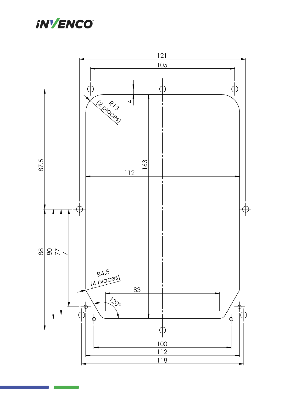
Dimensions are in millimetres
Do Not Scale
Fig. 5.17: UPC Cutout
Chapter 5. Appendices 42
Page 46

G7OPT Integrator Manual, DWI-00175 S1 R15
Fig. 5.18: NFC Antenna Rear View
Chapter 5. Appendices 43
Page 47

Reference Source Document
G7INTSEC “G7OPT Integrator Security Policy”, (DQS-00087)
CHAPTER 6
References
DWI-00175 S1 R15 44
Page 48

Revision 15, 2016-12-02
• Edit FCC and Industry Canada to include antenna gain information in Introduction.
Revision 14, 2016-12-01
• Add FCC and Industry Canada compliance-related statements to Introduction.
Revision 13, 2016-11-28
• Clarify battery-replacement instructions for SDC and UPC wrt leaving external DC supply
connected.
CHAPTER 7
Document History
• Refactor SDC cutout and tamper indications into reST sources common to this doc and
Integrator Security Policy.
• Add SDC label images.
• Pull in Word version of NFC-antenna standalone installation guide.
Revision 12, 2016-11-09
• Clarify UPC slow / fast red LED indications for removal / destructive tamper events.
Revision 11, 2016-11-07
• Add Battery Replacement section under Basic Maintenance, to Installation Guide appendices
for SDC and UPC. Include warning compliant with UL 60950-1.
Revision 10, 2016-11-03
• Add log retrieval procedure using TMSlite.
Revision 09, 2016-11-02
• Update SDC rear-panel views now that audio line-level connectors not fitted.
Revision 08, 2016-10-26
• Add section on installation of UPC NFC antenna.
Revision 07, 2016-10-25
• Note primacy of upc.init.ver and sdc.init.ver as firmware version-codes, and that production
builds of all firmware components are performed and versioned atomically.
• Change use of upc.init.ver and sdc.init.ver to upc.root.ver and sdc.root.ver respectively as
primary firmware build keys.
Revision 06, 2016-10-21
• Updated product information sticker to match new design.
Revision 05, 2016-10-20
• Refactored UPC cutout drawing into common section outside document.
DWI-00175 S1 R15 45
Page 49

G7OPT Integrator Manual, DWI-00175 S1 R15
Revision 04, 2016-10-17
• Removed explicit reference to [G7NI]; integration should focus on the higher-level SDK and
SocketTAL.
• Update “Shipment Verification” chapter.
• Update “Tampers” chapter.
• Add “Key Injection” chapter.
Revision 03, 2016-07-15
• Corrected “Attached Devices and/or Overlays” heading depth in installation guides.
• Move document history to back.
Revision 02, 2016-06-24
• Restructured, moving installation guides into appendices.
• Incorporated former standalone G7OPT Shipment Verification doc as a chapter.
Revision 01, 2016-05-30
• Renamed to G7OPT Integrator Manual, split into one file per chapter.
• Captured drafts of UPC Installation Guide and SDC Installation Guide into reST and
incorporated.
Revision 00, 2016-02-29
• Initial release; imported into reST from G7OPT Integrators Implementation Guide.
Chapter 7. Document History 46
Page 50

NEW ZEALAND
Level 2, 7-11 Kawana St
Northcote
Auckland 0627
New Zealand
Ph: +64 9 369 2935
ASIA
Unit 2B-1-1, Level 1
Block 2B, Plaza Sentral
Jalan Stesen Sentral 5
50470 Kuala Lumpur
Malaysia
Ph: +60 3 2785 1888
NORTH AMERICA
Building 100, Windward Chase
1235 Old Alpharetta Road, Suite 130
Alpharetta
Georgia 30005
USA
Ph: +1 470 253 7568
©2016, Invenco Group Ltd. All rights reserved.
No part of this document may be copied or reproduced in any form without the prior written consent of
Invenco Group Ltd.
The information in this document is subject to change without notice and should not be construed as a
commitment by Invenco Group Ltd. Invenco Group Ltd has taken great effort to verify the accuracy of
this document but assumes no responsibility for any technical inaccuracies or typographical errors.
Page 51

ToBeDetermined REV 00 S2 Manual- G7 UPC Installation Guide
Page 1
Doc Number:
ToBeDetermined
Doc Revision:
00
Security Rating:
S2
Last Saved Date:
10 June 2016
Manual
G7 UPC Installation Guide
Page 52

ToBeDetermined REV 00 S2 Manual- G7 UPC Installation Guide
Page 2
Table of Contents
Release History ............................................................................................... 3
1 Introduction ............................................................................................ 4
2 Installation .............................................................................................. 4
2.1 Environment ............................................................................... 4
2.2 Tools........................................................................................... 4
2.3 Method ....................................................................................... 4
3 Connection ............................................................................................. 5
4 Basic Maintenance ................................................................................. 6
4.1 Cleaning ..................................................................................... 6
4.2 Security Checks ......................................................................... 6
4.2.1 Signs of Tampering ....................................................................... 6
4.2.2 Attached Devices and/or Overlays ................................................. 6
5 Drawings ................................................................................................ 7
5.1 General arrangement ................................................................. 7
5.2 Cutout Drawing (do not scale) .................................................... 8
6 Typical Wiring ......................................................................................... 9
Page 53

ToBeDetermined REV 00 S2 Manual- G7 UPC Installation Guide
Page 3
Release History
Doc Version
Prepared by
Date
Change description
00
SAM X.
01-Jan-2016
New document
01
Page 54

ToBeDetermined REV 00 S2 Manual- G7 UPC Installation Guide
Page 4
1 Introduction
The G7 UPC (Unified PIN pad / Card Reader) is a PCI-compliant device for the secure reading of
cards and entry of numeric data. It is intended to operate in conjunction with the G7 SDC (Secure
Display Controller).
The G7 UPC is a highly secure device, however some of its security features are reliant on the
method of installation, therefore please pay careful attention to the requirements outlined in this
document.
2 Installation
2.1 Environment
1. The UPC must be mounted in some form of cabinet that provides adequate protection of the
UPC’s rear from the environment.
2. The cabinet must restrict access to the rear of the UPC from unauthorized persons.
3. The Mounting Surface must be vertical and flat.
4. The Mounting Surface should not be in the direct line-of-sight of any video camera, unless the
user’s body will provide adequate blocking of that view of the UPC in use.
5. The UPC should be mounted at a height that is suitable for the majority of users (Invenco
recommends a height of 1200mm for the ‘5’ key)
6. Although the UPC is weather-resistant, the cabinet should be sheltered from rain, or should
provide a canopy.
2.2 Tools
For this guide, we assume that the cabinet has been prepared with the appropriate cut-out prior to
installation. Please see §4 for cut-out details.
The only tool required for installation is a 3mm Hex (Allen) key. The shaft of the key should be at least
100mm long for ease of use.
2.3 Method
1. Check that the cabinet cut-out is free of burrs and ripples and that all the mounting holes are
clear.
2. Check the UPC packaging for signs of tampering. If the factory seals are not intact DO NOT
install the UPC.
3. Unpack the UPC carefully. Again, check for signs of tampering, both with the UPC and with
its rubber gasket.
4. Check that the rubber gasket is placed the correct way up on the UPC:
Page 55

ToBeDetermined REV 00 S2 Manual- G7 UPC Installation Guide
Page 5
It must be seated flat on the UPC case.
5. Place the UPC from the outside of the cabinet into the
cut-out. Check that the UPC sits flat against the cabinet
and that the gasket is not rippled or folded anywhere.
6. Insert mounting screws in the top and bottom centre holes
of the UPC but do not tighten them.
7. Insert the remaining six screws, three along each side.
8. Ensure the UPC is aligned nicely in the cutout, then
tighten all eight mounting screws.
9. Discard the UPC packaging in accordance with local
regulations.
3 Connection
This document assumes that the UPC will be installed at the
same time as a G7 SDC.
There are four connections to be made to the UPC.
1. Connect a DC power cable between the “PWR”
socket and the “UPC PWR” socket on the SDC.
2. Connect a USB A-B cable between the “USB” port
and the “UPC USB” port on the SDC.
3. Connect an audio cable between the “AUD” socket
and the “UPC AUDIO” socket on the SDC.
4. Connect a USB A-B cable between the “BARCODE
USB” socket and the “BAR CODE” port on the SDC.
Page 56

ToBeDetermined REV 00 S2 Manual- G7 UPC Installation Guide
Page 6
4 Basic Maintenance
The G7 modules are intended for use in the harsh environment of a fuelling station forecourt. As such
they need little maintenance to keep them looking good.
4.1 Cleaning
Use a soft cloth dampened with water for daily cleaning.
If grime builds up, use a diluted mild detergent on a soft cloth.
Take extra care when cleaning the barcode reader window:
o Use only a diluted mild liquid soap or detergent and a soft clean cloth.
o Rinse the detergent off carefully using minimal pressure before drying the display
with a clean, dry lint-free or microfiber cloth.
o CAUTION – DO NOT rub the display if it is dry – accumulated dust may scratch the
surface and degrade the barcode reading function.
CAUTION – Do NOT use petroleum-based solvent cleaners – they may damage surfaces
making the terminal much harder to clean, and shorten the life of the parts.
CAUTION – Do NOT use a high-pressure hose to clean the UPC. The card reader opening
will fill with water which may damage the device.
4.2 Security Checks
The UPC is a transaction-processing device, and will come to the attention of fraudsters. The UPC
must be inspected daily
- for signs of tampering, and
- for any unauthorised devices that may have been attached or overlaid onto the UPC.
If there are any signs of tampering of any kind:
1. Immediately stop the normal operation of the G7 system
2. Log a security issue with the support agent’s helpdesk.
3. Take photos of any unauthorised devices or modifications
4. Record details of anyone subsequently interfering with the G7 system
4.2.1 Signs of Tampering
Check for the following:
- Damage to, or apparent discoloration of any of the plastic parts
- Any visible wires anywhere on the UPC
- Scratches or filed surfaces anywhere around or in the mouth of the card reader
- Holes in any surface of the plastic parts, particularly above the keypad area
4.2.2 Attached Devices and/or Overlays
Check for the following:
- If the surfaces of the UPC’s various plastic parts do not line up as they should
- If there are foreign devices attached to the UPC, including inside the cabinet
- If you have a haunting feeling the UPC doesn’t look quite like it should.
Page 57

ToBeDetermined REV 00 S2 Manual- G7 UPC Installation Guide
Page 7
5 Drawings
5.1 General arrangement
Page 58
ToBeDetermined REV 00 S2 Manual- G7 UPC Installation Guide
Page 8
5.2 Cutout Drawing (do not scale)
Dimensions are in millimetres
Page 59

ToBeDetermined REV 00 S2 Manual- G7 UPC Installation Guide
Page 9
6 Typical Wiring
Place holder for details
© 2016 Invenco Group Ltd. All rights reserved.
No part of this document may be copied or reproduced in any form without prior written consent of Invenco Group Ltd.
The information in this document is subject to change without notice and should not be construed as a commitment by Invenco
Group Ltd. Invenco Group Ltd has taken great effort to verify the accuracy of this document but assumes no responsibility for
any technical inaccuracies or typographical errors.
NEW ZEALAND
Level 2, 7-11 Kawana St
Northcote
Auckland 1145
New Zealand
Ph: + 64 9 369 2935
ASIA
Unit 2B-1-1, Level 1
Block 2B, Plaza Sentral
Jalan Stesen Sentral 5
50470 Kuala Lumpur
Malaysia
Ph: +60 3 2785 1888
Page 60

ToBeDetermined REV 00 S2 Manual- OPTIC 12 NFC Installation Guide
Page 1
Doc Number:
ToBeDetermined
Doc Revision:
00
Security Rating:
S2
Last Saved Date:
12 August 2016
Manual
OPTIC 12 NFC Installation Guide
Page 61

ToBeDetermined REV 00 S2 Manual- OPTIC 12 NFC Installation Guide
Page 2
Table of Contents
Release History ................................ ............................................................... 3
1 Introduction ............................................................................................ 4
2 Installation .............................................................................................. 4
2.1 Environment ............................................................................... 4
2.2 Tools........................................................................................... 4
2.3 Method ....................................................................................... 4
3 Connection ............................................................................................. 5
4 Basic Maintenance ................................................................................. 6
4.1 Cleaning ..................................................................................... 6
4.2 Security Checks ......................................................................... 6
4.2.1 Signs of Tampering ....................................................................... 6
4.2.2 Attached Devices and/or Overlays ................................................. 6
5 Drawings ................................................................................................ 7
5.1 General arrangement ................................................................. 7
5.2 Cutout Drawing (do not scale) .................................................... 8
6 Typical Wiring .......................................... Error! Bookmark not defined.
Page 62

ToBeDetermined REV 00 S2 Manual- OPTIC 12 NFC Installation Guide
Page 3
Release History
Doc Version
Prepared by
Date
Change description
00
Andy Hemus
12-Aug-16
New document
01
Page 63

ToBeDetermined REV 00 S2 Manual- OPTIC 12 NFC Installation Guide
Page 4
1 Introduction
The OPTIC 12 NFC (Near Field Controler) is a PCI-compliant device for presenting both secured and
open information, and receiving customer selections during transaction processing. It is intended to
operate in conjunction with the OPTIC 12 UPC (Unified PIN pad / Card Reader) and the OPTIC 12
APC (Application Process Controller).
The OPTIC 12 NFC is a secure device, however some of its security features are reliant on the
method of installation, therefore please pay careful attention to the requirements outlined in this
document.
2 Installation
2.1 Environment
1. The NFC must be mounted in some form of cabinet that provides adequate protection of the
NFC’s rear from the environment.
2. The cabinet must restrict access to the rear of the UPC from unauthorized persons.
3. The Mounting Surface should be vertical and must be flat.
4. The NFC can be mounted at any height that is suitable for the majority of users; this would
typically be above the mounted height of the associated UPC.
5. Although the NFC is highly weather-resistant, the cabinet should be sheltered from rain, or
should provide a canopy.
2.2 Tools
For this guide, we assume that the cabinet has been prepared with the appropriate cut-out prior to
installation. Please see 5.2 for details.
The only tool required for installation is a 36mm spanner or an adjustable spanner.
2.3 Method
1. Check that the cabinet cut-out is free of burrs and ripples and that all the mounting holes are
clear.
2. Check the NFC packaging for signs of tampering. If the factory seals are not intact DO NOT
install the NFC.
3. Unpack the NFC carefully. Again, check for signs of tampering, both with the NFC and with its
foam gasket.
4. Check that the foam gasket is placed the correct way up on the NFC.
The gasket must be seated flat on the NFC case.
5. Place the NFC from the outside of the cabinet into the cut-out. Check that the NFC sits flat
against the cabinet and that the gasket is not rippled or folded anywhere.
6. Screw the hex nut onto the back of the ADA but do not tighten it.
7. Ensure the NFC is aligned nicely with any surrounding cabinet features, then tighten the
mounting nut. (Torque to be decided).
8. Discard the NFC packaging in accordance with local regulations.
Page 64
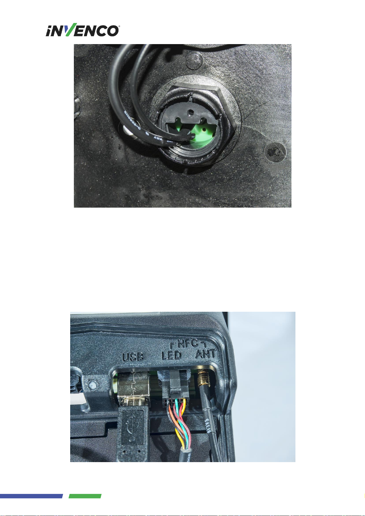
ToBeDetermined REV 00 S2 Manual- OPTIC 12 NFC Installation Guide
Page 5
3 Connection
This document assumes that the NFC will be installed at the same time as both a OPTIC 12 UPC,
OPTIC 12 SDC and a OPTIC 12 APC.
There are two connections to be made from the NFC to the UPC module
1. Insert the 6 way connector, to the socket labled NFC LED.
2. Connect the RF connector to the labled socket NFC ANT.
Page 65

ToBeDetermined REV 00 S2 Manual- OPTIC 12 NFC Installation Guide
Page 6
4 Basic Maintenance
The OPTIC 12 modules are intended for use in the harsh environment of a fuelling station forecourt.
As such they need little maintenance to keep them looking good.
4.1 Cleaning
Use a soft cloth dampened with water for daily cleaning.
If grime builds up, use a diluted mild detergent on a soft cloth.
Take extra care when cleaning the display window:
o Use only a diluted mild liquid soap or detergent and a soft clean cloth.
o Rinse the detergent off carefully using minimal pressure before drying the display
with a clean, dry lint-free or microfiber cloth.
o CAUTION – DO NOT rub the display if it is dry – accumulated dust may scratch the
anti-reflective coating.
CAUTION – Do NOT use petroleum-based solvent cleaners – they may damage surfaces
making the terminal much harder to clean, and shorten the life of the parts.
CAUTION – Do NOT use a high-pressure hose to clean the NFC. The pressure may force
water past seals and that may damage the device.
4.2 Security Checks
The NFC is a transaction-processing device, and will come to the attention of fraudsters. The NFC
must be inspected daily
- for signs of tampering, and
- for any unauthorised devices that may have been attached or overlaid onto the NFC.
If there are any signs of tampering of any kind:
1. Immediately stop the normal operation of the OPTIC 12 system
2. Log a security issue with the support agent’s helpdesk.
3. Take photos of any unauthorised devices or modifications
4. Record details of anyone subsequently interfering with the OPTIC 12 system
4.2.1 Signs of Tampering
Check for the following:
- Damage to, or apparent discoloration of any of the plastic parts
- Any visible wires anywhere on the NFC
- Holes in any surface of the plastic parts.
4.2.2 Attached Devices and/or Overlays
Check for the following:
- If the surfaces of the NFC’s various plastic parts do not line up as they should
- If there are foreign devices attached to the NFC, including inside the cabinet
- If you have a haunting feeling the NFC doesn’t look quite like it should.
Page 66

ToBeDetermined REV 00 S2 Manual- OPTIC 12 NFC Installation Guide
Page 7
5 Drawings
5.1 General arrangement
Page 67

ToBeDetermined REV 00 S2 Manual- OPTIC 12 NFC Installation Guide
Page 8
5.2 Cutout Drawing (do not scale)
Dimensions are in millimetres
© 2016 Invenco Group Ltd. All rights reserved.
No part of this document may be copied or reproduced in any form without prior written consent of Invenco Group Ltd.
The information in this document is subject to change without notice and should not be construed as a commitment by Invenco
Group Ltd. Invenco Group Ltd has taken great effort to verify the accuracy of this document but assumes no responsibility for
any technical inaccuracies or typographical errors.
NEW ZEALAND
Level 2, 7-11 Kawana St
Northcote
Auckland 1145
New Zealand
Ph: + 64 9 369 2935
ASIA
Unit 2B-1-1, Level 1
Block 2B, Plaza Sentral
Jalan Stesen Sentral 5
50470 Kuala Lumpur
Malaysia
Ph: +60 3 2785 1888
 Loading...