

Page 1

G6-300 Installation Guide
DCV-00477 S2 R03
Nov 04 2019
S2 Security Level Guide
No restrictions apply: customer-facing document.
Page 2

Contents
1 Introduction 1
1.1 Where Can the G6-300 be Installed? . . . . . . . . . . . . . . . . . . . . . . . . . . . . . 1
2 Safety & Compliance Information 2
2.1 Preliminary Precautions . . . . . . . . . . . . . . . . . . . . . . . . . . . . . . . . . . . . . 2
3 Safely Accessing a Fuel Pump 3
3.1 Evacuation and Barricading . . . . . . . . . . . . . . . . . . . . . . . . . . . . . . . . . . . 3
3.2 Total Electrical Shut-Off . . . . . . . . . . . . . . . . . . . . . . . . . . . . . . . . . . . . . 3
4 Read the Manual 4
5 Follow the Regulations 5
6 Replacement Parts 6
7 Safety Symbols and Warning Words 7
8 Prevent Explosions and Fires 8
8.1 No Open Flames . . . . . . . . . . . . . . . . . . . . . . . . . . . . . . . . . . . . . . . . . 8
8.2 No Sparks - No Smoking . . . . . . . . . . . . . . . . . . . . . . . . . . . . . . . . . . . . 8
9 Working Alone 10
9.1 Best Practice . . . . . . . . . . . . . . . . . . . . . . . . . . . . . . . . . . . . . . . . . . . 10
9.2 Safety First! . . . . . . . . . . . . . . . . . . . . . . . . . . . . . . . . . . . . . . . . . . . 10
10 Safety First: Working with Electricity 11
11 Hazardous Materials 12
12 Informing Emergency Personnel 13
13 Computer Programs and Documentation 14
14 Approvals 15
14.1 European Directives . . . . . . . . . . . . . . . . . . . . . . . . . . . . . . . . . . . . . . . 15
14.2 FCC . . . . . . . . . . . . . . . . . . . . . . . . . . . . . . . . . . . . . . . . . . . . . . . . 16
15 Product Features 17
15.1 Location of Features . . . . . . . . . . . . . . . . . . . . . . . . . . . . . . . . . . . . . . . 17
16 Accessories in the box 19
DCV-00477 S2 R03 i
Page 3

17 Location of Mounting Points 21
18 Installation 22
18.1 Installing a Brand New OPT . . . . . . . . . . . . . . . . . . . . . . . . . . . . . . . . . . 22
19 Tools Required to Mount the G6-300 26
20 Installing Into a New Pump or Cabinet 27
21 Upgrading an Existing Invenco Outdoor Payment Terminal 29
22 Power Supply Considerations 30
23 Wiring 31
24 Protective Earth 32
25 Ethernet LAN 33
26 DC Power Supply 34
27 Main Power Supply Wiring 35
28 Wiring Completion 36
29 First Power-Up 37
30 Standard Screens 38
31 Basic Maintenance 41
31.1 Cleaning . . . . . . . . . . . . . . . . . . . . . . . . . . . . . . . . . . . . . . . . . . . . . 41
32 How to Load Paper 42
33 Clearing a Paper Jam 44
34 Security Checks 46
34.1 Built in Security . . . . . . . . . . . . . . . . . . . . . . . . . . . . . . . . . . . . . . . . . 46
34.2 Extra Security Checks . . . . . . . . . . . . . . . . . . . . . . . . . . . . . . . . . . . . . . 46
35 Inspection 47
35.1 Key Pad . . . . . . . . . . . . . . . . . . . . . . . . . . . . . . . . . . . . . . . . . . . . . . 47
35.2 Card-Reader Slot and Contactless Reader . . . . . . . . . . . . . . . . . . . . . . . . . . 48
36 Escalation 53
37 Removal & Reinstallation 54
37.1 How to Uninstall a G6-300 . . . . . . . . . . . . . . . . . . . . . . . . . . . . . . . . . . . 54
37.2 How to Reinstall a G6-300 . . . . . . . . . . . . . . . . . . . . . . . . . . . . . . . . . . . 55
38 Drawings 56
38.1 Dimensions . . . . . . . . . . . . . . . . . . . . . . . . . . . . . . . . . . . . . . . . . . . . 56
39 Mounting – New Installation 59
40 Typical Wiring 61
41 Release History 63
DCV-00477 S2 R03 ii
Page 4

CHAPTER 1
Introduction
The G6-300 combines the latest technology with streamlined user-experience, to provide targeted
marketing opportunities that produce both increased revenue and happy customers. We love it and
we know you will too!
The G6-300 is designed to be durable and tough, yet simple and secure to use.
To get the best use out of your G6-300, make sure that it is installed correctly and properly maintained.
This guide will walk you through installation and correct care for your new Outdoor Payment Terminal
(OPT).
Note: If you are installing an OPT using an approved retrofit kit, the instructions with the kit supercede
the instructions in this guide.
1.1 Where Can the G6-300 be Installed?
The G6-300 is a multi-purpose Outdoor Payment Terminal (OPT) designed for unattended use.
It operates in a range of outdoor environments in temperatures from -20C (-4 F) through to +70C (158
F)
It has been primarily designed for fuel station forecourts, but can be installed into any physically secure
cabinet.
This makes it ideal for golf courses, car washes, drive-through’s, sun, sand or snow - anywhere you
want people to pay you but you don’t want to pay someone to stand there and wait to take payments!
Because it’s usually used in fuel stations, this guide explains the requirements for mounting it into a fuel
pump-head, however the steps are applicable to any cabinet.
Specific steps and precautions for pump head installation are highlighted, because we care about you our customers - and your safety.
Please, always use safety precautions when installing our products.
DCV-00477 S2 R03 1
Page 5

CHAPTER 2
Safety & Compliance Information
STOP There are hazards and safety precautions associated with installing, inspecting, maintaining or
servicing this product.
Important: Before you start, READ! You need to understand the safety information in this manual.
Hazards and safety precautions for tasks are always listed.
Fire, explosion or electrical shock could occur and cause death or serious injury if these safe service
procedures are not followed.
2.1 Preliminary Precautions
Fuel stations can be a dangerous place to work - there are flammable fuels, vapours and high voltages.
You should only install, inspect, maintain or service this equipment when you are fully trained and
authorized to do so.
DCV-00477 S2 R03 2
Page 6

Safely Accessing a Fuel Pump
3.1 Evacuation and Barricading
If you need to access a pump/dispenser head, then you must:
• Evacuate all unauthorized persons and vehicles.
• Use safety tape or cones as a barricade to the affected unit(s).
3.2 Total Electrical Shut-Off
CHAPTER 3
Before accessing the electrical components or the electronics of a pump/dispenser, you must carry out
a total electrical shut-off of that unit.
To shut off electricity find the switch or circuit breaker and turn it to the “off” position.
If you can’t turn off the power, STOP. Do not continue until the electricity has been safely turned off by
you or someone else.
DCV-00477 S2 R03 3
Page 7

CHAPTER 4
Read the Manual
Read, understand and follow this manual and any other labels or related materials supplied with this
equipment.
If you do not understand a procedure, call an Invenco authorized service contractor.
Warning: For your own safety and that of others, you must understand the procedures before
beginning work.
DCV-00477 S2 R03 4
Page 8

Regulations exist to keep everyone safe.
You are expected to follow:
• OSH regulations.
• National regulations and codes.
• State regulations and codes.
• Local regulations and codes.
CHAPTER 5
Follow the Regulations
Note: If you do not install, inspect, maintain or service this equipment in accordance with these codes,
regulations and standards, it may affect the safe use and operation of the equipment, or lead to legal
citations with penalties.
DCV-00477 S2 R03 5
Page 9

CHAPTER 6
Replacement Parts
Use only genuine Invenco replacement parts and retrofit kits on your installation.
Using parts other than genuine Invenco replacement parts could create a safety hazard and violate
local regulations.
DCV-00477 S2 R03 6
Page 10

CHAPTER 7
Safety Symbols and Warning Words
Throughout this guide you will see warnings and notes in boxes like below. These are used to let you
know when you need to take extra caution in order to avoid hazards and/or potential injury to yourself
or another person.
Always follow these instructions!
Warning: This alerts you to a hazard or unsafe practice that could result in death or serious injury.
Note: This designates a hazard or unsafe practice which may result in minor injury or a legal issue.
DCV-00477 S2 R03 7
Page 11

CHAPTER 8
Prevent Explosions and Fires
Fuels and their vapours will become explosive if ignited.
All fuels cause vapours when they are exposed to air and transferred between containers; spilled or
leaking fuels cause even more vapours.
When a customer’s tank is filled, vapours leak into the air around the tank and island, and these vapours
can potentially catch fire or explode if they are exposed to a spark or flame.
This is why every single person on a fuel station forecourt must be aware of the danger of sparks and
open flames and take precautions to avoid explosions and fires.
8.1 No Open Flames
Open flames from matches, lighters, welding torches or other sources can ignite the fuel and vapours
present on forecourts.
There should never be an open flame on a fuel station forecourt for any reason.
8.2 No Sparks - No Smoking
Sparks can also start a fire or cause an explosion on a forecourt. Be safety conscious!
Do not:
1. Smoke.
2. Light a match.
3. Use a lighter.
4. Use a mobile phone outside of your car.
5. Start or use power tools.
6. Create a flame of any kind.
Also beware of:
1. Static electricity.
DCV-00477 S2 R03 8
Page 12

G6-300 Installation Guide, DCV-00477 S2 R03
• Always touch the metal of your vehicle after you get out of it to discharge any electrostatic
charge before you approach the dispenser island.
Chapter 8. Prevent Explosions and Fires 9
Page 13

CHAPTER 9
Working Alone
9.1 Best Practice
Always work with at least two people if possible; one to actively work and one as an assistant/backup.
Ideally if you are working around high voltages, the backup/assistant should be trained in providing
Cardiopulmonary Resuscitation (CPR).
9.2 Safety First!
Whether working alone or with someone else:
1. Advise station personnel where you will be working.
2. Warn station personnel not to turn the power back on while you are working on the equipment.
3. Use the OSH tag out and lock out procedures.
• If you are not familiar with this requirement, refer to the information in the service manual and
the OSH documentation.
DCV-00477 S2 R03 10
Page 14

CHAPTER 10
Safety First: Working with Electricity
Always:
1. Use safe and established practices.
2. Follow OSH Lock-Out and Tag-Out requirements before carrying out any service or installation
work.
3. Check all devices before use.
• Is the wiring in good condition?
• Is the grounding connection firmly attached?
• Are all sealing devices and compounds in tact and in place?
Never:
1. Use devices if they have any damage.
2. Skip over safety procedures for any reason.
• Faulty wiring or unsafe procedures can cause a fire, explosion or electrical shock.
Station employees and service contractors must understand and comply with these guidelines
completely to ensure safety while the equipment is down.
DCV-00477 S2 R03 11
Page 15

CHAPTER 11
Hazardous Materials
Some materials present inside electronic enclosures may present a health hazard if not handled
correctly.
• Always wear gloves if practical to do so.
• Keep your hands away from your eyes and mouth during installation.
• Wash your hands as soon as possible.
DCV-00477 S2 R03 12
Page 16

Informing Emergency Personnel
Emergency personnel will need the following information:
• Location of accident (e.g. address, front/back of building).
• Nature of accident (e.g. possible heart attack, run over by car, burns).
• Approximate age of victim (e.g. baby, teenager, middle-age, elderly).
• Whether or not victim has received first aid (e.g. stopped bleeding by pressure).
• Whether or not victim has vomited (e.g. if swallowed or inhaled something).
CHAPTER 12
Warning: Oxygen may be needed at scene if gasoline has been ingested or inhaled. Seek medical
advice immediately.
DCV-00477 S2 R03 13
Page 17

CHAPTER 13
Computer Programs and Documentation
All Invenco Group Ltd. computer programs (including software on discs and within memory chips) and
documentation are copyrighted by, and shall remain the property of, Invenco Group Ltd. Such computer
programs and documents may contain trade secret information.
The duplication, disclosure, modification, or unauthorized use of computer programs or documentation
is strictly prohibited unless otherwise licensed by Invenco Group Ltd.
DCV-00477 S2 R03 14
Page 18

CHAPTER 14
Approvals
Invenco develops and maintains its hardware and software products using industry-standard quality
processes, and is audited by the MasterCard TQM (Terminal Quality Management) scheme.
The G6-300 OPT has the following approvals:
• TQM (Quality)
• PCI (Payment Card Industry)
• EMV standards (Security)
• EN 55032 (Emissions)
• EN 55024 (Immunity)
• EN 300 300 & ETSI 301 489-3 (in conjunction with ETSI 301 489-1) for Radio
• FCC certification (Part 15.225, 15.207 transmitter)
• IC certification (RSS-Gen Issue 5 section 8.8 & RSS-210 Issue 9 Section B.6)
• IEC/EN/UL 62368-1 (Safety – Audio/video, information and communication technology equipment)
• UL 121201 (Hazardous location safety – Class I Division 2)
14.1 European Directives
The G6-300 complies with the necessary European Directives for the CE mark.
DCV-00477 S2 R03 15
Page 19

G6-300 Installation Guide, DCV-00477 S2 R03
14.2 FCC
FCC ID: 2AC7B-G6300OPT
This device complies with part 15 of the FCC Rules. Operation is subject to the following two conditions:
1. This device may not cause harmful interference, and
2. This device must accept any interference received, including interference that may cause
undesired operation.
Note: The grantee is not responsible for any changes or modifications not expressly approved by
the party responsible for compliance. Such modifications could void the user’s authority to operate the
equipment.
Note: This equipment has been tested and found to comply with the limits for a Class B digital device,
pursuant to part 15 of the FCC Rules. These limits are designed to provide reasonable protection
against harmful interference in a residential installation. This equipment generates, uses and can
radiate radio frequency energy and, if not installed and used in accordance with the instructions, may
cause harmful interference to radio communications. However, there is no guarantee that interference
will not occur in a particular installation. If this equipment does cause harmful interference to radio
or television reception, which can be determined by turning the equipment off and on, the user is
encouraged to try to correct the interference by one or more of the following measures:
• Reorient or relocate the receiving antenna.
• Increase the separation between the equipment and receiver.
• Connect the equipment into an outlet on a circuit different from that to which the receiver is
connected.
• Consult the dealer or an experienced radio/TV technician for help.
Chapter 14. Approvals 16
Page 20
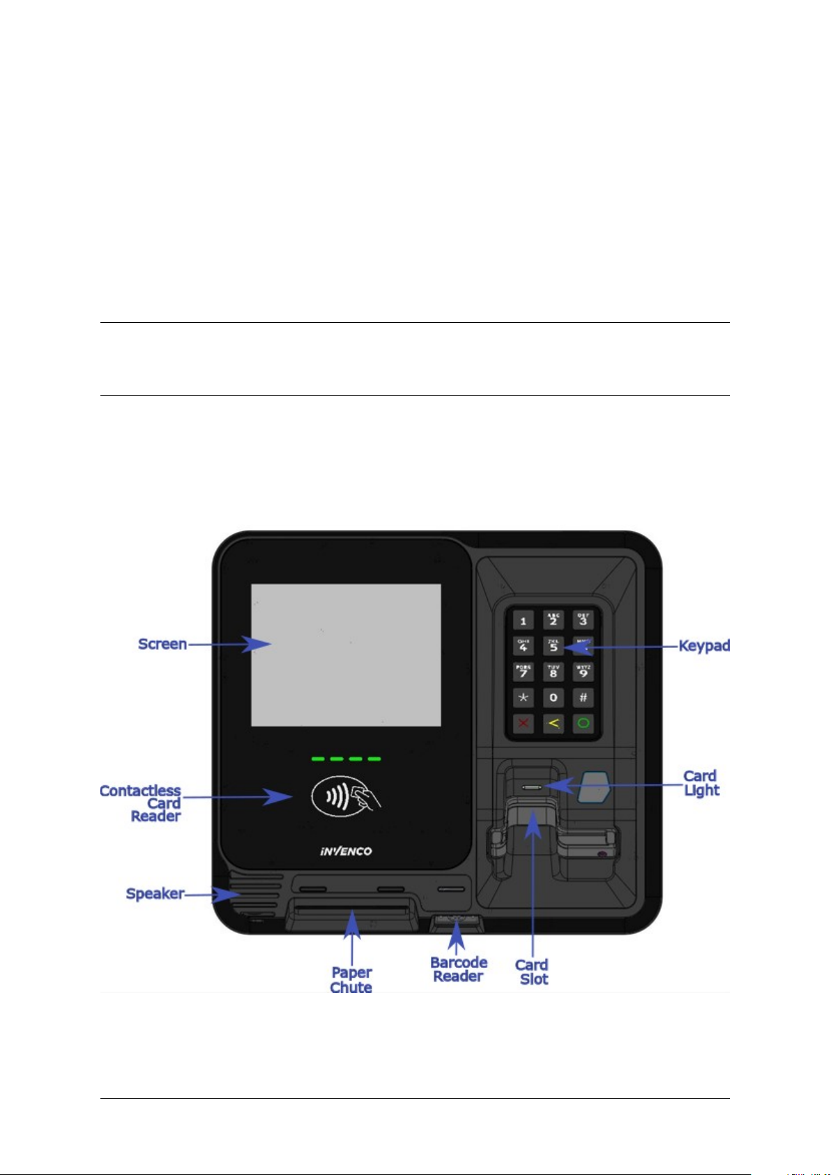
15.1 Location of Features
CHAPTER 15
Product Features
Fig. 15.1: G6-300 Front Features
DCV-00477 S2 R03 17
Page 21
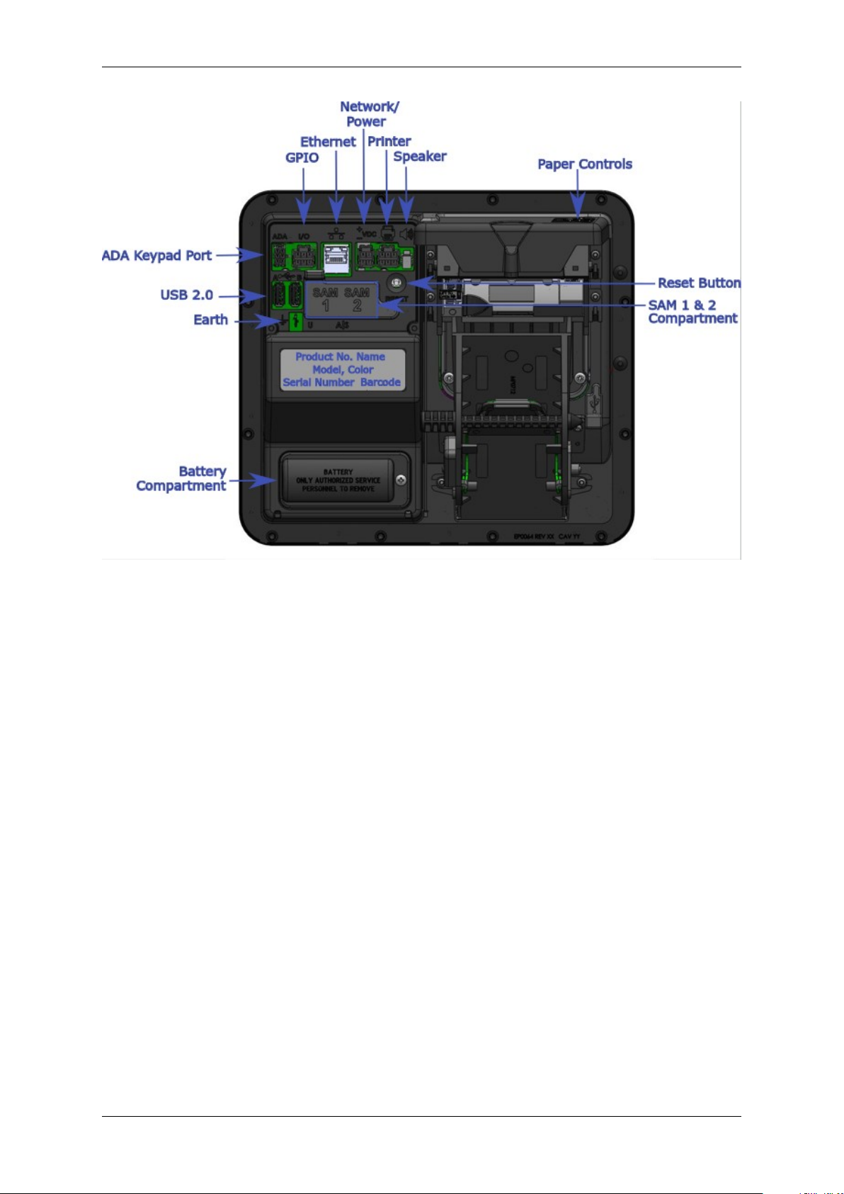
G6-300 Installation Guide, DCV-00477 S2 R03
Fig. 15.2: G6-300 Rear Features
Chapter 15. Product Features 18
Page 22

Accessories in the box
Inside the box is a small plastic bag that contains a spindle and a gasket.
CHAPTER 16
Fig. 16.1: Accessories bag
DCV-00477 S2 R03 19
Page 23

G6-300 Installation Guide, DCV-00477 S2 R03
Fig. 16.2: Spindle to hold printer paper
Fig. 16.3: Gasket for mounting G6-300 to pump head
Chapter 16. Accessories in the box 20
Page 24

Location of Mounting Points
Green highlights show the standard mounting points for a new installation.
See the Drawings at the end of this guide for panel cut-out information.
CHAPTER 17
Fig. 17.1: Location of mounting points (in green).
DCV-00477 S2 R03 21
Page 25

CHAPTER 18
Installation
18.1 Installing a Brand New OPT
In most cases a new installation must be done by the pump manufacturer, not a third party. Each pump
has safety certifications that can be invalidated if anyone other than the manufacturer modifies it.
Before a G6-300 can be installed, the pump enclosure must meet the following standards:
1. Fire. The enclosure must be designed to meet the requirements of ISO/EN 60950-1 for fire
enclosures.
2. ATEX (Explosive Atmospheres).
The G6-300 has openings that prevent it being gas-tight. Because of this, it should be installed
away from all hazards. Refer to local laws and regulations for hazardous zones to work out the
best mounting place for the G6-300. The pump or cabinet that the G6-300 is mounted in should
also be designed to prevent a dangerous build-up of explosive gases.
3. Security.
The pump or cabinet should offer physical security to protect the public from the hazards within,
and to reduce the ability of anyone to tamper with the OPT.
4. Power & Data.
a. The pump or cabinet must provide mains power. The requirements are:
i. A permanently-wired connection or a socket to plug it into.
ii. A protective earth connection.
iii. The outlet may be switched if it is a socket, and must be switched if it is permanently
wired.
iv. We recommend one Power Supply Unit (PSU) per G6-300. The use of two G6-300s on
a single PSU may lead to erratic start up behaviour and is not recommended. If using
two G6-300s to one PSU, both must have power applied at the same time to reduce this
risk.
b. The pump or cabinet must provide an Ethernet data connection. The requirements are:
v. Capable of at least 10Mbps (preferably 100Mbps).
DCV-00477 S2 R03 22
Page 26

G6-300 Installation Guide, DCV-00477 S2 R03
vi. The connection must be either a socket into which a standard Ethernet patch cable can
be connected, or a cable that is terminated in a standard RJ45 plug suitable for direct
connection into the OPT LAN socket.
vii. Minimum cable standard should be Cat5e.
c. The enclosure may provide an alternative data connection for terminals that have optional
communications modules installed. Please consult with Invenco for what options are
available.
5. Accessibility.
The enclosure must be designed and mounted so that disabled persons are able to operate the
OPT. Height must be compliant with PCI 5.0 standards. The G6-300 has an optional ADA keypad
that can be purchased and installed if required in order to meet this compliance.
6. Materials.
The enclosure and all its components must be constructed of durable materials suitable for the
intended location.
7. Door cut-out.
d. Use the wireframe §38 Drawings at the end of this manual to determine the extra space
required for the front of the terminal (the terminal is larger than cut-out).
e. The edge of the cut-outs should be smooth and free of burrs, and the surface of the door
around the cut-out should be clean, and planar within ± 1mm.
8. Water-Tightness.
The G6-300 is rated for IP24 on its external parts.
The parts sitting inside the pump/pedestal enclosure are designed to reduce the likelihood of rain
splashes entering the electronics but the enclosure must provide good protection from water.
The door should have a water seal against the enclosure, and there should be good drainage
and/or a system to reduce excessive condensation build-up and dripping.
9. Protection from Weather Extremes. | While the G6-300 is intended for use outdoors, exposure
to direct sunlight and/or heavy rain can affect customers’ experience using the product. | The
pump or enclosure should provide a canopy that prevents the OPT from being exposed to direct
sunlight and heavy rain. | If the OPT cannot be protected from direct sunlight, a warning sign
should be provided close to the OPT advising that the screen may become too hot to touch.
10. Placement.
The G6-300 must always be installed in an upright (vertical) position with no horizontal tilt.
11. Hinging.
Use the following diagrams as a guide when designing an enclosure and/or door to house the
G6-300. This will ensure there is a clearance between the G6-300 housing and the opening.
Note: Invenco Recommends Right-side hinging only. Hinging on the left side may cause
cables to be pulled out.
Chapter 18. Installation 23
Page 27

G6-300 Installation Guide, DCV-00477 S2 R03
Hinging Option 1
For models without an internal printer, or for models with a printer where the paper has been mounted
with the spindle moving right to left through the paper roll (with the point to the center of the terminal):
Fig. 18.1: G6-300 Side hinging diagram, spindle pointed left or with no printer.
Hinging Option 2
For models with an internal printer, where the paper has been mounted with the spindle moving left to
right through the paper (with the point ending by the right side of the terminal):
Fig. 18.2: G6-300 Side hinging points diagram, spindle pointed left.
Chapter 18. Installation 24
Page 28

G6-300 Installation Guide, DCV-00477 S2 R03
Hinging Option 3
Top and bottom hinging points, suitable for all models.
Fig. 18.3: G6-300 Top-bottom hinging diagram.
Chapter 18. Installation 25
Page 29

CHAPTER 19
Tools Required to Mount the G6-300
• 12 x M4 screws of the correct length to attach the OPT to your pump/cabinet.
• A screw driver to fit the M4 screws.
• Philips #1 or Flat 5mm screw driver - for connections on the power supply.
• Small adjustable spanner - for earth connections inside the cabinet.
• Cable ties.
• Side cutters - to trim the cable tie(s).
• You may require other tools if retrofitting into a non-standard enclosure.
Warning: Do not use power tools if working on a fuel station forecourt. Any spark could cause a
fire or explosion.
DCV-00477 S2 R03 26
Page 30

CHAPTER 20
Installing Into a New Pump or Cabinet
Fig. 20.1: Installing a New G6-300
DCV-00477 S2 R03 27
Page 31

G6-300 Installation Guide, DCV-00477 S2 R03
Fig. 20.2: How to Attach the Gasket
Chapter 20. Installing Into a New Pump or Cabinet 28
Page 32

CHAPTER 21
Upgrading an Existing Invenco Outdoor Payment Terminal
The G6-300 is designed to fit into the existing cut-out created for an earlier G6 model to allow for an
easy upgrade.
It will also fit onto legacy upgrade kits for those customers who have upgraded in the past from a G5 to
a G6 OPT.
DCV-00477 S2 R03 29
Page 33

CHAPTER 22
Power Supply Considerations
The G6-300 has been certified using a one-to-one ratio of G6-300 to power supply unit. All other
configurations are not certified.
DCV-00477 S2 R03 30
Page 34

Three connections need to be made to the G6-300:
1. Protective Earth.
2. Ethernet LAN.
3. DC Power supply.
The DC power supply cable also needs to be connected to the power supply.
CHAPTER 23
Wiring
DCV-00477 S2 R03 31
Page 35

CHAPTER 24
Protective Earth
The G6-300 is provided with an Earth Tab and is recommended to be earthed.
The tab must be connected to the pump (or cabinet) frame to provide protection from both power faults
and static discharges. The earth wire must be minimum 1.5mm and both it and the earth stud must
meet local regulations.
DCV-00477 S2 R03 32
Page 36

CHAPTER 25
The Ethernet cable is plugged into the correct connector on the rear of the G6-300:
Ethernet LAN
Fig. 25.1: Ethernet connection
DCV-00477 S2 R03 33
Page 37

CHAPTER 26
DC Power Supply
The low-voltage DC Cable is plugged into the correct connector on the rear of the G6-300:
Fig. 26.1: Low-voltage DC cable
DCV-00477 S2 R03 34
Page 38

CHAPTER 27
Main Power Supply Wiring
The other end of the low-voltage DC Cable is connected into the AC-DC power supply:
Warning: Once all the wiring to the power supply terminals has been completed, install the terminal
cover to prevent accidental contact with the live mains connections
DCV-00477 S2 R03 35
Page 39

CHAPTER 28
Wiring Completion
When all the cables have been installed, use cable ties to provide strain relief.
Ensure that all cables are tidy and cannot become snagged or pinched when the door of the cabinet is
opened and closed.
Warning: Local regulations may also require that the installation is electrically tested and certified
BEFORE switch-on.
DCV-00477 S2 R03 36
Page 40

CHAPTER 29
First Power-Up
Once the installation is complete and the wiring is certified (if necessary), the main power can be
switched on.
The G6-300 takes a couple of minutes to complete its start-up phase.
During this, several standard information screens will display.
There may be other screens as well, depending on customer configuration.
DCV-00477 S2 R03 37
Page 41

Start up screen:
CHAPTER 30
Standard Screens
Fig. 30.1: G6-300 Start up screen.
DCV-00477 S2 R03 38
Page 42

G6-300 Installation Guide, DCV-00477 S2 R03
Connecting to ethernet screen:
Fig. 30.2: Trying to establish ethernet connection.
Chapter 30. Standard Screens 39
Page 43

G6-300 Installation Guide, DCV-00477 S2 R03
When the terminal has successfully connected to the Ethernet LAN it will display the following screen:
Fig. 30.3: Ethernet connection established.
If the Ethernet LAN is not operational the terminal will display this screen instead:
Fig. 30.4: Ethernet connection not established.
After this the start-up will continue with the screens changing depending on individual customer
configuration.
Chapter 30. Standard Screens 40
Page 44

31.1 Cleaning
The G6-300 is designed to be low maintenance.
Daily cleaning:
Wipe with a soft damp cloth using only water.
If dirt or grime builds up:
• Use a diluted mild detergent and wipe with a soft cloth.
CHAPTER 31
Basic Maintenance
• Dry the screen using a lint-free or microfiber cloth.
Things to watch out for:
• Always clean off excess detergent.
• Do not use a high pressure water stream to clean your G6-300. Water pressure may damage the
card reader or printer chute.
• Do not rub the display if it is dry - dust or dirt can scratch the anti-reflective coating.
• Do not use petroleum based solvent cleaners, they will damage the surface and shorten the life of
your product.
• Over time the printer may build up dust and/or debris from the paper cutting function. Please do
not clean this yourself - refer cleaning to a qualified service agent.
DCV-00477 S2 R03 41
Page 45

CHAPTER 32
How to Load Paper
DCV-00477 S2 R03 42
Page 46

G6-300 Installation Guide, DCV-00477 S2 R03
Fig. 32.1: How to Load Paper.
Chapter 32. How to Load Paper 43
Page 47

CHAPTER 33
Clearing a Paper Jam
If you need to clear a paper jam, remember:
• Don’t use anything sharp - it could damage the printer.
• Be gentle. If you take the paper roll out, you should be able to see where the paper is jammed
and free it with a little bit of patience and a gentle touch.
• Any damage done to the printer while clearing a paper jam is not covered by warranty.
DCV-00477 S2 R03 44
Page 48

G6-300 Installation Guide, DCV-00477 S2 R03
Fig. 33.1: How to clear a paper jam.
Chapter 33. Clearing a Paper Jam 45
Page 49

CHAPTER 34
Security Checks
34.1 Built in Security
The G6-300 has built-in tamper detections, but you should also regularly check your G6-300 for signs
of tampering or alteration.
If it looks different to normal, then there could be a hidden camera or PIN-disclosing bug - you might
have a problem that thereatens customer security.
34.2 Extra Security Checks
Use this section to carry out extra security checks, and if you’re still not sure about your G6-300 then
call Customer Support.
The following pages include photos and descriptions of what the G6-300 components should look like.
If your G6-300 looks different in any way , DO NOT use it.
Follow the escalation procedure in §36 Escalation if you have any doubts at all about the integrity of
your OPT.
DCV-00477 S2 R03 46
Page 50

CHAPTER 35
Inspection
The G6-300 has a smooth finish with an uninterrupted surface. Any breaks or uneven surfaces should
be inspected as a potential security concern.
35.1 Key Pad
1. The G6-300 keypad has a matt black surround with matt key tops.
• The key-tops are back-lit.
• The numbers must be illuminated when the key-pad is active.
– If the numbers don’t light up when the key-pad is active, then check the key-pad for
signs of tampering or an overlay.
2. The matt black surround is a flush mount to the G6-300 front fascia.
• If it appears not to be flush with the front fascia surface, check to see why.
3. The key-pad privacy shield is a smooth, uninterrupted surface, and should be inspected for uneven
surfaces, cracks or holes that could be as a result of a PIN disclosing camera being placed on/into
the OPT.
DCV-00477 S2 R03 47
Page 51

G6-300 Installation Guide, DCV-00477 S2 R03
Fig. 35.1: Example of keypad and privacy shield.
35.2 Card-Reader Slot and Contactless Reader
What to check for:
• Are there any wires of any kind coming out of the Card Slot?
Chapter 35. Inspection 48
Page 52

G6-300 Installation Guide, DCV-00477 S2 R03
– There should be no visible wires at all on or around the Card Slot.
• Is the OPT finish uninterrupted and consistent across the Card Slot?
– There should be no cracks, holes or bumps of any kind.
• Does the card slot acceptor light:
– Flash green when it is ready and waiting to accept a card?
– Turn red when a card is inserted and a transaction is processing?
– Turn blue only when the card can be safely removed?
• Does the Contactless Reader:
– Show one steady green light when ready to accept a payment?
Note: Remember, if your G6-300 does not look or act like it should, do not use it. Contact Invenco
immediately for further assistance.
Fig. 35.2: Front of card slot.
Chapter 35. Inspection 49
Page 53

G6-300 Installation Guide, DCV-00477 S2 R03
Fig. 35.3: Card slot insertion light.
Chapter 35. Inspection 50
Page 54

G6-300 Installation Guide, DCV-00477 S2 R03
Fig. 35.4: Left hand close-up of card slot.
Chapter 35. Inspection 51
Page 55

G6-300 Installation Guide, DCV-00477 S2 R03
Fig. 35.5: Right hand close-up of card slot.
Chapter 35. Inspection 52
Page 56

CHAPTER 36
Escalation
If you think that your G6-300 has been tampered with:
• Contact the vendor’s security person or support desk immediately.
• If neither of those contacts are available, contact Invenco’s security officer at the Auckland address
detailed at the end of this document.
• Notify local law-enforcement immediately.
DCV-00477 S2 R03 53
Page 57

37.1 How to Uninstall a G6-300
CHAPTER 37
Removal & Reinstallation
Fig. 37.1: Instructions for Uninstalling a G6-300.
DCV-00477 S2 R03 54
Page 58

G6-300 Installation Guide, DCV-00477 S2 R03
37.2 How to Reinstall a G6-300
Fig. 37.2: Instructions for Reinstalling a G6-300.
Chapter 37. Removal & Reinstallation 55
Page 59

38.1 Dimensions
CHAPTER 38
Drawings
Fig. 38.1: G6-300 Front Dimensions.
DCV-00477 S2 R03 56
Page 60

G6-300 Installation Guide, DCV-00477 S2 R03
Fig. 38.2: G6-300 Side Dimensions.
Chapter 38. Drawings 57
Page 61

G6-300 Installation Guide, DCV-00477 S2 R03
Fig. 38.3: G6-300 Rear Dimensions & Mounting Points.
Chapter 38. Drawings 58
Page 62

CHAPTER 39
Mounting – New Installation
Fig. 39.1: Mounting guide - NOT TO SCALE. Do not use as a template.
DCV-00477 S2 R03 59
Page 63

G6-300 Installation Guide, DCV-00477 S2 R03
Fig. 39.2: Exploded view, mounting to panel.
Chapter 39. Mounting – New Installation 60
Page 64

The next page shows the standard and typical wiring for the G6-300.
We recommend that you use this wiring for safety and correct performance.
CHAPTER 40
Typical Wiring
DCV-00477 S2 R03 61
Page 65

G6-300 Installation Guide, DCV-00477 S2 R03
Fig. 40.1: Typical G6-300 wiring.
Chapter 40. Typical Wiring 62
Page 66

CHAPTER 41
Release History
Version Prepared by Date Change description
1.0 Kristy Clarkson 20190904 Created document.
2.0 Kristy Clarkson 20191025 Revision of images
3.0 Kristy Clarkson 20191105 Addition of further
approvals
DCV-00477 S2 R03 63
Page 67

NEW ZEALAND
Level 2, 7-11 Kawana St
Northcote
Auckland 0627
New Zealand
Ph: +64 9 905 5600
NORTH AMERICA
Building 100, Windward Chase
1235 Old Alpharetta Rd, Suite 130
Alpharetta
Georgia 30005, USA
Ph: +1 470 253 7568
ASIA
Level 3, Wisma Ali Bawal 1
Jalan Tandang
46050 Petaling Jaya
Selangor, Malaysia
Ph: +60 3 7781 0298
EUROPE
6th Floor, White Building
1 - 4 Cumberland Place
Southampton
SO15 2NP
United Kingdom
Ph: +44 23 8022 7645
©2019, Invenco Group Ltd. All rights reserved.
No part of this document may be copied or reproduced in any form without the prior written consent of
Invenco Group Ltd.
The information in this document is subject to change without notice and should not be construed as
a commitment by Invenco Group Ltd. Invenco Group Ltd has made all reasonable efforts to verify the
accuracy of this document but assumes no responsibility for any technical inaccuracies or typographical
errors.
 Loading...