

invebo BC7A Installation Instructions Manual
invebo BC7A
Installation Instructions
Installation of the Bluetooth BC7A
Upgrade KIT in Bose SoundDock
Original Series 1
The installation of the board can be carried out
without any previous experience.
Overview:
Fitting the BC7A kit Replacement is relatively
straight forward but like everything the first time is
more difficult and some may find it extremely fiddly.
These instructions are to show the method of
replacing the BC7A in a detailed step by step
procedure. The Bose SoundDock is still the best
sounding and most affordable compact speaker
around and one of the few things that can’t be
upgraded by going out and buying a better sounding
unit at reasonable cost.
Note the BC7A has the 30-pin legacy iPod docking
connector with USB charge mode support,.
Which docks are compatible?
The BC7A kit is designed to work with all Bose
SoundDock Series 1. If your dock serial number
does not start in digits 0357 or 0402 or 0498 or
052398 then the BC7A is not compatible with your
dock.
Before you Start: It is a good idea to watch the
detailed ‘how to’ videos on YouTube. A full step-bystep video version of these BC7A instructions is
available in the technical guide section of our
website. See the Technical Guides section at
www.invebo.com
For a problem free installation watch the full BC27A
Instruction procedure on YouTube:
https://www.youtube.com/watch?v=hwA8buY7qSc
Tools Required:
1. T8 Torx Driver (from Kit)
2. Sharp craft knife
3. Pliers (flat nose)
General:
1.
The full kit contains the T8 Torx screw
driver, BC7A Main Board.
2.
Initially it is not necessary to remove the
four larger cross-head screws holding the
base moulding on. The half moon moulding
can be removed whilst all of these four
screws are tight.
3.
Three T8 screws hold the dock assembly in
place. These are found on the underside of
the half-round front moulding where the
IPod plugs in. Once removed the assembly
can be pulled out from underneath. You do
this by gently carefully pulling the ribbon
cable which is tucked under the lower cover.
Pull it out so that about 1.5 to 2 inches (3 to
5cm) of ribbon is showing. Then hold onto
the cable to prevent it coming out any
further and pull it from the plug on the
docking board.
4.
You should now have the docking
assembly, including the board and the
plastic moulding, free in your hand. Put the
body of the dock to one side.
5.
Separation of the dock board from the base
moulding requires some sharp flush side
cutters or a sharp craft knife and a great
deal of care. Carefully peel off the black
plastic overlay and put it aside.
6.
You should now see the docking board and
the tops of the plastic pegs that hold the
board in position. These are small pegs that
have been heat-staked. This means that at
the Bose factory the tops of the pegs have
been melted into a mushroom shape.
7.
The head of the mushroom is what holds
the board in place. It is necessary to
carefully cut the tops of the mushrooms with
your sharp craft knife or flush-cutting side
cutters. Trim the mushroom heads back until
the smaller diameter of the body of the peg
is visible, equivalent to roughly the diameter
of the hole in the PCB.
8.
Check that you have done all the pegs.
Then docking PCB can now be gently
levered away from the moulding.
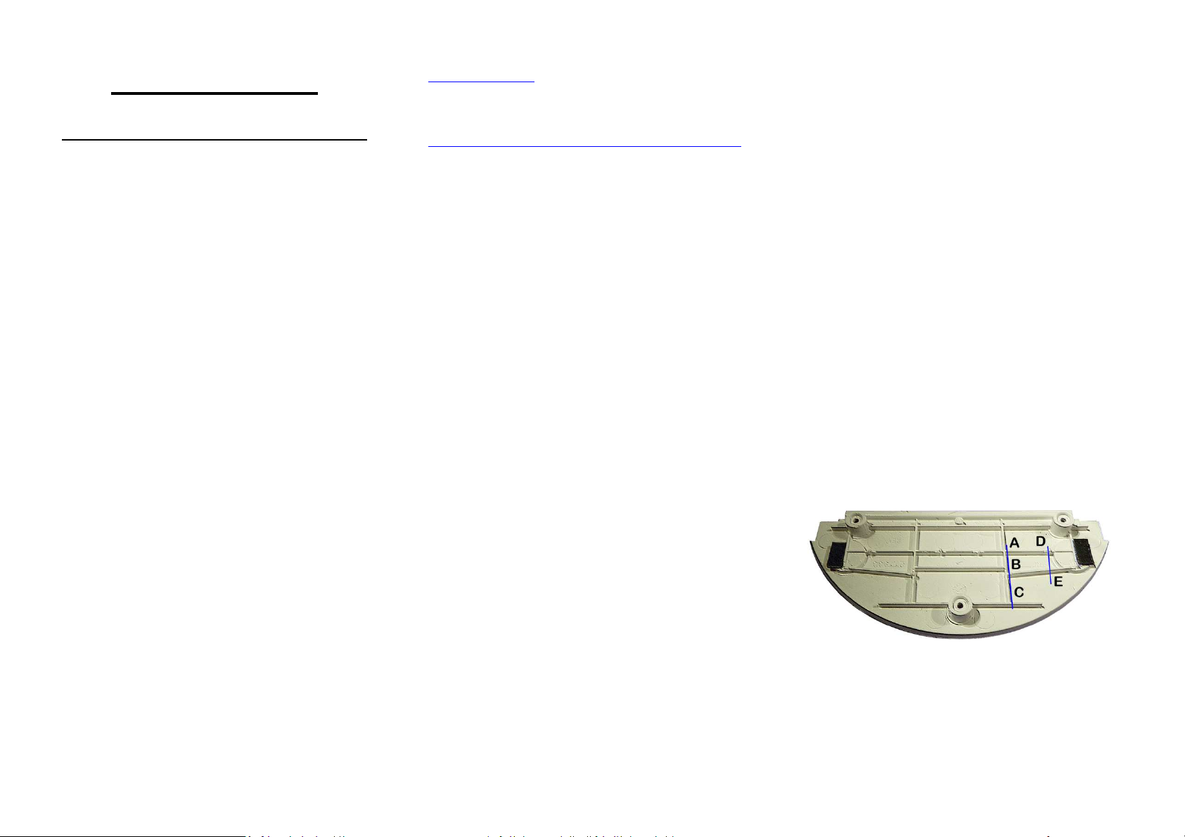
9.
Modification of the Molding: It is
necessary to remove three plastic ribs to
accommodate the electronics module
located on the underside of the BC7A. It is
recommended that you refer to the YouTube
instruction video referenced at the top of

these instructions. . Using the craft knife
make vertical cuts through the horizontal
ribs at A, B C, D. The cut must be through
the full height of the ribs. The position of the
cuts s denoted by the lines on the diagram.
Grip the section of rib between A and D with
flat nosed pliers and Twist to remove this
section of rib. Repeat to remove section B
to E. Repeat the remove the short spar to
the right of C. The root of the removed ribs
must be level with the flat surface of the
molding. If necessary trim of any remnants of the
ribs with the craft knife.
10.
Take the BC7A controller board in your
hand and have a look at it. Notice the ribbon
connector at the edge of the board. See that
there is a small darker section at each end
that can be moved back and forth. This is
the locking mechanism.
11.
Using your fingernail ensure that the
locking mechanism is out at both ends of
the connector. In the out position the tabs
are about 0.08” (2mm) out from the home
position.
12.
If the locking mechanism isn’t in the open
position then the ribbon cannot be inserted.
The insertion force is near to zero when it is
correct. If you have to push to get the ribbon
into the connector then check the lock
mechanism is out at both ends.
13.
A supported foam overlay is supplied with
the kit. Remove the backing from the
adhesive strips and place the overlay over
the docking connector, align and press the
strips so that they adhere to the top of the
docking board.
14.
Place the BC7A board over the pegs and
push down onto the half-moon moulding.
Usually the mushroom heads are an
interference fit which will hold the board in
position. You might even feel it click into
place.
15.
IMPORTANT: Make sure that the board is
sitting flush with the supporting ribs on the
base moulding. If the board is suspended on
the mushroom heads of the pins then you
could have problems with the volume
controls buttons as they will sit too high and
may spontaneously alter the volume. Check
that step 9 has been done correctly noting
that the electronics on the underside of the
BC7A are clear of the removed ribs. Look at
it from the side and make sure that there is
no gap between the board and the
supporting parts of the moulding. If there are
small gaps then simply make sure that the
board moves freely down onto the moulding
with little finger pressure.
16.
Ensure that the board is sitting down flat.
17.
Hold the dock so that the base is horizontal
and uppermost. Loosen the four cross head
screws about one turn each. DO NOT
REMOVE the screws completely.
18.
Bend the ribbon cable backwards so that
the end is parallel to and lying over the flat
base moulding.
19.
Hold the half moon dock assembly with the
base flat on the lower base of the dock.
You will see that when plugged in the half
moon will flip 180 degrees and be in the
correct orientation to be refitted.
20.
Ensure that the ribbon connector locking
tabs/bar are in the fully out position
(unlocked). Feed the end of the ribbon cable
into the connector and when fully engaged
and it is exiting perpendicular to the
connector, push the locking tabs into the
engaged position. You can use your
fingernail. Note that moderate force is
required to do this and it is necessary
engage each side more than once.
Sometimes the other end pops out slightly
when you push the other end in.
21.
When the locking mechanism is fully
engaged, give the ribbon cable a gentle tug
to ensure that the ribbon is securely held in
the connector. You should see a line of 24
bright tin contacts protruding an equal
distance of approximately 1 millimetre out of
the connector. If you can see more at one
end than the other then the ribbon is not
correctly inserted.
22.
Note that if for any reason you want to
unplug the ribbon, you must first disengage
the locking mechanism to let the ribbon slide
out with zero force.
23.
Test fit the BC7A on the support moulding
by placing over the pegs. Look between the
underside of the board and the support ribs
to ensure that there is no gap. i.e. The
board is sitting right down on the support
webs of the half moon base moulding.
24.
During the next operation you must ensure
that the BC7A controller PCB stays located
on the pegs. Be careful. If you have cut the
mushrooms just right then it will snap on
and hold in place nicely. If not it may be a
 Loading...