

Page 1
1
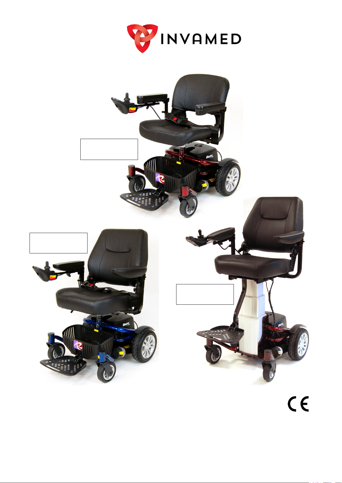
Reno Elite User Manual
P325/CS –
Captain Seat
P325/RS –
Rising Seat
P325 –
Standard Seat
Please ensure that this user manual is read and understood before using
the powerchair.
Page 2

2
Contents
Page
Introduction
3
Intended Use
3
Technical Specifications
3
Feature Guide
4
Safety Advice
5
Adjustments
6-9
⇒ Seat Height
6
⇒ Lap Belt
6
⇒ Flip-up Footplate Height
6
⇒ Seat Swivel & Removal
7
⇒ Arm Width
8
⇒ Flip-up Armrest Angle Adjustment
8
⇒ Joystick Depth
9
Brake Release / Freewheel Operation
9
Battery
10-11
⇒ Removal
10
⇒ Charging
10
⇒ Pack
11
⇒ Disposing & Recycling
11
Operating The Powerchair
12-14
⇒ Moving Off & Steering
12
⇒ Reversing
12
⇒ P325 & P325/CS Joystick Controller
12
⇒ P325/RS Joystick Controller
13
⇒ ‘Lock’ Function For All Model Controllers
13
⇒ Drop Kerb Climbing
14
⇒ Drop Kerb Descent
14
⇒ Reaching & Stretching
14
Disassembly & Reassembly
15-16
⇒ Disassembly
15
⇒ Reassembly
16
Transportation
17
Maintenance
18-19
⇒ Cleaning
18
⇒ Storage & General Care
18
⇒ Routine Maintenance
18
⇒ Circuit Breaker
18
⇒ Problem Checklist
19
⇒ Joystick Error Codes
19
Further Information
20
⇒ General Use
20
⇒ Driving In Pedestrian Areas
20
⇒ Weather & Outdoor Conditions
20
⇒ Health Factors
20
⇒ Product Stability
20
⇒ Safety Information Regarding Electromagnetic Interference (EMI)
20
Warnings
21-22
Warranty Terms & Conditions
23
Notes
24
Page 3
3
Introduction
Dimensions - P325 & P325/CS
Total Length
880mm / 35”
Total Width
600mm / 24”
Height (Seat Removed)
460mm / 18”
20-22”
P325
Backrest)
36-37”
Seat Width
440mm / 17”
Seat Height (Backrest Height)
390mm / 15”
Seat Depth
400mm / 16”
P325/CS
Backrest)
/
40-41”
Seat Width
460mm / 18”
Seat Height (Backrest Height)
490mm / 19”
Seat Depth
430mm / 17”
Dimensions - P325/RS
Total Length
880mm / 35”
Total Width
600mm / 24”
Height (Seat Removed)
415mm / 16”
21-32”
Backrest)
/
44-55”
Seat Width
460mm / 18”
Seat Height (Backrest Height)
490mm / 19”
Seat Depth
430mm / 17”
General Specification
Battery Charger
2 A
Max. Speed
6kmph / 4mph
Component Weights - P325 & P325/CS
Front Chassis
14 kg / 2st 2lb
Front Chassis
26.5 kg / 4st 2lb
Seat – P325/RS
16.5 kg / 2st 8lb
Overall Weight – P325/RS
79.5 kg / 12st 7lb
Caution:
Persons with lower body amputations should not use this device unless evaluated
with artificial limbs fitted, as stability may be compromised due to
irregular centre of gravity.
Thank you for your purchase of the Reno Elite powerchair. This powerchair incorporates the latest
innovative designs and can be used in confined spaces both indoors and out. The Reno Elite
powerchair can be easily dismantled without tools which enables it to be stored in the boot of a
vehicle or stored neatly in an indoor location. The detachable battery pack allows convenient
charging wherever necessary.
Intended Use
The Reno Elite was carefully designed for indoor or outdoor use in paved pedestrian areas by a
single individual with limited mobility weighing up to a maximum of 136kg (21st 5lb). Your supplier/
healthcare professional will determine the suitability of the powerchair for your intended use.
an
Technical Specification
Class 1 Medical Device (according to Medical Devices Regulation (EU) 2017/745)
Class 2 Invalid Carriage (according to the Highway Code)
Battery 21-22Ah
Maximum User Weight 136kg / 21st 5lb
Range*
Turning Radius 550mm / 21.6”
Safe working slope 6º
see note below
20km / 12miles
Height (Floor To Seat) 520-560mm /
Overall Height (Floor To Top Of
Battery Pack 14 kg / 2st 2lb
Rear Chassis 22 kg / 3st 6lb
Seat – P325 11kg / 1st 10lb
Seat – P325/CS 16.5 kg / 2st 8lb
Overall Weight – P325 61 kg / 9st 8lb
Overall Weight – P325/CS 66.5 kg / 10st 6lb
Overall Height (Floor To Top Of
910-950mm /
1010-1050mm
Component Weights - P325/RS
Battery Pack 14 kg / 2st 2lb
Rear Chassis 22.5 kg / 3st 7lb
Height (Floor To Seat) 540-820mm /
Overall Height (Floor To Top Of
*Passenger weight, rough ground conditions, low
temperatures and battery condition can affect maximum
range.
1130-1410mm
Page 4
4
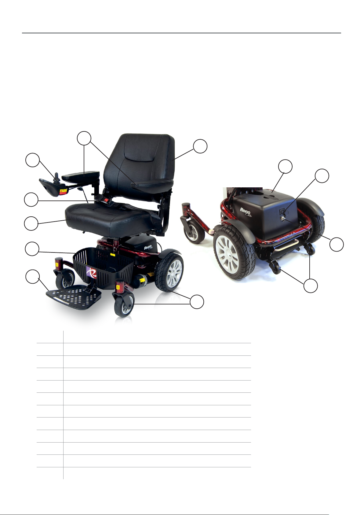
Feature Guide
9
10
11
12
3
2
5
1
8
7 6 4
The Reno Elite is available in three models (see cover for photos):
• The P325 model is the standard model and comes equipped with a standard seat.
• The P325/CS model comes equipped with a more luxurious seat called a captain seat.
• The P325/RS model comes equipped with an electronically controlled rising captain seat that
allows the user 280mm/11” of seat height adjustment using the joystick.
P325 and P325/CS models are identical other than the seat, therefore they have the same features
and operate in the same manner. The P325/RS model has some minor differences which are
described separately through the manual, this includes the joystick controls and disassembly. The
features labelled below remain the same unless specified.
1 Fold down backrest
2 Flip up, width adjustable armrests
3 Joystick controller
4 Lap belt
5 Padded seat
6 Storage basket (P325 & P325/CS models only)
7 Flip up and height adjustable footplate
8 Puncture proof non-marking wheels
9 Removable battery pack
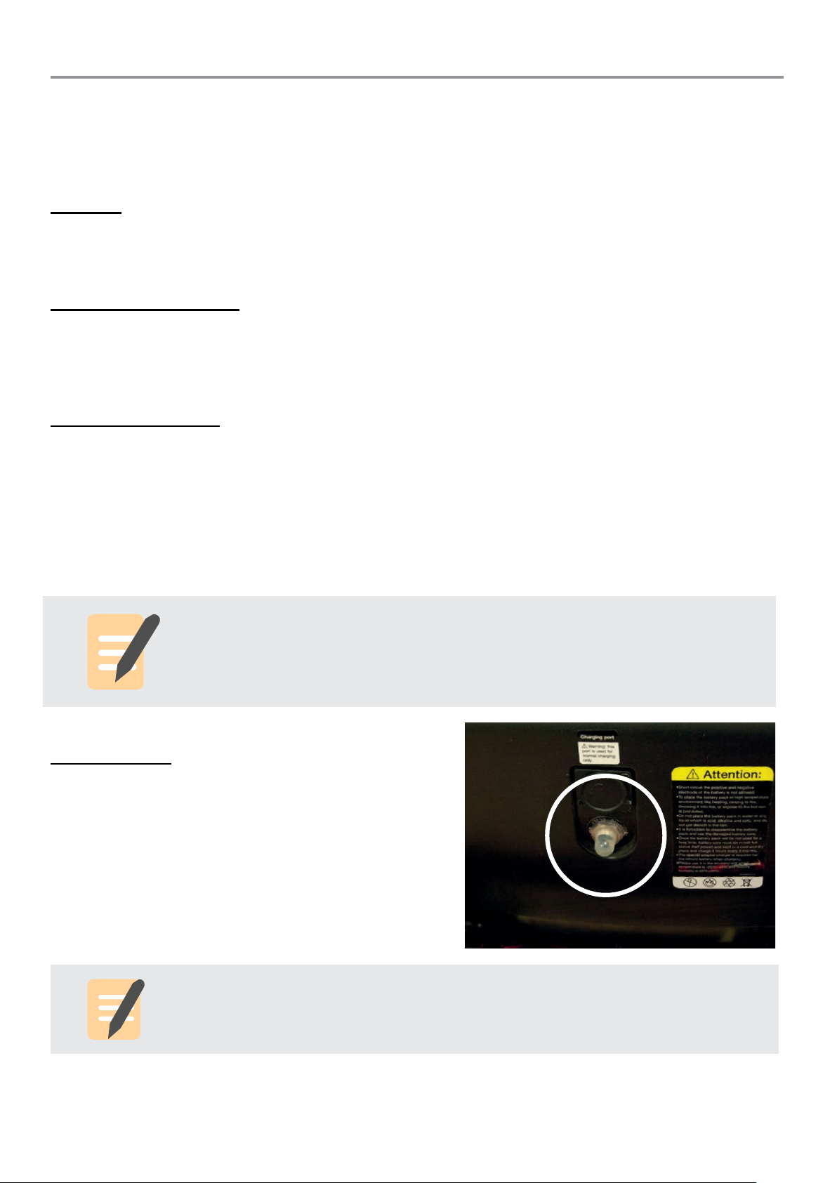
10 Battery pack charging port
11 Circuit breaker reset button
12 Anti-tippers
Page 5
5
Safety Advice
Every care has been taken to ensure that your powerchair will give you a safe, reliable service
provided you adhere to the advice given below and throughout the manual.
Do:
• Read this manual carefully before using your powerchair.
• Turn the power off when transferring to and from the powerchair.
• Select a slow speed when going up or down gradients (max 6°) or over uneven ground.
• Keep your feet on the footrest whilst driving.
• Ensure the seat is locked in the ‘forward’ position.
• Turn the power off when not in use.
• Follow the maintenance guide to ensure safe operation of the powerchair.
• Keep batteries fully charged when storing.
• Be aware of other road users when crossing roads.
• Follow the guidance and rules for pedestrians when travelling on the pavement.
• When travelling on a pavement, give pedestrians priority and show consideration for
other pavement users, particularly those with a hearing or visual impairment who may
not be aware that you are there.
Do not:
• Carry passengers.
• Travel on inclines exceeding 6°.
• Traverse across inclines (especially in P325/RS model with the seat at full height).
• Attempt inclines if the surface is slippery.
• Turn sharply at full speed (P325/RS model has built in safety feature that slows the chair
before turning sharply).
• Stand on footrest.
• Exit or enter the powerchair unless the power is switched off.
• Switch off the power whilst driving – this will cause the powerchair to stop abruptly.
• Use the powerchair where you cannot safely or legally walk.
• Attempt to climb kerbs except drop down kerbs.
• Use the powerchair if under the influence of alcohol or any medication that may affect
your ability to drive the powerchair safely.
• Use a mobile phone whilst driving the powerchair.
• Attempt to negotiate steps or escalators.
• Attempt to tow any other devices.
• Exceed the stated weight limit.
• Connect any unauthorised devices to the battery as this could cause permanent
damage and void your warranty.
• Use any other battery/charger other than those supplied by RMA.
• Travel through water or over rough or soft terrain (mud, sand etc.) or through long grass
and avoid cobbles if possible.
• Travel on the road except when crossing between pavements.
• Lift the powerchair by the seat assembly or any plastic part.
• Suddenly shift your centre of gravity as this could make the powerchair unstable.
• Use the chair as a seat in a motor vehicle (unless your chair is model P325/CS and is
secured properly).
Page 6
6
Adjustments
Caution:
Should any damage occur to the lap belt, please replace immediately.
The user should transfer to a bespoke vehicle seat whilst being transported.
DO NOT sit in the powerchair whilst in any moving vehicle.
Seat Height Adjustment (P325 & P325/CS models)
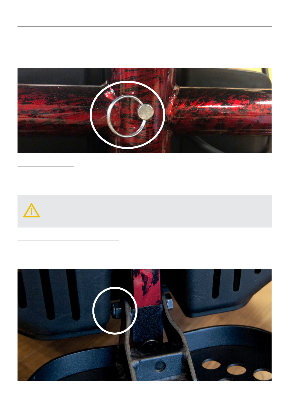
The height of the seat can be adjusted by pulling out the pin located below the seat, moving the seat
up/down to the required height and reinserting the pin into the desired hole of the tube. Do not sit in
the seat when adjusting the seat height and make sure the pin is correctly reinserted before using
the powerchair. See joystick controller instructions for seat height adjustment for P325/RS model.
Lap Belt Adjustment
Ensure that you are sitting back fully into the seat with your pelvis as upright as possible and not
leaning to one side. Close the buckle and position the belt so that the hip bones can be felt above
the lap belt. Adjust the strap length by pulling on the open end of the belt. As a guide, the belt should
be adjusted so that there is sufficient room for two fingers to slide between your body and the belt.
Flip Up Footplate Height Adjustment
The footplate can be easily moved out of the way by flipping upwards towards the seat.
The height of the footplate can be adjusted by fully undoing the two fixing bolts which attach the
footplate. When removed, place the footplate at the desired height and re-insert the bolts and tighten
fully. Both screws must be used when re-fitting.
Page 7
7
Seat Swivel & Removal (P325 & P325/CS models)
Caution:
For all models, the joystick MUST be unplugged before removing the seat to prevent
damage to the cable.
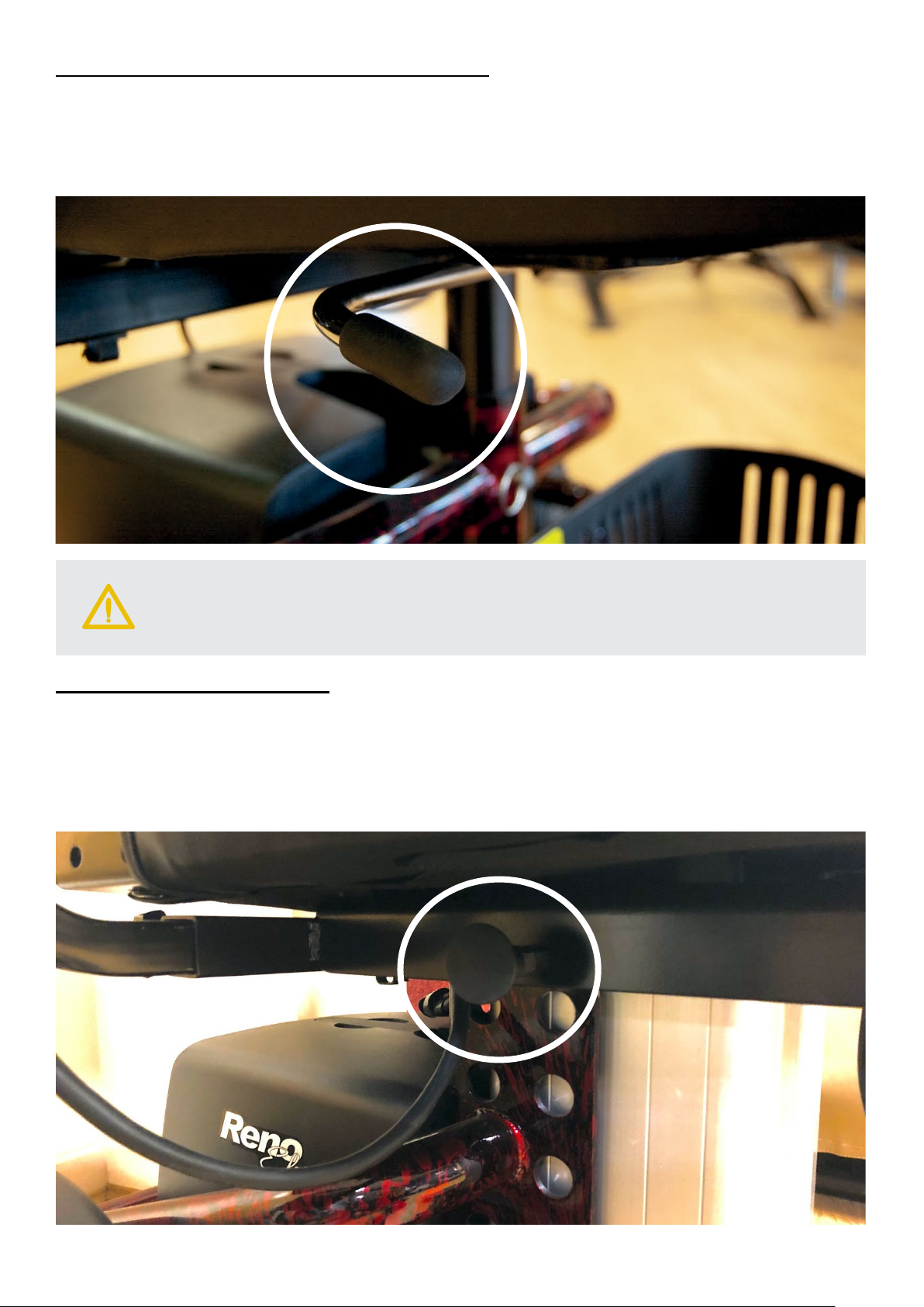
The seat can be swivelled around the base unit. Lift up on the lever on the right side of the seat and
rotate as necessary. To remove the seat, fold down the backrest, lift up the lever and gently pull the
seat upwards away from the chair at the same time. The seat is required to be swivelled to remove
the battery pack. Replace the seat by doing the opposite procedure and make sure the seat is
properly refitted before use.
Seat Removal (P325/RS model)
Ensure the seat is adjusted to the lowest height before removal. The seat can then be removed by
pulling the pins located underneath the seat outwards (one on each side) at the same time and
pulling the seat upwards until it becomes free and lifts off the chair. Replace the seat by doing the
opposite procedure. There are four fixed pins on the bottom of the seat that should relocate into 4
notches on the seat plate. The two release pins should click into place when the seat is secured
properly, always ensure the seat is properly relocated before use.
Page 8
8
Arm Width Adjustment
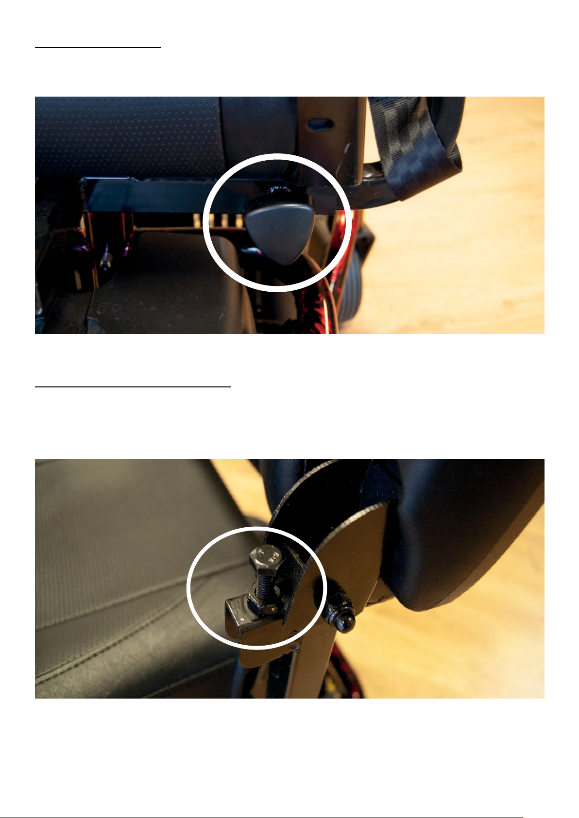
The armrest width can be quickly adjusted without tools. At the rear of the seat there are two hand
knobs. Loosen the hand knob and adjust the armrests by pushing them inwards or pulling them
outwards and re-tighten the hand knobs when at the desired position.
Flip-up Armrests Angle Adjustment
The armrests flip up to allow for easier transfers. Simply lift the armrest upwards when needing to
move the armrest out of the way.
The angle of the armrest can be adjusted by undoing the locking nut and setting the arms at the
desired height by screwing the bolt in or out. The nut should then be tightened to lock the adjustment
in place.
Page 9
9
Joystick Depth Adjustment
Caution:
Never leave the powerchair unattended whilst in freewheel mode as it will roll away
down an incline. ‘Freewheel’ mode should only be used in an emergency to move the
powerchair due to power failure. Never move the powerchair in this mode whilst it is
occupied.
DO NOT use your feet to operate the electromagnetic brakes as this will apply
excessive force and damage the mechanisms. This could lead to the powerchair
being inoperable.
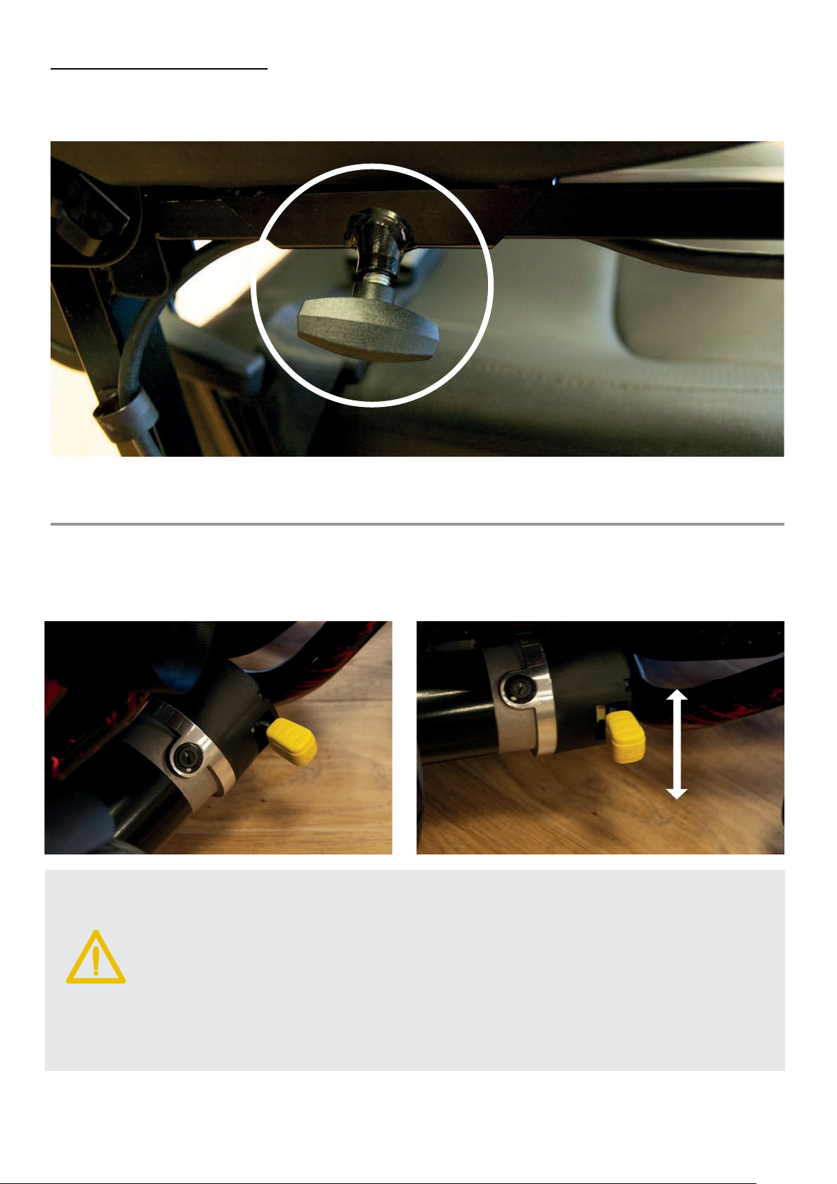
It is possible to adjust the depth of the joystick controller for added comfort. Simply loosen the hand
knob and slide the joystick to the required length and fully re-tighten the hand knob. The joystick can
also be placed on either arm of the powerchair depending on the user’s preference.
Brake Release / Freewheel Operation
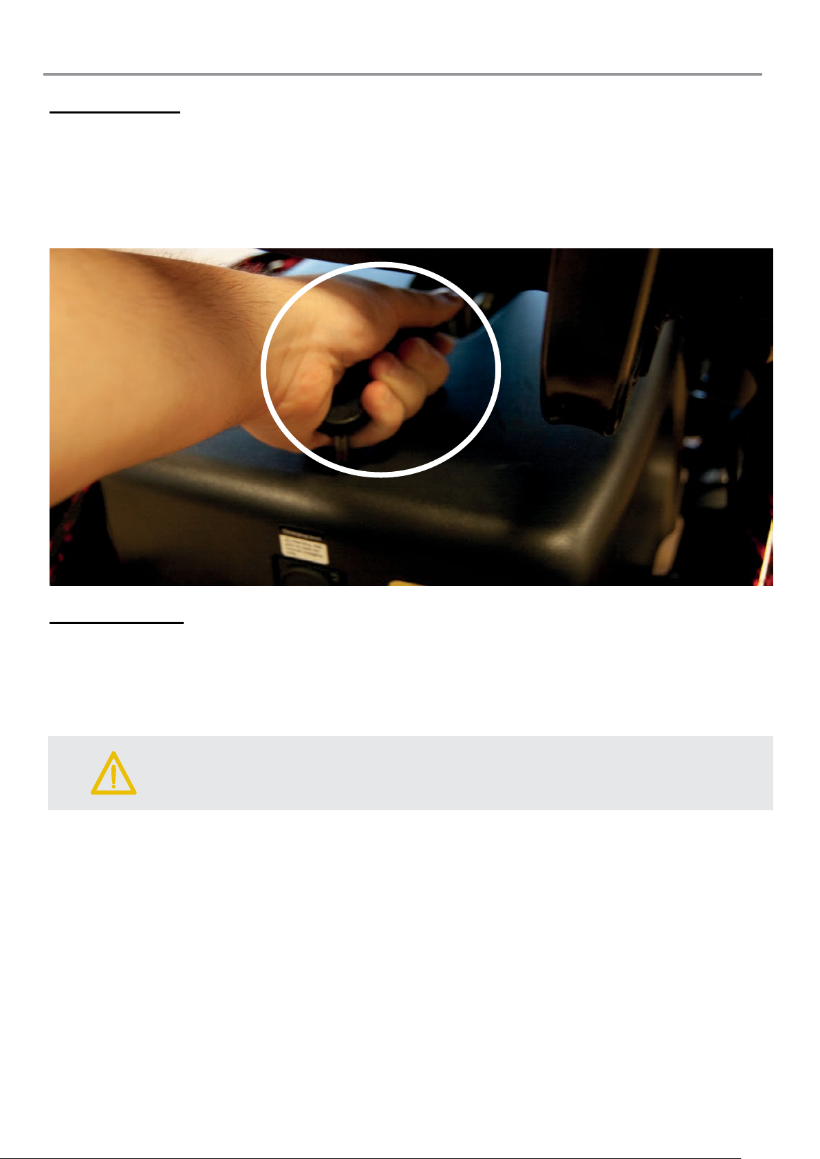
To release the electromagnetic brakes, go to the sides of the powerchair and move the two levers
down, as indicated by the labelling. The powerchair may now be pushed. Move the lever back up to
re-engage the brakes before use.
Page 10
10
Battery
Caution:
The joystick controller should be switched off when charging.
Battery Removal
The battery can be easily removed for external charging, away from the powerchair or for storage.
Unless the seat is adjusted to the highest position, the seat must be swivelled to the left or right by
90 degrees (or removed), the battery can then be removed by holding the handle and lifting the pack
out towards the rear of the chair.
Always ensure the power is switched off at the joystick before removing the battery pack.
Battery Charging
The battery charger is an off board 2-Amp switch mode type.
The battery charging port is located on the underside of the joystick controller and there is also a
charging port on the battery pack. This special feature allows the battery to be charged
independently of the main powerchair.
Before using your powerchair for the first time be sure to fully charge the battery pack, this may take
up to 8 hours.
To charge the battery connect the 3-pin male charger plug into the charging socket on the
joystick/battery pack. Plug the 3-pin mains plug into a wall socket and switch on.
There will be a constant red light on the charger which indicates power is on. When charging, the
light changes to yellow and a green LED light indicates charging is complete.
Page 11
11
Caution
Do not open the battery pack. Always seek the advice of your mobility retailer
should fuses or batteries need replacing. Failure to do so could result in damage
to the battery pack.
If the powerchair is to be unused for extended periods fully charge the battery pack
and remove it completely from the powerchair. The battery pack should not be
stored for prolonged periods in cold environments (do not leave it outside in a
garage/shed over the winter period if not used) as this can cause permanent
damage to the batteries.
Caution
:
Do not charge the battery for longer than 12 hours. Always charge the battery in a
well
if the
powerchair is not to be used for a prolonged period of time (2 to 3 weeks).
Failure to do so could result in permanent damage and render the battery
unusable. Wherever possible do not interrupt the charge cycle until the battery is
fully charged. C
If the charging lead should get damaged discontinue use immediately and seek a
replacement from your
. ONLY USE THE CHARGER SUPPLIED WITH
YOUR POWERCHAIR. Do not leave the charger plugged into to the charger port
after the charge is complete.
Pb
-ventilated indoor area. You must still maintain charging the battery even
ontinual interruption can permanently damage the battery.
supplier
Battery Pack
The Reno has a 21-22Ah AGM (2 x 12v) battery pack which has the advantage of being removable
for charging off board.
:
Battery Disposing & Recycling
Batteries must always be recycled correctly. Do not dispose of them with your domestic
refuge.
For further information regarding your nearest recycling facility please contact your local
authority.
Page 12
12
Operating The Powerchair
Caution:
Do not reverse down an incline without supervision.
Select an area with plenty of space. Ensure that when seated in the powerchair you are in a
comfortable position and can easily and freely operate the controls.
Moving Off & Steering
Turn the power on and check that your battery is fully charged. Set your speed to a low setting.
Gently push the joystick in the direction you wish to travel. The harder you push the joystick the
faster you will travel. Release the joystick, this will automatically return to the centre position and the
electromagnetic brakes will be activated. See below for further joystick details.
Reversing
Before reversing, please ensure that the area behind is free from any hazard or obstruction. Pull the
joystick towards you to move in a reverse direction.
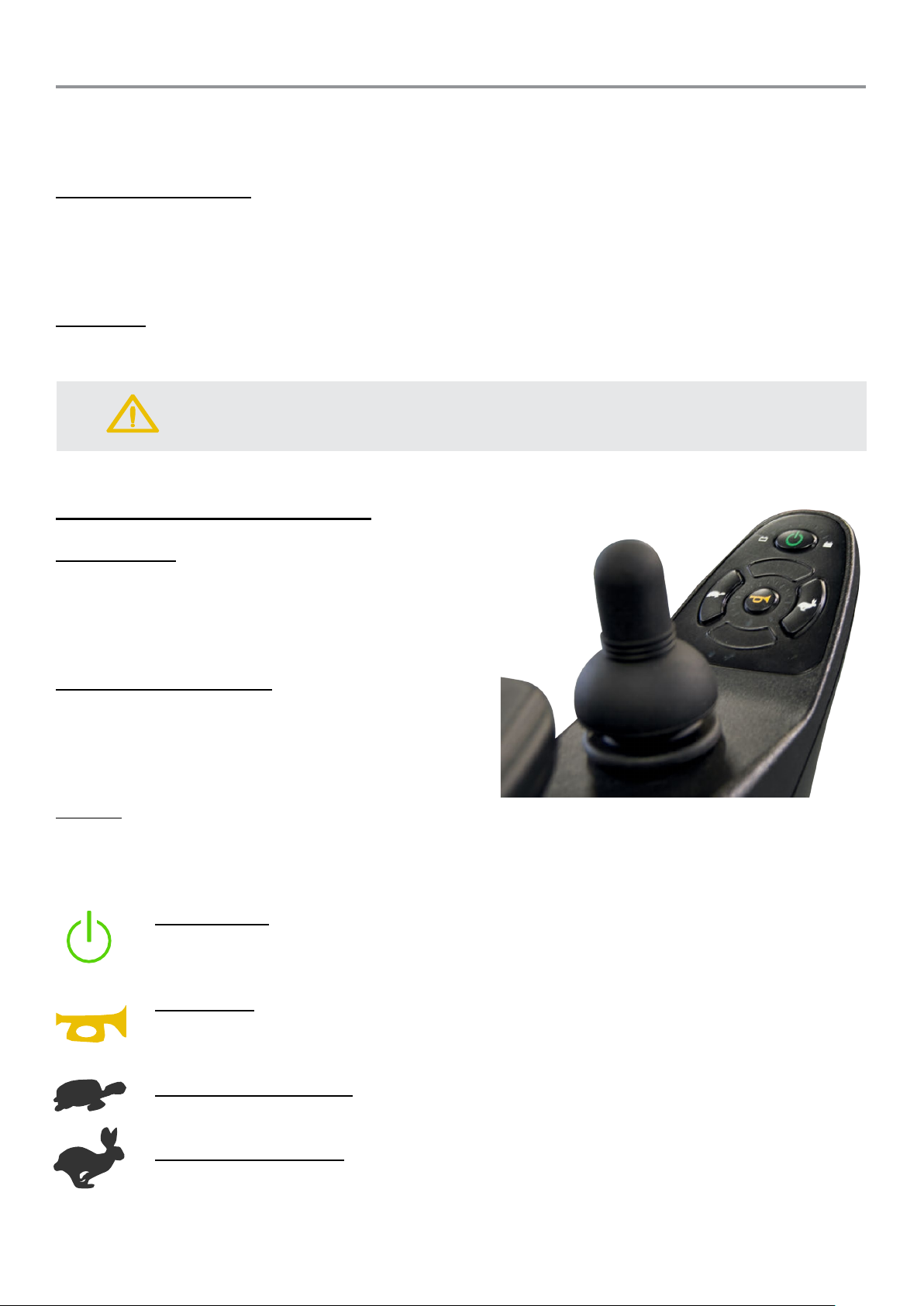
P325 & P325/CS Joystick Controller
Battery Gauge
This is an 8-segment display around the top of the
power switch, which indicates if the joystick is
switched on and gives the state of charge on the
battery.
Maximum Speed Indicator
This is a 5-segment display around the horn button,
which indicates the speed setting selected. 1 bar
indicates the slowest setting, and 5 bars indicates
the fastest setting.
Joystick
This controls the speed and direction of your powerchair. Push the joystick in the direction you want
to go. The further you push it, the faster the speed will be. Releasing the joystick will automatically
engage the brakes and bring the powerchair to a controlled stop.
On/Off Button
This button turns your joystick controller on and off. Do not use this button to stop the
power chair, except in an emergency.
Horn Button
This button operates your powerchair’s horn. This should only be used to warn others
of your presence and not as a rebuke of any form.
Speed Decrease Button
This button decreases your maximum speed.
Speed Increase Button
This button increases your maximum speed.
Page 13
13
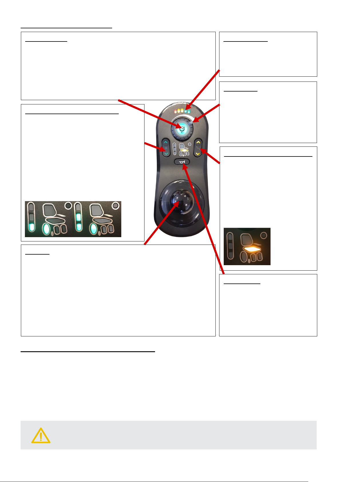
P325/RS Joystick Controller
Battery Gauge
along the top of the power
of charge on the battery.
On/Off Button
then this will flash red.
Horn Button
This button operates your
Seat Height Selector Buttons
When this is selected, the
This allows the joystick to
Wheel/Speed Selector Buttons
below. This allows the
Joystick
towards you (backwards) will higher the seat.
Speed Dial
is dial controls the
maximum speed of the
to the right increases the
Caution:
Should the rubber boot/gaiter or keypad on the joystick become damaged,
replace immediately to prevent damage to the internal components.
This button turns your joystick controller on and off. A green
light indicates the joystick is on and no light signals the joystick
is switched off.
Do not use this button to stop the power chair, except in an
emergency.
If there is an error with the system while it is powered up,
Press either the green backlit up or
down button to select the wheel speed
option. When this is selected, the chair
wheel will turn green, as shown in the
pictures
joystick to then be used to control the
wheel direction and overall speed of
the chair. The up and down buttons
can be used to select one or two bars
of speed, two bars offers an extra 1520% max speed compared to one bar.
This is a 5-segment display
switch, which gives the state
Th
powerchair. Turning the dial
speed and turning the dial to
the left decreases the speed.
Press either the orange
backlit up or down button to
select the seat height option.
chair seat will turn orange, as
shown in the picture below.
then be used to control the
seat height of the chair.
Depending on what control has been selected, this controls
the seat height or chair speed and direction.
When the wheel speed has been selected, the direction in
which you push the joystick will move the chair in the same
direction. The further you push it, the faster the speed will be.
Releasing the joystick will automatically engage the brakes
and bring the powerchair to a controlled stop.
When the seat height has been selected, pushing the joystick
away from you (forward) will lower the seat and pulling it
powerchair’s horn.
This should only be used to
warn others of your presence
and not as a rebuke of any
form.
‘Lock’ Function For All Model Controllers
Your controller is equipped with a lock function to prevent any unauthorised use.
To lock the controller:
Turn the power on and press and hold the power button until the system bleeps (on P325 & P325/CS
models) or flashes red (on P325/RS model). The chair is now disabled/locked.
To unlock the controller:
Press the power button until the indicator lights go from left to right.
Press the horn button two times within 10 seconds and the joystick will unlock.
Page 14
14
Drop Kerb Climbing
Caution:
Do not hit the drop kerb at speed and do not attempt to climb a drop kerb if the
anti
Please take time to get accustomed to your new powerchair before driving in
heavily pedestrianised areas.
Caution
Never reverse down a drop kerb or ramp onto a main thoroughfare.
Edge of drop kerb
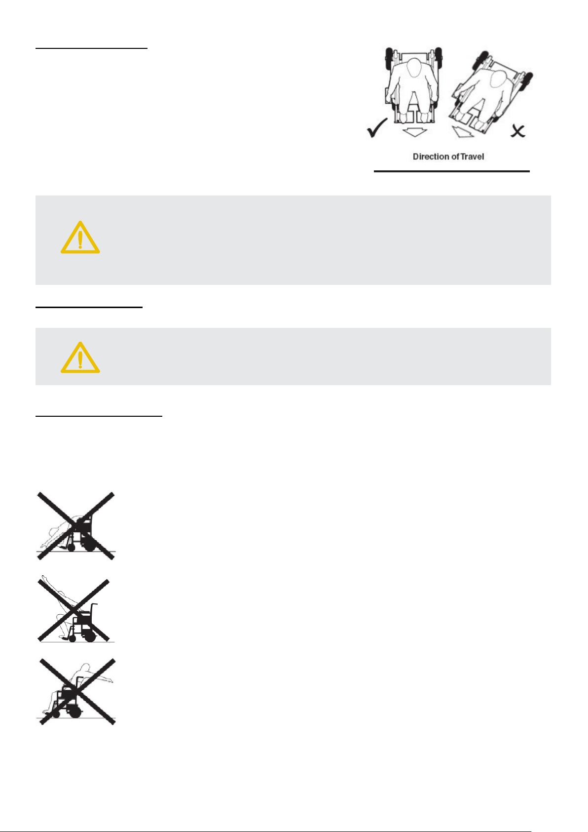
We recommend that a suitable access point such as a drop
kerb or ramp be used at all times.
When driving up the drop kerb, always approach the edge as
shown in the illustration. This ensures maximum stability.
-tipping castors wheels have been removed.
Drop Kerb Descent
Do not reverse down drop kerbs, please use a ramp/drop-kerb in forward motion to descend.
:
Reaching & Stretching
Care must be taken when reaching and stretching for objects as this may affect the stability of the
powerchair.
When attempting to reach for objects it is very important that the power is OFF.
Do not attempt to reach for objects on the floor by leaning forward or reaching
between your knees.
Do not attempt to reach for high objects by moving to the front of the seat. NEVER
stand on the footplate to reach for objects.
Do not attempt to reach for objects behind you by leaning over the back of the seat.
Page 15
15
Disassembly & Assembly
Caution
We advise caution when disassembling and lifting items. You must ensure that
the person undertaking the action is able to safely and correctly handle the weight
to avoid any personal injury.
The motors must be in the Drive / Engaged position to disassemble and assemble
the powerchair.
Disassembly
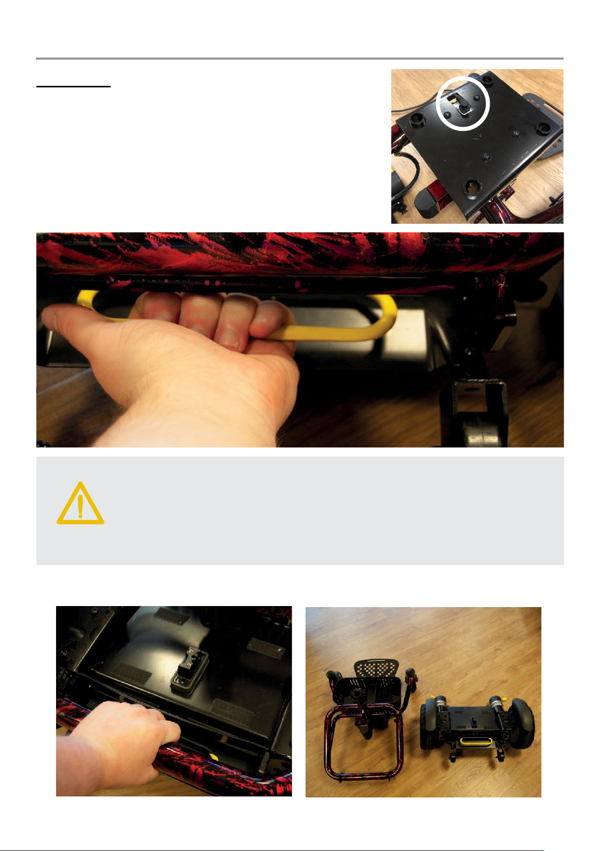
Remove the seat and battery pack as described previously,
ensuring the power is off and the joystick cable is unplugged.
On the P325/RS model, the seat should be adjusted to the lowest
height before dismantling and an extra cable needs to also be
unplugged to detach the seat from the battery, see circle in photo.
When you have done this, locate the yellow release lever as
shown below and pull backwards – this will cause the frame to
separate.
:
The front chassis can then be lifted away from the rear (as shown below left) and the pieces separate
for transportation (as shown below right).
Page 16
16
Assembly
Caution:
Please take care not to trap the
Caution:
Always check that both parts are fully connected before refitting the seat and
battery box.
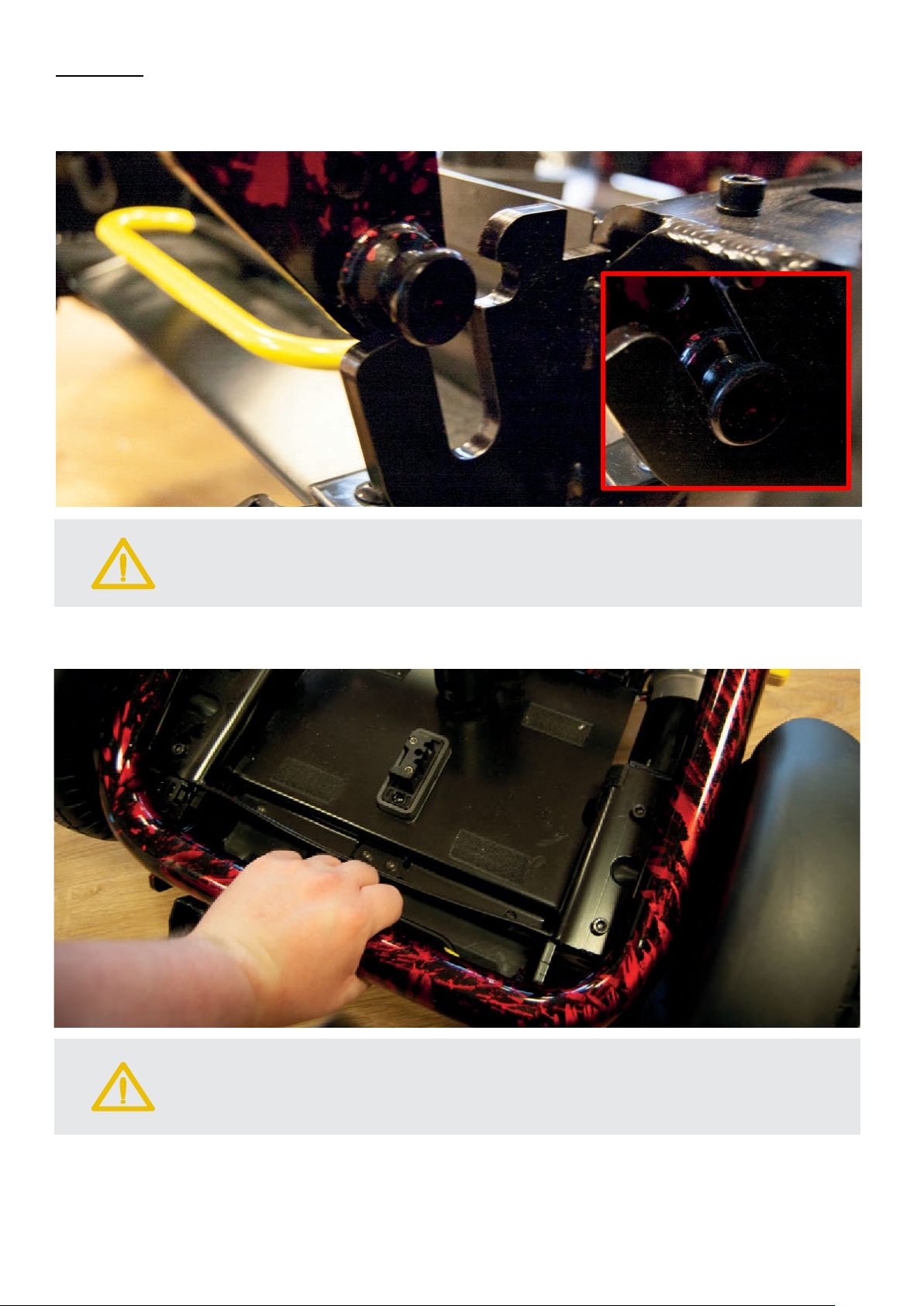
To reassemble, locate the pivot pin of the front chassis into the receiving slots of the rear chassis
(each side) and lower to the bottom location.
The picture located in the bottom right red box shows the pin fully located in the bottom position.
joystick cable between the two parts.
Push down on the rear part of the frame as shown below. This will reconnect the two parts of the
frame together. You will hear the latch ‘click’ into place.
Then, refit the battery box, replace the seat (firstly ensuring the seat height cable is attached on the
P325/RS model) and reconnect the joystick.
The Reno Elite Powerchair is now ready for use.
Page 17
17
Transportation
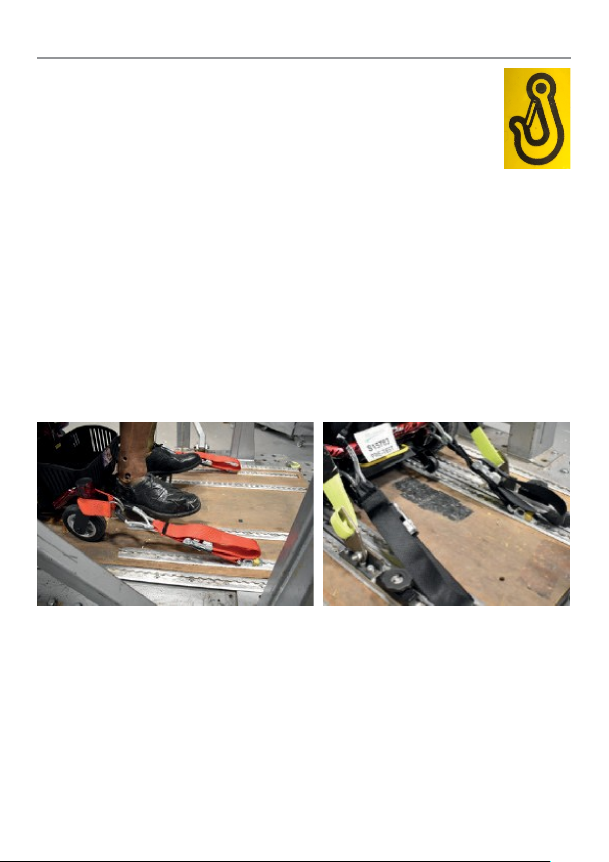
The powerchair should be transported in a cargo area/boot. This can be fully
assembled (if there is enough room in the area without damaging the chair and when
secured properly using the tie down points) or dismantled into its component pieces
(as described previously).
The tiedown points are indicated by the yellow icon shown opposite.
Reno Elite P325 and P325/RS models should not be used as a seat in a motor vehicle. Wheelchair
users should transfer to the vehicle seat and use the vehicle manufacturer installed restraint systems
whenever it is feasible, and the unoccupied wheelchair should be stored in a cargo area or secured
in the vehicle during travel.
Reno Elite P325/CS model has been crash tested and approved to be used as a seat in a motor
vehicle when conforming to the specifications detailed below. However, transferring to a vehicle seat
is still recommended wherever possible.
The Reno Elite Powerchair P325/CS model (fitted with a captain seat) was tested to
ISO7176/19:2008 on 04/12/2018 by Millbrook Services. Test No. S15783.
The powerchair is designed to be forward-facing when used as a seat in a motor vehicle, when used
with restraints which conform to ISO 10542:2 and when attached to the specified tie down points on
the powerchair.
Unwin Safety Systems items:- Front – Unwins OF02 Rear – Unwins OR02
Page 18
18
Maintenance
Note:
Should the circuit breaker continue to trip, turn off the powerchair immediately
and consult your
Note:
Should any part of your powerchair need replacing or repairing please contact
your local RMA
Failure to do thi
The powerchair has been designed to provide the user with a long, reliable life provided it is correctly
maintained and regularly serviced by an authorised supplier. However, due to inevitable wear and
tear and technological improvements, it is recommended by the MHRA (Medicines and Healthcare
products Regulatory Agency) that the average useable life of this powerchair is five years.
Cleaning
The frame and seat of the powerchair should be cleaned using a damp cloth and gentle detergent.
Do not use abrasive cleaners or solvents, as this will damage the plastic components. Do not spray
water (hose or pressure washer) onto the powerchair as this may cause damage to the electronics.
Storage & General Care
We recommend that the powerchair is always stored in a dry environment such as in the home or
garage to protect the chassis and other components from corrosion. Do not leave the powerchair
outside during rainstorms. If the powerchair is wet, wipe with a dry cloth to ensure there is no ingress
of water into the internal components of the powerchair.
Routine Maintenance
We suggest that your powerchair should undergo a full service at least once a year by an authorised
RMA supplier.
Please check the following on a weekly basis:
• The tyres are in good condition.
• The wheels spin freely (castors).
• Moving parts, pivots and frame fixings are not damaged or worn.
• All hand knobs and levers are secure.
supplier to undertake any maintenance.
s may void your warranty.
Circuit Breaker
Your powerchair is fitted with the latest in electronic
controls that are programmed to protect the electrical
system from abnormal overloads. Fitted for extra
protection is a circuit breaker, which is located under
the carry handle of the battery pack, by the charging
point. Should there be a situation where your
powerchair stops for no apparent reason please check
that the circuit breaker has not tripped. Simply press
the button to reset the circuit breaker.
supplier.
Page 19
19
Problem Checklist
Flash
check connection /
check connection
Note:
If your powerchair fails to operate after checking the above possible faults consult
your local supplier immediately.
Also ensure that the joystick has not been accidentally locked
If your powerchair fails to operate, please check the following:
• The unit is switched on.
• All plugs and connections are firmly fixed.
• Battery level shows full charge.
• Freewheeling device is in the drive position.
• Circuit breaker has not tripped.
• Battery and controller lead are properly connected.
• If the free wheel device has been operated with the powerchair switched on, the powerchair
will not operate until the unit has been turned off and on again.
Joystick Error Codes
Your controller has the ability to diagnose possible errors in the electrical system, which may prevent
your powerchair from operating. In P325 and P325/CS models, these are displayed by a flashing
‘spanner’ symbol on the controller. In the P325/RS model, the power button on the controller will
flash red. The number of flashes (flash code) will indicate the possible fault, the tables below show
what each flash code corresponds to.
For P325 & P325/CS Models:
Flash
Code
1 User error - switch unit off and on.
2 Battery fault - check fully charged.
3
4
5
6
7 Joystick fault - check connection / cable.
8
9
Right hand motor fault - check
Left hand motor fault - check connection
Right side brake fault - check freewheel
Left side brake fault - check freewheel
Controller fault - check connection /
Communication fault - check
Possible Fault
connection / motor brushes.
/ motor brushes.
lever position.
lever position.
cable.
connections.
Code
1
2
3
4
5
6
7
For P325/RS Models:
Possible Fault
Controller / joystick fault - check
connection / cable.
Network or configuration error - check
cables, connections, battery charge and
charger.
Left hand motor fault -
motor brushes.
Right hand motor fault -
/ motor brushes.
Left side brake fault - check freewheel
lever position.
Right side brake fault - check freewheel
lever position.
Module error (other than controller) -
check cables, connectors and the battery
is recharged.
10 Unknown fault.
– refer to page 13.
Page 20

20
Further information
General Use
Take heed of the information given in this manual regarding safety and the maintenance of your
powerchair. If adhered to, your powerchair should give you years of reliable mobility.
Driving In Pedestrian Areas
When using the powerchair in pedestrian areas always lower your maximum speed to that of the
pedestrians around you. Remember the stopping distance of your powerchair and always allow
enough space to stop safely to avoid collisions with pedestrians or other objects.
Weather & Outdoor Conditions
During periods of sunny weather, it is possible that surfaces of your powerchair may reach high
temperatures (as with motor vehicles). Please take precautions if leaving the powerchair in direct
sunlight for any period of time. Seek shade or cover the seat and joystick to keep any temperature
increases to a minimum.
During everyday use, do not use in rain showers or travel through puddles. Avoid use in areas where
the powerchair could become contaminated with sand or abrasive materials.
Health Factors
Suitability for this product has been assessed on the user’s current state of health. It is essential
that the user regularly monitors their ability to use the powerchair safely.
Product Stability
Powerchairs are designed to allow the user flexibility of movement in restricted areas. Driving at
maximum speed and attempting sharp turns can create a situation where the product becomes
unstable. Therefore, it is essential that the user pays attention the guidance set out in this manual.
The main factors affecting stability are:
• Maximum speed setting
• Seat height
• User movement
• User’s manoeuvres
• Gradients or slopes
Safety Information Regarding Electromagnetic Interference (EMI)
Powerchairs and powerchairs are designed to operate under certain conditions.
However, radio waves or electromagnetic fields may affect the operation of the powerchair. The
source of EMI could be radio or television transmitters or portable devices such as mobile phones,
portable CB radios etc. Should any unintentional movement occur turn the powerchair off as soon
as safely possible.
Page 21

21
Warnings
Read this manual fully before operating the powerchair.
Persons with lower body amputations should not use this device unless evaluated with
artificial limbs fitted, as stability may be compromised due to an irregular centre of gravity.
Do not use the powerchair if under the influence of alcohol or any medication that may affect
your ability to drive the powerchair safely. Do not use a mobile phone whilst driving the
powerchair.
Always exit and enter the powerchair when the power is switched off. Do not switch off the
power whilst driving as this will cause the powerchair to stop abruptly.
Do not turn sharply when travelling at full speed or shift your centre of gravity suddenly as
these things can cause the chair to become unstable.
Do not exceed the weight limit of the powerchair, carry passengers or tow any other devices.
Do not stand on the footrest as this may unbalance the chair.
Care must be taken when reaching and stretching for objects as this may affect the stability
of the powerchair.
Be extremely careful around inclines; do not travel on inclines exceeding 6°, traverse across
inclines, attempt inclines if the surface is slippery and do not reverse down an incline without
supervision. This is especially relevant when the seat is at full height on the P325/RS model.
Please take time to get accustomed to your new powerchair before driving in heavily
pedestrianised areas.
Only use the powerchair where you can safely and legally walk. Do not travel on the road
except when crossing between pavements. Be aware of road users when crossing.
When travelling on a pavement, you must follow the guidance and rules for pedestrians. Give
pedestrians priority and show consideration for other pavement users, particularly those with
a hearing or visual impairment who may not be aware that you are there.
Do not attempt to climb kerbs unless they are drop kerbs and when using these; never reverse
down a drop kerb or ramp onto a main thoroughfare, do not hit the drop kerb at speed and
do not attempt to climb a drop kerb if the anti-tipping castors wheels have been removed.
Do not attempt to negotiate steps or escalators or travel through water or over soft terrain.
Do not lift the powerchair by the seat assembly or any plastic part as this may damage the
chair.
Should any severe damage occur to any of the part of the powerchair, contact your RMA
supplier immediately for repairs or replacement parts. This is especially relevant for electrical
components/wires, the joystick/controller and lap belt.
The user should transfer to a bespoke vehicle seat whilst being transported whenever
possible.
Page 22

22
When making adjustments to any part of the chair, always make sure that bolt/pins are
properly tightened or relocated before sitting in and using the chair.
We advise caution when disassembling and lifting items. You must ensure that the person
undertaking the action is able to safely and correctly handle the weight to avoid any personal
injury.
The joystick must be unplugged before removing the seat to prevent damage to the cable.
When reassembling the chair, take care not to trap the joystick cable between the different
parts of the chair.
The motors must be in the Drive/Engaged position to disassemble and assemble the
powerchair.
When reassembling the chair, always check that the component parts are fully connected
and refitted before sitting in and using the chair.
The joystick controller should be switched off when charging.
Do not charge the battery for longer than 12 hours. Wherever possible do not interrupt the
charge cycle until the battery is fully charged. Continual interruption can permanently damage
the battery Always charge the battery in a well-ventilated indoor area.
You must still maintain charging the battery even if the powerchair is not to be used for a
prolonged period of time (2 to 3 weeks). Failure to do so could result in permanent damage
and render the battery unusable.
If the powerchair is to be unused for extended periods fully charge the battery pack and
remove it completely from the powerchair. The battery pack should not be stored for
prolonged periods in cold environments (do not leave it outside in a garage/shed over the
winter period if not used) as this can cause permanent damage to the batteries.
If the charging lead should get damaged, discontinue use immediately and seek a
replacement from your supplier.
Only use the charger supplied with your powerchair and do not connect any unauthorised
devices to the battery as this could cause permanent damage and void your warranty.
Do not leave the charger plugged into to the charger port after the charge is complete.
Do not open the battery pack. Always seek the advice of your mobility retailer should fuses
or batteries need replacing. Failure to do so could result in damage to the battery pack.
Never leave the powerchair unattended whilst in freewheel mode as it will roll away down an
incline. ‘Freewheel’ mode should only be used in an emergency to move the powerchair due
to power failure. Never move the powerchair in this mode whilst it is occupied.
Do not use your feet to operate the electromagnetic brakes as this will apply excessive force
and damage the mechanisms. This could lead to the powerchair being inoperable.
Page 23

23
Warranty Terms & Conditions
This is to certify that your RMA product is warranted for a period of 12 months from the date of
original purchase. This warranty is not transferable.
Should a defect or operating fault arise within this period the supplier from where the product was
originally purchased should be notified immediately. Failure to register the fault may invalidate the
warranty. The supplier from where the product was purchased is responsible for any warranty
repairs.
RMA warrants that if a fault occurs within this period due to faulty workmanship or materials that the
product will be repaired (or replaced at the Company’s discretion) free of charge.
Any unauthorised modifications will invalidate the warranty.
Parts which are subjected to normal wear and tear, accidental damage, neglect or misuse are
excluded from this warranty. Normal wear and tear parts include tyres, chassis covers, bulbs, seat
coverings etc.
Component parts replaced outside this period carry a six-month warranty. (Standard terms and
conditions apply for this period).
Model:
Serial No:
Purchase Date:
Supplier Stamp
Page 24

24
Notes
Invamed
York Road
Bridgend Industrial Estate
Bridgend
South Wales
United Kingdom
CF31 3TB
Telephone: 01656 674488
Fax: 01656 674499
Email: sales@invamed.co.uk
Web: www.invamed.co.uk
 Loading...