

Page 1

Owner's Operator And Maintenance Manual
®
Excelerator
Li'l Excelerator
Excelerator XLT
Excelerator XLT 2000
DEALER: THIS MANUAL MUST BE GIVEN TO THE USER OF
THE WHEELCHAIR.
USER: BEFORE USING THIS WHEELCHAIR, READ THIS
MANUAL AND SAVE FOR FUTURE REFERENCE.
Page 2

SPECIAL NOTES
SPECIAL NOTES
W
A
R
N
I
N
G
WARNING
DO NOT OPERATE THIS EQUIPMENT WITHOUT FIRST READING
AND UNDERSTANDING THIS MANUAL. IF YOU ARE UNABLE TO
UNDERSTAND THE WARNINGS, CAUTIONS AND
INSTRUCTIONS, CONTACT YOUR INVACARE DEALER OR
INVACARE CUSTOMER SUPPORT AT (800) 532-8677 BEFORE
ATTEMPTING TO USE THIS EQUIPMENT - OTHERWISE INJURY
AND/OR EQUIPMENT DAMAGE MAY RESULT.
WARNING/CAUTION notices as used in this manual apply to hazards or unsafe practices which
could result in personal injury or property damage.
NOTICE
THE INFORMATION CONTAINED IN THIS DOCUMENT IS SUBJECT TO CHANGE WITHOUT NOTICE.
S
P
E
C
A
L
N
O
T
E
S
WARNING
EXCELERATOR USER
As a manufacturer of the Excelerator, Invacare endeavors to supply an Excelerator to meet many
needs of the end user. However, final selection of an Excelerator to be used by an individual rests solely
I
with the user and his/her health care professional capable of making such a selection.
EXCELERATOR TIE-DOWN RESTRAINTS AND SEAT POSITIONING STRAPS
Invacare recommends that the Excelerator users NOT be transported in vehicles of any kind while in an
Excelerator. As of this date, the Department of Transportation has not approved any tie-down systems
for transportation of a user while in an Excelerator, in a moving vehicle of any type.
AS REGARDS RESTRAINTS - SEA T POSITIONING STRAPS - IT IS THE OBLIGATION OF THE DME DEALER, THERAPISTS AND OTHER HEALTH CARE PROFESSIONALS TO DETERMINE IF A SEATING POSITIONING STRAP IS
REQUIRED TO ENSURE THE SAFE OPERATION OF THIS EQUIPMENT BY THE USER. SERIOUS INJURY CAN
OCCUR IN THE EVENT OF A FALL FROM AN EXCELERATOR.
SAVE THESE INSTRUCTIONS
2
Page 3

TABLE OF CONTENTS
TABLE OF CONTENTS
NOTE: When using the term EXCELERATOR, it will pertain to the EXCELERATOR, LI'L EXCELERATOR
EXCELERATOR XLT and EXCELERATOR XLT 2000 except when the instructions specifically note otherwise.
SPECIAL NOTES ........................................................ 2
SPECIFICA TIONS ....................................................... 4
PROCEDURE 1 - GENERAL GUIDELINES ............ 5
OPERATING INFORMATION .......................................... 5
SAFETY/HANDLING OF EXCELERATOR ....................... 6
PROCEDURE 2 - SAFETY INSPECTION/
TROUBLESHOOTING/MAINTENANCE ...............8
SAFETY INSPECTION CHECKLIST ................................ 8
TROUBLESHOOTING .................................................... 9
MAINTENANCE ............................................................. 9
PROCEDURE 3 - ASSEMBL Y PROCEDURES ..... 10
EXCELERATOR/LI'L EXCELERATOR ASSEMBLY
PROCEDURES ......................................................... 10
EXCELERATOR XLT/XLT 2000 ASSEMBLY
PROCEDURES ......................................................... 11
PROCEDURE 4 - REAR WHEELS .......................12
INSTALLING/ADJUSTING THE REAR WHEELS
AND QUICK-RELEASE AXLES - EXCELERATOR
AND LI'L EXCELERATOR .......................................... 12
INSTALLING THE REAR WHEELS WITH THREADED
AXLE OPTION - EXCELERATOR XLT/XLT 2000 ......... 12
TIRE/TUBE REPLACEMENT AND TUNING/
REPLACEMENT OF SPOKES .................................. 12
TIRE PRESSURE ........................................................ 12
DETERMINING/ADJUSTING TOE IN/TOE OUT ............. 12
REPLACING CAMBER INSERTS ................................. 13
PROCEDURE 5 - FORK/ SPRING/CRANK ...........14
EXCELERATOR/LI'L EXCELERATOR
FORK ASSEMBLY INSTALLATION ............................. 14
EXCELERATOR/LI'L EXCELERATOR TENSION
SPRING INSTALLATION ............................................ 14
EXCELERATOR/LI'L EXCELERATOR HAND
CRANK ASSEMBLY INSTALLATION .......................... 14
EXCELERATOR XLT/XLT 2000 FORK/CRANK
ASSEMBLY REPLACEMENT .................................... 15
EXCELERATOR XLT/XLT 2000 TENSION SPRING OR
ROAD CROWN COMPENSATOR REPLACEMENT/
ADJUSTMENT .......................................................... 16
PROCEDURE 6 - SPEED SHIFTERS .................. 18
LI'L EXCELERATOR - THREE (3) SPEED
SHIFTER CABLE INSTALLATION ............................... 18
LI'L EXCELERATOR - THREE (3) SPEED
SHIFTER CABLE ADJUSTMENT ............................... 18
EXCELERATOR/EXCELERATOR XLT - SEVEN
(7) SPEED SHIFTER INSTALLATION .......................... 19
EXCELERATOR/EXCELERATOR XLT - SEVEN (7)
SPEED SHIFTER ADJUSTMENT/REPLACEMENT -
BEFORE 1997 ONLY................................................. 19
PROCEDURE 7 - CHAIN.....................................20
EXCELERATOR/LI'L EXCELERATOR CHAIN
INSTALLATION w/ SEVEN (7) SPEED HUB .............. 20
EXCELERATOR/LI'L EXCELERATOR CHAIN
ADJUSTMENT ......................................................... 20
EXCELERATOR CHAIN STAY ADJUSTMENT ............. 20
EXCELERATOR XLT/XLT 2000 CHAIN
ADJUSTMENT ......................................................... 20
EXCELERATOR XLT/XLT 2000 CHAIN INSTALLATION
WITH TWENTY-FOUR (24) OR TWENTY-SEVEN
(27)SPEED CASSETTE ............................................ 21
PROCEDURE 8 - P ARKING BRAKE ...................22
USING PARKING BRAKE ........................................... 22
PARKING BRAKE ADJUSTMENT/REPLACEMENT ....... 22
PROCEDURE 9 - BACK/SEA T............................23
BACK HEIGHT ADJUSTMENT (ADJUSTABLE
BACKS ONLY) ......................................................... 23
SLIDING SEAT ADJUSTMENT .................................... 23
EXCELERATOR XLT/XLT 2000 BACK ANGLE
ADJUSTMENT ........................................................24
PROCEDURE 10 - UPHOLSTERY ...................... 25
SEAT UPHOLSTERY REPLACEMENT ....................... 25
BACK UPHOLSTERY REPLACEMENT ....................... 25
PROCEDURE 11 - FOOTREST .......................... 26
EXCELERATOR/LI'L EXCELERATOR FOOTREST
ADJUSTMENT/REPLACEMENT .............................. 26
EXCELERATOR XLT/XLT 2000 FOOTREST AND LEG
GUARD REPLACEMENT ......................................... 27
EXCELERATOR XLT/XLT 2000 USING/REPLACING
FOOTREST STRAP ................................................. 28
PROCEDURE 12 - OPERA TION ......................... 29
HAND CRANK ASSEMBLY ......................................... 29
SHIFTING GEARS ...................................................... 29
BACKING UP .............................................................. 30
BRAKING ................................................................... 30
PARKING BRAKE ....................................................... 30
STEERING/CORNERING ............................................ 31
MOUNTAIN DRIVE OPTION - SEVEN (7) SPEED
SHIFTER ONLY ........................................................ 31
PROCEDURE 13 - OPTIONS .............................. 33
WATER BOTTLE INSTALLATION ................................ 33
TOW BAR INSTALLATION .......................................... 33
REAR SAFETY LIGHT ................................................ 33
COMPUTER INSTALLATION ....................................... 33
SEAT POSITIONING STRAP INSTALLATION............... 33
HORIZONTAL HANDLES ............................................ 33
TRI-PIN QUAD HANDLES ........................................... 33
GLOVES .................................................................... 33
SAFETY FLAG INSTALLATION ................................... 33
SAFETY HELMET ....................................................... 34
LATERAL SUPPORT .................................................. 34
LIMITED WARRANTY.........................................35
T
A
B
L
E
O
F
C
O
N
T
E
N
T
S
3
Page 4

SPECIFICATIONS
SPECIFICATIONS
EXCELERA TOR
14 to 20-inches
15
Fixed 20/18-inches
Rigid
C
S
P
E
F
I
I
Seat Width:
Seat Depth:
Seat-to-Floor
(approx.):
Back Style:
C
A
T
O
N
S
Back Height
(Fixed or Adjustable):
Footrest:
I
Side - Wheel
Clearance:
Rear Axle:
Rear Wheel Camber:
Wheels:
Brakes:
Handles:
Hub:
Spokes:
Shift Levers:
Gears:
Seat Cushion:
Back Upholstery:
Weight:
Shipping Weight:
Options:
* Knobby Tires will reduce side wheel clearance to approximately 1-inch.
Shimano
®
, Nexus®, and Ultegra®- Registered trademarks of Shimano American Corp.
12-16 or 14-18-inches
Adjustable Height/Angle
2-inches - * 2.5-inches
Quick-Release
o
9
- Standard
24-inch Spoke
(Cruiser Tires)
Hand Crank (Internal)
Parking Brake
Ergonomic, Vertical
FRONT - Shimano
Nexus® 7 Speed Hub
REAR - Precision
Black Anodized w/1/2inch Quick Release
Stainless Axles
14 Gauge Stainless
Shimano
7 Speed
Foam Insert
Nylon-Adjustable Tension
50 lbs.
80 lbs.
Computer, Tow Bar,
Horizontal Handles,
Safety Light, Helmet and
Flag, Custom Color, Seat
Positioning Strap, Quad
Cuffs & Gloves, 24-inch
Knobby Tires, Mountain
Drive, Bike Rack,
Water Bottle and Cage,
Tripin Quad Handles.
LI'L EXCELERATOR
12 or 14-inches
12 or 14-inches
Fixed 17.5/15.5
inches
Rigid
12 to 16-inches
Adjustable Height/Angle
2-inches - * 2.5-inches
Quick-Release
9o - Standard
Front - 20-inch Spoke
Rear - Mag (Knobby
Tires)
Hand Crank (Internal)
Parking Brake
Ergonomic, Vertical
®
FRONT - Shimano 3
Speed Hub
REAR - Precision
Black Anodized w/1/2inch Quick Release
Stainless Axles
14 Gauge Stainless
Shimano
3 Speed
Foam Insert
Nylon-Adjustable Tension
40 lbs.
70 lbs.
7 Speed Hub, Helmet,
Horizontal Handles,
Quad Cuffs & Gloves,
Computer, Custom
Color, Seat positioning
Strap, Safety Flag and
Light, Water Bottle and
Cage.
4
EXCELERATOR XLT
14 to 20-inches
15-inches
Fixed 12.5-inches
Adjustable Back
Angle 90O - 110
13-inches (Fixed)
20-inches (Narrow, Tall)
Adjustable Fore and Aft
2-inches - * 2.5-inches
Quick-Release
15o - Standard
24-inch Spoke
(High Performance,
Cruiser or *Knobby)
Hand Crank - (Internal)
Parking Brake
Ergonomic, Vertical
FRONT - Shimano
Nexus 7 Speed Hub
REAR - Precision
Black Anodized w/1/2inch Quick Release
Stainless Axles
14 Gauge Stainless
Shimano
7 Speed
Foam Insert - Optional
Nylon-Adjustable Tension
35 lbs.
80 lbs.
NOTE: Same options
as Excelerator including the following:
24 Speed External
Gearing, Threaded
Axles, Leg Guard
Attachments, Lateral
Supports.
O
EXCELERAT OR
XLT 2000
14 to 20-inches
15-inches
Fixed 12.5-inches
Adjustable Back
Angle 90O - 110
13-inches (Wide)
20-inches (Narrow, Tall)
Adjustable Fore and Aft
2-inches - * 2.5-inches
Quick-Release or
Threaded
o
15
- Standard
24-inch Spoke
(High Performance,
Cruiser or *Knobby)
Dual Hand Caliper
Brakes
Ergonomic, Vertical
FRONT - Shimano 27
Speed External
Cassette XT/Ultegra
REAR - Precision Black
Anodized w/1/2-inch
Quick Release Stainless
or Threaded Axles
14 Gauge Stainless
Shimano - STI
indexed/brake levers
27 Speed
Foam Insert - Optional
Nylon
30 lbs.
80 lbs.
NOTE: Same options
as Excelerator including the following:
Composite Wheels,
Leg Guard Attachments, Lateral Supports, Welded Seat
O
®
Page 5

GENERAL GUIDELINES
This Procedure Includes the Following:
PROCEDURE 1
Operating Information
Safety/Handling of Excelerator
OPERATING INFORMATION
WARNING
Wear your helmet at ALL times when riding the Excelerator.
The bicycle must be adjusted to fit the rider. Check the seat position, back height, quick release threaded
axles, footrest height, hand crank adjustment for smooth operation of your Excelerator.
Before riding your Excelerator, check your brakes. Be sure that the brakes and all other features of your
Excelerator are operating properly.
The user is responsible for normal upkeep and maintaining the Excelerator in proper operating condi-
tion.
The manufacturer is not responsible for failure, damage or injury caused by improper operation or
maintenance by the end-user.
To determine and establish your particular safety limits, practice transferring activities in the presence of
a qualified health care professional BEFORE attempting active use of the Excelerator.
Before attempting to transfer IN or OUT of the Excelerator, every precaution should be taken to reduce
the gap distance. Position the Excelerator on level ground and as close as possible to the object you
are transferring INTO or OUT of. The parking brake of the Excelerator MUST be engaged and the object
you are transferring INTO or OUT of MUST also be secured before attempting any transfers.
Care MUST BE taken when operating on roads, streets or highways.
Operation of the Excelerator is subject to all traffic rules and regulations. (This may include the use of a
safety light and reflectors for dusk/night riding.)
Give pedestrians the right of way.
Slow down at all street interprocedures and observe to the left, to the right and back to left again before
proceeding.
Use proper hand signals when turning.
DO NOT attempt to move up or down an incline with an ice or oil film.
DO NOT attempt to ride over curbs or obstacles. Doing so may cause your Excelerator to turn over and
cause bodily harm or damage to the Excelerator.
DO NOT use parts, accessories, or adapters other than those authorized by Invacare.
G
E
N
E
R
A
L
G
U
I
D
E
L
I
N
E
S
DO NOT attempt to lift the Excelerator by any removable (detachable) parts. Lifting by means of
any removable (detachable) parts of an Excelerator may result in injury to the user or damage to
the Excelerator.
DO NOT stand on the seat or frame of the Excelerator.
If a seat positioning strap is deemed necessary by your health care professional (doctor - therapist),
ALWAYS wear a seat positioning strap.
Avoid all surface hazards.
DO NOT carry any riders.
DO NOT carry any items that may obstruct your view or prohibit you from operating the Excelerator
properly.
DO NOT clean gear hubs with pressure water (e.g. strong water jet, high-pressure cleaner etc.). Water
that penetrates into the hub could lead to function problems. The hub has been adequately lubricated.
However, if the response of the hand crank brake should become too sharp, the brake cylinder MUST
be greased by a brake professional, using special SACHS grease Type A (F & S Part No. 0369135100).
5
Page 6

G
E
N
E
R
A
L
G
U
I
D
E
L
I
N
E
S
TIRE PRESSURE
DO NOT use your Excelerator unless it has the proper tire pressure (p.s.i.). DO NOT overinflate the tires.
Failure to follow these suggestions may cause the tire to explode and cause bodily harm.
DO NOT ride on a flat or underinflated tires. Riding on flat or underinflated tires can cause injury, as well
as, damage to the tire, tube and bicycle.
WEIGHT LIMITATION
The Invacare Excelerator and Excelerator XLT/XLT 2000 have a maximum weight limitation of 250 lbs.
The Invacare Li'l Excelerator has a maximum weight limitation of 150 lbs.
SAFETY/HANDLING OF
EXCELERATOR
“Safety and Handling” of the Excelerator requires the
close attention of the user as well as the assistant. This
manual points out the most common procedures and
techniques involved in the safe operation and maintenance of the Excelerator. It is important to practice and
master these safe techniques until you are comfortable
in maneuvering the Excelerator.
Use this information only as a “basic” guide. The techniques that are discussed on the following pages have
been used successfully by many.
Individual users often develop skills to deal with daily
living activities that may differ from those described in
this manual. Invacare recognizes and encourages each
individual to try what works best for him/her in overcoming obstacles that they may encounter. Techniques in
this manual are a starting point for the new Excelerator
user and assistant with “safety” as the most important
consideration for all.
GENERAL GUIDELINESPROCEDURE 1
WARNING
When you are assisting with a transfer to / from the
Excelerator, remember to use good body mechanics.
Keep your back straight and bend your knees whenever
lifting or positioning the Excelerator for the end-user.
Also, be aware of detachable parts. These must NEVER
be used for lifting supports, as they may be inadvertently
released, resulting in possible injury to the user and/or
assistant.
Percentage of Weight Distribution
Transferring in and out of the Excelerator will cause a
change to the normal balance, the center of gravity, and
the weight distribution of the Excelerator. To determine
and establish your particular safety limits, practice transferring activities in several combinations in the presence
of a qualified health care professional BEFORE attempting a transfer alone.
Proper positioning is essential for your safety.
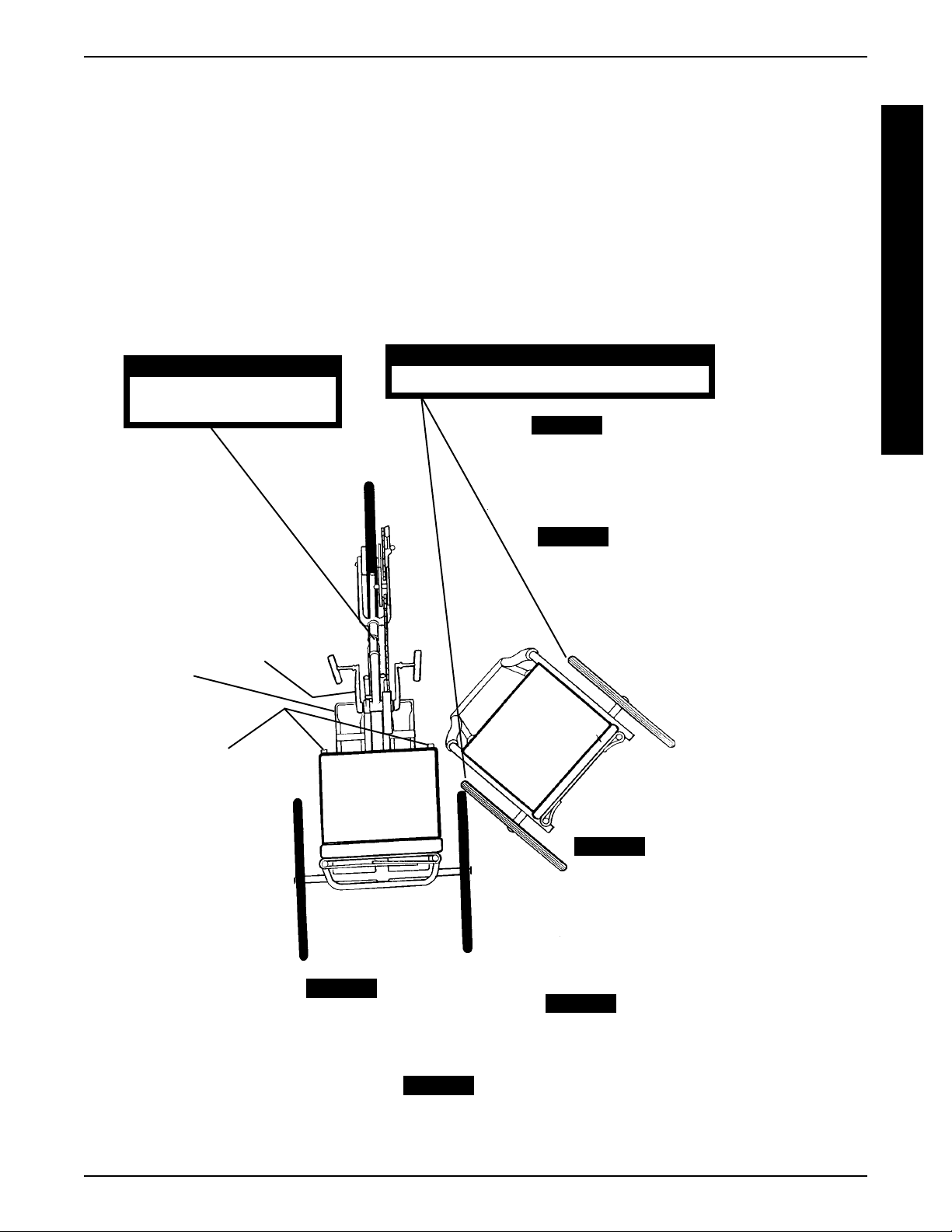
Transferring into/out of the Excelerator
(FIGURE 1)
Stability and Balance
For stability and proper operation of your Excelerator, you
must at all times maintain proper balance. Your Excelerator
should remain upright and stable during normal daily activities when operated correctly.
Invacare recommends using seat positioning straps for
additional safety.
A Note to Excelerator Assistants
When learning assistance techniques for the Excelerator,
have an experienced assistant help you before attempting it alone.
WARNING
Before attempting to transfer IN or OUT of the
Excelerator, every precaution should be taken
to reduce the gap distance. Position the Excelerator on level ground and as close as possible
to the object you are transferring INTO or OUT of.
The parking brake of the Excelerator MUST be engaged and the object you are transferring INTO
or OUT of MUST also be secured before attempting any transfer.
CAUTION
When transferring, position yourself as far back
as possible in the seat. This will prevent damage
to the upholstery.
6
Page 7
GENERAL GUIDELINES
NOTE: This activity may be performed independently
provided you have adequate mobility and upper body
strength.
Position the Excelerator on level ground and as close as
possible along side the object to which you are transferring. Apply parking brake on Excelerator and secure
object that you are transferring into or out of. Shift body
weight onto object with transfer.
During independent transfer, little or no seat platform will
be beneath you. Use a transfer board if at all possible.
WARNING
Parking Brake MUST be
secured.
Wheel Locks MUST be engaged.
PROCEDURE 1
WARNING
STEP 1:
of the wheelchair upholstery closest to
the Excelerator.
Shift body weight to the edge
G
E
N
E
R
A
L
G
U
I
D
E
L
I
N
E
S
Footrest
Hand
Crank
Seat
Frame
STEP 2:
Lift and place LEFT
leg past front frame over center tube.
STEP 3:
Place LEFT hand on
the Excelerator seat frame, NOT
on hand crank.
STEP 6:
Excelerator footrests.
Place both legs onto
STEP 4:
Place RIGHT hand on
the wheelchair frame.
STEP 5:
Lift and shift weight into
Excelerator seat.
FIGURE 1 - TRANSFERRING INTO AND OUT OF THE EXCELERATOR
7
Page 8

PROCEDURE 2
SAFETY INSPECTION/TROUBLESHOOTING/MAINTENANCE
This Procedure Includes the Following:
S
Safety Inspection Checklist Troubleshooting Maintenance
A
SAFETY INSPECTION CHECKLIST
F
E
NOTE: Every six (6) months, take your Excelerator to a qualified technician for a thorough inspection and servicing. Regular
cleaning will reveal loose or worn parts and enhance the smooth operation of your Excelerator. For safe and proper operation, your
T
Excelerator must be cared for just like any other vehicle. Routine maintenance will extend the life and efficiency of your Excelerator.
Y
NOTE: Invacare recommends that the following adjustments be performed by a qualified technician. Initial adjustments should be
I
made to suit your personal body structure and preference. Thereafter follow these maintenance procedures.
N
S
P
E
C
T
O
N
T
R
O
U
B
L
E
S
H
O
O
T
N
G
M
A
N
T
E
N
A
N
C
E
ITEM INITIALLY INSPECT/ INSPECT/ INSPECT/
FRAME
Check for bent or broken frame. Frame damage can cause
other parts to fail. X X X
I
BRAKES (PROCEDURE 8)
Parking Brake - Adjust brake shoes to front rim. Check for
worn or missing shoes. Check for wax or oil on rim. X X X
Cable anchor attached securely to brake arm. X X X
Internal Stopping Brakes - engages easily. X X X
SEAT AND BACK UPHOLSTERY (PROCEDURE 10)
Inspect for rips or sagging. X X
REAR WHEELS (PROCEDURE 4)
Axle nut and wheel mounting nuts are secure. X X X X
No excessive side movement or binding when lifted and spun. X X X
CAUTION: As with any vehicle, the wheels and tires
should be checked periodically for cracks and wear, and
should be replaced.
SPOKES (PROCEDURE 4)
Inspect for bent or broken spokes. X X
All spokes uniformly tight. X X
FRONT WHEEL/FORK (PROCEDURE 5)
Keep axle nuts tight. Wheel should be centered in fork. Keep
wheel bearings adjusted and keep spokes tight and wheel
in proper alignment. X X X
Check rim and fork assembly for damage. X X X
I
CAUTION: As with any vehicle, the wheels and tires
should be checked periodically for cracks and wear, and
should be replaced.
TIRES (PROCEDURE 4)
Inspect for flat spots and wear. Check for proper inflation. X X X
CAUTION: As with any vehicle, the wheels and tires
should be checked periodically for cracks and wear, and
should be replaced.
CHAIN/CHAIN GUARD (PROCEDURE 7)
Check for damage, rust, tension and stretch. Adjust if
necessary. Lubricate each link often (3-in-1 oil or a quality
I
bike lubricant). Check for damage or looseness. X X X
CONTROL CABLES (PROCEDURE 6)
Adjust accordingly. X X X
FRONT FORK (GOOSE NECK) (PROCEDURE 5)
Keep tight and lubricate (All purpose grease). X X X
FOOTREST (PROCEDURE 11)
Check that mounting hardware is tight and footrest secure. X X
Check footrest straps for wetness and/or damage. X X X X
UPHOLSTERY (PROCEDURE 10)
Clean upholstery with light detergent and water. X X
MOUNTAIN DRIVE OPTION (PROCEDURE 12)
Oil Hand crank. X
Adjust bearing play X
ADJUST ADJUST ADJUST
WEEKL Y MONTHLY PERIODICALL Y
8
Page 9
SAFETY INSPECTION/TROUBLESHOOTING/MAINTENANCE
PROCEDURE 2
TROUBLESHOOTING
SLUGGISH WHEEL SQUEAKS LOOSENESS SOLUTIONS
VEERS VEERS TURN OR FLUTTERS AND IN
RIGHT LEFT PERFORMANCE RATTLES EXCELERATOR
XXXX Check tires for correct and
equal pressure.
XXX XCheck for loose axle nuts.
XXCheck spokes and nipples.
XXXCheck chain for proper ten-
sion and adjustment.
XXCheck that goose neck fitt-
ings are secure.
MAINTENANCE
S
A
F
E
T
Y
I
N
S
P
E
C
T
I
O
N
Maintenance Safety Precautions
WARNING
After ANY adjustments, repair or service and BEFORE use, make sure all attaching hardware is tightened securely - otherwise injury or damage may
result.
CAUTION
DO NOT overtighten hardware attaching to the
frame. This could cause damage to the frame tubing.
Suggested Maintenance Procedures
1. Before using your Excelerator, make sure all nuts and
bolts are tight. Check all parts for damage or wear and
replace. Check all parts for proper adjustment.
2. Check parking brake cable and shifter adjustment
cables for proper adjustment and operation. Refer to
PROCEDURES 6 AND 7 of this manual.
3. If equipped, keep quick release axles free of dirt and
lint to ensure positive locking and proper operation. Refer
INSTALLING/ADJUSTING THE REAR WHEEL
to
AND QUICK-RELEASE AXLES - EXCELERATOR
AND LI'L EXCELERATOR in PROCEDURE 4 of this
manual. Oil quick-release axles at least once (1) a month
(3-in-1® oil or equivalent).
WARNING
Do not use the wheelchair unless it has the proper
tire pressure (p.s.i.). DO NOT overinflate the tires.
Failure to follow these suggestions may cause the
tire to explode and cause bodily harm.
4. Recommended tire pressure is listed on the side wall
of the tire. If tire needs replaced, see local bike shop.
CAUTION
As with any vehicle, the wheels and tires should
be checked periodically for cracks and wear,
and should be replaced.
5. The wheels and tires should be checked periodically for cracks and wear, and should be replaced.
6. Check chain for slack and readjust. Refer to
EXCELERATOR / LI'L EXCELERATOR CHAIN ADJUSTMENT in PROCEDURE 7 of this manual.
7. Regularly check for loose spokes in the front and
rear wheels. If loose, have them aligned at your local
bike shop.
8. If equipped, check tension spring for proper operation.
Refer to
SION SPRING INSTALLATION in PROCEDURE 5 of
this manual.
9. Check Upholstery for sagging, rips or tears Refer to
BACK UPHOLSTERY REPLACEMENT or SEAT
UPHOLSTERY REPLACEMENT in PROCEDURE
10 of this manual.
10. Check alignment of front wheel. If it wobbles or takes
too much effort to turn by hand, have it aligned at
your local bike shop.
EXCELERATOR/LI'L EXCELERATOR TEN-
T
R
O
U
B
L
E
S
H
O
O
T
I
N
G
M
A
I
N
T
E
N
A
N
C
E
3-in-1® - Registered trademark of American Home Products
Corporation.
9
Page 10

PROCEDURE 3
ASSEMBL Y PROCEDURES
This Procedure Includes the Following:
Excelerator/Li'l Excelerator Assembly Procedures
A
S
Excelerator XLT/XLT 2000 Assembly Procedures
S
E
M
B
L
Y
P
R
O
C
E
D
U
R
E
S
After ANY adjustments, repair or service and BEFORE use, make sure all attaching hardware is tightened securely - otherwise injury or damage may
result.
DO NOT operate the Excelerator if the hand crank
obstructs your view. If the hand crank obstructs
your view, adjust the hand crank height BEFORE
using the Excelerator - Otherwise injury or damage may occur.
EXCELERATOR/LI'L
EXCELERATOR ASSEMBLY
WARNING
PROCEDURES (FIGURE 1)
NOTE: Invacare recommends that the following procedures be performed by a qualified technician.
T ools required:
Adjustable wrench (10-12-inches)
6, 8 and 9mm wrench
1/8-inch allen wrench
1/2-inch box wrench
Two (2) medium srewdrivers (flathead and phillips)
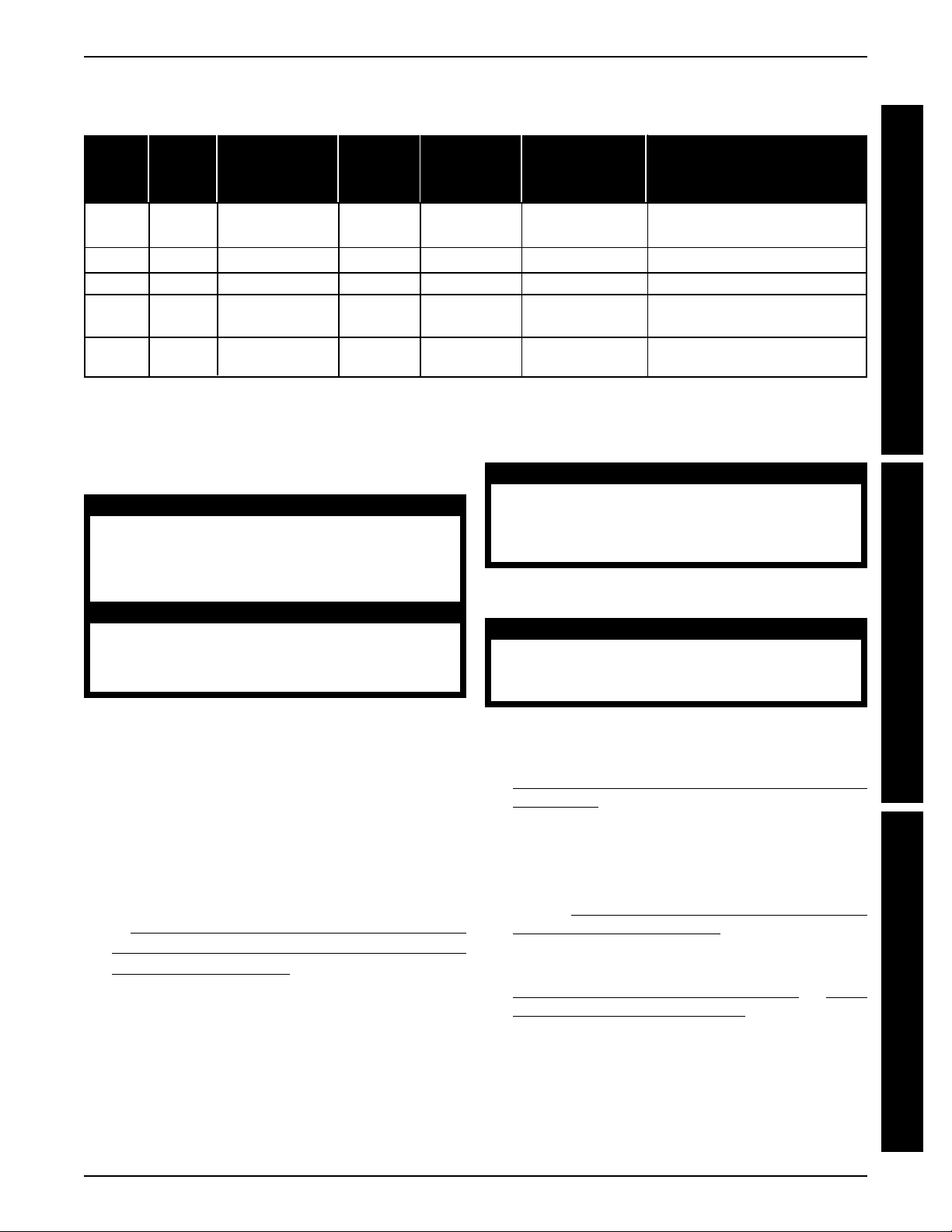
1. Secure and adjust rear wheels (PROCEDURE 4).
2. Secure the fork assembly (PROCEDURE 5).
3. Secure and adjust tension spring (PROCEDURE 5).
4. Secure and adjust hand crank assembly (PROCEDURE 5).
5. Secure and adjust STANDARD three (3) speed shifter
or Seven (7) speed shifter (PROCEDURE 6).
6. Adjust chain (PROCEDURE 7).
7. Tension and adjust cantilever brake cable (Optional
[PROCEDURE 8]).
8. Fasten and adjust parking brake (PROCEDURE 8).
9. Secure and adjust back height (PROCEDURE 9).
10. Secure and adjust seat position/upholstery (PROCEDURE 10).
11. Secure and adjust footrest (PROCEDURE 11).
12. Check that all hardware is tight.
PROCEDURE 9
PROCEDURE 4
PROCEDURE 10
PROCEDURE 6
PROCEDURE 5
PROCEDURE 8
PROCEDURE 6
PROCEDURE 11
FIGURE 1 - EXCELERATOR/LI'L EXCELERATOR ASSEMBLY PROCEDURES
10
Page 11
ASSEMBL Y PROCEDURES
PROCEDURE 3
EXCELERATOR XLT/XLT 2000
ASSEMBLY PROCEDURES
(FIGURE 2)
NOTE: Invacare recommends that the following procedures be performed by a qualified technician.
Tools required:
Adjustable Wrench (10-12-inches)
5, 8 and 32 mm Wrench
3/16-inch Allen Wrench
1/4-inch Allen Wrench
1/2-inch Box Wrench
1/2-inch Socket Wrench
Two (2) Medium Screwdrivers (Flathead and Phillips)
EXCELERA TOR XL T
PROCEDURE 10
PROCEDURE 9
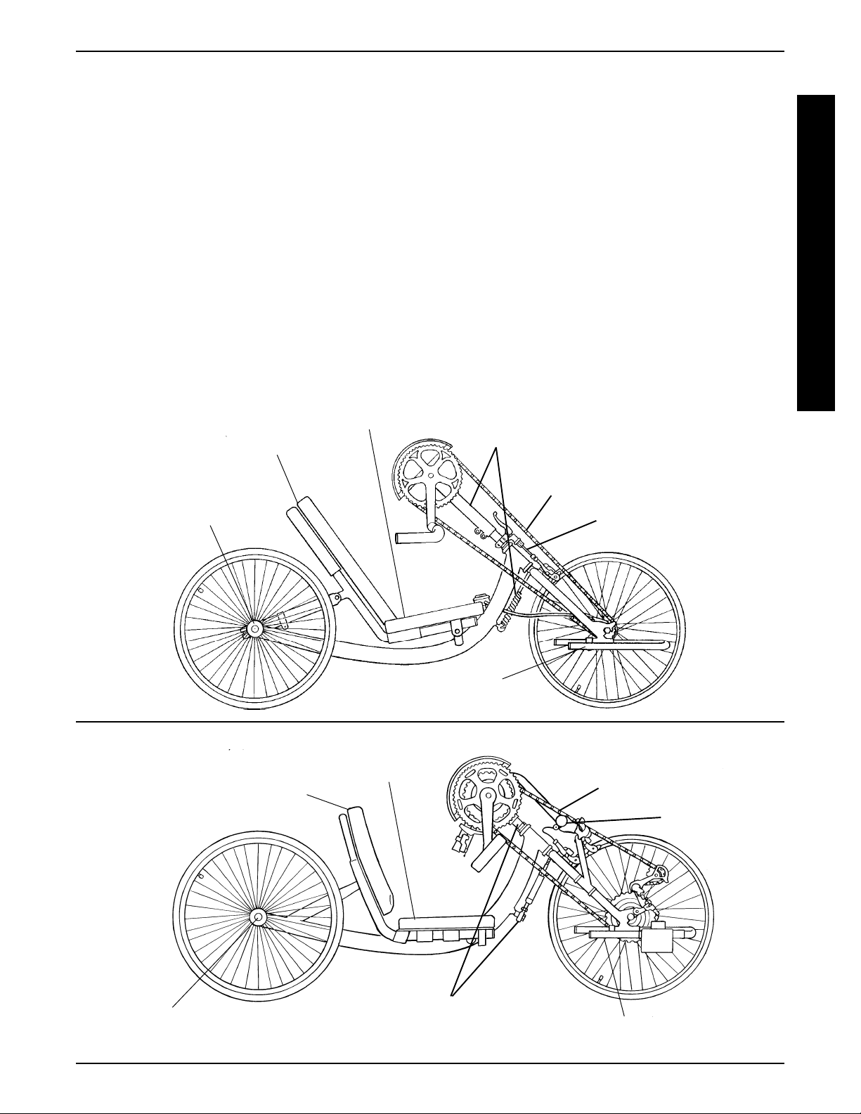
1. Secure and adjust rear wheels (PROCEDURE 4).
2. Adjust hand crank assembly (PROCEDURE 5).
3. Adjust chain (PROCEDURE 7).
4. Adjust the optional cantilever brake cable (PROCEDURE 8).
5. Adjust parking brake (PROCEDURE 8).
6. Adjust back height and/or angle (PROCEDURE 9).
7. Adjust seat position/upholstery (PROCEDURE 10).
8. Adjust footrest (PROCEDURE 11).
9. Check that all hardware is tight.
PROCEDURE 5
A
S
S
E
M
B
L
Y
P
R
O
C
E
D
U
R
E
S
PROCEDURE 4
PROCEDURE 9
PROCEDURE 7
PROCEDURE 8
PROCEDURE 11
EXCELERA TOR XLT 2000
PROCEDURE 10
PROCEDURE 7
PROCEDURE 8
PROCEDURE 4
PROCEDURE 5
PROCEDURE 11
FIGURE 2 - EXCELERA TOR XLT/XLT 2000 ASSEMBLY PROCEDURES
11
Page 12

PROCEDURE 4 REAR WHEELS
This Procedure includes the following:
Installing/Adjusting the Rear Wheels and Quick-
Release Axles
R
Installing the Rear Wheels with Threaded Axle
E
Option - Excelerator XL T/XLT 2000
A
Tire/Tube Replacement and Tuning/Replacement
R
of Spokes
W
Tire Pressure
Determining/Adjusting Toe In/T oe Out
H
Replacing Camber Inserts
E
E
WARNING
S
L
After ANY adjustments, repair or service and BEFORE use, make sure all attaching hardware is tightened securely - otherwise injury or damage may
result.
INSTALLING/ADJUSTING THE
REAR WHEEL AND QUICKRELEASE AXLES (FIGURE 1)
5. Reinstall rear wheel on the Excelerator.
6. Tilt Excelerator onto either rear wheel and spin raised
wheel. It should spin freely with no excessive drag.
7. Repeat procedure for opposite rear wheel.
NOTE: If drag to either side occurs, repeat the procedure until the Excelerator rolls correctly.
INSTALLING THE REAR WHEELS
WITH THREADED AXLES EXCELERATOR XLT/XLT 2000
(FIGURE 2)
1. Apply a small amount of grease onto the axle.
2. Insert the axle into the axle mounting hole on the chair
frame.
3. Securely tighten the axle to the frame.
Axle Mounting
Hole
1/4-inch Allen
Wrench
1. Make sure that the axle receiver hex nut is securely
tightened before installing the rear wheels.
2. Depress detent pin in the quick-release axle and slide
axle through the axle receiver.
3. Release detent pin ensuring that the locking pins are
fully released.
NOTE: Locking pins MUST protrude past the end of the
axle receiver to fully release. Any excessive play MUST
also be eliminated.
4. Increase or decrease end play by adjusting the locknut on the end of the quick-release axle.
WARNING
Make sure detent pin is fully released BEFORE operating the Excelerator, Li'l Excelerator or
Excelerator XL T.
Keep locking pins clean.
Axle Receiver Hex Nut
Locknut
Frame
Axle
FIGURE 2 - INSTALLING THE REAR WHEELS WITH
THREADED AXLES - EXCELERA TOR XL T/XL T 2000
Rear Wheel
TIRE/TUBE REPLACEMENT AND
TUNING/REPLACEMENT OF SPOKES
NOTE: Invacare recommends that these procedures be
performed by a qualified technician.
TIRE PRESSURE
WARNING
DO NOT use the Excelerator unless it has the
proper tire pressure (p.s.i.). DO NOT overinflate the
tires. Failure to follow these suggestions may cause
the tire to explode and cause bodily harm. Tire
p.s.i. is printed on the tire wall.
DETERMINING/ADJUSTING
TOE IN/TOE OUT (FIGURE 3)
Locking Pins
Axle Receiver
FIGURE 1 - INSTALLING/ADJUSTING THE REAR WHEEL
AND QUICK-RELEASE AXLES
Detent Pin
Determining Toe In/Toe Out
1. Inflate all pneumatic tires to recommended tire pressures (listed on the sidewall of the tire).
12
Page 13

PROCEDURE 4REAR WHEELS
2. Measure the distance between the center lines at the
rear and front of the rear wheels at approximately 12inches from the ground/floor (FIGURE 3).
NOTE: For optimum accuracy, perform STEP 2 with the
wheelchair occupied.
3. Determine the difference between the two (2) measurements. If the difference between the two (2)
measurements is GREA TER than 1/2-inch (0
4-inch for maximum rollability), one (1) of two (2)
conditions exists:
a. If the back centerline measurement of the rear
wheels is SMALLER than the front centerline
measurement of the rear wheels, a TOE-OUT
condition exists (FIGURE 3).
b. If the back centerline measurement of the rear
wheels is LARGER than the front centerline
measurement of the rear wheels, a TOE-IN condition exists (FIGURE 3).
4. If the difference between the measurements is greater
than 1/2-inch, correct the toe-in/toe-out condition. Refer to
ADJUSTING TOE-IN/TOE-OUT in this proce-
dure of the manual.
Clamp
Camber
Insert
FRONT OF WHEELCHAIR
Socket Screw
Toe-out
+ 1/
Camber
Bar
Adjusting Toe In/Toe Out
1. Loosen, but do not remove the socket screws and
clamps that secure camber inserts to the camber bar.
2. Slowly rotate the camber insert until the rear wheels
are approximately in a straight line.
3. Securely tighten the socket screws and clamps that
secure the camber inserts to the camber bar.
4. Measure the distance between the center lines at the
rear and front of the rear wheels at approximately 12inches from the ground/floor. Refer to
ING TOE IN/TOE OUT in this procedure of the
manual.
5. Repeat STEPS 1-4 until the toe in/toe out measurement is less than 1/2-inch (0
rollability).
+ 1/4-inch for maximum
DETERMIN-
REPLACING CAMBER INSERTS
(FIGURE 4)
1. Loosen, but do not remove the socket screws and
clamps that secure the camber inserts to the camber
bar.
2. Remove the existing camber insert from the camber
bar.
3. Install the new camber insert into the camber bar.
4. Adjust the toe in/toe out of the wheelchair. Refer to
DETERMINING/ADJUSTING TOE IN/TOE OUT in
this procedure of the manual.
R
E
A
R
W
H
E
E
L
S
Toe-in
Top View of
Wheelchair
Smaller Than
Front
Larger Than Front
FIGURE 3 - DETERMINING/ADJUSTING TOE IN/TOE OUT
13
Frame
Clamp
Camber
Insert
FIGURE 4 - REPLACING CAMBER INSERTS
Socket
Screw
Camber Bar
Page 14

PROCEDURE 5 FORK/SPRING/CRANK
This Procedure includes the following:
EXCELERA TOR/LI'L EXCELERA TOR:
F
O
Fork Assembly Installation
R
K
Tension Spring Installation
/
Hand Crank Assembly Installation
S
EXCELERA TOR XL T/XLT 2000:
P
R
Fork /Crank Assembly Replacement
I
Tension Spring or Road Crown Compensator
N
G
Replacement/Adjustment
/
C
R
A
N
K
After ANY adjustments, repair or service and BEFORE use, make sure all attaching hardware is
tightened securely - otherwise injury or damage
may result.
DO NOT operate the Excelerator if the hand crank
obstructs your view. If the hand crank obstructs
your view, adjust the height BEFORE using the
Excelerator - Otherwise injury or damage may
occur.
WARNING
EXCELERATOR/LI'L
EXCELERATOR FORK ASSEMBLY
INSTALLATION (FIGURE 1)
1. Remove the fork assembly from the packaged container.
2. Slide fork assembly through the opening in the front
frame (Goose Neck) making sure to seat washer
and ball bearing housing.
3. Seat ball bearings on fork assembly.
4. Place locknut over fork assembly and tighten.
5. Tighten locknut setscrews.
EXCELERATOR/LI'L
EXCELERATOR TENSION SPRING
INSTALLATION (FIGURE 1)
NOTE: The tension spring is NOT intended to keep the
Excelerator straight when pedaling but to keep the
Excelerator from leaning excessively to one side or another.
Ball Bearings
Locknut
Goose Neck
Front Frame
Opening
Ball Bearing Housing
Eye Bolt
Washer
Fork Assembly
Tension Spring
Eye Bolt
FIGURE 1 - EXCELERATOR/LI'L EXCELERATOR FORK
ASSEMBL Y/TENSION SPRING INST ALLA TION
Adjustable
Chain Idler
EXCELERATOR/LI'L
EXCELERATOR HAND CRANK
ASSEMBLY INSTALLATION
(FIGURE 2)
1. Remove the chain from the front wheel hub so it moves
with the hand crank assembly.
2. Slide the hand crank assembly over and completely
down the fork stem.
3. Position the chain on the hand crank sprocket assembly and the front wheel hub.
4. Move the hand crank assembly up or down on the
fork stem until you are comfortable with the position
for operational purposes.
NOTE: Positioning of the hand crank assembly loosens
or tightens the chain in an UP/DOWN position.
5. Tighten hex nut to secure the hand crank assembly.
6. Adjust the tautness of the chain by moving the adjustable chain idler IN or OUT.
7. Tighten the hex screw to secure the adjustable chain
idler in place.
1. Tighten eye bolts into fork assembly and front frame.
2. Using a medium flat head screwdriver, hook the tension spring to the fork assembly and front frame eye
bolts.
NOTE: Tension is applied by loosening or tightening the
eye bolts. This should be done before installation of the
tension spring.
Fork
Stem
FIGURE 2 - EXCELERATOR/LI'L EXCELERATOR HAND
CRANK ASSEMBL Y INST ALLA TION
Hex Nut
Step 5
14
Page 15

FORK/SPRING/CRANK PROCEDURE 5
EXCELERATOR XLT/XLT 2000
FORK/CRANK ASSEMBLY
REPLACEMENT (FIGURE 3)
NOTE: Invacare recommends that the following procedure be performed by a qualified technician.
1. Note the position of the crank handles.
STEPS 1, 2, 3, 38, 39 STEPS 6, 36 STEPS 7, 8, 35
Fork
Socket
Screws
Fork
Crank
Handles
Half
Clamp
Socket
Screws
2. Loosen, but do not remove the two (2) socket screws
that secure the crank handles to the existing fork.
3. Slide the crank handles down towards the front wheel.
4. Remove the chain from the crank handles.
5. Remove the crank handles from the existing fork.
6. Remove the two (2) socket screws and half clamp
that secure the brake handle to the existing fork.
7. Remove the socket nut on the BACK of the existing
fork that secures the brake assembly.
Brake
Handle
Fork
Hardware
Socket
Nut
Brake Assembly
F
O
R
K
/
S
P
R
I
N
G
/
C
R
A
N
K
STEPS 9, 34
Fork
Road Crown Compensator
STEPS 13, 14, 27, 28, 29, 30
Non-Turn
Fork
Washer - Must
Be Installed
as Shown
Washer
Front
Cap Nuts
Wheel
STEPS 10, 33
Seat Frame
STEPS 16, 17, 24, 25
Fork
Hex
Bolts,
Locknuts
and
Footrest
Footrest
Clamps
Shifter
STEPS 11, 12, 31, 32
Locknut
Brake
Hex Bolt
Arm
STEPS 5, 18, 19, 20, 21, 22, 23, 37
Crank Handles
Top
Nuts
Bearing
O-Ring
Bottom Bearing
Frame
Fork
Brake
Arm
Clamp
FIGURE 3 - EXCELERA TOR XL T/XLT 2000 FORK/CRANK ASSEMBL Y REPLACEMENT
15
Page 16

FORK/SPRING/CRANKPROCEDURE 5
8. Note brake assembly hardware position and remove
the brake assembly from the existing fork.
F
9. Remove the tension spring or road crown compen-
O
R
K
/
S
P
R
I
N
G
/
C
R
A
N
K
sator from the existing fork. Refer to
XLT/XLT 2000 TENSION SPRING OR ROAD
CROWN COMPENSATOR REPLACEMENT in this
procedure of the manual.
10. Loosen, but do not remove the socket screw that
secures the shifting lever to the seat frame.
11. Remove the hex bolt and locknut that secure the brake
arm to the brake arm clamp.
12. Remove the brake arm clamp from the existing fork.
13. Loosen, but do not remove the two (2) cap nuts that
secure the front wheel to the existing fork.
14. Remove the front wheel from the existing fork.
EXCELERATOR
15. Lay the chain flat.
NOTE: Laying the chain flat will prevent kinks in the chain.
16. Remove the two (2) hex bolts, locknuts and clamps
that secure the footrests to the existing fork.
17. Note the position of the footrests and remove the footrests from the existing fork.
18. Remove the two (2) top nuts that secure the existing
fork to the frame.
19. Note the o-ring and bearing position and remove the
existing fork from the frame.
30. Torque the two (2) cap nuts 260-390 inch-pounds.
31. Install the brake arm clamp onto the new fork.
32. Secure the brake arm to the brake arm clamp with
the hex bolt and locknut. Torque to 22-26 inch-pounds.
33. Reinstall the shifting lever onto the seat frame and
secure with the socket screw.
34. Install the tension spring or road crown compensator
onto the new fork. Refer to
EXCELERATOR XLT/
XLT 2000 TENSION SPRING OR ROAD CROWN
COMPENSATOR REPLACEMENT/ADJUSTMENT
in this procedure of the manual.
NOTE: EXCELERATOR XLT BUILT BEFORE 9/99
ONLY- Make sure the shifting cable is between the spring
and the frame.
35. Install the brake assembly onto the new fork. Refer to
the hardware position noted in STEP 8 and tighten
securely with the socket nut.
36. Install the brake handle and half clamp onto the new
fork and secure with the two (2) socket screws.
37. Slide the crank handles onto the new fork.
NOTE: Make sure the sprocket on the crank handles is in
line with the sprocket on the front wheel.
38. Reinstall the chain onto the crank handle sprocket.
39. Move the crank handle to the position determined in
STEP 1 and tighen the two (2) socket screws securely.
20. Slide the bottom bearing onto the new fork. Refer to
FIGURE 3 for correct orientation.
21. Slide the new fork into the frame.
22. Position the o-ring and bearing on the new fork. Refer to FIGURE 3 for correct orientation.
23. Install the two (2) nuts onto the new fork and tighten
securely. Refer to FIGURE 3 for correct orientation.
24. Position the footrest clamps on the new frame.
25. Install the footrests onto the new fork to the position
noted in STEP 17 and secure with the two (2) hex
bolts and locknuts.
26. Position the chain around the hub of the front wheel.
27. Install the front wheel onto the new fork.
NOTE: Make sure the washer and the non-turn washer
are on the OUTSIDE of the new fork.
28. Line up the projecting ends of the non-turn washer
with the slot in the new fork.
29. Repeat STEPS 27-28 until the projecting ends of the
non-turn washer line up with the slot in the new fork.
EXCELERATOR XLT/XLT 2000
TENSION SPRING OR ROAD
CROWN COMPENSATOR
REPLACEMENT/ADJUSTMENT
NOTE: Excelerator XLTs built before 9/99 have the tension spring. All Excelerator XLTs built after 9/99 have the
road crown compensator.
NOTE: The tension spring or road crown compensator is
NOT intended to keep the Excelerator XLT/XLT 2000
straight when pedaling but to keep the Excelerator XLT/
XLT 2000 from leaning excessively to one side or another.
Tension Spring Replacement/Adjustment
(FIGURE 4)
REMOVING TENSION SPRING.
1. Using a medium flat head screwdriver, unhook the
existing tension spring from fork and frame eye bolt.
16
Page 17

FORK/SPRING/CRANK PROCEDURE 5
ADJUSTING TENSION SPRING.
NOTE: Adjustments should be performed BEFORE
installation of the tension spring.
1. Rotate the frame eye bolt to adjust the tension.
CLOCKWISE - INCREASES tension.
COUNTERCLOCKWISE - DECREASES tension.
INSTALLING TENSION SPRING.
1. Using a medium flat head screwdriver, hook the new
tension spring onto the fork eye bolt and frame eye bolt.
Fork
Fork Eye
Bolt
Frame Eye Bolt
Tension Spring
FIGURE 4 - TENSION SPRING REPLACEMENT/
ADJUSTMENT
Road Crown Compensator Replacement/
Adjustment (FIGURE 5)
4. Rotate the fork to ensure the front wheel is pointing directly forward.
5. Position the fork end of the road crown compensator on the fork bolt.
NOTE: If necessary, lengthen or shorten the road
crown compensator to position the fork end onto the
fork bolt. Refer to the
ADJUSTING procedure in this
section.
6. Secure the road crown compensator to the fork
bolt with the locknut. Tighten securely.
Fork Bolt
Locknut
REMOVED
Frame
Mounting
Hole
Frame
Fork End
Road Crown
Compensator
Frame End
INST ALLED
Bolt
Spacer
F
O
R
K
/
S
P
R
I
N
G
/
C
R
A
N
K
REMOVING ROAD CROWN COMPENSATOR.
1. Remove the locknut securing the fork end of the
road crown compensator to the fork bolt.
2. Remove the fork end of the the road crown compensator from the fork bolt.
3. Remove the bolt and spacer securing the frame
end of the road crown compensator to the frame.
ADJUSTING ROAD CROWN COMPENSATOR.
1. Rotate the fork end of the road crown compensator to adjust the length.
CLOCKWISE - shortens the road crown compensator and pulls the front wheel to the left.
COUNTERCLOCKWISE - lengthens the road crown
compensator and pushes the front wheel to the right.
INSTALLING ROAD CROWN COMPENSATOR.
1. Position the bolt through the frame end of the road
crown compensator.
2. Position the spacer on the bolt.
3. Install the bolt with spacer and road crown compensator into the mounting hole on the frame.
Frame
Fork
Road Crown
Compensator
ADJUSTING
Fork
End
Road Crown Compensator
FIGURE 5 - ROAD CROWN COMPENSATOR
REPLACEMENT/ADJUSTMENT
17
Page 18

SPEED SHIFTERSPROCEDURE 6
This Procedure includes the following:
LI'L EXCELERA TOR:
S
Three (3) Speed Shifter Cable Installation
P
Three (3) Speed Shifter Cable Adjustment
E
EXCELERA TOR/EXCELERA TOR - XL T :
E
D
Seven (7) Speed Shifter Cable Installation
Seven (7) Speed Shifter Cable Adjustment/
S
Replacement
H
I
F
T
E
R
S
After ANY adjustments, repair or service and BEFORE use, make sure all attaching hardware is tightened securely - otherwise injury or damage may
result.
LI'L EXCELERATOR - THREE (3)
SPEED SHIFTER CABLE
WARNING
INSTALLATION (FIGURE 1)
NOTE: The THREE (3) SPEED Shifter Cable runs from
the LEFT-SIDE of the FRONT FRAME to its mounting
position on the HAND CRANK Assembly Shaft.
1. Run the cable from the left-side of the fork assembly
to mounting position just below the hand crank assembly.
2. Attach the three (3) speed cable to the hand crank
assembly extension.
3. Secure with hardware provided.
FIGURE 1 - LI'L EXCELERATOR THREE (3) SPEED
SHIFTER CABLE INSTALLATION
LI'L EXCELERATOR - THREE (3)
SPEED SHIFTER CABLE
ADJUSTMENT
CAUTION
DO NOT ride the Excelerator if the hub is out of
adjustment. This will damage the internal parts
and cause hub to malfunction.
3. Shift gears to check for correct adjustment.
NOTE: If gears do NOT shift, increase cable tension and
retest proper shifting of gears. If the chain skips a gear,
loosen the cable tension until correct operation is achieved.
CAUTION
DO NOT overtighten the cables. Doing so may
cause the cable to break. If PROCEDURE A does
NOT solve the problem, take your Li'l Excelerator
to an authorized Invacare Dealer or qualified
technician for proper adjustment.
NOTE: Shift gears when pedals are stationary or when
minimum amount of pedaling is being done to avoid wear
on rotating parts of hub.
Clamp
Hex Nut
Cable
FIGURE 2 - LI'L EXCELERATOR THREE (3) SPEED
SHIFTER CABLE ADJUSTMENT
Procedure B (FIGURE 3)
NOTE: If the following procedure does not enable all three
(3) gears, contact a qualified technician or Invacare for
assistance.
1. Ensure that the indicator chain is fully screwed into
the axle. Turn back a maximum of half a turn.
2. Check that the indicator chain runs freely through the
indicator protector if fitted.
3. Select third gear and loosely connect the cable adjuster onto the indicator coupling.
4. Select second gear position on the gear control. Looking through the window in the right-hand axle nut,
turn the cable adjuster until the end of the indicator is
exactly level with the end of the axle.
5. Tighten the locknut against the adjuster.
Indicator Protector
Right- Hand
Indicator Chain
Indicator Coupling
Locknut
Cable Adjuster
Axle
Axle Nut
S
P
E
E
D
S
H
I
F
T
E
R
S
Procedure A (FIGURE 2)
1. Loosen the hex nut.
2. Using a pair of pliers, pull cable to increase tension.
Retighten hex nut.
Indicator Chain
FIGURE 3 - LI'L EXCELERATOR THREE (3) SPEED
INDICATOR CHAIN ADJUSTMENT
18
Page 19

PROCEDURE 6SPEED SHIFTERS
EXCELERATOR/EXCELERATOR
XLT - SEVEN (7) SPEED SHIFTER
CABLE INSTALLATION (FIGURE 4)
S
P
NOTE: The SEVEN (7) SPEED Shifter Cable runs from
E
the RIGHT-SIDE of the FRONT FRAME to its mounting
E
position on the HAND CRANK Assembly Shaft.
D
1. Run the cable from the right-side of the fork assem-
S
H
I
F
T
bly to mounting position on the left side just below the
hand crank assembly.
2. Attach the seven (7) speed cable to the hand crank
assembly extension.
3. Secure with hardware provided.
E
R
Shifter Cable
S
FIGURE 4 - EXCELERA TOR/EXCELERATOR XLT SEVEN
(7) SPEED SHIFTER CABLE INST ALLATION
EXCELERATOR/EXCELERATOR
XLT SEVEN (7) SPEED SHIFTER
ADJUSTMENT/REPLACEMENT BEFORE 1997 ONLY (FIGURE 5)
NOTE: Excelerator/Excelerator XLTs manufactured AFTER 1997 are equipped with SHIMANO hubs. If equipped
with a SHIMANO hub, it MUST be serviced and adjusted
by a qualified technician.
NOTE: QUALIFIED TECHNICIANS ONLY - Contact
Invacare, 1-800-532-8677 for complete SHIMANO hub
instructions.
NOTE: There is no cable adjustment for the seven (7)
speed shifter cable. Loosening the knurled screw will enable you to pull the gear box from the hub axle.
It is recommended that you take your Excelerator to a
qualified technician for any shifter adjustment.
If adjustment or replacement of internal parts is required,
i.e., won't shift into ALL seven (7) gears, perform the following replacement:
1. Ensure that the hub and shifter are properly installed.
NOTE: Shifter is installed with a 4 mm hex key to a torque
of 1.8 to 2.1 ft. lbs.
2. Loosen knurled screw and pull gearbox (clickbox) from
the hub axle.
3. Run the cable and clickbox along the frame and above
the bottom bracket until it reaches the rear axle.
Shifter
4. Ensure that there are no extreme bends in the cable
and there is ample slack for the handlebars to turn
without binding the cable.
5. Use a light oil and lubricate shift rod and the shift tube.
CAUTION
Ensure that the inner lug of the guiding rib is run into
the shift tube slot until it snaps into place.
6. Push the rod and tube into the drive side of the axle as
far as it will go. The shift rod should fit inside of the shift
tube.
7. Position the shifter in gear number one.
8. Push the RED adjusting sleeve (guiding rib first) over
the axle.
9. Position the guiding rib above the axle and slide it onto
the clickbox.
NOTE: The guiding rib complete MUST be seated into the
clickbox housing groove.
10. Ensure that the guiding rib fits into the slot in the top of
the clickbox.
CAUTION
Ensure that knurled screw is secure.
11. Finger tighten knurled screw on clickbox.
12. If more technical assistance is required, contact the
manufacturer direct at (800) 346-2928.
13. To maintenance, periodically lubricate the shift rod
and shift tube.
Bracket
Gearbox
(Clickbox)
Adjusting
Sleeve
(Insert into
slot in
clickbox
opening)
Knurled
Screw
FIGURE 5 - EXCELERA TOR/EXCELERATOR XLT SEVEN
(7) SPEED SHIFTER CABLE ADJUSTMENT/
REPLACEMENT - SACHS HUB ONLY
Internal Peg
(Align with
slot in shift
tube opening)
Shift Tube
(EXCELERATOR
ONLY)
Guiding Rib
Axle Bore
Shift Rod
Slot for
Internal
Peg
Groove for
Knurled Screw
Hub
Axle
S
P
E
E
D
S
H
I
F
T
E
R
S
19
Page 20

CHAINPROCEDURE 7
This Procedure includes the following:
EXCELERA TOR/LI'L EXCELERA TOR:
Chain Installation w/Seven (7) Speed Hub
Chain Adjustment
Chain Stay Adjustment
C
H
A
EXCELERA TOR XLT/XLT 2000:
Chain Adjustment
Chain Installation w/Twenty-Four (24) or T wentySeven (27) Speed Cassette
I
N
Chain MUST be tight. If noisy, loosen. After chain
is assembled, start in first gear and on straightaway.
After ANY adjustments, repair or service and BEFORE use, make sure all attaching hardware is tightened securely - otherwise injury or damage may
result.
WARNING
EXCELERATOR/ LI'L EXCELERATOR
/CHAIN INSTALLATION W/SEVEN (7)
SPEED HUB (FIGURE 1)
5. Place chain over the top of the bottom chain tensioner.
6. Attach the chain together using the master link (w/
clip) provided.
EXCELERATOR/LI'L EXCELERATOR
CHAIN ADJUSTMENT
1. Move the hand crank assembly up and down on the
fork stem until you are comfortable with the position
for operational purposes (PROCEDURE 2).
NOTE: Positioning of the hand crank assembly loosens
or tightens the chain in an UP/DOWN position.
2. Tighten the hex screw to secure the hand crank assembly (PROCEDURE 2).
3. Adjust the tautness of the chain by moving the adjustable chain idler IN or OUT (PROCEDURE 2).
4. Tighten the hex screw to secure the adjustable chain
idler in place (PROCEDURE 2).
EXCELERATOR CHAIN STAY
ADJUSTMENT (FIGURE 2)
C
H
A
I
N
1. Spread the chain out flat and run it over the BOTTOM chain tensioner upwards to the hand crank
sprocket assembly.
2. Position chain over the hand crank assembly sprocket.
NOTE: It may be necessary to turn the hand crank in a
clockwise motion to position the chain on the sprocket.
3. Run the chain over the top chain tensioner.
4. Position the chain around the wheel sprocket and
back up towards the bottom chain tensioner.
Chain
Tensioners
Step 2
Hand Crank
Sprocket Assembly
Wheel Sprocket
FIGURE 1 - EXCELERATOR / LI'L EXCELERATOR/
CHAIN INSTALLATION W/SEVEN (7) SPEED HUB
Top Chain
Tensioner
Bottom
Chain
Tensioner
Step 4
1. Loosen button screw and adjust bracket upward.
Retighten button screw.
Button
Screw
Bracket
FIGURE 2 - EXCELERATOR CHAIN STAY ADJUSTMENT
EXCELERATOR XLT/XLT 2000
CHAIN ADJUSTMENT (FIGURE 3)
1. Loosen, but do not remove the two (2) socket screws
that secure the crank handles to the fork.
2. Slide the crank handles up and/or down until the
proper tension on the chain is achieved.
NOTE: The proper chain tension will be approximately 1/
2-inch of chain slack.
NOTE: If crank is in desired position but chain tension is
not correct, links must be added to or removed from the
chain to correct the tension.
3. Tighten the two (2) socket screws that secure the
crank handles to the fork securely.
20
Page 21

CHAIN PROCEDURE 7
Step 5
Crank
Handles
Hand Crank Sprocket
Fork
Assembly
C
H
A
I
N
Socket
Screws
FIGURE 3 - EXCELERATOR - XLT CHAIN ADJUSTMENT
C
H
A
I
N
EXCELERATOR XLT/XLT 2000
CHAIN INSTALLATION - TWENTYFOUR (24) OR TWENTY-SEVEN (27)
SPEED CASSETTE (FIGURE 4)
1. Spread the chain out flat and run it around the chain
ring on the crank and the sprocket on the hub.
NOTE: It may be necessary to turn the hand crank in a
clockwise motion to position the chain on the small
sprocket.
2. Ensure that crank assembly is loosened and movable.
3. Lift UP on the chain derailleur and thread the chain
under the derailleur.
4. Thread the chain around the wheel sprocket.
5. Run the chain around the BOTTOM of the wheel
sprocket and back up towards the hand crank
sprocket.
6. Attach the chain together using the master link (w/
clip) provided.
7. To tension chain, refer to
2000 FORK/CRANK ASSEMBLY REPLACEMENT
in PROCEDURE 5 of this manual.
EXCELERATOR XLT/XLT
Step 3
Step 4
Chain Derailleur and
Wheel Sprocket
FIGURE 4 - EXCELERA TOR XL T/XLT 2000 CHAIN
INST ALLA TION- TWENTY-FOUR (24) OR TWENTY-
SEVEN (27) SPEED CASSETTE
21
Page 22

P ARKING BRAKEPROCEDURE 8
This Procedure includes the following:
Using Parking Brake
P
Parking Brake Adjustment/Replacement
A
R
K
N
G
After ANY adjustments, repair or service and BE-
I
FORE use, make sure all attaching hardware is tightened securely - otherwise injury or damage may
result.
WARNING
USING PARKING BRAKE (FIGURE 1)
B
NOTE: The parking brake on the Excelerator, Li'l
R
Excelerator and Excelerator XLT is factory installed. No
A
installation is necessary.
K
E
1. To engage the parking brake, squeeze the handle
and push in the stop button on the side of the parking
brake or move stop lever to the highest position.
2. To disengage the parking brake, release the handle.
PARKING BRAKE ADJUSTMENT/
REPLACEMENT (FIGURE 1)
Adjustment
CABLE.
1. Loosen the hex nut and turn the adjuster barrel clockwise (tighten) or counterclockwise (loosen) to adjust
the cable. Retighten hex nut.
BRAKE PADS.
1. Adjust the brake pad assembly so that when the parking brake is engaged the brake pads rest solely on
the rim of the wheel.
Replacement
PARKING BRAKE PADS.
1. Remove the mounting nuts and replace brake pads.
2. Secure with existing hardware and adjust.
PARKING BRAKE.
WARNING
Replacement of the parking brake MUST be
performed by a qualified technician.
P
A
R
K
I
N
G
B
R
A
K
E
WARNING
Before using your particular Excelerator,
inspect the parking brake for proper operation.
Rim of Wheel
Brake
Pads
TO ENGAGE: Squeeze
Handle Closed and
Push in Stop Button or
Move Lever to Stop
Position.
TO DISENGAGE:
Squeeze Handle
Closed until Stop
Button Releases, Then
Release Handle
TO ENGAGE: Squeeze
Handle Closed and Push in
Stop Button or Move Lever to
Stop Position.
TO DISENGAGE: Squeeze
Handle Closed until Stop
Button Releases, Then
Release Handle
Stop Button
Brake Pads
EXCELERATOR/LI'L EXCELERATOR EXCELERATOR XLT
FIGURE 1 - PARKING BRAKE INSTALLATION/ADJUSTMENT/REPLACEMENT
22
Page 23

BACK/SEAT PROCEDURE 9
This Procedure includes the following:
Back Height Adjustment (Adjustable Backs Only)
Sliding Seat Adjustment
Excelerator XL T/XLT 2000 Back Angle Adjustment
WARNING
After ANY adjustments, repair or service and BEFORE use, make sure all attaching hardware is tightened securely - otherwise injury or damage may
result.
BACK HEIGHT ADJUSTMENT
(ADJUSTABLE BACKS ONLY)
(FIGURE 1)
1. Unlatch the two (2) fastening flaps that secure the top
of the back upholstery to the back canes.
WARNING
Push pin MUST protrude thr ough hole in back cane.
Ensure that both back cane inserts are at the same
height BEFORE reassembling the chair.
2. Press the push pin on the back cane insert tube in and
adjust the back height to one (1) of three (3) heights
depending on original back height.
4. Secure the top of the back upholstery to the fastening
flaps ensuring the top of the back upholstery is even
with the top of the back canes.
SLIDING SEAT ADJUSTMENT
(FIGURES 2 AND 3)
Excelerator/Li'l Excelerator (FIGURE 2)
NOTE: The seat is supported on adjustment rails to
allow forward/rearward adjustment. The adjustment
lever is located on the underside of the seat, at the
front left.
1. Activate parking brake.
2. Grasp forward/rearward adjustment lever and push
it to the right and slide seat forward or rearward.
3. Ensure that seat is properly engaged into the seating
position you desire by "jiggling" the seat, making sure
that the seat engages into the locking notch and adjustment lever returns to its original forward facing
position.
NOTE: User need not be in seat to slide seat forward
or rearward.
REPLACEMENT.
1. Remove the locknuts, bolts, and coved spacers
from both sliding seat rail brackets.
2. Remove sliding seat and seat rails from brackets.
B
A
C
K
/
S
E
A
T
3. Reinstall the fastening flaps onto the back canes, ensuring the fastening strips face towards the front of
the Excelerator.
NOTE: The fastening flap with the
left back cane.
Top of Back
Upholstery
Fastening Flaps
Back Canes
Cane
Insert
Push
Pin
Back
Invacare
logo is for the
Seat
Back
Seat Rails
Adjustment Lever
Seat Rail
Locknuts
and
Threaded
Studs (Both
Sides)
Seat Rail Bracket Locknuts, Bolts, and
Coved Spacers (Both Sides)
FIGURE 1 - BACK HEIGHT ADJUSTMENT
(ADJUSTABLE BACKS ONLY)
FIGURE 2 - SLIDING SEAT ADJUSTMENT -
EXCELERATROR/LI'L EXCELERATOR
23
Page 24

BACK/SEATPROCEDURE 9
3. Remove the locknuts from the threaded studs from
seat rails on both sides of seat.
4. Remove seat from seat rails.
5. Reverse STEPS 3-4 to install NEW seat onto seat
B
A
C
K
/
S
E
A
T
rails.
6. Reverse STEPS 1-2 to install sliding seat and seat
rails onto the seat frame.
Excelerator XLT/XLT 2000 (FIGURE 3)
1. Activate parking brake.
2. Loosen, but do not remove the six (6) socket screws
that secure the seat frame to the handcycle frame.
NOTE: There are three (3) socket screws on the right
and left side of the handcycle.
3. Loosen, but do not remove the hex bolts and locknuts that secure the two (2) seat angle adjustment
clamps to the rear seat supports.
NOTE: There is one (1) clamp on the right and left
side of the handcycle.
6. Tighten the hex bolts and locknuts that secure the
two (2) seat angle adjustment clamps to the rear seat
supports securely.
EXCELERATOR XLT/XLT 2000
BACK ANGLE ADJUSTMENT
(FIGURE 4)
1. Activate parking brake.
2. Loosen, but do not remove the four (4) rear socket
screws that secure the seat frame to the handcycle
frame.
NOTE: There are two (2) socket screws on the right and
left side of the handcycle.
3. Loosen, but do not remove the hex bolts and locknuts that secure the two (2) seat angle adjustment
clamps to the rear seat supports.
NOTE: There is one (1) clamp on the right and left side of
the handcycle.
4. Perform one (1) of the following:
4. Perform one (1) of the following:
A. Moving the seat rearward - While lifting up on
the back support tubes, push the seat rearward
to the desired position.
B. Moving the seat forward - While pushing
down on the back support tubes, pull the seat
forward to the desired position.
5. Tighten the six (6) socket screws that secure the
seat frame to the handcycle frame securely.
Seat Angle Adjustment Clamps
Seat Frame
A. Increasing Back Angle - While lifting up on the
back support tubes, pull the seat upward to the
desired position.
B. Decreasing Back Angle - While pushing down
on the back support tubes, push the seat down
to the desired position.
5. Tighten the three (3) socket screws that secure the
seat frame to the handcycle frame securely.
6. Tighten the hex bolts and locknuts that secure the
two (2) seat angle adjustment clamps to the rear seat
supports securely.
Seat Angle Adjustment Clamps
Seat
Socket Screws
FIGURE 3 - SLIDING SEA T ADJUSTMENT -
EXCELERA TROR XLT/XLT 2000
Handcycle Frame
Socket
Screw
Socket
Screws
FIGURE 4 - EXCELERA TROR XL T/XL T 2000 BACK
ANGLE ADJUSTMENT
Handcycle Frame
24
Page 25

PROCEDURE 10UPHOLSTERY
This Procedure includes the following:
Seat Upholstery Replacement
Back Upholstery Replacement
W ARNING
After ANY adjustments, repair or service and BEFORE
use, make sure all attaching hardware is tightened
securely - otherwise injury or damage may result.
Upholstery MUST be inspected BEFORE each use.
Exposure to moisture (ie.- wet weather or puddles)
will damage fastening straps/flaps/strips. DO NOT
operate excelerator if upholstery is wet or damaged, otherwise severe injury may occur.
SEAT UPHOLSTERY REPLACEMENT
(FIGURE 1)
1. Remove seat cushion and back upholstery from chair.
2. Unlatch the four (4) fastening flaps that secure the
seat upholstery to the seat frame.
3. Remove the existing seat upholstery.
4. Install the new seat upholstery making sure that the
three (3) fastening flaps that are in close proximity to
one another are to the rear of the seat frame.
5. Secure the four (4) fastening flaps together.
6. Reinstall back upholstery and seat cushion onto chair.
Back Upholstery
Large
Strap
Toward
Rear of
Seat
Frame
Towards
Front of
Chair
4. Install the new back upholstery onto the wheelchair.
5. Securely latch the fastening flaps on the bottom of
the new back upholstery to the back canes.
Back Upholstery
Fastening
Flap
Fastening
Flap
Back
Canes
FIGURE 2 - BACK UPHOLSTERY REPLACEMENT -
ALL EXCELERA TORS EXCEPT XL T/XLT 2000
NARROW BACK
EXCELERATOR XLT/XLT 2000 Narrow Back
(FIGURE 3)
1. Pull the back cushion off the back frame.
2. Align the fastening strips on the back frame with
the fastening strips on the new back cushion.
3. Press the back cushion firmly against the back
frame to secure.
U
P
H
O
L
S
T
E
R
Y
Three (3) Seat Upholstery Fastening Straps
Towards Rear of Seat Frame
FIGURE 1 - SEAT UPHOLSTERY REPLACEMENT
BACK UPHOLSTERY REPLACEMENT
All Excelerators Except XLT/XLT 2000
Narrow Back (FIGURE 2)
1. Unlatch the two (2) fastening flaps that secure the
bottom of existing back upholstery to the back canes.
2. Unlatch the top of the existing back upholstery.
3. Lift up on the existing back upholstery and remove
from the wheelchair.
25
Back
Frame
Fastening Strips
FIGURE 3 - EXCELERA TOR XL T/XL T 2000
Back
Cushion
Page 26

FOOTRESTPROCEDURE 11
This Procedure includes the following:
EXCELERA TOR LI'L EXCELERA TOR:
Footrest Adjustment/Replacement
EXCELERA TOR - XLT/XLT 2000: Footrest and Leg
Guard Replacement
F
O
Using/Replacing Footrest Strap
O
R
E
S
T
After ANY adjustments, repair or service and BEFORE use, make sure all attaching hardware is tightened securely - otherwise injury or damage may
T
result.
WARNING
EXCELERATOR/LI'L EXCELERATOR
FOOTREST ADJUSTMENT/
REPLACEMENT (FIGURE 1)
NOTE: Range of the Footrest is 0 to 4-1/2-inches.
Adjusting Footrest Height:
Replacing Individual Footplates
1. Remove the two (2) button screws and locknuts that
secure the footrests to the footplate clamps.
2. Align new footplates on the footplate clamps at the desired depth.
3. Line up the mounting holes in the footplates with the
mounting holes in the footplate clamps.
4. Install the button screws into the mounting holes and
tighten securely with the locknuts.
Height Adjustment
Socket
Screws
Footplate
1. Loosen the socket screws on both footrests.
2. Slide the footplate up or down to desired height.
3. Retighten the socket screw that secures the footplate.
4. Secure straps over top of feet before using your
Excelerator.
Adjusting Footrest Angle
1. Loosen the button screws and locknuts that secure
the half clamps to the footrest weldment.
NOTE: The footplate clamps are located under the
footplates.
2. Position footplates to an appropriate angle for user.
3. Securely tighten the button screws and locknuts that
secure the half clamps to the footrest weldment.
Adjusting Footrest Depth
1. Remove the two (2) button screws and locknuts that
secure the footplates to the half clamps.
2. Adjust the footplates to one (1) of five (5) depths.
Depth Adjustment
Button
Screws
Footplate
Locknuts
Angle Adjustment or Replacement
Footplate
Button Screws
3. Line up the mounting holes in the footplates with the
mounting holes in the footplate clamps.
4. Install the button screws into the mounting holes and
tighten securely with the locknuts.
Locknuts
FIGURE 1 - FOOTREST ADJUSTMENT/REPLACEMENT
26
Page 27

FOOTREST PROCEDURE 11
EXCELERATOR XLT/XLT 2000
FOOTREST AND LEG GUARD
REPLACEMENT (FIGURE 2)
Footrest
1. Note the position of the existing footrest.
2. Remove the hex bolt and locknut that secure the existing footrest to the fork.
3. Remove the existing footrest from the clamp on the
fork.
4. Slide the new footrest into the clamp on the fork to
the position noted in STEP 1.
5. Reinstall the hex bolt and locknut. Tighten securely.
6. Repeat STEPS 1-5 for the opposite footrest, if necessary.
Leg Guard
1. Loosen the two (2) allen screws on each mounting clamp.
2. Position each mounting clamp onto the fork under
the brake cable as shown in FIGURE 2.
Fork
Clamp,
Hex Bolt
and
Locknut
Footrest Replacement
F
O
O
T
R
E
S
T
Footrest
Leg Guard Replacement
Fork
NOTE: The leg guard should surround, but not touch
the REAR of the front tire.
3. Tighten the two (2) allen screws on each mounting
clamp securely.
Brake
Cable
Rear of
Front
Tire
Leg Guard
FIGURE 2 - EXCELERA TOR XLT/XLT 2000 FOOTREST
AND LEG GUARD REPLACEMENT
Allen
Screws
Mounting
Clamp
27
Page 28

PROCEDURE 11 FOOTREST
EXCELERATOR XLT/XLT 2000 USING/REPLACING FOOTREST
STRAP
WARNING
F
O
O
T
R
E
S
T
Footrest straps MUST be inspected BEFORE each
use. Exposure to moisture (ie.- wet weather or
puddles) will damage fastening strips. Footrest
strap will not hold feet securely in footrest if fastening strips are damaged. DO NOT operate
excelerator if footrest straps are wet or damaged,
otherwise severe injury may occur.
Always wear shoes and securely strap feet in
using straps provided. Severe injury may occur if feet are not secured while the Excelerator
is in motion.
Using Footrest Strap (FIGURE 3)
1. Place feet in footrests.
2. Secure feet to footrest strap using small fastening
straps.
Footrest
3. Firmly connect the hook and loop portion of the
footrest strap to secure the footrest strap to the
inner footrest tube as shown in DETAIL "A".
4. Wrap end of footrest strap over and around the
outer footrest tube and under the inner footrest
tube as shown in DETAILS "A" and "B".
5. Press the end of the footrest strap against the
portion of the footrest strap installed onto the inner footrest tube as shown in DETAIL "B".
6. Ensure the footrest strap is firmly attached to the
loop fastening strip on the outer footrest tube.
DET AIL "A"
Footrest Strap Loop
Portion
(STEP 3)
Footrest Strap
Hook Portion
(STEP 3)
Small
Fastening
Straps
Fastening
Straps
Footrest
Strap
FIGURE 3 - USING FOOTREST STRAP
Replacing Footrest Strap (FIGURE 4)
1. Pull apart fastening straps securing existing footrest strap to footrest.
2. Position the footrest strap around the inner footrest tube as shown in DETAIL "A".
NOTE: The small fastening straps should face UP.
Inner Footrest
Tube
End of Footrest Strap (STEPS 4 AND 5)
Inner Footrest
Tube
Outer Footrest
Tube
DET AIL "B"
Outer Footrest
Tube
End of Footrest
Strap (STEP 4)
Fastening Strip
(STEP 6)
Loop
28
FIGURE 4 - REPLACING FOOTREST STRAP
Page 29

OPERATION PROCEDURE 12
This Procedure includes the following:
Hand Crank Assembly
Shifting Gears
Backing Up/Braking/Parking Brake
Steering/Cornering
Mountain Drive Option
WARNING
After ANY adjustments, repair or service and BEFORE use, make sure all attaching hardware is tightened securely - otherwise injury or damage may
result.
HAND CRANK ASSEMBLY
NOTE: For Installation or Adjustment of the Hand Crank
Assembly, refer to PROCEDURE 5 in this manual.
NOTE: Adjust the seat to fit your particular requirements
for a comfortable position when operating the Excelerator.
Refer to PROCEDURE 9 in this manual.
The hand crank assembly is used for propelling and steering of the Excelerator. At least one (1) hand MUST be on
the hand crank assembly at all times.
SHIFTING GEARS
Li'l Excelerator (Three [3] Speed)
Excelerator (Seven [7] Speed)
To shift gears, hold onto the hand crank assembly with
one (1) hand, continue pedaling, but ease pressure on
the pedals and select the gear required. If the Excelerator
is stationary, simply select gear required. The neutral position is constant except when pedaling forward or applying the brakes.
Excelerator XLT Twenty-four (24) Speed
(FIGURE 2)
To shift gears, you MUST turn the crank forward with the
chain under some tension while the bike is moving. DO
NOT attempt to shift gears while bike is stationary. Shifting the chain towards the centerline of the handcycle is
for climbing/accelerating and is called a downshift. Moving the chain out or away from the centerline of the
handcycle is for speed and is called an upshift.
There are two (2) grips installed on the seat rails. The
RIGHT grip has eight (8) speeds and the LEFT grip has
three (3) speeds.
1. Rotate the RIGHT grip until the indicator points to
a higher number.
2. Perform one (1) of the following:
A. INDICATOR POINTS TO "8" - Rotate the
LEFT grip until the indicator points to a higher
number. Rotate the RIGHT grip until the indicator points to "1".
B. INDICATOR POINTS TO "1-7" - Repeat
STEP 1 until desired gear is achieved.
3. Repeat STEPS 1-2 until the desired gear is
achieved.
4. To downshift, reverse STEPS 1-3.
O
P
E
R
A
T
I
O
N
Excelerator/Excelerator XLT (Seven [7]
Speed) (FIGURE 1)
1. Perform one (1) of the following:
A. UPSHIFT - Push the shifting lever towards the
indicator and release. Repeat until the desired
gear is obtained.
B. DOWNSHIFT - Push shifting lever down and
away from the indicator. Repeat until the desired
gear is obtained.
UPSHIFT
Indicator
DOWNSHIFT
Shifting
Lever
FIGURE 1 - SHIFTING GEARS - EXCELERA TOR/
EXCELERATOR XLT (SEVEN [7] SPEED)
Indicator
Seat
Rail
FIGURE 2 - EXCELERA TOR XLT TWENTY-FOUR (24)
SPEED
Numbers
29
Grip
Page 30

OPERATIONPROCEDURE 12
Excelerator XLT 2000 Twenty-seven (27) Speed
Cassette (FIGURE 3)
To shift gears, you MUST turn the crank forward with the
chain under some tension while the bike is moving. DO
NOT attempt to shift gears while bike is stationary. Shift-
O
ing the chain towards the centerline of the handcycle is
P
for climbing/accelerating and is called a downshift. Mov-
E
ing the chain out or away from the centerline of the
R
handcycle is for speed and is called an upshift.
A
1. Perform one (1) of the following:
T
I
O
N
A. UPSHIFT - Press the shifter handle DOWN and
release. Repeat until the desired gear is obtained.
B. DOWNSHIFT - Press the brake handle DOWN
and release. Repeat until the desired gear is obtained.
NOTE: The Left shifter handle operates the top derailleur and the Right shifter handle operates the bottom derailleur.
DET AIL "A" - UPSHIFTING
Press Here
and
Release
BACKING-UP
Use the rear wheels (i. e. like a manual wheelchair) to
backup. When backing up keep the front wheel straight.
BRAKING
Reversing Drum Brakes - Seven (7) Speed ONLY
Use the brakes intermittently on your Excelerator cycle to
bring it to a complete stop. Apply by pedaling in reverse.
Hand Brakes - Twenty-Four (24) and TwentySeven (27) Speed ONLY (FIGURE 4)
1. Squeeze brake handle(s) as needed to slow or
come to a complete stop.
2. Release when desired speed is acheived.
Squeeze
Brake
Handle
Shifter
Handle
Upper
Derailleur
DET AIL "B" - DOWNSHIFTING
Brake
Handle
Press Here and
Release
FIGURE 3 - EXCELERATOR XL T 2000 TWENTY-SEVEN
(27) SPEED CASSETTE
Lower
Derailleur
NOTE: Twenty-seven (27) speed hand brake shown.
FIGURE 4 - HAND BRAKES - TWENTY-FOUR (24) AND
TWENTY-SEVEN (27) SPEED ONL Y
PARKING BRAKE
WARNING
Before attempting to transfer IN or OUT of the
Excelerator, every precaution should be taken
to reduce the gap distance. Position the Excelerator on level ground and as close as possible
to the object you are transferring INTO or OUT of.
The parking brake of the Excelerator MUST be engaged and the object you are transferring INTO
or OUT of MUST also be secured before attempting any transfer.
To engage the parking brake, squeeze the handle and
push the stop button IN until the handle locks in place.
To disengage the parking brake, release the handle.
30
Page 31

OPERATION PROCEDURE 12
WARNING
The twenty-seven (27) speed cassette on the
Excelerator XLT 2000 uses the hand brake as the
primary brake. Reverse pedaling WILL NOT stop
the bike.
STEERING/CORNERING
WARNING
DO NOT attempt to corner the handcycle at high
speeds. This could result in a fall causing injury and/
or damage to the handcycle.
DO NOT shift the mountain drive under load. This
may cause damage to the handcycle and WILL
VOID THE WARRANTY.
Steering the Handcycle
To steer the handcycle, use the hand pedals to
direct the front crank and wheel assembly in the
direction you intend to go (straight, right, or left). Steering can be done while pedaling or coasting. When cornering, it is recommended that you slow the handcycle,
stop pedaling, steer the handcycle and coast through the
turn.
Tightening Hand Crank
NOTE: If hand crank will not engage the chain, it will be
necessary to tighten the Mountain Drive Crank nut.
1. Insert the open end of the hooked wrench (provided)
around the nut between the hand crank and axle and
cup tube.
2. Hold the hand crank and turn the wrench clockwise.
3. Continue until nut is tight.
4. Perform the same for the other side of the crank.
5. Turn crank and ensure that the crank operates and
turns the chain.
Lubrication (FIGURE 5)
NOTE: Refer to the SAFETY INSPECTION CHECKLIST to determine how often lubrication is necessary.
1. Remove the screw on the hand crank.
2. Insert a few drops of bicycle or machine oil.
3. Reinstall the screw on the hand crank.
Hand
Crank
Screw
O
P
E
R
A
T
I
O
N
MOUNTAIN DRIVE OPTION SEVEN (7) SPEED SHIFTER ONLY
CAUTION
DO NOT shift the mountain drive option under
load (i.e. using a high gear to start the handcycle
in motion or to climb a hill, etc.). Shifting the mountain drive option under load will damage the internal workings of the mountain drive option.
Switching to Mountain Drive Option
1. Perform one (1) of the following:
A. Switching Mountain Drive Option ON - Push the
gear shift button on the RIGHT side of the hand
crank IN while the option is UNDER NO LOAD.
B. Switching Mountain Drive Option OFF - Push the
gear shift button on the LEFT side of the hand
crank IN while the option is UNDER NO LOAD.
FIGURE 5 - MOUNT AIN DRIVE OPTION -
LUBRICA TION
31
Page 32
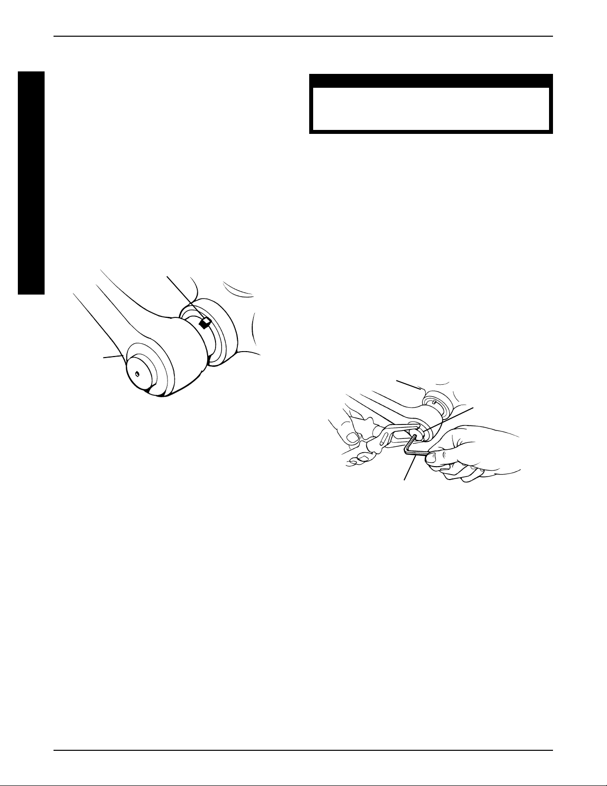
OPERATIONPROCEDURE 12
Bearing Play Adjustment (FIGURE 6)
NOTE: Refer to the SAFETY INSPECTION CHECKLIST
to determine how often bearing play adjustment is necessary.
O
NOTE: This adjustment is required only if there is some
play in the hand crank in a SIDE TO SIDE motion.
P
E
NOTE: There will be some play in a forward/rearward
R
motion.
A
1. Slightly tighten self-locking nut on the left side (sitting
T
I
in the handcycle) of the hand crank. DO NOT overtighten.
O
NOTE: Overtightening the self-locking nut will cause the
N
gears to engage improperly after shifting.
Self-Locking Nut
Adjusting Gear Shift Push Button (FIGURE 7)
WARNING
Incorrect adjustment of gear shift push button
may reult in a failure of the coaster brake, possibly causing injury and or damage.
1. Loosen, but do not remove the allen set screw in
the middle of the gear shift push button.
2. Turn in the gear shift push button approximately two
(2) revolutions.
3. Push the gear shift push button IN.
4. Move the hand crank slightly until the switch position engages audibly.
5. Turn the gear shift push button until it is flush with
the hand crank.
NOTE: Make sure there is some play underneath the
button.
6. Securely tighten the allen set screw in the middle
of the gear shift push button.
Hand
Crank
FIGURE 6 - MOUNT AIN DRIVE OPTION -
BEARING PLAY ADJUSTMENT
Hand Crank
Gear Shift
Push Button
Allen Wrench
FIGURE 7 - MOUNT AIN DRIVE OPTION -
ADJUSTING GEAR SHIFT PUSH BUTTON
32
Page 33

PROCEDURE 13OPTIONS
This Procedure includes the following:
Water Bottle Installation
Tow Bar Installation
Safety Light Installation
Computer Installation
Seat Positioning Strap Installation
Horizontal Handles
Tri-Pin Spinning Quad Handles
Gloves
Safety Flag
Safety Helmet
WARNING
After ANY adjustments, repair or service and BEFORE use, make sure all attaching hardware is tightened securely - otherwise injury or damage may
result.
WATER BOTTLE INSTALLATION
(FIGURE 1)
Operating the Safety Light
1. Press GREY button for ON/OFF.
2. Remove lens cover and slide Black switch back and
forth for pulse or constant mode.
Mounting the Safety Light
1. Open clip on back of safety light.
2. Place clip over back upholstery fastening flap and
release.
COMPUTER INSTALLATION
(FIGURE 1)
1. Install metal plug onto spoke of front wheel approximately 2-inches from wheel rim.
2. Align metal plug with fork assembly.
3. Secure sensor to fork using hardware provided.
NOTE: Slot in sensor MUST align with metal plug for mileage etc. to be registered on the computer.
4. Remove one (1) of the chain guard screws and attach the computer mounting bracket.
5. Snap computer into mounting bracket.
O
P
T
I
O
N
S
1. Secure the black water bottle mounting tube to the
seat frame using the hardware provided.
NOTE: Make sure that the water bottle mounting bracket
mounting holes are facing downward.
2. Attach the water bottle mounting bracket to the black
mounting tube using the hardware provided.
3. Push water bottle into mounting bracket until secure.
TOW BAR INSTALLATION (FIGURE 1)
1. Attach the tow bar mounting brackets to the rear chair
frame of the Excelerator using the hardware provided.
NOTE: Make sure that the mounting hardware is centered on the rear chair frame.
2. Insert tow bar into mounting bracket and secure with
hardware provided.
REAR SAFETY LIGHT (FIGURE 1)
WARNING
Operation of the Excelerator is subject to all traffic rules and regulations. (This may include the
use of a safety light and reflectors for dusk/night
riding.)
SEAT POSITIONING STRAP
INSTALLATION (FIGURE 1)
1. Secure seat positioning strap to back canes using
hardware provided.
HORIZONTAL HANDLES (FIGURE 1)
1. Remove existing handles and replace as shown in
FIGURE 1.
TRI-PIN QUAD HANDLES (FIGURE 1)
1. Remove existing handles and replace.
2. Loosen socket screws and adjust.
GLOVES (FIGURE 1)
1. Wrap palm loop around horizontal handle (using top
slot only) and secure by attaching velcro strips to-
gether.
2. Run velcro strip (back of hand) through bottom slot
on palm and over back of hand until tight. Secure by
attaching velcro strips together.
3. Reattach glove strips to back of glove.
Batteries
1. Remove the lens cover.
2. Insert the AAA batteries with correct polarity (+ or -).
3. Reinstall lens cover.
SAFETY FLAG INSTALLATION
(FIGURE 1)
1. Mount safety flag in holder secured to back tube on
bike frame.
33
Page 34

OPTIONSPROCEDURE 13
SAFETY HELMET (FIGURE 1)
1. Secure helmet using the chin strap.
2. Ensure proper fit.
LATERAL SUPPORT (FIGURE 1)
O
1. Position lateral support on frame as shown.
P
2. Secure with button screws.
T
I
O
N
S
Safety
Light
3. Three (3) different brackets included for different
widths.
4. Change bracket by removing the existing button
screws and attach the new bracket with the existing button screws.
Helmet
Lateral
Supports w/
Three Brackets
Computer
Seat Positioning
Strap
Water Bottle
Tow Bar
Flag
Tri-Pin Quad
Handles
Step 1
Step 3Step 2
Horizontal
Handles and
Gloves
FIGURE 1 - INSTALLATION OF OPTIONS
34
Page 35

WARRANTY
LIMITED WARRANTY
PLEASE NOTE: THE WARRANTY BELOW HAS BEEN DRAFTED TO COMPLY WITH FEDERAL LAW APPLICABLE TO
PRODUCTS MANUFACTURED AFTER JULY 4, 1975.
This warranty is extended only to the original purchaser/user of our products.
This warranty gives you specific legal rights and you may also have other legal rights which vary from
state to state.
Invacare warrants the frame to be free from defects in materials and workmanship for a period of three
(3) years from date of purchase; distributed parts and components including compensators, forks,
upholstery and miscellaneous bicycle components are warranted for a period of one (1) year from the
date of purchase; except all tires, tubes, push handles grips, foam parts, plastic coated parts, bushings,
bearings and cables which are not warranted. The Mountain Drive Option is not warranted. If within
such warranty period any such product shall be proven to be defective, such product shall be repaired
or replaced, at Invacare's option. This warranty does not include any labor or shipping charges incurred
in replacement part installation or repair of any such product. Invacare's sole obligation and your
exclusive remedy under this warranty shall be limited to such repair and/or replacement.
For warranty service, please contact the dealer from whom you purchased your Invacare product. In
the event you do not receive satisfactory warranty service, please write directly to Invacare at the
address below. Provide dealer’s name, address, date of purchase, indicate nature of the defect and, if
the product is serialized, indicate the serial number. Do not return products to our factory without our
prior consent.
LIMITATIONS AND EXCLUSIONS: THE FOREGOING WARRANTY SHALL NOT APPLY TO SERIAL NUMBERED
PRODUCTS IF THE SERIAL NUMBER HAS BEEN REMOVED OR DEFACED, PRODUCTS SUBJECTED TO NEGLIGENCE, ACCIDENT, IMPROPER OPERATION, MAINTENANCE OR STORAGE, COMMERCIAL OR INSTITUTIONAL USE, PRODUCTS MODIFIED WITHOUT INVACARE'S EXPRESS WRITTEN CONSENT (INCLUDING, BUT
NOT LIMITED TO, MODIFICATION THROUGH THE USE OF UNAUTHORIZED PARTS OR ATTACHMENTS; PRODUCTS DAMAGED BY REASON OF REPAIRS MADE TO ANY COMPONENT WITHOUT THE SPECIFIC CONSENT
OF INVACARE, OR TO A PRODUCT DAMAGED BY CIRCUMSTANCES BEYOND INVACARE'S CONTROL,
AND SUCH EVALUATION WILL BE SOLELY DETERMINED BY INVACARE. THE WARRANTY SHALL NOT APPLY
TO PROBLEMS ARISING FROM NORMAL WEAR OR FAILURE TO ADHERE TO THE THESE INSTRUCTIONS.
W
A
R
R
A
N
T
Y
THE FOREGOING WARRANTY IS EXCLUSIVE AND IN LIEU OF ALL OTHER EXPRESS WARRANTIES. IMPLIED
WARRANTIES, IF ANY, INCLUDING THE IMPLIED WARRANTIES OF MERCHANTABILITY AND FITNESS FOR A
PARTICULAR PURPOSE, SHALL NOT EXTEND BEYOND THE DURATION OF THE EXPRESS WARRANTY PROVIDED HEREIN AND THE REMEDY FOR VIOLATIONS OF ANY IMPLIED WARRANTY SHALL BE LIMITED TO
REPAIR OR REPLACEMENT OF THE DEFECTIVE PRODUCT PURSUANT TO THE TERMS CONTAINED HEREIN.
INVACARE SHALL NOT BE LIABLE FOR ANY CONSEQUENTIAL OR INCIDENTAL DAMAGES WHATSOEVER.
THIS WARRANTY SHALL BE EXTENDED TO COMPLY WITH STATE/PROVINCIAL LAWS AND REQUIREMENTS.
35
Page 36

Invacare Corporation www.invacare.com
USA Invacare Top End
One Invacare Way Sports and Recreation Products Invacare and "Yes, you can" are trademarks of Invacare
Elyria, Ohio USA 4501 63rd Circle North Corporation.
44036-2125 Pinellas Park, FL 34665 © 2000 Invacare Corporation
800-333-6900 800-532-8677 Form No. 95-124 Part No. 1056188 Rev B (1) 4/00
 Loading...