

Page 1
DEALER: This manual MUST be given to the user of the product.
USER: BEFORE using this product, read this manual and save for future reference.
For more information regarding Invacare products, parts and services; please visit www.invacare.co m
Invacare® Top End® Recreation Handcycles
XLT XLT Jr. XLT PRO
Excelerator™ Li’l Excelerator
EN User Manual
Page 2

© 2012 Invacare Corporation. All rights reserved. Republication, duplication or modification in whole or in part is prohibited without
prior written permission from Invacare. Trademarks are identified by ™ and ®. All trademarks are owned by or licensed to Invacare
Corporation or its subsidiaries unless otherwise noted.
Shimano and Nexus are registered trademarks of Shimano, Inc.
Phillips is a registered trademark of the Phillips Screw Company
Teflon is a registered trademark of E.I. Du Pont De Nemours and Company.
WD-40 and 3-IN-ONE are registered trademarks of WD-40 Company.
Invacare®
Top End® Recreation Handcycles 2 Part No 1171891
Page 3

CONTENTS
User Manual
DEALER: This manual MUST be given to the user of the product.
USER:
BEFORE using this product, read this manual and save for future reference.
1 GENERAL 6
Symbols.....................................................................................................................................................................................................................................................6
Dealer/Technician Information............................................................................................................................................................................................................6
Warranty Information...........................................................................................................................................................................................................................7
2OVERVIEW 8
Label Locations - XLT...........................................................................................................................................................................................................................8
Label Locations - XLT Jr.......................................................................................................................................................................................................................8
Label Locations - XLT PRO.................................................................................................................................................................................................................9
Label Locations - Excelerator..............................................................................................................................................................................................................9
Label Locations - L’il Excelerator .....................................................................................................................................................................................................10
Typical Product Parameters...............................................................................................................................................................................................................11
Component Identification...................................................................................................................................................................................................................16
Tire Pressure Conversion..................................................................................................................................................................................................................18
3SAFETY 19
General Guidelines...............................................................................................................................................................................................................................19
Proper Fit ...............................................................................................................................................................................................................................................20
Operating Information ........................................................................................................................................................................................................................21
Transferring Into/Out of the Handcycle .........................................................................................................................................................................................25
4 SAFETY INSPECTION/TROUBLESHOOTING 27
Safety Inspection Checklist.................................................................................................................................................................................................................27
Troubleshooting ...................................................................................................................................................................................................................................28
Suggested Maintenance Procedures.................................................................................................................................................................................................29
5 INITIAL SETUP 31
6OPERATION 33
Part No 1171891
3 Invacare® Top End® Recreation Handcycles
Page 4

CONTENTS
Braking ....................................................................................................................................................................................................................................................37
Using Parking Brake .............................................................................................................................................................................................................................38
Shifting Gears.........................................................................................................................................................................................................................................39
Backing-Up .............................................................................................................................................................................................................................................42
Maneuvering in Tight Areas ...............................................................................................................................................................................................................42
7 RIDING POSITION 43
Using Footrest Strap............................................................................................................................................................................................................................43
Adjusting the Footrest ........................................................................................................................................................................................................................43
Adjusting Hand Crank Height............................................................................................................................................................................................................45
Adjusting the Seat.................................................................................................................................................................................................................................46
Adjusting Back Angle ...........................................................................................................................................................................................................................48
Adjusting Back Height .........................................................................................................................................................................................................................49
8 WHEELS 50
Installing/Adjusting the Rear Wheel and Quick-Release Axles..................................................................................................................................................50
Determining Toe In/Toe Out............................................................................................................................................................................................................51
Adjusting Toe In/Toe Out..................................................................................................................................................................................................................52
Replacing Camber Inserts...................................................................................................................................................................................................................53
Replacing Tire Tube and Tuning/Replacement of Spokes...........................................................................................................................................................53
9 SERVICE PROCEDURES 54
Installing Hand Crank Handles ..........................................................................................................................................................................................................54
Installing Ovalized Aluminum Handles.............................................................................................................................................................................................55
Replacing Fork/Crank Assembly .......................................................................................................................................................................................................56
Replacing the Crank Arms .................................................................................................................................................................................................................61
Installing/Removing/Adjusting the Road Crown Compensator.................................................................................................................................................63
Tension Spring Installation .................................................................................................................................................................................................................65
Installing Seven Speed Shifter Cable.................................................................................................................................................................................................66
Adjusting/Replacing Seven Speed Shifter.........................................................................................................................................................................................67
Installing/Adjusting Seven Speed Hub Chain..................................................................................................................................................................................67
Installing/Adjusting Twenty-Seven Speed Cassette Chain...........................................................................................................................................................70
Replacing the Chain Guard Cover ...................................................................................................................................................................................................71
Invacare® Top End® Recreation Handcycles
4 Part No 1171891
Page 5

CONTENTS
Replacing the Sprocket Guard..........................................................................................................................................................................................................72
Removing/Installing the Front Wheel..............................................................................................................................................................................................74
Replacing/Adjusting the Parking Brake............................................................................................................................................................................................76
Replacing the Footrest/Footplates...................................................................................................................................................................................................77
Replacing Footrest Strap....................................................................................................................................................................................................................78
Replacing the Leg Guard ....................................................................................................................................................................................................................79
Replacing Seat ....................................................................................................................................................................................................................................... 80
Replacing Seat Upholstery .................................................................................................................................................................................................................81
Replacing Back Upholstery ................................................................................................................................................................................................................82
Replacing the Seat Positioning Strap................................................................................................................................................................................................83
10 OPTIONS 84
Installing Safety Lights..........................................................................................................................................................................................................................84
Installing the Water Bottle ................................................................................................................................................................................................................85
Using Safety Helmet ............................................................................................................................................................................................................................ 85
Installing/Using the Tow Bar..............................................................................................................................................................................................................86
Installing the Computer......................................................................................................................................................................................................................87
Assembling/Adjusting/Using the Handcycle Rack......................................................................................................................................................................... 88
Using the Alignment Gauge...............................................................................................................................................................................................................90
Installing Gloves....................................................................................................................................................................................................................................91
Additional Options ..............................................................................................................................................................................................................................92
Part No 1171891
5 Invacare® Top End® Recreation Handcycles
Page 6

1 GENERAL
1 General
1.1 Symbols
Warnings
Signal words are used in this manual and apply to hazards or unsafe practices which could result in personal injury or property damage.
See the information below for definitions of the signal words.
DANGER
Danger indicates an imminently hazardous situation which, if not avoided, will result in death or serious injury.
WARNING
Warning indicates a potentially hazardous situation which, if not avoided, could result in death or serious injury.
CAUTION
Caution indicates a potentially hazardous situation which, if not avoided, may result in property damage or minor injury or
both.
!
1.2 Dealer/Technician Information
The term “qualified technician” in this manual refers to an Invacare qualified technician or a Shimano® certified bicycle repair technician.
.
Invacare® Top End® Recreation Handcycles
IMPORTANT
Indicates a hazardous situation that could result in damage to property if it is not avoided.
Gives useful tips, recommendations and information for efficient, trouble-free use.
6 Part No 1171891
Page 7

1 GENERAL
1.3 Warranty Information
PLEASE NOTE: THE WARRANTY BELOW HAS BEEN DRAFTED TO COMPLY WITH FEDERAL LAW APPLICABLE TO PRODUCTS
MANUFACTURED AFTER JULY 4, 1975.
This warranty is extended only to the original purchaser who purchases this product when new and unused from Invacare or a dealer. This
warranty is not extended to any other person or entity and is not transferable or assignable to any subsequent purchaser or owner. Coverage
under this warranty will end upon any such subsequent sale or other transfer of title to any other person.
This warranty gives you specific legal rights and you may also have other legal rights which vary from state to state.
Invacare warrants the frames when purchased new and unused to be free from defects in materials and workmanship for a period of three (3)
years from the date of purchase from Invacare or a dealer, with a copy of the seller’s invoice required for coverage under this warranty.
Invacare warrants the upholstered materials (seat and back) and remaining components of this product when purchased new and unused to be
free from defects in materials and workmanship for a period of thirteen (13) months from date of purchase from Invacare or a dealer, with a
copy of the seller’s invoice required for coverage under this warranty. If within such warranty periods any such product shall be proven to be
defective, such product shall be repaired or replaced, at Invacare’s option. This warranty does not include any labor or shipping charges
incurred in replacement part installation or repair of any such product. Invacare’s sole obligation and your exclusive remedy under this
warranty shall be limited to such repair and/or replacement.
For warranty service, please contact the dealer from whom you purchased your Invacare product. In the event you do not receive satisfactory
warranty service, please write directly to Invacare at the address at the bottom of this page. Provide dealer’s name, address, the product
model number, date of purchase, indicate nature of the defect and, if the product is serialized, indicate the serial number. Do not return
products to our factory without our prior consent.
LIMITATIONS AND EXCLUSIONS: THE FOREGOING WARRANTY SHALL NOT APPLY TO SERIAL NUMBERED PRODUCTS IF THE
SERIAL NUMBER HAS BEEN REMOVED OR DEFACED, PRODUCTS SUBJECTED TO NEGLIGENCE, ACCIDENT, IMPROPER
OERPATION, MAINTENANCE OR STORAGE, PRODUCTS MODEIFIED WITHOUT INVACARE’S EXPRESS WRITTEN CONSENT
INCLUDING, BUT NOT LIMITED TO, MODIFICATION THROUGH THE USE OF UNAUTHORIZED PARTS OR ATTACHMENTS;
PRODUCTS DAMAGE BY REASON OF REPAIRS MADE TO ANY COMPONENT WITHOUT THE SPECIFIC CONSENT OF INVACARE,
OR TO A PRODUCT DAMAGED BY CIRCUMSTANCES BEYOND INVACARE’S CONTROL, AND SUCH EVALUATION WILL BE
SOLELY DETERMINED BY INVACARE. THE WARRANTY SHALL NOT APPLY TO NORMAL WEAR AND TEAR OR FAILURE TO
ADJERE TO THE PRODUCT INSTRUCTIONS.
THE FOREGOING EXPRESS WARRANTY IS EXCLUSIVE AND IN LIEU OF ANY OTHER WARRANTIES WHATSOEVER, WHETHER
EXPRESS OR IMPLIED, INCLUDING THE IMPLIED WARRANTIES OF MERCHANTABILITY AND FITNESS FOR A PARTICULAR
PURPOSE, AND THE SOLE REMEDY FOR VIOLATIONS OF ANY WARRANTY WHATSOEVER, SHALL BE LIMITED TO REPAIR OR
REPLACEMENT OF THE DEFECTIVE PRODUCT PURSUANT TO THE TERMS CONTAINED HEREIN. THE APPLICATION OF ANY
IMPLIED WARRANTY WHATSOEVER SHALL NOT EXTEND BEYOND THE DURATION OF THE EXPRESS WARRANTY PROVIDED
HEREIN. INVACARE SHALL NOT BE LIABLE FOR ANY CONSEQUENTIAL OR INCIDENTAL DAMAGES WHATSOEVER.
SOME STATES DO NOT ALLOW THE EXCLUSION OR LIMITATION OF INCIDENTAL OR CONSEQUENTIAL DAMAGE, OR
LIMITATION OF HOW LONG AN IMPLIED WARRANTY LASTS, SO THE ABOVE EXLUSION AND LIMITATION MAY NOT BE
APPLICABLE.
THIS WARRANTY SHALL BE EXTENDED TO COMPLY WITH STATE/PROVINCIAL LAWS AND REQUIREMENTS.
Part No 1171891
7 Invacare® Top End® Recreation Handcycles
Page 8
2 OVERVIEW
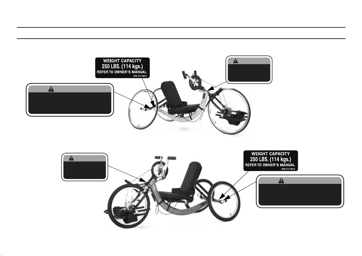
Backrest MUST be adjusted properly. Refer to
owner’s manual. Otherwise, user’s elbows may
contact rear wheels during use. Operate with
caution.
P/N 1154264 Rev A
WARNING
ALWAYS keep fingers and
hands away from the chain
while using the handcycle,
otherwise injury may occur.
P/N 1154265 Rev A
WARNING
2 Overview
2.1 Label Locations - XLT
2.2 Label Locations - XLT Jr.
Invacare® Top End® Recreation Handcycles
8 Part No 1171891
Page 9
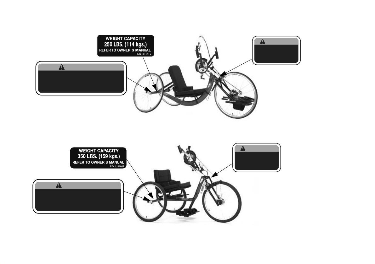
2.3 Label Locations - XLT PRO
Backrest MUST be adjusted properly. Refer to
owner’s manual. Otherwise, user’s elbows may
contact rear wheels during use. Operate with
caution.
P/N 1154264 Rev A
WARNING
ALWAYS keep fingers and
hands away from the chain
while using the handcycle,
otherwise injury may occur.
P/N 1154265 Rev A
WARNING
2.4 Label Locations - Excelerator
2 OVERVIEW
Part No 1171891
9 Invacare® Top End® Recreation Handcycles
Page 10
2 OVERVIEW
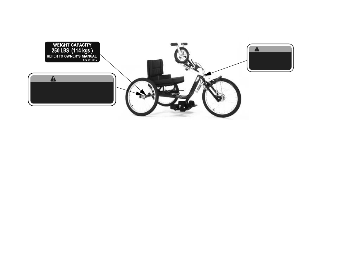
Backrest MUST be adjusted properly. Refer to
owner’s manual. Otherwise, user’s elbows may
contact rear wheels during use. Operate with
caution.
P/N 1154264 Rev A
WARNING
ALWAYS keep fingers and
hands away from the chain
while using the handcycle,
otherwise injury may occur.
P/N 1154265 Rev A
WARNING
2.5 Label Locations - L’il Excelerator
Invacare® Top End® Recreation Handcycles
10 Part No 1171891
Page 11

2.6 Typical Product Parameters
XLT
Seat Width: 15 or 17 inches (38.1 to 43.2 cm)
Seat Depth: 15 inches (38.1 cm)
Seat-to-Floor (approx.): 12, 13, or 14 inches (30.48, 33.02, or 35.56 cm) with 2 inch (5.1 cm) cushion
Back Style: Adjustable Back Angle 90° - 110°
Back Height Fixed/Adjustable Angle: 20 inches (Narrow, Tall) (50.8 cm)
Footrest: Adjustable Fore and Aft
Side - Wheel Clearance: 2 inches - * 2½ inches (5.08 - 6.35 cm)
Rear Axle: Quick-Release
Rear Wheel Camber: 15° - Standard
Wheels/Tires: 26-inch Spoke High Performance (66.04 cm)
Brakes: Internal reversing drum brakes and parking brake
Handles: Ergonomic
Crankset: Alloy Crankset
Hub: FRONT - Shimano Nexus® 7 Speed Hub
REAR - Precision Black Anodized w/½-inch Quick Release Stainless Axles
Spokes: 14 Gauge Stainless
Shift Levers: Shimano indexed twist grip with gear display
Gears: 7 Speed
Seat and Back Cushion: Standard
Upholstery: Nylon
Weight: 35 lbs (16 kg)
Shipping Weight: 65 lbs (30 kg)
Weight Limitation: 250 lbs (114 kg)
Options: Standard Options: Safety Flag, Chainguard, Trunk Restraint and cushion
Other Options: Mirror, Backpack Hydration System, Computer, Tow Bar, Safety Lights, Helmet, Quad Gloves, Mountain
Drive, Bike Rack, Water Bottle and Cage, Tri-pin Quad Handles, Leg Guard Attachment, Alignment Gauge, Crutch Holder,
Click Straps, Tool and Tire Repair Kit, Quad Twist Shift Adaptation
2 OVERVIEW
Part No 1171891
11 Invacare® Top End® Recreation Handcycles
Page 12

2 OVERVIEW
XLT Jr.
Seat Width: 14 inches (35.56 cm)
Seat Depth: 15 inches (38.1 cm)
Seat-to-Floor (approx.): 12, 13, or 14 inches (30.48, 33.02, or 35.56 cm) with 2 inch (5.1 cm) cushion
Back Style: Adjustable Back Angle 90° - 110°
Back Height Fixed/Adjustable Angle: 11-14 inches (Wide) (27.44 - 35.56 cm)
Footrest: Adjustable Fore and Aft
Side - Wheel Clearance: 2 inches - 2½ inches (5.08 - 6.35 cm)
Rear Axle: Quick-Release
Rear Wheel Camber: 15° - Standard
Wheels/Tires: 20-inch Cruiser (50.8 cm)
Brakes: Internal reversing drum brakes and parking brake
Handles: Ergonomic, Vertical foam covered or Horizontal foam covered
Crankset: Alloy Crankset
Hub: FRONT - Shimano Nexus 7 Speed Hub
Spokes: 14 Gauge Stainless
Shift Levers: Shimano indexed twist grip with gear display
Gears: 7 Speed
Seat and Back Cushion: Foam Insert Standard
Upholstery: Nylon
Weight: 30-35 lbs (14 - 16 kg)
Shipping Weight: 65 lbs (30 kg)
Weight Limitation: 250 lbs (114 kg)
Options: Standard Options: Safety Flag, Chainguard, Trunk Restraint and cushion
16½ inches (Narrow, Tall) (41.9 cm)
REAR - Precision Black Anodized w/½-inch Quick Release Stainless Axles
Other Options: Mirror, Backpack Hydration System, Computer, Tow Bar, Safety Lights, Helmet, Quad Gloves, Mountain
Drive, Bike Rack, Water Bottle and Cage, Tri-pin Quad Handles, Leg Guard Attachment, Alignment Gauge, Crutch Holder,
Click Straps, Tool and Tire Repair Kit, Quad Twist Shift Adaptation
Invacare® Top End® Recreation Handcycles
12 Part No 1171891
Page 13

2 OVERVIEW
XLT PRO
Seat Width: 15 or 17 inches (38.1 to 43.2 cm)
Seat Depth: 15 inches (38.1 cm)
Seat-to-Floor (approx.): 12, 13 and 14 inches (30.48, 33.02, and 35.56 cm) with 2” (5.1 cm) cushion
Back Style: Adjustable Back Angle 90° - 110°
Back Height Fixed/Adjustable Angle: 18½ inches (Narrow, Tall) (50.8 cm)
Footrest: Adjustable Fore and Aft
Side - Wheel Clearance: 2 inches - * 2½ inches (5.08 - 6.35 cm)
Rear Axle: Quick-Release
Rear Wheel Camber: 15° - Standard (38.1 cm)
Wheels/Tires: 26-inch Spoke High Performance (66.04 cm)
Brakes: Rapid fire hands-on brake mounted on right pedal. Parking brake on L frame
Handles: Ergonomic, Vertical, Ovalized Aluminum mounted on Top End V crankset
Crankset: Top End V Crankset
Hub: FRONT - Shimano/Top End Components w/ 27 Speed External Cassette
Spokes: 14 Gauge Stainless
Shift Levers: Rapid fire hands-on shifter mounted on right handpedal for lower derailler, Manual shifter for upper derailler/chainrings.
Gears: 27 Speed
Seat and Back Cushion: Foam Insert Standard
Upholstery: Nylon
Weight: 30 lbs (14 kg)
Shipping Weight: 65 lbs (30 kg)
Weight Limitation: 250 lbs (114 kg)
Options: Standard Options: Safety Flag, Chainguard, Trunk Restraint and cushion
REAR - Precision Black Anodized w/½-inch Quick Release Stainless
Other Options: Computer, Tow Bar, Safety Lights, Helmet, Bike Rack, Water Bottle and Cage, Leg Guard
Attachment, Alignment Gauge, Backpack Hydration System, Crutch Holder, Click Straps, Safety Mirrors
Part No 1171891
13 Invacare® Top End® Recreation Handcycles
Page 14

2 OVERVIEW
Excelerator
Seat Width: 17 or 20 inches (43.2 cm or 50.8 cm)
Seat Depth: 15 inches (38.1 cm)
Seat-to-Floor (approx.): Fixed 20/18 inches (50.8 cm/45.7 cm)
Back Style: Rigid
Back Height (Adjustable): 11-14 inches (27.9 - 35.6 cm) with a 90° angle
Footrest: Adjustable Height/Angle
Side - Wheel Clearance: 2 inches - * 2½ inches (5.1 - 6.4 cm)
Rear Axle: Quick-Release
Rear Wheel Camber: 9° - Standard
Wheels/Tires: 24-inch Spoke Cruiser Tires (61 cm)
Brakes: Hand Crank (internal), Parking Brake
Handpedals: Ergonomic
Hub: FRONT - Shimano Nexus® 7 Speed Hub with Internal Drum Brake
REAR - Precision Black Anodized w/1/2-inch Quick Release Stainless Axles
Spokes: 14 Gauge Stainless
Shift Levers: Shimano Indexed Twist Grip
Gears: 7 Speed
Seat and Back Cushion: Foam Insert
Upholstery: Nylon Foldover
Weight: 50 lbs (23 kg)
Shipping Weight: 80 lbs (26 kg)
Weight Limitation: 350 lbs (159 kg)
Options: Standard Options: Safety Flag, Chainguard, Trunk Restraint and cushion
Other Options: Computer, Tow Bar, Safety Light, Helmet, Gloves, Mountain Drive, Bike Rack, Water Bottle and Cage,
Tri-pin Quad Handles, V Crankset, Auto-style Restraint, Mirror, Crutch Holder and Strap, Quad Twist Shifter Adaptation
Invacare® Top End® Recreation Handcycles
14 Part No 1171891
Page 15

L’il Excelerator
Seat Width: 14 inches (35.6 cm)
Seat Depth: 14 inches (35.6 cm)
Seat-to-Floor (approx.): Fixed 17.5/15.5 inches (44.5 cm/39.4 cm)
Back Style: Rigid
Back Height (Adjustable): 11-14 inches (27.9 - 35.6 cm)
Footrest: Adjustable Height/Angle
Side - Wheel Clearance: 2 inches - * 2½ inches (5.1 - 6.4 cm)
Rear Axle: Quick-Release
Rear Wheel Camber: 9° - Standard
Wheels/Tires: 20-inch Spoke Cruiser Tires (50.8 cm)
Brakes: Hand Crank (internal), Parking Brake
Handpedals: Horizontal
Hub: FRONT - Shimano Nexus® 7 Speed Hub with Internal Drum Brake
REAR - Precision Black Anodized w/1/2-inch Quick Release Stainless Axles
Spokes: 14 Gauge Stainless
Shift Levers: Shimano Indexed Twist Grip with Gear Display
Gears: 7 Speed
Seat Cushion: Foam Insert
Upholstery: Nylon Foldover
Weight: 40 lbs (18 kg)
Shipping Weight: 70 lbs (32 kg)
Weight Limitation: 250 lbs (114 kg)
Options: Standard Options: Safety Flag, Chainguard, Trunk Restraint and cushion
Other Options: Safety Light, Helmet, Gloves, Bike Rack, Water Bottle and Cage, Auto-Style Restraint, Mirror, Quad Twist
Shifter Adaptation, Crutch Holder
2 OVERVIEW
Part No 1171891
15 Invacare® Top End® Recreation Handcycles
Page 16
2 OVERVIEW
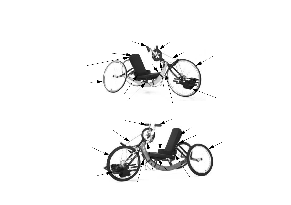
Hand Crank Assembly with
Reversing Drum Brake
Back
Rear Wheel
Seat
Chain
Footrest and Safety Straps
Hand Pedal
Parking Brake
Seat Positioning Strap
Front Wheel with Internal
Geared Hub
Safety flag not
shown.
Shifter not shown.
Chain Guard
Safety Flag Holder
Road Crown Compensator
Hand Crank Assembly with Reversing Drum Brake
Back
Rear Wheel
Seat
Chain
Footrest and Safety Straps
Shifter
Hand Pedal
Seat Positioning Strap
Front Wheel
with Internal
Geared Hub
Safety flag not
shown.
Parking brake
not shown.
Chain
Guard
Safety Flag Holder
Road Crown Compensator
2.7 Component Identification
XLT
XLT Jr.
Invacare® Top End® Recreation Handcycles
16 Part No 1171891
Page 17
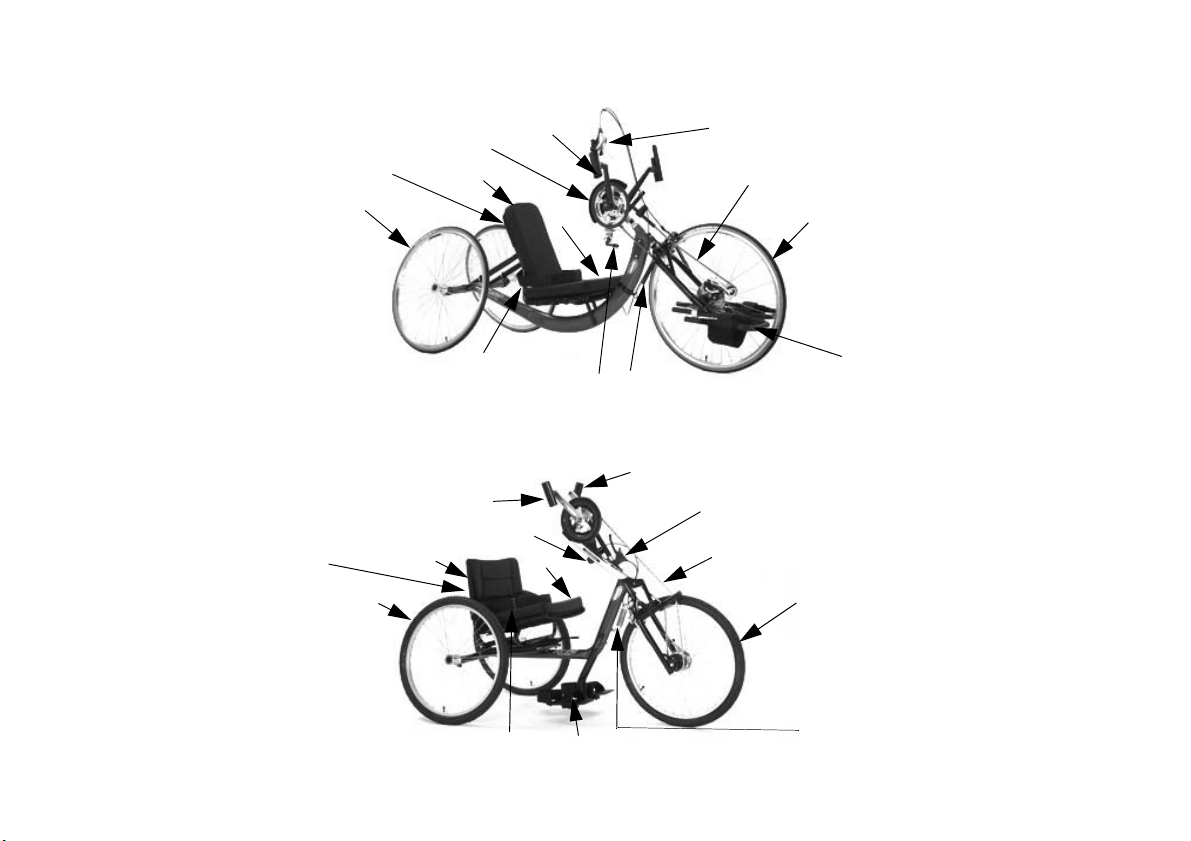
XLT PRO
Hand Crank Assembly
Back
Rear Wheel
Seat
Chain
Rapid-Fire Hand Brake/Shifter for Front Cassette
Footrest and Safety Straps
Chain Guard
Seat Positioning Strap
Upper Chain Ring Shifter
Front Wheel with External Geared Hub
Safety flag not
shown.
Safety Flag Holder
Road Crown Compensator
Front Wheel with Internal Geared Hub
Back
Hand Crank Assembly with Reversing Drum Brake
Chain
Footrest and Safety Straps
Shifter
Parking Brake
Safety flag not
shown.
Hand Pedal
Rear Wheel
Seat Positioning Strap
Seat
Safety Flag Holder
Tension Spring
Excelerator
2 OVERVIEW
Part No 1171891
17 Invacare® Top End® Recreation Handcycles
Page 18
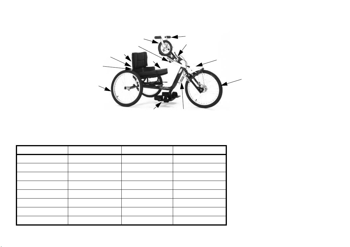
2 OVERVIEW
Rear Wheel
Back
Hand Crank Assembly with Reversing Drum Brake
Chain
Footrest and Safety Straps
Shifter
Parking Brake
Seat Positioning Strap
Seat
Hand Pedal
Front Wheel with Internal Geared Hub
Safety Flag Holder
Tension Spring
L’il Excelerator
2.8 Tire Pressure Conversion
PSI rating is printed on the side of the tire.
Conversion formula: 1 psi = 6.895 kPa (approx. 7 kPa).
PSIKILOPASCALSPSIKILOPASCALS
50 345 90 621
55 379 95 655
60 414 100 690
65 448 105 724
70 483 110 758
75 517 115 793
80 552 120 827
85 586
Invacare® Top End® Recreation Handcycles
18 Part No 1171891
Page 19

3 Safety
The safety section contains important information for the safe operation and use of this product.
3.1 General Guidelines
3 SAFETY
!
WARNING
DO NOT use this product or any available optional equipment without first completely reading and understanding these
instructions and any additional instructional material such as owner’s manuals, service manuals or instruction sheets supplied
with this product or optional equipment. If you are unable to understand the warnings, cautions or instructions, contact a
healthcare professional, dealer or technical personnel before attempting to use this equipment - otherwise, injury or damage
may occur.
A qualified technician MUST perform the initial set up of this wheelchair. Also, a qualified technician must perform all
procedures specifically indicated in the manual.
ACCESSORIES WARNINGS
Invacare products are specifically designed and manufactured for use in conjunction with Invacare accessories. Accessories
designed by other manufacturers have not been tested by Invacare and are not recommended for use with Invacare
products.
NOTICE
THE INFORMATION CONTAINED IN THIS DOCUMENT IS SUBJECT TO CHANGE WITHOUT NOTICE.
Check all parts for shipping damage and test before using. In case of damage, DO NOT use. Contact Invacare/Carrier for
further instruction.
Part No 1171891
19 Invacare® Top End® Recreation Handcycles
Page 20

3 SAFETY
3.2 Proper Fit
The handcycle MUST be adjusted to fit the rider. Check the seat position, back angle, quick-release axles, footrest fore/aft position, hand crank height for
proper fit and smooth operation of your handcycle.
• The rider MUST be able to see over the hand crank.
• The rider MUST have a slightly bent elbow when the hand pedals are toward the front of the handcycle (farthest from the rider’s face).
• The rider’s knees MUST not obstruct hand crank operation.
• XLT Series - the rider MUST have a slight bend at the knee when feet are in the footrests. Feet should be flat against footrest hoop.
• XLT Series requires a 18” turning radius. If leg touches tire during turn and the user cannot sense this, a leg guard attachment is recommended.
• Excelerator Series - the rider MUST have a 90° bend at the knee when feet are in the footrests.
• Excelerator Series - Footrests MUST be adjusted to allow a minimum of a 2-inch clearance between the bottom of the footrest and the ground.
Invacare® Top End® Recreation Handcycles
20 Part No 1171891
Page 21

3.3 Operating Information
WARNING - RISK OF INJURY OR DAMAGE
HANDCYCLE USER
As a manufacturer of handcycles, Invacare endeavors to supply a handcycle to meet many needs of the end user. However,
final selection of a handcycle to be used by an individual rests solely with the user and his/her health care professional capable
of making such a selection
TRANSPORT
Invacare recommends that a handcycle user is NOT transported in vehicles of any kind while in a handcycle. As of this date,
the Department of Transportation has not approved any tie-down systems for transportation of a user while in a handcycle,
in a moving vehicle of any type.
SEAT POSITIONING STRAP
SERIOUS INJURY CAN OCCUR IN THE EVENT OF A FALL FROM THE PRODUCT.
ALWAYS wear your seat positioning strap. Invacare strongly recommends using the seat positioning strap as an additional
safeguard for the handcycle user. The seat positioning strap is a positioning belt only. It is not designed for use as a safety
device withstanding high stress loads such as auto or aircraft safety belts. If signs of wear appear, the belt MUST be replaced
IMMEDIATELY
BRAKES
(XLT PRO Model Only) If the brake cable show signs of wear or if it has become tangled because of improper
transportation techniques, the cable MUST be replaced or the brake may fail. Should the primary brake fail, the parking brake
can be used a backup emergency brake.
(ALL HANDCYCLE Models) Before riding your handcycle, ALWAYS check the function of the brakes. Be sure that the
brakes and all other features of your handcycle are operating properly.
3 SAFETY
Part No 1171891
21 Invacare® Top End® Recreation Handcycles
Page 22

3 SAFETY
WARNING - RISK OF INJURY OR DAMAGE
Care, consideration and practice MUST be taken and observed in the following safety points. Otherwise, injury or damage
may occur.
Safe use requires the close attention of the user as well as the assistant. This user manual points out the most common procedures and
techniques involved in the safe operation and maintenance of the handcycle. It is important to practice and master these safe techniques
until you are comfortable in maneurvering the handcycle.
A helmet MUST ALWAYS be worn when operating the handcycle.
Shoes MUST ALWAYS be worn and feet MUST be secured to the footrests with the straps when operating the handcycle.
Before riding your handcycle, ALWAYS check the function of the brakes. Be sure that the brakes and all other features of your handcycle
are operating properly.
ALWAYS keep fingers and hands away from the chain while using the handcycle.
The Backrest MUST be adjusted properly. Otherwise, user’s elbows may contact rear wheels during use. Operate with caution.
DO NOT let children play near the handcrank or the chain. Otherwise, injury or damage may occur.
The user is responsible for normal upkeep and maintaining the handcycle in proper operating condition.
The manufacturer is not responsible for failure, damage or injury caused by improper operation or maintenance by the end-user.
To determine and establish your particular safety limits, practice transferring activities in the presence of a qualified health care professional
before attempting active use of the handcycle.
Care MUST be taken when operating on roads, streets or highways. Use safety flag when operating on roads, streets or highways. The safety
flag is an option for these handcycle models.
Operation of the handcycle is subject to all traffic rules and regulations. (This may include the use of a safety lights and reflectors for
dusk/night riding.) Give pedestrians the right of way.
Slow down when turning or cornering, otherwise injury or damage may occur.
Invacare® Top End® Recreation Handcycles
22 Part No 1171891
Page 23

3 SAFETY
WARNING - RISK OF INJURY OR DAMAGE
Use proper hand signals when turning.
Slow down at all street intersections and observe to the right, to the left and back to right again before proceeding.
DO NOT attempt to move up or down an incline with an ice or oil film. Avoid all surface hazards.
DO NOT attempt to ride over curbs or obstacles or speed bumps. Doing so may cause your handcycle to "bottom out"
and/or turn over and cause bodily harm or damage to the handcycle.
DO NOT attempt to lift the handcycle by any removable (detachable) parts. Lifting by means of any removable (detachable)
parts of an handcycle may result in injury to the user or damage to the handcycle.
DO NOT stand on the seat or frame of the handcycle.
DO NOT carry any riders.
DO NOT carry any items that may obstruct your view or prohibit you from operating the handcycle properly.
DO NOT attempt to adjust or clean the internal gear hub with reversing drum brake. This should only be performed by a
bicycle professional.
TIRE PRESSURE
DO NOT use your handcycle unless it has the proper tire pressure. DO NOT overinflate the tires. Failure to follow these
suggestions may cause the tire to explode and cause bodily harm.
DO NOT ride on a flat or under inflated tires. Riding on flat or underinflated tires can cause injury, as well as, damage to the
tire, tube and handcycle wheels.
Part No 1171891
23 Invacare® Top End® Recreation Handcycles
Page 24

3 SAFETY
WARNING - RISK OF INJURY OR DAMAGE
WEIGHT LIMITATION
The Invacare XLT series handcycles have a weight limitation of 250 lbs (113.4 kg).
The Invacare Excelerator handcycle has a weight limitation of 350 lbs (158.7 kg).
The Invacare L’il Excelerator handcycle has a weight limitation of 250 lbs (113.4 kg)
STABILITY AND BALANCE
For stability and proper operation of your handcycle, you MUST at all times maintain proper balance. Turning and cornering
affects the stability and balance of the handcycle and user. Your handcycle should remain upright and stable during turns and
cornering when operated correctly.
Invacare recommends using seat positioning strap for additional safety.
A NOTE TO HANDCYCLE ASSISTANTS
When learning assistance techniques for the handcycle, have an experienced assistant help you before attempting it alone.
When you are assisting with a transfer to/from the handcycle, remember to use good body mechanics. Keep your back
straight and bend your knees when lifting or positioning the handcycle for the end-user.
Also, be aware of detachable parts. These must NEVER be used for lifting supports or to move the handcycle, as they may be
inadvertently released, resulting in possible injury to the user and/or assistant.
PERCENTAGE OF WEIGHT DISTRIBUTION
Transferring in and out of the handcycle, turning and cornering will cause a change to the normal balance, the center of
gravity, and the weight distribution of the handcycle. To determine and establish your particular safety limits, practice
transferring activities in several combinations in the presence of a qualified health care professional before attempting a
transfer alone.
Proper positioning is essential for your safety.
.
Invacare® Top End® Recreation Handcycles
24 Part No 1171891
Page 25

3.4 Transferring Into/Out of the Handcycle
3 SAFETY
WARNING - RISK OF INJURY OR DAMAGE
Before attempting to transfer in or out of the handcycle, every precaution should be taken to reduce the gap distance.
Position the handcycle on level ground and as close as possible to the object you are transferring into or out of.
The object you are transferring into or out of MUST also be secured before attempting any transfer.
The parking brake of the handcycle MUST be engaged before attempting any transfer.
CAUTION
When transferring, position yourself as far forward as possible in the seat. This will prevent damage to the upholstery.
1. Position the handcycle on level ground and as close as possible along side the object to/from which you are transferring.
2. If possible, position the handcycle at a 45° angle to the object to/from which you are transferring.
3. If installed, apply the parking brake on the handcycle.
4. Position the hand pedals as far forward as possible. This will create more room to transfer.
5. Secure object that you are transferring into or out of. Apply wheel locks (if installed) if the object is a handcycle.
6. Lift and place left leg past the front frame across the seat and over the center tube.
7. Place one hand on far side of seat.
8. Shift body weight onto object while transferring.
9. To transfer out of the handcycle, reverse the procedure and use the backrest to push off.
This activity may be performed independently provided you have adequate mobility and upper body strength.
If necessary, lift the front wheel off the ground and rotate the front tire.
During independent transfer, little or no seat platform will be beneath you. Although it may be difficult to wedge the
transfer board between the handcycle seat and the handcycle seat, use a transfer board if necessary.
Part No 1171891
25 Invacare® Top End® Recreation Handcycles
Page 26
3 SAFETY
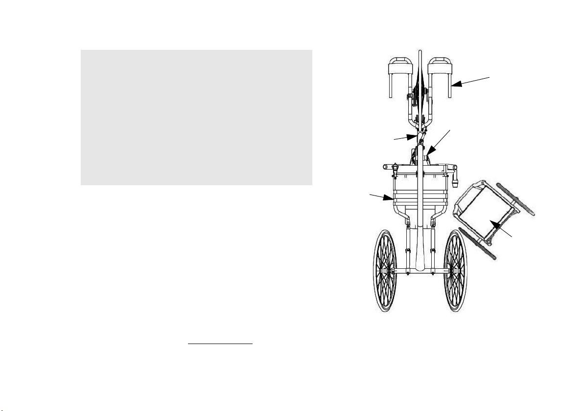
Handcycle Pedals
(rotate to the 3 o’clock position)
Footrest
Seat Frame
The steps below are specifically for transfer to/from a wheelchair and DO NOT
correspond to the steps in the procedure on the previous page. Follow a similar
procedure to transfer to/from an object other than a wheelchair. Refer to the steps
on the previous page for more information.
STEP A: Shift body weight to the edge of the wheelchair upholstery closest to the
handcycle.
STEP B: Lift and place LEFT leg across seat.
STEP C: Place LEFT hand on the left side of handcycle seat frame, NOT on crank.
STEP D: Place RIGHT hand on the wheelchair frame.
STEP E: Lift and shift weight down into handcycle seat.
STEP F: Place both legs onto handcycle footrests and secure safety straps.
STEP G: Adjust the handcycle seat. Refer to Adjusting the Seat
on page 46.
Handcycle
Wheelchair
WARNING - RISK OF INJURY OR
DAMAGE
If installed on handcycle, parking brake and wheel locks
MUST be engaged.
WHEELCHAIRS
Wheel locks are not brakes.
Engaging the wheel locks may not prevent the wheelchair
from moving on all floor surfaces including those that may
be wet or slick. ALWAYS exercise caution when
transferring into or out of the wheelchair.
Part No 1171891
26 Invacare® Top End® Recreation Handcycles
Page 27

4 Safety Inspection/Troubleshooting
4 SAFETY INSPECTION/TROUBLESHOOTING
4.1 Safety Inspection Checklist
Initial adjustments should be made to suit your personal body structure and preference. Thereafter follow these maintenance procedures:
Inspect/Adjust Initially and Weekly
Inspect for bent or broken frame.
Inspect parking brake - Adjust brake shoes to front rim. Check for worn or missing shoes. Check for wax or oil on rim.
Ensure cable anchor is attached securely to brake arm.
Ensure the brakes are working before you begin a ride. When fully applied, the handcycle should come to a complete stop.
Every six months or as necessary, take your handcycle to a qualified technician for a thorough inspection and servicing. Regular cleaning
will reveal loose or worn parts and enhance the smooth operation of your handcycle. For safe and proper operation, your handcycle
MUST be cared for just like any other vehicle. Routine maintenance will extend the life and efficiency of your handcycle.
CAUTION
Ensure axle nuts are tight. Wheel should be centered in fork. Keep wheel bearings adjusted and keep spokes tight and wheel in proper alignment.
Inspect rim and fork assembly for damage.
Ensure axle nut and wheel mounting nuts are secure.
Ensure that the rear wheels are properly secured to the frame.
Inspect wheels for excessive side movement or binding when lifted and spun.
Inspect for flat spots, wear and proper inflation.
Inspect chain/chain guard for damage, rust, tension and stretch. Adjust if necessary. Lubricate each link (3-IN-ONE® oil or a quality bike lubricant).
Check for damage or looseness.
Adjust shifter/brake cables according to shifter/brake manufacturer's instructions (included with the handcycle).
Inspect front fork. Keep tight and lubricate (All purpose grease).
Inspect footrest mounting hardware is tight and footrest secure.
Inspect footrest straps for wetness and/or damage.
Inspect seat positioning strap (if installed) for any signs of wear. Ensure buckle latches or hook and loo fastener is secure. Verify hardware that
attaches strap to frame is secure and undamaged. Replace if necessary.
As with any vehicle, the wheels/castors and tires should be checked periodically for cracks, flat spots and wear, and should be replaced.
Part No 1171891
27 Invacare® Top End® Recreation Handcycles
Page 28

4 SAFETY INSPECTION/TROUBLESHOOTING
Inspect upholstery for rips or sagging.
Clean upholstery with light detergent and water.
Check that all labels are present and legible. Replace if necessary.
Ensure that axles are free of debris.
Inspect/Adjust Periodically
Inspect upholstery for rips or sagging.
Clean upholstery with light detergent and water.
Inspect hand grips for looseness. If loose, replace.
Check that all labels are present and legible. Replace if necessary.
4.2 Troubleshooting
Veers
Right
Invacare® Top End® Recreation Handcycles
Veers
Left
X X Check road crown compensator and adjust to neutral
X X X X Check tires for correct and equal pressure
XX Check hardware and adjustment.
Sluggish Turn
or Performance
X X X X Check for loose axle nuts.
X X X Check chain for proper tension and adjustment.
Wheel
Flutter
X X Check that goose neck fittings are secure.
Squeaks
and Rattles
X X Check spokes and nipples.
Looseness
in Handcycle
Solutions
28 Part No 1171891
Page 29

4 SAFETY INSPECTION/TROUBLESHOOTING
4.3 Suggested Maintenance Procedures
WARNING - RISK OF INJURY OR DAMAGE
1. Before using your handcycle, make sure all nuts and bolts are tight. Check all parts for damage or wear and replace. Check all parts for proper
adjustment.
2. Check brakes.
After any adjustments, repair or service and before use, make sure all attaching hardware is tightened securely. Otherwise injury or
damage may result.
DO NOT overtighten hardware attaching to the frame. This could cause damage to the frame tubing.
WARNING - RISK OF INJURY OR DAMAGE
• Check cables for signs of wear or fraying and replace to avoid failure.
• Squeeze the brake lever firmly or pedal backwards and check for proper brake function.
• Adjust for pad wear if necessary.
• Check pads for wear and replace if necessary.
• Ensure rotors are free of foreign substances and oils.
3. Check parking brake cable and shifter adjustment cables for proper adjustment and operation. Refer to Adjusting/Replacing Seven Speed Shifter
on page 67 and Replacing/Adjusting the Parking Brake
Damaged brakes may not stop the handcycle. Injury or damage may occur. Always check brakes before each use of the handcycle.
on page 76.
WARNING - RISK OF INJURY OR DAMAGE
4. Clean/oil quick-release axles and or threaded once a week with a Teflon® lubricant.
5. Keep quick-release axles free of dirt and lint to ensure positive locking and proper operation.
DO NOT use WD-40®, 3-IN-ONE® oil or other penetrating lubricants on quick-release axles. Otherwise, binding and/or damage to
the handcycle can occur.
WARNING - RISK OF INJURY OR DAMAGE
DO NOT use the handcycle unless it has the proper tire pressure (p.s.i.). DO NOT overinflate the tires. Failure to follow these
suggestions may cause the tire to explode and cause bodily harm.
Part No 1171891
29 Invacare® Top End® Recreation Handcycles
Page 30

4 SAFETY INSPECTION/TROUBLESHOOTING
6. Recommended tire pressure is listed on the side wall of the tire. If tire needs replaced, contact a local bike shop for replacement.
CAUTION
7. The wheels and tires should be checked periodically for cracks and wear, and should be replaced if damaged.
8. Check chain for slack and readjust if necessary. Installing/Adjusting Twenty-Seven Speed Cassette Chain on page 70.
9. Regularly check for loose spokes in the front and rear wheels. If loose, have them aligned at your local bike shop.
10. Check road crown compensator for proper operation. Refer to Installing/Removing/Adjusting the Road Crown Compensator
11. Check upholstery for sagging, rips or tears. Refer to Replacing Seat Upholstery
12. Check alignment of front wheel. If it wobbles or takes too much effort to turn by hand, have it aligned at your local bicycle shop.
As with any vehicle, the wheels and tires should be checked periodically for cracks and wear, and should be replaced.
on page 63.
on page 81.
Invacare® Top End® Recreation Handcycles
30 Part No 1171891
Page 31

5 Initial Setup
WARNING - RISK OF INJURY OR DAMAGE
1. Install the rear wheels. Refer to Installing/Adjusting the Rear Wheel and Quick-Release Axles on page 50.
2. Adjust footrest. Refer to Adjusting the Footrest on page 43.
After any adjustments, repair or service and before use, make sure all attaching hardware is tightened securely. Otherwise injury or
damage may occur.
DO NOT operate the handcycle if the hand crank obstructs your view. If the hand crank obstructs your view, adjust the hand
crank height before using the handcycle - otherwise injury or damage may occur.
Required tools:
• Adjustable Wrench (10-12 inches)
• 5, 6, 8, 9 and 32 mm Wrenches
3
•
/16-inch Allen Wrench
• ¼-inch Allen Wrench
• ½-inch Box Wrench
• ½-inch Socket Wrench
•1/8-inch Allen Wrench
• Medium Flat Screwdriver
• Medium Phillips™ Screwdriver
5 INITIAL SETUP
3. Adjust hand crank assembly if the user is unable to see over the hand crank or if knees obstruct hand crank rotation. Refer to Adjusting Hand Crank
Height on page 45.
Part No 1171891
Excelerator Series - Foot should be flat on the footrest with the knees in a 90° angle.
XLT Series - The sole of the foot should rest against the inside edge of the footrest when the knee is slightly bent.
31 Invacare® Top End® Recreation Handcycles
Page 32

5 INITIAL SETUP
4. Perform one of the following:
• XLT PRO - Adjust chain length if the hand crank has been adjusted by adding or subtracting links. Special tools are necessary and procedure
should be performed by a qualified technician. Refer to Installing/Adjusting Twenty-Seven Speed Cassette Chain
on page 70.
• All handcycles except XLT PRO - Adjust chain tension idler. Refer to Adjusting the Chain Tensioner
5. Check brakes and parking brake function. Refer to Suggested Maintenance Procedures
6. Perform one of the following:
• All handcycles except for XLT PRO - Pedal backwards to ensure reversing drum brake works properly.
• XLT PRO - Squeeze brake handle on hand pedal to ensure the brake is working properly.
7. Adjust seat and/or back if necessary. Refer to Adjusting the Seat on page 46 and Adjusting Back Angle on page 48 as necessary.
8. Check that all hardware is tight.
9. Assemble the safety flag by sliding the top half into the plastic midsection.
10. Mount safety flag in holder secured to back tube.
If necessary, take the XLT PRO to a bike shop to adjust the chain length.
on page 69.
on page 29.
Adjust the backrest so the user has a slight bend in the elbow when extended or at the 3 o’clock position.
Invacare® Top End® Recreation Handcycles
32 Part No 1171891
Page 33

6 OPERATION
6 Operation
WARNING - RISK OF INJURY OR DAMAGE
1. Check brakes. Refer to Suggested Maintenance Procedures on page 29
2. Engage the parking brake.
3. Transfer into the handcycle.
4. Ensure that the hand crank is not obstructing your view. DO NOT operate the hand cycle if hand crank obstructs your view. If the hand crank
obstructs your view, adjust the hand crank height before using the handcycle.
5. Ensure the footrest is adjusted properly.
6. Ensure the seat is adjusted properly.
7. Secure footrest straps over top of feet.
8. Secure the seat positioning strap.
9. Release the parking brake.
After any adjustments, repair or service and before use, make sure all attaching hardware is tightened securely. Otherwise injury or
damage may occur.
Before operating the handcycle, review the General Guidelines in this manual.
Damaged brakes may not stop the handcycle. Injury or damage may occur. Always check brakes before each use of the handcycle.
XLT Series - footrest should be adjusted so that when seated with feet in the footrests, there is a slight bend at the knee.
Excelerator Series - footrest height should be adjusted so that when seated with feet in the footrests, there is a 90° bend at the knee.
XLT Series - seat should be adjusted so that when seated with feet in the footrests, there is a slight bend at the knee and a slight bend at
the elbow when the hand pedals are furthest away or at the 3 o’clock position.
Excelerator Series - When seated, the seat should be adjusted so there is a 90° bend at the knee and a slight bend at the elbow when the
hand pedals are furthest away or at the 3 o’clock position.
Part No 1171891
33 Invacare® Top End® Recreation Handcycles
Page 34

6 OPERATION
WARNING - RISK OF INJURY OR DAMAGE
10. Place at least one hand onto the hand pedals. Angle the hand pedals in at the top and out at the bottom.
11. Rotate (pedal) the hand crank forward (toward the front) to propel the handcycle forward. Rotate (pedal) the hand crank backward (toward the
rear) to apply the brake and slow down or stop.
The handcrank assembly is used for propelling and steering of the handcycle. At least one hand MUST be on the hand crank assembly at
all times. Otherwise, injury or damage may occur.
Invacare® Top End® Recreation Handcycles
34 Part No 1171891
Page 35

XLT Series
6 OPERATION
XLT and XLT Jr. ONLY
Hand Crank
Seat
Front of
Handcycle
Rear of
Handcycle
Footrest
Excelerator Series
Hand Crank
Seat
Front of
Handcycle
Rear of
Handcycle
Part No 1171891
Footrest
35 Invacare® Top End® Recreation Handcycles
Page 36

6 OPERATION
Front of
Handcycle
Rapid Fire Shifter/Brake System
Seat
Footrest
Rear of
Handcycle
XLT PRO
Hand Crank
Invacare® Top End® Recreation Handcycles
36 Part No 1171891
Page 37

6 OPERATION
Squeeze Brake
Handle
Rapid-Fire Hands-On Brake
6.1 Braking
XLT, XLT Jr., Excelerator, Li’l Excelerator Handcycles have internal gearing (7 speeds). Internal geared handcycles are equipped with reversing drum
brakes. External geared handcycles have hand brakes.
Reversing Drum Brakes
Use the brakes intermittently on your handcycle to bring it to a complete
stop. Apply by pedaling in reverse.
(XLT PRO Model Only) Hand Brakes/Hands-On Brakes
WARNING - RISK OF INJURY
1. Squeeze brake handle(s) as needed to slow or come to a complete stop.
2. Release when desired speed is achieved.
OR DAMAGE
The twenty-seven speed cassette on the XLT PRO
model uses the hand brake as the primary brake.
Reverse pedaling WILL NOT stop the bike.
In situations where caution is advised (heavy traffic,
intersections, etc.) hands should be kept in the "ready"
position to prepare for braking.
Part No 1171891
37 Invacare® Top End® Recreation Handcycles
Page 38

6 OPERATION
Excelerator Series
XLT Series
Parking
Brake
Parking
Brake
6.2 Using Parking Brake
XLT Series
• To Engage the Parking Brake - squeeze the handle and push the ratchet lever and lift until the handle locks in place.
• To Disengage the Parking Brake - squeeze and release the ratchet button.
Excelerator Series
• To Engage the Parking Brake - squeeze the handle and push the stop button in until the handle locks in place.
• To Disengage the Parking Brake - squeeze and release the handle.
Invacare® Top End® Recreation Handcycles
38 Part No 1171891
Page 39

6.3 Shifting Gears
View is looking down at the handcycle from above.
Quad twist shifter not shown.
Grip Twist Shifter
Gears numbered
on this dial
Handcycles with Seven Speed Hub
To shift gears while moving, hold onto the hand crank assembly with one
hand, continue pedaling, but ease pressure on the pedals and select the gear
required with the other hand. When the handcycle is stationary, simply
select gear required.
XLT, XLT Jr. and Excelerator Series
• Upshift - twist the grip or quad twist shifter to 2, 3, 4, 5, 6 or 7. Repeat
until the desired gear is achieved.
• Downshift - twist the grip or quad twist shifter the opposite way as you
would if doing upshift. Repeat until the desired gear is achieved.
Mountain Drive
CAUTION
• To switch mountain drive ON - push the gear shift button IN from the
right side while the option is UNDER NO LOAD.
• To switch mountain drive option OFF - push the gear shift button IN
from the left side while the option is UNDER NO LOAD.
DO NOT shift the mountain drive option under load
(i.e. using a high gear to start the handcycle in motion or
to climb a hill, etc.). Shifting the mountain drive option
under load will damage the internal workings of the
mountain drive option and will void the warranty.
The mountain drive option should be maintained by a
qualified technician according to the manufacturer’s
instructions included with the handcycle.
6 OPERATION
Part No 1171891
39 Invacare® Top End® Recreation Handcycles
Page 40

6 OPERATION
Recommended
Not Recommended
XLT PRO Handcycles with Twenty-seven Speed Hands-on Rapid Fire Shifter/Brake System
CAUTION
There are two shifters installed on the XLT PRO Handcycle. The right
handpedal shifter operates the nine gears on the lower derailleur on the
front wheel and the manual shifter operates the three chain rings on the
upper derailleur on the crank assembly.
Shifting the chain on the lower derailleur towards the centerline of the
handcycle is for climbing/accelerating (easier cranking) (lever A) and is called
a downshift. Moving the chain on the lower derailleur out or away from the
centerline of the handcycle is for speed (harder cranking) (lever B) and is
called an upshift.
To shift gears, you MUST turn the crank forward with the chain under some
tension while the handcycle is moving.
During operation, the chain should run smoothly over the chain rings. If
there are problems with the chain, discontinue use and contact your local
bike shop.
Refer to this chart and information that follows for an explanation of the
upper derailleur chain rings in combination with the lower derailleur gears:
• If your pedaling cadence is too slow, shift into a lower gear.
• If your pedaling cadence is too fast, shift into a higher gear.
• The chain should not rub on the front of the derailleur chain guide.
• Shift into a lower gear in order to facilitate easy start-up.
• NEVER shift gears while stationary or while pedaling backwards.
• Keep eyes on the road when changing gears.
DO NOT attempt to shift gears while the XLT PRO Handcycle is stationary.
DO NOT press both shifter levers down at the same time. Doing so may damage the shifter and will void the warranty.
The gears WILL NOT shift when both levers are pressed simultaneously.
DO NOT use excessive force. This may damage the shifter and void the warranty.
Lower derailleur
gears (right shifter)
1-9 Smallest Climbing Hills or
10-18 Medium Flats or Gradual
19-27 Largest Descending Hills or
Upper derailleur chain rings
(manual shifter or cable
driven shifter)
Use for:
Strong Headwinds
Rolling Terrain
Strong Tailwinds
Invacare® Top End® Recreation Handcycles
40 Part No 1171891
Page 41

Lower Derailleur (Right Side Shifter on Hand Pedal)
• Shifting from Harder Gears to Easier Gears (Downshift) -
Rapid Fire Shifter -
Push shift lever closest to center with thumb and release. Repeat until the desired gear is achieved.
• Shifting from Easier Gears to Harder Gears (Upshift) -
Rapid Fire Shifter -
Pull shift lever located towards the outside using thumb or index finger and release. Repeat until the desired gear is achieved.
Upper Derailleur (Manual Shifter on Crank Set)
• Shifting from Easier or Smaller Chainring to Harder or Larger Chainring (Upshift) -
Manual Shifter -
Move shifter lever up.
• Shifting from Harder or Larger Chainring to Easier or Smaller Chainring (Downshift) -
Manual Shifter -
Move shifter lever down.
6 OPERATION
Part No 1171891
41 Invacare® Top End® Recreation Handcycles
Page 42

6 OPERATION
Handpedal UP
6.4 Backing-Up
XLT, XLT Jr., Excelerator, Li’l Excelerator
Use the rear wheels (i.e. like a manual wheelchair) to backup. When backing up, keep the front wheel straight. The weight of the hand crank may
engage the reversing drum brake while backing up. Lift the hand pedals up to avoid this problem.
XLT PRO
Turn the front wheel straight and put the handpedals in the up position. Place one hand on a rear wheel (or ground) and the other hand on one of
the handpedals and start to back up, keeping control of the handcycle at all times.
6.5 Maneuvering in Tight Areas
XLT PRO
If you cannot make a full turn, just crank a half or quarter crank, bring the crank back up again, turn a little bit a at time until you turn your way around.
If you need to turn a full 180, you will need to keep the handpedals in the up position so the cables do not get tangled up and push backwards on the
rear wheel with your other hand. Move the handcycle forward with the handpedals and use the rear wheels to manually push backwards until you are
turned around.
Invacare® Top End® Recreation Handcycles
42 Part No 1171891
Page 43

7 Riding Position
Footrest
Footrest Strap
Fastening Straps
Fork
Clamp, Hex, Bolt
and Locknut
Footrest
XLT Series
WARNING - RISK OF INJURY OR DAMAGE
7.1 Using Footrest Strap
XLT Series
1. Place feet in footrests.
2. Secure feet to footrest strap using small fastening straps.
7.2 Adjusting the Footrest
XLT Series
1. Remove the hex bolt and locknut that secure the footrest to the fork.
2. Slide footrest to desired position.
3. Reinstall hex bolt and locknut. Tighten securely.
4. Repeat STEPS 1-3 for the opposite footrest if necessary.
Part No 1171891
After any adjustments, repair or service and before use, make sure all attaching hardware is tightened securely. Otherwise injury or
damage may occur.
WARNING - RISK OF INJURY
OR DAMAGE
Footrest straps MUST be inspected before each use.
Exposure to moisture (i.e.- wet weather or puddles)
will damage fastening strips. Footrest strap will not hold
feet securely in footrest if fastening strips are damaged.
DO NOT operate handcycle if footrest straps are wet
or damaged, otherwise severe injury may occur.
ALWAYS wear shoes and securely strap feet in using
straps provided. Severe injury may occur if feet are not
secured while the handcycle is in motion.
7 RIDING POSITION
43 Invacare® Top End® Recreation Handcycles
Page 44

7 RIDING POSITION
Socket Screws
Footplate
Button Screw
Locknut
Footplate
Height
Adjustment
Depth
Adjustment
Angle
Adjustment
Footplate
Button Screw
Locknut
Excelerator Series
Footrest
Bracket
Excelerator Series
Adjusting Footrest Height
1. Loosen the socket screws on each footrest bracket.
2. Slide the footplate up or down to the desired height. Allow at least 2
inches of groun d clearance.
3. Tighten the two socket screws that secure each footrest bracket.
The range of the footrest is 0 to 4-1/2 inches.
Footrest height should be adjusted so that when the
user is seated with feet in the footrests, there is a 90°
bend at the knee. If this cannot be achieved by adjusting
the footrest height, adjust the seat position. Refer to
Adjusting the Seat
on page 46.
Adjusting Footrest Angle
1. Loosen the button screws and locknuts that secure the half clamps
to the footrest weldment.
2. Position footplates to an appropriate angle for the user.
3. Tighten the button screws and locknuts that secure the half clamps
to the footrest weldment.
The footplate clamps are located under the footplates.
Adjusting Footrest Depth
1. Remove the button screws and locknuts that secure the footplates
to the half clamps.
2. Adjust the footplates to one of five depths.
3. Line up the mounting holes in the footplates with the mounting
holes in the footplate clamp.s
4. Install the button screws into the mounting holes and tighten
securely with the locknuts.
Invacare® Top End® Recreation Handcycles
44 Part No 1171891
Page 45

7.3 Adjusting Hand Crank Height
Set Screws
Fork Stem
Hand Crank
WARNING - RISK OF INJURY
1. Loosen, but DO NOT remove the two set screws securing the
hand crank to the fork stem.
2. Move the hand crank assembly up or down on the fork stem until
you are comfortable with the position for operational purposes.
OR DAMAGE
DO NOT operate the handcycle if he hand crank
obstructs your view. If the hand crank obstructs your
view, adjust the height before using the handcycle otherwise, injury or damage may occur.
7 RIDING POSITION
3. Tighten the hex nut to secure the hand crank in the desired
position.
4. Tighten the chain if necessary. Refer to Installing/Adjusting Seven
Speed Hub Chain on page 67 or Refer to Installing/Adjusting
Twenty-Seven Speed Cassette Chain on page 70.
Part No 1171891
The hand crank should be positioned so that when
the hand is toward the front of the handcycle, the
arm is slightly bent. The arm should NEVER be fully
extended (locked) at any point while cranking.
45 Invacare® Top End® Recreation Handcycles
Page 46

7 RIDING POSITION
Seat Angle
Adjustment Clamp
Back Support
Tube
Seat Frame
Front Socket
Screw
Height
Adjustment
Bracket
Rear Socket
Screws
Handcycle
Frame
Height Adjustment Clamp
XLT Series
7.4 Adjusting the Seat
1. Activate parking brake. Refer to Braking on page 37.
2. If necessary, remove upholstery. Refer to Replacing Seat Upholstery
3. Perform one of the following procedures depending on the model of your handcycle:
XLT Series:
• Loosen, but DO NOT remove the four rear socket screws that
• Loosen, but DO NOT remove the hex bolts and locknuts that
• Moving the Seat Rearward - While lifting up on the back support
• Moving the Seat Forward - While pushing down on the back
• Adjusting Seat Height - Remove the two socket screws securing
• Install the two socket screws to secure the front of the seat frame
• Tighten the six socket screws that secure the seat frame to the
Invacare® Top End® Recreation Handcycles
The parking brake might need to be removed before seat adjustment and then reassembled to the handcycle once the seat is
adjusted to the desired position. Refer to on page 74.
XLT Series - The seat should be adjusted so that when seated with feet in the footrests, there is a slight bend at the knee and a
slight bend at the elbow when the hand pedal is furthest away.
secure the rear seat frame and the two front socket screws that
secure the front of the seat frame to the handcycle frame.
There are socket screws on the right and left side of
the handcycle.
secure the two seat angle adjustment clamps to the rear seat
supports.
There is one clamp on the right and left side of the
handcycle.
tubes, push the seat rearward to the desired position.
support tubes, pull the seat forward to the desired position.
the front of the seat frame and align the seat height adjustment
clamp with the desired height adjustment hole in the seat height
adjustment bracket.
to the handcycle frame.
handcycle frame and the hex bolts and locknuts that secure the
two seat angle adjustment clamps to the rear seat supports.
on page 81 and Replacing Back Upholstery on page 82.
46 Part No 1171891
Page 47

Excelerator Series:
Excelerator Series
Adjustment Lever
7 RIDING POSITION
• Activate the parking brake.
• Grasp forward/rearward adjustment lever and push it to the
• Ensure that the seat is properly engaged into the seating
Excelerator Series - To ensure proper fit, adjust the height of the footrest BEFORE adjusting the sliding seat. The seat should be
adjusted so when seated with the users feet are in the footrests, there is a 90°bend at the knee.
The parking brake might need to be removed before seat adjustment and then reassembled to the handcycle once the seat is
adjusted to the desired position. Refer to on page 74.
right and slide seat forward or rearward. If necessary, hold
onto the hand crank to stabilize your body while adjusting seat.
position you desire by “jiggling” the seat, making sure that the
seat engages into the locking notch and adjustment lever
returns to its original forward facing position.
Part No 1171891
47 Invacare® Top End® Recreation Handcycles
Page 48

7 RIDING POSITION
Seat Angle Adjustment Clamps
Back Support Tube
Rear Socket Screws
Handcycle Frame
7.5 Adjusting Back Angle
1. If installed activate parking brake.
2. Loosen, but do not remove the four rear socket screws that secure the seat frame to the handcycle frame.
3. Loosen, but do not remove the hex bolts and locknuts that secure the two seat angle adjustment clamps to the rear seat supports.
4. Perform one of the following:
• Increasing Back Angle - While lifting up on the back support tubes, pull the seat upward to the desired position.
• Decreasing Back Angle - While pushing down on the back support tubes, push the seat down to the desired position.
5. Tighten the four socket screws that secure the seat frame to the handcycle frame securely.
6. Tighten the hex bolts and locknuts that secure the two seat angle adjustment clamps to the rear seat supports securely.
There are two socket screws on the right and left side of the handcycle.
There is one clamp on the right and left side of the handcycle.
Invacare® Top End® Recreation Handcycles
48 Part No 1171891
Page 49

7 RIDING POSITION
Back Cane
Push Pin
Back Cane Insert
7.6 Adjusting Back Height
1. Remove the back upholstery from the handcycle. Refer to Replacing Back Upholstery on page 82.
This procedure applies to Excelerator and Li’l Excelerator models only.
WARNING
2. Press the push pin on the back cane insert tube in and adjust the back height to one of three heights depending on original back height.
3. Install the back upholstery onto the handcycle. Refer to Replacing Back Upholstery
Push pin MUST protrude through hole in back cane.
Ensure that both back cane inserts are at the same height before reassembling the handcycle.
on page 82.
Part No 1171891
49 Invacare® Top End® Recreation Handcycles
Page 50

8 WHEELS
Axle Receiver
Hex Nut
Quick-release Axle
Locknut
Locking
Pins
Axle Receiver
Detent Pin
8 Wheels
WARNING
8.1 Installing/Adjusting the Rear Wheel and Quick-Release Axles
After any adjustments, repair or service and before use, make sure all attaching hardware is tightened securely. Otherwise injury or
damage may occur.
DO NOT use the handcycle unless it has the proper tire pressure (p.s.i.). DO NOT overinflate the tires. Failure to follow these
suggestions may cause the tire to explode and cause bodily harm. Tire p.s.i. is printed on the tire wall.
1. Make sure that the axle receiver hex nut is securely tightened
before installing the rear wheels.
2. Depress detent pin in the quick-release axle and slide axle through the
axle receiver.
3. Release detent pin ensuring that the locking pins are fully released.
4. Increase or decrease end play by adjusting the locknut on the end of
the quick-release axle.
5. Reinstall rear wheel on the handcycle.
6. Tilt handcycle onto either rear wheel and spin raised wheel. It should
spin freely with no excessive drag.
7. Repeat STEPS 1-6 for the opposite wheel.
Invacare® Top End® Recreation Handcycles
If drag on either side occurs, repeat this procedure until the handcycle rolls correctly.
Locking pins MUST protrude past the end of the axle receiver
to fully release. Any excessive play MUST also be eliminated.
WARNING
Make sure detent pin is fully released before operating
the handcycle.
Keep locking pins clean.
50 Part No 1171891
Page 51

8.2 Determining Toe In/Toe Out
Smaller Than
Front
Larger Than Front
Front of handcycle
Toe-out
Toe-in
Top View of
handcycle
1. Inflate all pneumatic tires to recommended tire pressures (listed on
the sidewall of the tire).
2. Measure the distance between the center lines at the rear and front
of the rear wheels at approximately 12 inches from the
ground/floor.
3. Determine the difference between the two measurements. If the
difference between the two measurements is greater than 1/8-inch
(for maximum rollability), one of two conditions exists:
• If the back centerline measurement of the rear wheels is
• If the back centerline measurement of the rear wheels is
4. If the difference between the measurements is greater than
1/8-inch, correct the toe-in/toe-out condition. Refer to Adjusting
Toe In/Toe Out on page 52.
For optimum accuracy, perform STEP 2 with the
handcycle occupied.
STEP 2 may be performed with using alignment gauge
(available as an option for the handcycle). Refer to Using
the Alignment Gauge on page 90.
smaller than the front centerline measurement of the rear
wheels, a toe-out condition exists.
LARGER than the front centerline measurement of the rear
wheels, a toe-in condition exists.
8 WHEELS
Part No 1171891
51 Invacare® Top End® Recreation Handcycles
Page 52

8 WHEELS
Clamp
Camber Bar
Socket Screw
Camber
Insert
8.3 Adjusting Toe In/Toe Out
1. Loosen, but do not remove the socket screws and clamps that
secure camber inserts to the camber bar.
2. Slowly rotate the camber insert until the rear wheels are
approximately in a straight line.
3. Securely tighten the socket screws and clamps that secure the
camber inserts to the camber bar.
4. Measure the distance between the center lines at the rear and front
of the rear wheels at approximately 12 inches from the
ground/floor. Refer to Determining Toe In/Toe Out
5. Repeat STEPS 1-4 until the toe in/toe out measurement is less than
1/8-inch (for maximum rollability).
on page 51.
Invacare® Top End® Recreation Handcycles
52 Part No 1171891
Page 53

8.4 Replacing Camber Inserts
Clamp
Camber Bar
Socket Screw
Camber
Insert
Frame
1. Loosen, but do not remove the socket screws and clamps that secure the camber inserts to the camber bar.
2. Remove the existing camber insert from the camber bar.
3. Install the new camber insert into the camber bar.
4. Adjust the toe in/toe out of the handcycle. Refer to Adjusting Toe In/Toe Out
on page 52.
8.5 Replacing Tire Tube and Tuning/Replacement of Spokes
8 WHEELS
Part No 1171891
Invacare recommends that these procedures be performed by a qualified technician.
53 Invacare® Top End® Recreation Handcycles
Page 54

9 SERVICE PROCEDURES
Horizontal Handle
DETAIL “A” - HORIZONTAL HANDLES/
DELRIN HANDLES
Hand Crank
Tri-Pin
Quad
Handle
DETAIL “B” - TRI-PIN HANDLES
Socket
Screw
Tri-Pin
Quad Posts
Bracket
Thread into Handcrank
9 Service Procedures
WARNING
9.1 Installing Hand Crank Handles
Horizontal Handles
1. Thread the handle into the hand crank (Detail “A”).
2. Unscrew the handle to remove it from the handcrank.
Installing Tri-pin Quad Handles
1. Thread the bracket into the handcrank.
2. Use a 15mm wrench to thread handles and posts into the bracket.
Adjusting Tri-pin Quad Handles and Posts
After any adjustments, repair or service and before use,
make sure all attaching hardware is tightened securely.
Otherwise injury or damage may occur.
1. Loosen socket screws to adjust handle position (Detail “B”).
2. Tighten socket screws to secure handles in desired position.
Invacare® Top End® Recreation Handcycles
If necessary, the rider should hold the handle to determine
the proper position of the handles and posts. The wrist
should go between the two posts.
54 Part No 1171891
Page 55

9.2 Installing Ovalized Aluminum Handles
Handle
Crank
Arm
Housing
Handle
Crank
Arm
Housing
WARNING
Screw handle into crankarm housing (right handle has right-handed
thread; left handle has left-handed thread).
After any adjustments, repair or service and before use,
make sure all attaching hardware is tightened securely.
Otherwise injury or damage may occur.
Failure to install handle assembly properly could result in
injury.
It is recommended to inspect this assembly prior to and
after each use.
9 SERVICE PROCEDURES
Part No 1171891
Handle should spin freely with minimal play. If handle does
not spin freely, contact Top End Customer Service at the
phone number on the back cover of this manual.
55 Invacare® Top End® Recreation Handcycles
Page 56

9 SERVICE PROCEDURES
9.3 Replacing Fork/Crank Assembly
Invacare recommends that the following procedure be performed by a qualified technician.
XLT Series
1. Note the position of the crank assembly.
2. Loosen, but do not remove the two socket screws that secure the crank assembly to the existing fork.
3. Slide the crank assembly down towards the front wheel.
4. Remove the chain from the crank assembly.
5. Remove the crank assembly from the existing fork.
6. Remove the socket nut on the back of the existing fork that secures the brake assembly.
7. Note brake assembly hardware position and remove the brake assembly from the existing fork.
8. Remove the road crown compensator from the existing fork. Refer to Installing/Removing/Adjusting the Road Crown Compensator
9. Loosen, but do not remove the socket screw that secures the shifting lever to the seat frame.
10. Remove the hex bolt and locknut that secure the brake arm to the brake arm clamp.
11. Remove the brake arm clamp from the existing fork.
12. Loosen, but do not remove the two cap nuts that secure the front wheel to the existing fork.
13. Remove the front wheel from the existing fork.
14. Lay the chain flat.
15. Remove the two hex bolts, locknuts and clamps that secure the footrests to the existing fork.
16. Note the position of the footrests and remove the footrests from the existing fork.
17. Remove the two top nuts that secure the existing fork to the frame.
18. Note the o-ring and bearing position and remove the existing fork from the frame.
Laying the chain flat will prevent kinks in the chain.
on page 63.
Invacare® Top End® Recreation Handcycles
56 Part No 1171891
Page 57

9 SERVICE PROCEDURES
19. Slide the bottom bearing onto the new fork.
20. Slide the new fork into the frame.
21. Position the o-ring and bearing on the new fork.
22. Install the two nuts onto the new fork and tighten securely.
23. Position the footrest clamps on the new frame.
24. Install the footrests onto the new fork to the position noted in STEP 18 and secure with the two hex bolts and locknuts.
25. Position the chain around the hub of the front wheel.
26. Install the front wheel onto the new fork.
27. Line up the projecting ends of the non-turn washer with the slot in the new fork.
28. Repeat STEPS 27-28 until the projecting ends of the non-turn washer line up with the slot in the new fork.
29. Torque the two cap nuts 260-390 in-lbs (29.4 - 44.0 n-m).
30. Install the brake arm clamp onto the new fork.
31. Secure the brake arm to the brake arm clamp with the hex bolt and locknut. Torque to 22-26 in-lbs.
32. Reinstall the shifting lever onto the seat frame and secure with the socket screw.
33. Install the road crown compensator onto the new fork. Refer to Installing/Removing/Adjusting the Road Crown Compensator
34. Install the brake assembly onto the new fork. Refer to the hardware position noted in STEP 7and tighten securely with the socket nut.
35. Slide the crank assembly onto the new fork.
36. Reinstall the chain onto the crank handle sprocket.
37. Move the crank handle to the position determined in STEP 1 and tighten the two socket screws securely.
Part No 1171891
Make sure the washer and the non-turn washer are on the outside of the new fork.
on page 63.
Make sure the sprocket on the crank assembly is in line with the sprocket on the front wheel.
57 Invacare® Top End® Recreation Handcycles
Page 58

9 SERVICE PROCEDURES
STEPS 1, 2, 3, 35, 36, 37
STEPS 8, 33
STEPS 6, 7, 34
Socket Screws
Fork
Crank Assembly
Brake
Assembly
Socket
Nut
Hardware
Fork
Road Crown Compensator
Invacare® Top End® Recreation Handcycles
58 Part No 1171891
Page 59

9 SERVICE PROCEDURES
STEPS 10, 11, 30, 31
STEPS 5, 17, 18, 19, 20, 21, 22, 35
STEPS 12, 13, 26, 27, 28, 29
STEPS 15, 16, 23, 24
Brake
Arm
Clamp
Hex Bolt
Brake Arm
Locknut
Bottom Bearing
Fork
Crank Assembly
Frame
O-Ring
Bearing
Top Nuts
Fork
Footrest
Hex Bolts, Locknuts and
Footrest Clamps
Fork
Washer
Front
Wheel
Cap Nuts
Non-Turn Washer-MUST Be
Installed as Shown
Part No 1171891
59 Invacare® Top End® Recreation Handcycles
Page 60

9 SERVICE PROCEDURES
Set Screws
Locknut
Ball Bearing
Gooseneck
Front Frame Opening
Ball Bearing Housing
Washer
Fork Assembly
Eyebolt
Tension Spring
Eyebolt
Front Frame
Adjustable
Chain Idler
Excelerator Series
1. Install washer and ball bearing housing onto fork assembly.
2. Slide fork assembly through the opening in the front frame (Goose
Neck).
3. Install ball bearings onto the fork assembly.
4. Place the locknut over the fork assembly and tighten.
5. Tighten the setscrews.
6. Tighten the eyebolts onto the fork assembly and front frame.
7. Using a medium flat screwdriver, hook the tension spring to the
fork assembly and front frame eye bolts.
Invacare® Top End® Recreation Handcycles
The tension spring is NOT intended to keep the
handcycle straight when pedaling but to keep the
handcycle from leaning excessively to one side or
another.
Tension is applied by lossening or tightening the eye
bolts. This should be done before installation of the
tension spring.
60 Part No 1171891
Page 61

9.4 Replacing the Crank Arms
9 SERVICE PROCEDURES
This procedure applies to the XLT PRO only.
For all other models, a special tool is needed. Removal of the crank arms must be performed at a bike shop.
Right and left are determine from the user seated on the handcycle.
Replacing the Left Side Crank Arms
1. Remove the two socket screws from the existing crank arm clamp.
2. Remove socket screw and cap from the spindle.
3. Use socket screw from crank arm (in the center hole) to open binder of crank arm.
4. Remove the existing crank arm from the spindle.
5. Position the new crank arm onto the spindle so that the new crank arm is evenly aligned with the right side crank arm.
6. Re install the socket screw and cap from the spindle. DO NOT over tighten.
7. Using the two socket screws, secure the new crank arm clamp to the spindle. Securely tighten.
Replacing the Right Side Crank Arms
1. Remove the two mounting bolts securing the chain ring disk to the tabs of the existing crank arm.
2. Remove the two socket screws from the existing crank arm clamp.
3. Use socket screw from crank arm (in the center hole) to open binder of crank arm.
4. Remove socket screw and cap from the spindle.
5. Remove the existing crank arm from the spindle.
6. Position the new crank arm onto the spindle.
7. Using the two mounting bolts, secure the tabs of the new crank arm to the chain ring disk.
8. Ensure the new crank arm is evenly aligned with the left side crank arm.
9. Re install the socket screw and cap from the spindle. DO NOT overtighten.
10. Using the two socket screws, secure the new crank arm clamp to the spindle. Securely tighten.
11. Make sure that the spacers between the bottom bracket and crank arms do not spin freely.
Part No 1171891
61 Invacare® Top End® Recreation Handcycles
Page 62

9 SERVICE PROCEDURES
Right Crank Arm (Tabs)
Spindle, Socket Screw
and Cap
Chain Ring
Disk
Socket Screws
Crank Arm Clamp
Left Crank Arm
Mounting Bolts
Crank Arm Clamp and Socket
Screws
Spindle, Socket Screw
and Cap
Spacer
XLT PRO
only.
Invacare® Top End® Recreation Handcycles
62 Part No 1171891
Page 63

9.5 Installing/Removing/Adjusting the Road Crown Compensator
Installing Road Crown Compensator
1. Position the bolt through the frame end of the road crown compensator.
2. Position the spacer on the bolt.
3. Install the bolt with spacer and road crown compensator into the mounting hole on the frame.
4. Rotate the fork to ensure the front wheel is pointing directly forward.
5. Position the fork end of the road crown compensator on the fork bolt.
This procedure applies to XLT, XLT PRO and XLT Jr. only.
The road crown compensator is designed to stabilize the handcycle during transfers and while riding and is not intended to keep the
handcycle straight when pedaling but to keep the handcycle from leaning excessively to one side or another.
9 SERVICE PROCEDURES
6. Secure the road crown compensator to the fork bolt with the locknut. Tighten securely.
Removing Road Crown Compensator
1. Remove the locknut securing the fork end of the road crown compensator to the fork bolt.
2. Remove the fork end of the road crown compensator from the fork bolt.
3. Remove the bolt and spacer securing the frame end of the road crown compensator to the frame.
Adjusting Road Crown Compensator
1. Rotate the fork end of the road crown compensator to adjust the length. Clockwise - shortens the road crown compensator and pulls the front
wheel to the left. Counterclockwise - lengthens the road crown compensator and pushes the front wheel to the right.
Part No 1171891
If necessary, lengthen or shorten the road crown compensator to position the fork end onto the fork bolt. Refer to Adjusting Road
Crown Compensator.
This adjustment is made for handcycling on crowned roads or in heavy winds.
63 Invacare® Top End® Recreation Handcycles
Page 64

9 SERVICE PROCEDURES
Adjustment
Fork End
Road Crown Compensator
Installed
Fork
Road Crown
Compensator
Frame
Removed
Fork Bolt
Road Crown
Compensator
Frame End
Fork End
Bolt
Locknut
Frame
Mounting
Hole
Frame
Spacer
Invacare® Top End® Recreation Handcycles
64 Part No 1171891
Page 65

9.6 Tension Spring Installation
Eye Bolt
Eye Bolt
Tension Spring
Front Frame
Fork Assembly
9 SERVICE PROCEDURES
1. Tighten eye bolts into fork assembly and front frame.
2. Using a medium flat screwdriver, hook the tension spring to the fork assembly and front frame eye bolts.
This procedure applies to Excelerator and Lil’ Excelerator models only.
The tension spring is NOT intended to keep the handcycle straight when pedaling but to keep the handcycle from leaning excessively to
one side or another.
Tension is applied by loosening or tightening the eye bolts. This should be done before installation of the spring.
Part No 1171891
65 Invacare® Top End® Recreation Handcycles
Page 66

9 SERVICE PROCEDURES
Hand Crank
Assembly
Extension
Shifter
Cable
Shifter
Excelerator and Lil’ Excelerator
XLT and XLT Jr.
9.7 Installing Seven Speed Shifter Cable
Excelerator and Lil’ Excelerator
1. Run the cable from the right-side of the fork assembly to mounting position on the left side just below the hand crank assembly.
2. Attach the seven speed shifter to the hand crank assembly extension.
3. Secure with hardware provided.
XLT and XLT Jr.
The seven speed Shifter Cable runs from the right side of the front frame to its mounting position on the hand crank assembly.
The seven speed Shifter Cable runs from the right side of the front frame to its mounting position under the left side of the seat.
1. Run the cable from the right-side of the fork assembly to mounting position on the left side just below the left side of the seat.
2. Attach the seven speed shifter to the seat rail.
3. Secure with hardware provided.
Invacare® Top End® Recreation Handcycles
66 Part No 1171891
Page 67

9 SERVICE PROCEDURES
9.8 Adjusting/Replacing Seven Speed Shifter
It is recommended that you take your handcycle to a qualified technician for any shifter adjustment.
Handcycles with seven speed shifters are equipped with SHIMANO hubs. If equipped with a SHIMANO hub, it MUST be serviced and adjusted by a
qualified technician.
9.9 Installing/Adjusting Seven Speed Hub Chain
Installing
QUALIFIED TECHNICIAN ONLY - Contact Invacare for complete Shimano hub instructions.
WARNING
1. Spread the chain out flat and run it over the bottom chain tensioner upwards to the hand crank sprocket assembly.
2. Position chain over the hand crank sprocket assembly.
Idler MUST be adjusted to ensure proper chain tension. If proper tension is not present, chain may disengage from the chainring. If the
chain is noisy when at proper tension, loosen slightly. After the chain is assembled, start in first gear and on straghtaway.
3. Run the chain over the top chain tensioner.
4. Position the chain around the wheel sprocket and back up towards the bottom chain tensioner.
5. Place chain over the top of the bottom chain tensioner.
6. Attach the chain together using the master link (with clip) provided.
Part No 1171891
It may be necessary to turn the hand crank in a clockwise motion to position the chain on the sprocket.
67 Invacare® Top End® Recreation Handcycles
Page 68

9 SERVICE PROCEDURES
STEP 2
Sprocket
Assembly
STEP 4
Chain
Tensioners
Hand Crank
Bottom
Chain
Top Chain
Wheel Sprocket
STEPS 1 & 5
STEP 3
Invacare® Top End® Recreation Handcycles
68 Part No 1171891
Page 69

Adjusting the Chain Tensioner
Adjustable
Chain Idler
Hex Screw
WARNING
Idler MUST be adjusted to ensure proper chain tension. If proper tension is not present, chain may disengage from the chainring. If the
chain is noisy when at proper tension, loosen slightly. After the chain is assembled, start in first gear and on straghtaway.
Make sure the tensioner is aligned properly, otherwise the chain will fall off.
9 SERVICE PROCEDURES
1. Ensure the hand crank is adjusted to the proper height. .
2. Loosen the hex screw securing the adjustable chain idler.
3. Adjust the tautness of the chain by moving the adjustable chain tensioner in or out as shown in .
4. Tighten the hex screw to secure the adjustable chain tensioner in place.
Part No 1171891
Repositioning the hand crank assembly loosens or tightens the chain in an up/down position.
69 Invacare® Top End® Recreation Handcycles
Page 70

9 SERVICE PROCEDURES
STEP 5
STEP 4
STEP 3
Hand Crank Sprocket Assembles
Chain Derailleur and Wheel Sprockets
9.10 Installing/Adjusting Twenty-Seven Speed Cassette Chain
XLT PRO
Installing Twenty-Seven Speed Cassette Chain
1. Spread the chain out flat and run it around the chain ring on the crank and the sprocket on the hub.
2. Ensure that crank assembly is loosened.
3. Lift up on the chain derailleur and thread the chain under the derailleur.
4. Thread the chain around the wheel sprocket.
5. Run the chain around the bottom of the wheel sprocket and back up towards the hand crank sprocket.
6. Attach the chain together using the master link (w/clip) provided.
7. To tension chain, Refer to Replacing Fork/Crank Assembly on page 56.
It may be necessary to turn the hand crank in a clockwise motion to position the chain on the small sprocket.
Invacare® Top End® Recreation Handcycles
70 Part No 1171891
Page 71

9.11 Replacing the Chain Guard Cover
Screw
XLT and XLT Jr. Excelerator and Li’l Excelerator
Chain Guard
Mounting
Bracket
Chain Guard Cover
Bottom Screw
(Not Shown)
Top Screw
Chain Guard
Mounting Bracket
Chain Guard Cover
Bottom
Screw (Not
Shown)
Top Screw
Fork Mounting Bracket
XLT, XLT Jr., Excelerator and Li’l Excelerator
1. Remove the two screws securing the existing chain guard cover to the chain guard mounting bracket.
2. Remove the screw securing the fork mounting bracket to the chain guard cover.
3. Remove the existing chain guard cover from the handcycle.
4. Install the new chain guard cover onto the handcycle.
5. Secure the bottom of the new chain guard cover to the fork mounting bracket using the existing screw.
6. Secure the top of the new chain guard cover to the chain guard mounting bracket using the two screws.
This procedure applies Excelerator, Li’l Excelerator, XLT and XLT Jr. handcycles without the mountian bike option.
This procedure is for replacing the chain guard cover only. If the entire chain guard assembly needs to be replaced, special tools are
required. Take the handcycle to a bike repair shop.
9 SERVICE PROCEDURES
Part No 1171891
71 Invacare® Top End® Recreation Handcycles
Page 72

9 SERVICE PROCEDURES
Sprocket Guard
Sprocket Guard
Hand Crank Assembly
Hand Crank Assembly
Nut
Washer
Screw
Socket
Screws
Sprocket
Guard
Mounting
Bracket
XLT PRO XLT, XLT Jr., Excelerator, Li’l Excelerator
with Mountain Drive Option
9.12 Replacing the Sprocket Guard
All XLT PRO Handcycles
1. Remove the two socket screws securing the existing sprocket guard mounting bracket to the hand crank assembly.
2. Secure the new sprocket guard mounting bracket to the hand crank assembly using the two socket screws.
XLT, XLT Jr., Excelerator and Li’l Excelerator with Mountain Bike Option
1. Remove the two screws, nuts and washers securing the existing sprocket guard to the hand crank assembly.
2. Secure the new sprocket guard to the hand crank assembly using the two screws, nuts and washers.
Invacare® Top End® Recreation Handcycles
72 Part No 1171891
Page 73

Adjusting Twenty-Seven Speed Cassette Chain
Crank
Support
Clamps
Fork
1. Loosen, but do not remove the clamp that secure the crank support to the fork.
2. Slide the crank support up and/or down until the proper tension on the chain is achieved.
3. Tighten the clamp that secures the crank handles to the fork securely.
The proper chain tension will be approximately 1/2-inch of chain slack.
If crank is in desired position but chain tension is not correct, links MUST be added to or removed from the chain to correct the tension.
This should be performed by a qualified technician.
9 SERVICE PROCEDURES
Part No 1171891
73 Invacare® Top End® Recreation Handcycles
Page 74

9 SERVICE PROCEDURES
Chain
Sprocket
Front Wheel
Fork
DETAIL “A” - FRONT WHEEL
QUICK-RELEASE LEVER
Quick-release Lever
9.13 Removing/Installing the Front Wheel
WARNING
After any adjustments, repair or service and before use, make sure all attaching hardware is tightened securely. Otherwise injury or
damage may occur.
XLT PRO
Removing
1. Open the quick-release lever securing the front wheel to the fork (Detail "A") and loosen the knob on the opposite side of the quick-release lever.
2. Remove the wheel from the fork.
3. Remove the chain from the front wheel.
Installing
1. Loop the chain over the front wheel sprocket.
2. Position the front wheel axle into the fork slots.
3. Tighten the knob on the opposite side of the quick-release lever and secure the wheel to the fork with the quick-release lever.
Invacare® Top End® Recreation Handcycles
For ease of installation, secure the handcycle frame approximately 6 inches from the ground or seek assistance.
74 Part No 1171891
Page 75

XLT, XLT jr., Excelerator and Li’l Excelerator
Detail “A”
Detail “B”
Brake
Arm
Clamp
Hex Bolt
Brake Arm
Locknut
Fork
Washer
Front
Wheel
Hub
Cap Nuts
Non-Turn Washer-MUST Be
Installed as Shown
Non-Turn Washer
Slot
Removing
1. Remove the hex bolt and locknut that secure the brake arm to the brake arm clamp (Detail “A”).
2. Loosen, but do not remove the two cap nuts that secure the front wheel to the existing fork (Detail “B”).
3. Remove the front wheel from the existing fork.
4. Remove the chain (not shown) from the front wheel hub.
Installing
1. Loop the chain (not shown) over the front wheel hub (Detail “B”).
2. Position the front wheel axle into the fork slots.
9 SERVICE PROCEDURES
3. Line up the projecting ends of the non-turn washer with the slot in the fork.
4. Torque the two cap nuts to 260-390 in-lbs (29.4 - 44.0 n-m).
5. Secure the brake arm to the brake arm clamp with the hex bolt and locknut (Detail “A”). Torque to 22-26 in-lbs.
Part No 1171891
Make sure the washer and non-turn washer are on the outside of the fork.
75 Invacare® Top End® Recreation Handcycles
Page 76

9 SERVICE PROCEDURES
Parking Brake
9.14 Replacing/Adjusting the Parking Brake
WARNING
Adjusting
Cable
Loosen the hex nut and turn the adjuster barrel clockwise (tighten) or
counterclockwise (loosen) to adjust the cable. Retighten hex nut.
Brake Pads
Adjust the brake pad assembly so that when the parking brake is engaged
the brake pads rest solely on the rim of the wheel.
Replacing
Brake Pads
1. Remove the mounting nuts and brake pads.
2. Secure the replacement brake pads with hardware and adjust.
After any adjustments, repair or service and before use, make sure all attaching hardware is tightened securely. Otherwise injury or
damage may occur.
Replacement of the parking brake MUST be performed by a qualified technician.
Invacare® Top End® Recreation Handcycles
76 Part No 1171891
Page 77

9.15 Replacing the Footrest/Footplates
Fork
Clamp, Hex, Bolt
and Locknut
Footrest
XLT Series
Excelerator Series
Footplate
Button Screw
Locknut
XLT Series
1. Remove the hex bolt and locknut that secure the footrest to the fork.
2. Remove existing footrest from clamp.
3. Insert new footrest into clamp.
4. Slide footrest to desired position.
5. Install hex bolt and locknut. Tighten securely.
6. Repeat STEPS 1-5 for the opposite footrest if necessary.
Before disassembly, take note of footrest position.
Excelerator Series
1. Remove the button screws and locknuts that secure the footrests to
the footplate clamps.
2. Align a new footplate on the footplate clamp at the desired depth.
3. Line up the mounting holes in the footplates with the mounting holes
in the footplate clamps.
4. Install the button screws into the mounting holes and tighten securely
with the locknuts.
9 SERVICE PROCEDURES
Part No 1171891
77 Invacare® Top End® Recreation Handcycles
Page 78

9 SERVICE PROCEDURES
Outer
Footrest
Tube
Small Fastening
Straps
Footrest Strap
Hook Portion
(STEP 3)
Inner Footrest
Tube
Footrest Strap
Loop Portion
(STEP 3)
End of Footrest Straps (STEP 4)
DETAIL “A”
Outer Footrest
Tube
Loop Fastening Strip
(STEP 6)
Inner
Footrest
Tube
End of Footrest Straps (STEP 4 AND 5)
DETAIL “B”
9.16 Replacing Footrest Strap
1. Pull apart fastening straps securing existing footrest strap to footrest.
2. Wrap end of footrest strap over and around the inner footrest tube
and firmly connect the hook and loop portions of the footrest strap
(Detail "A").
3. Wrap end of footrest strap over and around the outer footrest tube
and under the inner footrest tube and firmly connect the hook and
loop portions of the footrest strap (Details "A" and “B”).
4. Ensure the footrest strap is firmly attached to the loop fastening strip
on the outer footrest tube.
The small fastening straps should face up.
Invacare® Top End® Recreation Handcycles
78 Part No 1171891
Page 79

9.17 Replacing the Leg Guard
Fork
Brake Cable
Allen Screws
Leg Guard
Rear of
Front Tire
Mounting Clamp
1. Loosen the two allen screws on each mounting clamp.
2. Remove existing leg guard from clamps.
3. Insert new leg guard into clamps.
4. Position each mounting clamp onto the fork under the brake cable.
9 SERVICE PROCEDURES
5. Adjust the leg guard to the desired position.
6. Tighten both allen screws on each mounting clamp securely.
Part No 1171891
The leg guard should surround, but not touch, the rear
of the front tire.
79 Invacare® Top End® Recreation Handcycles
Page 80

9 SERVICE PROCEDURES
Seat Rail Locknuts
and Threaded Studs
(Both Sides)
Seat Rails
Seat Rail Bracket
Locknuts, Bolts, and
Coved Spacers
(Both Sides)
9.18 Replacing Seat
1. Remove the locknuts, bolts, and coved spacers from both sliding
seat rail brackets.
2. Remove sliding seat and seat rails from brackets.
3. Remove the locknuts from the threaded studs from seat rails on
both sides of seat.
4. Remove the seat from the seat rails.
5. Reverse STEPS 3-4 to install a new seat onto the seat rails.
6. Reverse STEPS 1-2 to install sliding seat and seat rails onto the seat
frame.
This procedure applies to Excelerator Series Handcycles only.
Invacare® Top End® Recreation Handcycles
80 Part No 1171891
Page 81

9.19 Replacing Seat Upholstery
Fastening
Straps
Large Strap
towards rear of
Seat Frame
Back Upholstery
WARNING
1. Remove seat cushion and back upholstery (if applicable) from chair.
2. Unlatch the four fastening flaps that secure the seat upholstery to
the seat frame.
3. Remove the existing seat upholstery.
4. Install the new seat upholstery making sure that the three fastening
flaps that are in close proximity to one another are to the rear of
the seat frame.
5. Secure the four fastening flaps together.
6. Reinstall seat cushion and back upholstery (if applicable) onto chair.
After any adjustments, repair or service and before use, make sure all attaching hardware is tightened securely. Otherwise injury or
damage may occur.
Upholstery MUST be inspected BEFORE each use. Exposure to moisture (i.e., wet weather or puddles) will damage fastening
straps/flaps/strips. DO NOT operate the handcycle if upholstery is wet or damaged, otherwise severe injury may occur.
9 SERVICE PROCEDURES
Part No 1171891
81 Invacare® Top End® Recreation Handcycles
Page 82

9 SERVICE PROCEDURES
Fastening
Flap
Back
Upholstery
Fastening
Flap
Back Cane
9.20 Replacing Back Upholstery
Wide Back Upholstery
WARNING
1. Unlatch the two fastening flaps that secure the bottom of existing
back upholstery to the back canes.
2. Unlatch the top of the existing back upholstery.
3. Lift up on the existing back upholstery and remove from the
handcycle.
4. Install the new back upholstery onto the handcycle.
5. Securely latch the fastening flaps on the bottom of the new back
upholstery to the back canes.
Upholstery MUST be inspected before each use.
Exposure to moisture (i.e. - wet weather or puddles)
will damage fastening straps/flaps/strips. DO NOT
operate handcycle if upholstery is wet or damaged,
otherwise severe injury may occur.
Invacare® Top End® Recreation Handcycles
82 Part No 1171891
Page 83

Replacing Narrow Back Upholstery and Cushion
Fastening
Strips
Back Frame
Back Cushion
Back
Upholstery
Back Frame
Seat Positioning Strap
WARNING
Replacing the Cushion
1. Pull the existing back cushion to release the fastening strips.
2. Align the fastening strips on the back frame with the fastening strips
on the new back cushion.
3. Press the back cushion firmly against the back frame to secure.
Replacing the Upholstery
1. Remove the cushion.
2. Pull up to remove the existing upholstery from the back frame.
3. Slide the new back upholstery over the back frame.
9.21 Replacing the Seat Positioning Strap
On Wide Backs
1. Release the fastening strips securing the existing seat positioning
strap to the back frame.
2. Secure the new seat positioning strap to the back frame using the
fastening strips.
On Narrow Backs
The seat positioning strap is attached to the back upholstery. Replace the
back upholstery to replace the seat positioning strap. Refer to Replacing
Narrow Back Upholstery and Cushion.
Upholstery and cushion MUST be inspected before each use. Exposure to moisture (i.e. - wet weather or puddles) will damage fastening
straps/flaps/strips. DO NOT operate handcycle if upholstery is wet or damaged, otherwise severe injury may occur.
9 SERVICE PROCEDURES
Part No 1171891
83 Invacare® Top End® Recreation Handcycles
Page 84

10 OPTIONS
Front Safety Light
Rear Safety Light
10 Options
WARNING
10.1 Installing Safety Lights
Batteries
1. Remove the lens cover.
2. Insert the AAA batteries with correct polarity (+ or -).
3. Reinstall lens cover.
Mounting the Safety Light
1. Remove the set screw from the clamp on the safety light.
2. Install the safety light.
A. Rear safety light: Pull the back cushion off of the back frame.
B. Front safety light: Position the clamp onto the side frame. Install
Operating the Safety Light
1. Press GREY button to turn safety light on/off.
2. Remove lens cover and slide switch back and forth for pulse or
constant mode.
After any adjustments, repair or service and before use, make sure all attaching hardware is tightened securely. Otherwise injury or
damage may occur.
WARNING
Operation of the handcycle is subject to all traffic rules and regulations (this may include the use of a safety lights and reflectors for
dusk/night riding).
Position the clamp onto the rear seat post. Install the set screw
into the clamp and tighten securely.
the set screw into the clamp and tighten securely.
Invacare® Top End® Recreation Handcycles
84 Part No 1171891
Page 85

10.2 Installing the Water Bottle
Seat Frame
Mounting
Bracket
Water
Bottle
Mounting Tube
Helmet
1. Secure the water bottle mounting tube to the seat frame using the hardware provided.
10 OPTIONS
2. Attach the water bottle mounting bracket to the mounting tube using the hardware provided.
3. Push water bottle into mounting bracket until secure.
Make sure the water bottle mounting bracket mounting holes are facing downward.
10.3 Using Safety Helmet
1. Secure helmet using the chin strap.
2. Ensure proper fit.
Part No 1171891
85 Invacare® Top End® Recreation Handcycles
Page 86

10 OPTIONS
Tow Bar
Mounting
Bracket
Set Screws
Fastening Strip
Handcycle Rear
Frame
10.4 Installing/Using the Tow Bar
WARNING
DO NOT use if draft bumper extends past rear wheels. If draft bumper extends past the rear wheels, contact dealer.
1. Remove the two set screws on each mounting bracket.
2. Position the mounting brackets around the handcycle rear frame.
3. Using two set screws for each mounting bracket, secure the mounting brackets to the handcycle rear frame.
4. Secure the tow bar to the handcycle with the mounting brackets and set screws.
5. Secure the wheelchair to the tow bar with the fastening strips provided.
Invacare® Top End® Recreation Handcycles
The tow bar will not work with wheelchairs with swingaway front riggings. Only rigid wheelchairs with a tubular style footrest can be
towed using the tow bar.
Make sure that the tow bar is centered on the handcycle rear frame.
86 Part No 1171891
Page 87

10.5 Installing the Computer
Front Wheel Spoke
Metal Plug
Mounting Bracket
Sensor
Computer
1. Install metal plug onto spoke of front wheel approximately 2 inches from wheel rim.
2. Align metal plug with fork assembly.
3. Secure sensor to fork using hardware provided.
10 OPTIONS
4. Remove one of the chain guard screws and attach the computer mounting bracket.
5. Snap computer into mounting bracket.
Part No 1171891
Slot in sensor MUST align with metal plug for mileage, etc. to be registered on the computer.
87 Invacare® Top End® Recreation Handcycles
Page 88

10 OPTIONS
10.6 Assembling/Adjusting/Using the Handcycle Rack
Assembling the Handcycle Rack
1. Position the receiver with the bracket facing up.
2. Position the rear wheel bar with the wheel brackets facing up.
3. Remove the two large mounting bolts and locknuts from the receiver and set aside.
4. Remove the two small mounting bolts and locknuts from the receiver bracket and set aside.
5. Secure the wheel tray to the receiver with the two large mounting bolts and locknuts.
6. Using two small mounting bolts and locknuts, secure the receiver bracket to the wheel tray.
7. Remove the two mounting bolts and locknuts from the rear wheel bar and set aside.
8. Using two mounting bolts and locknuts, secure the rear wheel bar to the wheel tray.
9. Install the receiver onto the trailer hitch of the vehicle, according to the vehicle manufacturer's instructions.
Adjusting the Handcycle Rack
To properly secure the handcycle, the wheel tray bracket should be adjusted to sit against the front wheel.
Wheel Tray Bracket
1. Remove the four mounting bolts and locknuts securing the wheel tray bracket to the wheel tray.
2. Position the wheel tray bracket in the desired position.
3. Secure the wheel tray bracket to the wheel tray with the four mounting bolts and locknuts.
Invacare® Top End® Recreation Handcycles
88 Part No 1171891
Page 89

4. If necessary, the wheel stop may be adjusted to one of three positions to
Receiver
Bracket
Wheel Stop
Mounting Bolts
and Locknuts
Wheel Tray Bracket
Wheel Stop
Mounting Position
Large Mounting
Bolts and Locknuts
Rear Wheel Bar
Bracket
Screws
Rear
Wheel
Bar
Small Mounting Bolts
and Locknuts
Mounting
Bolts and
Locknuts
Wheel Tray
sit against the front wheel. To adjust the wheel stop, perform the following
steps:
A. Remove the mounting bolt and locknut securing the wheel
stop to the wheel tray bracket.
B. Position the wheel stop in the desired mounting position.
C. Secure the wheel stop to the wheel tray bracket with the mounting
bolt and locknut.
Rear Wheel Bar Brackets
1. Loosen the two screws securing the rear wheel bar bracket to the rear
wheel bar.
2. Adjust the rear wheel bar bracket in/out until they sit against the rear
wheel.
3. Secure the rear wheel bar bracket to the rear wheel bar with the two
screws.
4. Repeat steps 1-3 for the opposite side if necessary.
To properly secure the handcycle, the rear wheel bar
brackets should be adjusted to sit against the rear
wheels.
Rear Wheel Bar
1. Remove the two mounting bolts and locknuts securing the rear wheel bar
to the wheel tray.
2. Position the rear wheel bar to one of three mounting positions on the
wheel tray.
3. Secure the rear wheel bar to the wheel tray with the two mounting bolts
and locknuts.
To properly secure the handcycle, the rear wheel bar
should be adjusted so the rear wheels sit in the rear
wheel bar brackets.
10 OPTIONS
Part No 1171891
89 Invacare® Top End® Recreation Handcycles
Page 90

10 OPTIONS
Front of Handcycle
Rear tires
Front Measurement
Rear Measurement
Rear of Handcycle
Alignment Gauge
Using the Handcycle Rack
1. Position the handcycle on the rack with the front wheel in the wheel tray bracket.
2. Adjust the handcycle rack so the wheel tray bracket sits against the front wheel and the rear wheel bar brackets sit against the rear wheels.
3. Secure the front wheel to the wheel tray bracket using the strap provided.
4. Secure the rear wheels to the rear wheel bar using the straps provided.
10.7 Using the Alignment Gauge
1. Inflate the tires to recommended tire pressures (listed on the sidewall
of the tire).
2. Place the handcycle and alignment gauge on a flat surface.
3. Position the alignment gauge near the rear of the rear tires.
4. Loosen the alignment screw on each side.
5. Position the alignment gauge between the rear of the rear tires.
6. Adjust the alignment inserts so the alignment gauge fits snugly between
the rear of the rear tires.
7. Tighten the alignment screws to secure the alignment bar position.
8. Position the alignment gauge at the front of the rear tires and repeat.
9. Examine the gauge. Perform one of the following:
A. If the alignment gauge fits snugly between the front of the rear
tires, the wheels are aligned. No toe in/toe out adjustment is
required.
B. If there is extra space between the alignment gauge and rear tires,
the tires have a toe out condition. Refer to Adjusting Toe In/Toe
Out on page 56.
C. If the alignment gauge does not fit between rear tires, the tires
have a toe in condition. Refer to Adjusting Toe In/Toe Out
page 56.
on
Invacare® Top End® Recreation Handcycles
90 Part No 1171891
Page 91

10.8 Installing Gloves
Glove
Glove
Strip
Top Slot
Palm Loop
Palm Loop Secured to Glove
Horizontal Handle
Bottom Slot
Glove
Strip
Glove Loop
1. Wrap palm loop around horizontal handle (using top slot only) and secure to glove.
2. Run glove loop through bottom slot on palm and over back of hand until tight. Secure glove loop to back of glove.
3. Reattach glove strips to back of glove.
10 OPTIONS
Part No 1171891
91 Invacare® Top End® Recreation Handcycles
Page 92

10 OPTIONS
A
B
C
D
E
F
G
10.9 Additional Options
These options are available for order through
www.topendwheelchair.com or 1-800-532-8677.
A - Leg mount mirror
The leg mount mirror attaches to the outside tube of the footrest with
a clamp.
B - Handle mount mirror
This option is for the XLT PRO only. Attaches to the hand pedal post
that does not have the shifter installed.
C - Backpack hydration system
To install:
1. Pull cushion off of backrest.
2. Place hook and loop strap from back pack in-between the backrest
and cushion.
3. Replace cushion. Attach small straps around the drafting bumper.
D - Tool and tire repair kit
Attaches with buckles around the back bar of the handcycle frame.
E - Cable kit
The cable kit is an extra set of brake and shifter cables for XLT PRO
only.
F - Heart rate monitor
The monitor is usually mounted on the crank assembly.
The user attaches the heart rate monitor around his/her chest with a
strap that is included with this option.
G - Click Strap
Attach with heavy duty zip ties to the seat or back frame.
Invacare® Top End® Recreation Handcycles
92 Part No 1171891
Page 93

H - Leg Guard Attachment
H
I
Allen
Screws
Leg Guard
Mounting
Clamp
Crutch Holder
1. Loosen the two allen screws on each mounting clamp.
2. Adjust the leg guard to the desired position.
3. Tighten both allen screws on each mounting clamp securely.
I - Crutch Holder
10 OPTIONS
Attach the crutch holder as shown.
Part No 1171891
93 Invacare® Top End® Recreation Handcycles
Page 94

Usability Survey
Please complete the survey below to evaluate this manual. Your participation in the evaluation assists in the
development of effective and usable manuals for our customers. The survey is also available online:
http://www.invacare.com/TechnicalDocumentSurvey.
1 Please indicate your primary involvement with the product
(Choose one):
Product User/Owner
User Assistant
Product Dealer
____________________________________________________________
2 Please indicate which product manual you are evaluating:
____________________________________________________________
3 Evaluate the content:
After reading this document, do you have a better understanding of
how to use the product?
Do you have a better understanding of any limitations on the use of
this product?
Is there any irrelevant information?
Is the Table of Contents useful?
Does any information seem inaccurate/misleading?
Do you understand that misuse of the product can cause injury or
damage?
Explain:
____________________________________________________________
____________________________________________________________
4 Evaluate the Warnings/Cautions:
Are there any warnings/cautions that you do not understand?
Are there too many warnings/cautions?
Are there warnings/cautions that you feel do not apply to this product?
Explain:
____________________________________________________________
____________________________________________________________
Product Service Technician
Health Care Provider
Other (Please specify):
YES NO
YES NO
5 Evaluate the style:
Is anything hard to locate/follow?
Are any headings missing/confusing?
Are there too many headings?
Should any material be a bulleted list or checklist instead of numbered
steps or a paragraph?
Is there material that might be clarified by a visual?
Explain:
____________________________________________________________
____________________________________________________________
6 Evaluate the illustrations:
Are the illustrations useful?
Do the illustrations need more or less detail?
Is the number/size of illustrations adequate?
Explain:
____________________________________________________________
____________________________________________________________
7 Do you have suggestions for other ways of making this document easier to
use?
Yes
Explain:
____________________________________________________________
Thank you for completing this survey. If you have any questions or we may be of
assistance to you, please feel free to contact us. Send your survey to:
Invacare Technical Writing Department
Invacare Corporation
One Invacare Way
Elyria, OH 44035
TechnicalWriting@invacare.com, FAX 440-329-6975
No
YES NO
YES NO
Invacare® Top End® Recreation Handcycles 94 Part No 1171891
Page 95

Notes
Part No 1171891 95 Invacare® Top End® Recreation Handcycles
Page 96

Invacare Corporation
USA
One Invacare Way
Elyria, Ohio USA
44036-2125
800-333-6900
www.invacare.com and www.topendchair.com
Manufactured by:
Top End Sports and Recreation Products
4501 63rd Circle North
Pinellas Park, Florida
33781-5914
(727) 522-8677
(800) 532-8677
Part No 1171891 Rev A - 06/12
 Loading...