

Page 1
INFINITY DROP BASE
Installation, Assembly and Operating Instructions
NOTE: Check all parts for shipping damage and test before use. In case of damage, DO NOT use. Contact your
equipment supplier for further instruction.
SAFETY SUMMARY
The following recommendations are made for the
safe installation of the Infinity Drop Base:
GENERAL WARNINGS
DO NOT install this equipment without first reading and understanding this instruction sheet. If you
are unable to understand these instructions, contact a healthcare professional, dealer or technical personnel if applicable before attempting to
install this equipment - otherwise, injury or damage may occur.
Skin condition should be checked very frequently
after the installation of any new seat.
AS REGARDS RESTRAINTS - SEAT POSITIONING STRAPS
- IT IS THE OBLIGA TION OF THE DME DEALER, THERAPISTS AND OTHER HEALTH CARE PROFESSIONALS TO
DETERMINE IF A SEAT POSITIONING STRAP IS REQUIRED TO ENSURE THE SAFE OPERATION OF THIS
EQUIPMENT BY THE USER. SERIOUS INJURY CAN OCCUR IN THE EVENT OF A F ALL FROM A WHEELCHAIR.
The Drop Base lowers seat cushion height for improved fit
under tables or desks and improves foot propulsion.
The Drop Base is manufactured with universal crossbrace
cutouts which allow the Drop Base to fit most Invacare Manual
(Drop Base Model: DBA ) and Power Wheelchairs (Drop
Base Model: DBP A).
Adjustable mounting hooks allow for changes of depth, height
or angle in the field and also can be used for clinical evaluation. Refer to ADJUSTING INFINITY DROP BASE in this
instruction sheet.
This kit includes the following:
Description Quantity
Drop Base 1
Screws 8
Mounting Hook Glides 8
* Mounting Hooks 4
Instruction sheet 1074563 1
*Note: Mounting hooks are universal for 7/8-inch and 1-inch
tubing.
ASSEMBLING/ADJUSTING DROP
BASE (FIGURE 1)
INST ALLATION WARNINGS
This drop base MUST be used with rail clamps.
Otherwise the drop base will not be secured to
the wheelchair resulting in possible injury and or
damage.
Make sure the drop base is approximately centered on the wheelchair.
Make sure the mounting hooks sit flush with the
crossbraces of the wheelchair.
Always test to see that the drop base is properly
and securely locked in place BEFORE using.
Make certain ALL hardware is tight at all times.
IMPORTANT INFORMATION
The best way to avoid problems related to pressure sores
is to understand their causes and your role in a skin management program.
Your therapist and physician should be consulted if you
have questions regarding individual limitations and needs.
INTRODUCTION
The Drop Base is designed to provide a stable base of support for the individual who uses a seat cushion in the wheelchair. Using the Drop Base on certain wheelchairs may allow
the seat cushion to be lowered up to two (2) inches (5 cm).
NOTE: Refer to the INSTALLATION WARNINGS in the
SAFETY SUMMARY of this instruction sheet.
1. Install rail clamps onto the wheelchair if not already installed. Refer to instruction sheet part number 1074563.
2. Determine necessary position of the seat for the user.
NOTE: This includes seat width, height, angle and depth.
NOTE: HEIGHT - The amount of drop on each wheelchair
varies depending on style of wheelchair (Hemi-height versus Standard height). On some wheelchairs, the crossbraces
may hit the Drop Base preventing maximum drop.
NOTE: ANGLE - The base brackets may be positioned UP
or DOWN (Refer to FIGURE 1). Base Brackets are factory
installed in UP position.
NOTE: ANGLE - Front mounting hooks may be positioned
1-inch higher or lower than rear mounting hooks.
NOTE: DEPTH - It may be necessary to reposition the front
base brackets forward and/or rearward to secure the drop
base to the wheelchair with the rail clamps. Front Base Brackets are factory installed in rearward position.
3. Refer to FIGURE 1 for the following:
A. Determine if base brackets need to be repositioned
to correspond to seat position.
B. Determine corresponding mounting hook mount-
ing holes for seat position.
1
Page 2
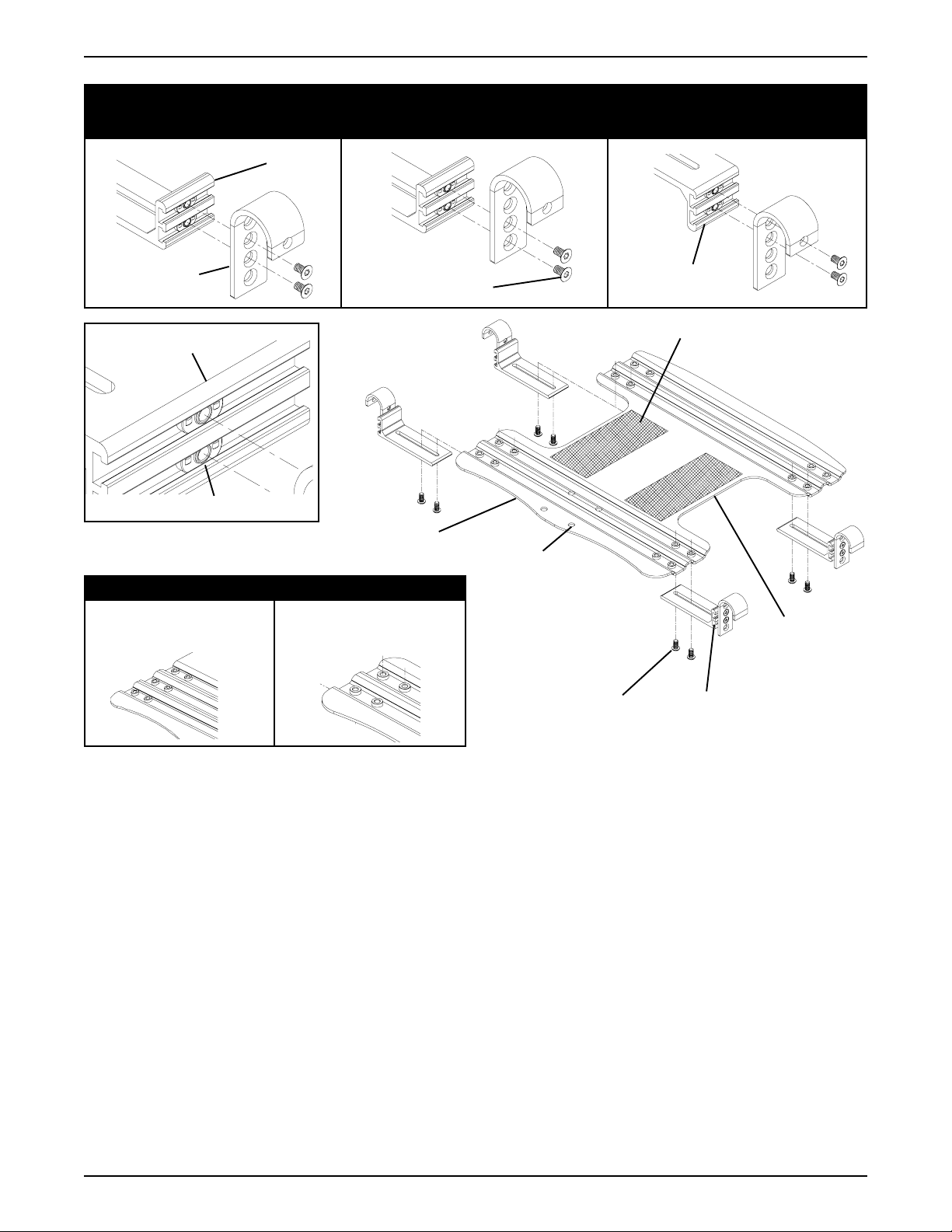
1-INCH (25MM) DROP (BASE
BRACKET POSITIONED UP)
Base
Bracket
2-INCH (50MM) DROP (BASE
BRACKET POSITIONED UP)
FLUSH MOUNTING (BASE
BRACKET POSITIONED DOWN)
Mounting
Hook
Base Bracket
Mounting Hook Glides
DETAIL "A"
18 AND 20-INCH DROP
BASE
Mounting Hook
Mounting Screws
Leg Cutout
Abductor Mounting Holes
ALL DEPTHS EXCEPT 18
AND 20-INCH
Hook and Loop Faces UP
TOWARDS FRONT
OF WHEELCHAIR
Base Bracket
Mounting Screws
Base Bracket
Rotated 180
TOWARDS REAR OF
Base Bracket - (Factory
Installed on Drop Base)
o
WHEELCHAIR
Crossbrace
Cutout
FIGURE 1 - ASSEMBLING/ADJUSTING DROP BASE, INSTALLING DROP BASE AND ADJUSTING DROP BASE
HEIGHT, WIDTH AND/OR ANGLE
4. Perform one (1) of the following:
BASE BRACKETS NEED TO BE REPOSITIONED
UP AND/OR DOWN:
A. Remove the two (2) mounting screws that secure
one (1) of the base brackets to the drop base.
o
B. Rotate base bracket 180
. Refer to FIGURE 1.
C. Line up the mounting holes in the base bracket
with the mounting holes in the drop base.
D. Reinstall the two (2) mounting screws that secure
one (1) base bracket to the drop base and tighten
securely.
E. Repeat STEPS A-D for remaining base brackets.
F. Continue with STEP 5.
BASE BRACKETS NEED TO BE REPOSITIONED
FORWARD AND/OR REAR WARD:
A. Remove the two (2) mounting screws that secure
one (1) of the base brackets to the drop base.
B. Perform one (1) of the following (DETAIL "A" of
FIGURE 1):
ALL BASE BRACKETS EXCEPT 18 AND 20-
INCH FRONT BASE BRACKETS - Reposition
the base bracket to one (1) of two (2) positions.
18 AND 20-INCH FRONT BASE BRACKETS -
Reposition the base bracket to one (1) of three
(3) positions.
C. Line up the mounting holes in the base bracket
with the mounting holes in the drop base.
D. Reinstall the two (2) mounting screws that se-
cure one (1) base bracket to the drop base and
tighten securely.
2
Page 3

E. Repeat STEPS 3-6 for the opposite front base
bracket.
BASE BRACKETS NEED TO BE REPOSITIONED
FOR SEA T WIDTH:
A. Loosen, but do not remove the two (2) mounting
screws that secure one (1) of the base brackets to
the drop base.
B. Continue with STEP 5.
BASE BRACKETS DO NOT NEED TO BE REPOSITIONED: continue to STEP 5.
5. Slide two (2) of the mounting hook glides into the base
brackets.
6. Position the mounting holes in the mounting hooks
determined in STEP 2 with the mounting hook glides
and loosely install two (2) of the mounting screws.
NOTE: Do not tighten the mounting screws at this time.
7. Repeat STEPS 5-6 for the remaining mounting hooks.
8. Install the drop base onto the wheelchair. Refer to IN-
ST ALLING DROP BASE in this instruction sheet and
perform STEPS 1-6.
INSTALLING DROP BASE (FIGURE 1)
1. Place the Drop Base on the wheelchair in the following position:
A. Crossbrace cutouts of the Drop Base approxi-
mately centered between the crossbraces.
B. The leg cutouts towards the front of the wheel-
chair.
C. The mounting hooks sitting flush with the cross-
braces of the wheelchair.
2. Test the rail clamps to make sure they secure the
drop base to the wheelchair.
NOTE: For proper operation of the rail clamps, refer to
instruction sheet part number 1074563.
NOTE: If the mounting hooks cannot be positioned to be
secured by the rail clamps, repeat STEPS 1-8 in AS-
SEMBLING/ADJUSTING DROP BASE in this instruction sheet.
NOTE: IF after repeating STEP 2 in this procedure and
STEPS 1-8 in ASSEMBLING/ADJUSTING DROP
BASE in this instruction sheet and the rail clamps do not
secure the drop base to the wheelchair, contact Technical Services at the numbers on the back of this instruction sheet.
3. Without moving seat and mounting hardware position, tighten all base bracket and hook mounting screws
securely.
4. Install the seat onto the drop base. Refer to the instructions provided with the seat for proper installation.
NOTE: It may be necessary to modify the seat to sit flush
on the drop base. Refer to the instructions provided with
the seat for proper installation.
ADJUSTING DROP BASE HEIGHT,
WIDTH AND/OR ANGLE
NOTE: This procedure is required only if the user and/or
wheelchair condition has changed.
1. Release the drop base from the rail clamps. Refer to
instruction sheet part number 1074563.
2. Lift up and remove drop base from the wheelchair.
3. Perform one (1) of the following:
ADJUSTING HEIGHT AND/OR ANGLE -
A. Remove the mounting screws that secure one
(1) of the mounting hook to the base bracket and
mounting hook glides.
B. Remove the mounting hook from the base bracket.
NOTE: The mounting hook glides will be loose in the
base bracket.
C. If necessary, repeat STEPS 1-2 for the remain-
ing mounting hooks.
D. Refer to ASSEMBLING/ADJUSTING DROP
BASE in this instruction sheet and perform STEPS
1-8.
ADJUSTING WIDTH -
A. Adjust the width of the wheelchair. Refer to the
wheelchair owner's manual.
B. Adjust the drop base to the new width. Refer to
ASSEMBLING/ADJUSTING DROP BASE in
this instruction sheet and perform STEPS 4-8.
DROP BASE INSPECTION/CLEANING
Inspection
W ARNING
DO NOT continue to use this product if any of the
following problems as described are discovered.
Corrective maintenance can be performed at or
arranged through your equipment supplier.
1. Once a week, visually inspect all parts for deformation, corrosion, breakage, wear and/or compression.
2. Periodically, check hook and loop fasteners for adhesion and engagement.
Cleaning
1. Once a week, clean with warm water and mild soap
solution. Wipe entire surface with a soft, clean cloth.
3
Page 4

LIMITED WARRANTY
PLEASE NOTE: THE W ARRANTY BELOW HAS BEEN DRAFTED TO COMPLY WITH FEDERAL LAW APPLICABLE TO
PRODUCTS MANUFACTURED AFTER JULY 4, 1975.
This warranty is extended only to the original purchaser/user of our products.
This warranty gives you specific legal rights and you may also have other legal rights which vary from state
to state.
Invacare warrants its product to be free from defects in materials and workmanship for a period of one
(1) year of use by original purchaser. With regard to the original puchaser/user only, Invacare warrants its
metal fabricated hardware components to be free from defects in materials and workmanship for the
lifetime of the product except any wood, foam plastic or upholstered components. If within such warranty period any such product shall be proven to be defective, such product shall be repaired or replaced, at Invacare's option. This warranty does not include any labor or shipping charges incurred in
replacement part installation or repair of any such product. Invacare's sole obligation and your exclusive
remedy under this warranty shall be limited to such repair and/or replacement.
For warranty service, please contact the dealer from whom you purchased your Invacare product. In
the event you do not receive satisfactory warranty service, please write directly to Invacare at the address below. Provide dealer's name, address, model number, date of purchase, indicate nature of the
defect and, if the product is serialized, indicate the serial number.
Invacare Corporation will issue a return authorization. The defective unit or parts must be returned for
warranty inspection using the serial number, when applicable, as identification within thirty (30) days of
return authorization date. DO NOT return products to our factory without our prior consent. C.O.D. shipments will be refused; please prepay shipping charges.
LIMIT A TIONS AND EXCLUSIONS: THE W ARRANTY SHALL NOT APPLY TO PROBLEMS ARISING FROM NORMAL
WEAR OR FAILURE TO ADHERE TO THE ENCLOSED INSTRUCTIONS. IN ADDITION, THE FOREGOING WARRANTY SHALL NOT APPL Y TO SERIAL NUMBERED PRODUCTS IF THE SERIAL NUMBER HAS BEEN REMOVED OR
DEFACED; PRODUCTS SUBJECTED TO NEGLIGENCE, ACCIDENT, IMPROPER OPERATION, MAINTENANCE
OR STORAGE; OR PRODUCTS MODIFIED WITHOUT INVACARE'S EXPRESS WRITTEN CONSENT INCLUDING,
BUT NOT LIMITED TO: MODIFICATION THROUGH THE USE OF UNAUTHORIZED PARTS OR ATTACHMENTS:
PRODUCTS DAMAGED BY REASON OF REPAIRS MADE TO ANY COMPONENT WITHOUT THE SPECIFIC
CONSENT OF INVACARE; PRODUCTS DAMAGED BY CIRCUMSTANCES BEYOND INVACARE'S CONTROL;
PRODUCTS REPAIRED BY ANYONE OTHER THAN AN AUTHORIZED INVACARE DEALER, SUCH EVALUATION
SHALL BE SOLELY DETERMINED BY INVACARE.
THE FOREGOING WARRANTY IS EXCLUSIVE AND IN LIEU OF ALL OTHER EXPRESS WARRANTIES, IF ANY, INCLUDING THE IMPLIED WARRANTIES OF MERCHANTABILITY AND FITNESS FOR A PARTICULAR PURPOSE.
IT SHALL NOT EXTEND BEYOND THE DURA TION OF THE EXPRESSED WARRANTY PROVIDED HEREIN AND THE
REMEDY FOR VIOLA TIONS OF ANY IMPLIED WARRANTY SHALL BE LIMITED TO REPAIR OR REPLACEMENT OF
THE DEFECTIVE PRODUCT PURSUANT TO THE TERMS CONT AINED HEREIN. INVACARE SHALL NOT BE LIABLE
FOR ANY CONSEQUENTIAL OR INCIDENTAL DAMAGES WHATSOEVER.
THIS WARRANTY SHALL BE EXTENDED TO COMPLY WITH STATE/PROVINCIAL LAWS AND REQUIREMENTS.
INVINV
AA
CC
INV
INVINV
Form No. 98-333 Part No. 1081825 Rev. B (1) - 4/99 Printed in U.S.A.
ARE CORPORAARE CORPORA
A
C
ARE CORPORA
AA
CC
ARE CORPORAARE CORPORA
INVACARE CANADA INVACARE CANADA
INVACARE CANADA l
INVACARE CANADA INVACARE CANADA
TION TION
TION l
TION TION
ONE ONE
WW
AA
ONE
ONE ONE
5970 Chedworth Way 5970 Chedworth Way
5970 Chedworth Way l
5970 Chedworth Way 5970 Chedworth Way
l
Phone 1-(800) 668-5324, 905-890-8300
Y INVY INV
W
A
Y INV
WW
AA
Y INVY INV
Phone 1-(800)-333-6900Phone 1-(800)-333-6900
l
Phone 1-(800)-333-6900
Phone 1-(800)-333-6900Phone 1-(800)-333-6900
AA
CC
A
C
AA
CC
ARE ARE
ARE l
ARE ARE
Mississauga Mississauga
Mississauga l
Mississauga Mississauga
PP
.O.O
..
Bo Bo
.O
.O.O
.
Bo
..
Bo Bo
x 4028 x 4028
x 4028 l
x 4028 x 4028
P
PP
ElyrElyr
ia,ia,
Ontario Canada L5R 3T9Ontario Canada L5R 3T9
Ontario Canada L5R 3T9
Ontario Canada L5R 3T9Ontario Canada L5R 3T9
Ohio 44036-2125 Ohio 44036-2125
Elyr
ia,
Ohio 44036-2125
ElyrElyr
ia,ia,
Ohio 44036-2125 Ohio 44036-2125
 Loading...