

Page 1
OWNER'S OPERATOR and
MAINTENANCE MANUAL
Allegro
Page 2

S
P
E
C
A
L
N
O
T
E
S
SPECIAL NOTES
WARNING/CAUTION notices as used in this manual apply to hazards or unsafe practices
which could result in personal injury or property damage.
I
THE INFORMATION CONTAINED IN THIS DOCUMENT IS SUBJECT TO CHANGE WITHOUT NOTICE.
WHEELCHAIR USER
As a manufacturer of wheelchairs, Invacare endeavors to supply a wide variety of wheelchairs to meet many needs of the end user . However , final selection of the type of wheelchair to be used by an individual rests solely with the user and his/her healthcare professional capable of making such a selection.
WHEELCHAIR TIE-DOWN RESTRAINTS AND SEA T RESTRAINTS
Invacare recommends that wheelchair users NOT be transported in vehicles of any kind
while in wheelchairs. As of this date, the Department of T ransportation has not approved
any tie-down systems for transportation of a user while in a wheelchair, in a moving
vehicle of any type.
SPECIAL NOTES
NOTICE
W
A
R
N
I
N
G
It is Invacare’s position that users of wheelchairs should be transferred into appropriate
seating in vehicles for transportation and use be made of the restraints made available
by the auto industry. Invacare cannot and does not recommend any wheelchair transportation systems.
AS REGARDS RESTRAINTS - SEA T BEL TS - IT IS THE OBLIGA TION OF THE DME DEALER,
THERAPISTS AND OTHER HEAL TH CARE PROFESSIONALS TO DETERMINE IF A SEA TING RESTRAINT IS REQUIRED TO ENSURE THE SAFE OPERATION OF THIS EQUIPMENT BY THE USER. SERIOUS INJURY CAN OCCUR IN THE EVENT OF A F ALL FROM A
WHEELCHAIR.
W ARNING
DO NOT OPERATE THIS EQUIPMENT WITHOUT FIRST READING AND
UNDERST ANDING THIS MANUAL. IF YOU ARE UNABLE T O UNDERSTAND
THE W ARNINGS, CAUTIONS, AND INSTRUCTIONS, CONTACT A
HEALTHCARE PROFESSIONAL, DEALER OR TECHNICAL PERSONNEL IF
APPLICABLE BEFORE ATTEMPTING TO USE THIS EQUIPMENT -
OTHERWISE INJURY OR DAMAGE MAY RESULT.
SAVE THESE INSTRUCTIONS.
2
Page 3

TABLE OF CONTENTS
T ABLE OF CONTENTS
SPECIAL NOTES ................................................................. 2
SAFETY SUMMARY ............................................................ 4
SAFETY/HANDLING OF WHEELCHAIRS ............................ 6
FEA TURES .........................................................................11
SPECIFICA TIONS .............................................................. 12
P ACKAGING...................................................................... 13
HANDLING ........................................................................ 13
SAFETY INSPECTION CHECKLIST ................................... 14
TROUBLESHOOTING........................................................ 15
MAINTENANCE ................................................................. 15
PROCEDURE 1 - FRONT RIGGINGS ................................. 16
INSTALLING FOOTRESTS............................................... 16
ADJUSTING FOOTREST HEIGHT .................................... 16
INSTALLING 3-INCH EXTENSION .................................... 17
INSTALLING ELEV ATING LEGRESTS .............................. 17
RAISING/LOWERING ELEVA TING LEGRESTS AND/OR
ADJUSTING CALFPADS ............................................... 17
INSTALLING/ADJUSTING ADJUST ABLE ANGLE
FLIP-UP FOOTPLATES ................................................. 18
REPLACING SECTOR BLOCK ........................................ 19
OPTIONAL FOOTREST ACCESSORIES .......................... 19
PROCEDURE 2 - ARMS ..................................................... 20
INSTALLING THE "T" ARM SOCKETS............................. 20
INSTALLING/REMOVING THE "T" ARMS ........................ 20
ADJUSTING THE "T" ARMS ............................................ 21
ADJUSTING THE TRANSFER ASSIST AND/OR SIDE
GUARDS - "T" ARMS .................................................... 22
REPLACING THE LOCKING LEVER - "T" ARMS ............. 23
USING/INSTALLING/HEIGHT ADJUSTMENT/
CORRESPONDING ARM ADJUSTMENT TO BACK
ANGLE - CANTILEVER ARMS ...................................... 24
REPLACING/REPOSITIONING THE LOCKING
MECHANISM IN THE CANTILEVER ARM ...................... 25
ARM P AD DEPTH ADJUSTMENT/REPLACEMENT -
CANTILEVER ARMS ..................................................... 25
INSTALLING F ABRIC CLOTHING GUARDS ..................... 26
INSTALLING RIGID SIDE GUARDS .................................. 26
ADJUSTING CONVENTIONAL ARM HEIGHT ,
REMOVING OR REPLACING CONVENTIONAL
ARMS............................................................................ 26
REPLACING ARMREST PADS......................................... 27
REPOSITIONING THE CONVENTIONAL ARMS ............... 27
PROCEDURE 3 - BACK ..................................................... 28
FOLDING/UNFOLDING THE BACK .................................. 28
REPLACING BACK UPHOLSTERY.................................. 28
ADJUSTING THE BACK HEIGHT ..................................... 32
REPLACING THE LOCKING MECHANISM
IN THE BACK CANE ..................................................... 33
CHANGING THE BACK ANGLE ....................................... 34
REPOSITIONING THE BACK
(CHANGING SEAT DEPTH) ........................................... 34
REPOSITIONING BACK FOR 2 OR 3-INCH SEA T
CUSHION - RECLINERS ONL Y...................................... 35
REPLACING FOLDING PUSH HANDLE - RECLINERS
ONLY ............................................................................... 36
INSTALLING AND REMOVING A SEA TING SYSTEM ....... 36
PROCEDURE 4 - SEAT ...................................................... 37
REPLACING SEAT UPHOLSTER Y ................................... 37
CHANGING/REPOSITIONING SEAT RAILS...................... 37
REPOSITIONING THE CROSSBRACES........................... 38
CHANGING SEAT WIDTH ................................................ 38
PROCEDURE 5 - CASTERS............................................... 41
REPLACING/REPOSITIONING/INST ALLING
FRONT CASTER ASSEMBLIES .................................... 41
RE PL A CI N G F R ON T F OR K ............................................. 41
REPLACING/REPAIRING FRONT CASTER TIRE/TUBE ... 42
o
90
ADJUSTMENT OF THE CASTER HEADTUBES ......... 42
CASTER HEADTUBE MOUNTING ADJUSTMENTS ......... 43
INSTALLING QUICK-RELEASE CASTERS....................... 44
PROCEDURE 6 - REAR WHEELS ...................................... 45
REMOVING/INST ALLING REAR WHEELS ....................... 45
ADJUSTING THE QUICK-RELEASE AXLE ...................... 45
INSTALLING THE QUAD-RELEASE AXLE ....................... 46
ADJUSTING THE QUAD-RELEASE HANDLE .................. 46
HANDRIM REPLACEMENT.............................................. 47
INSTALLING PROJECTION HANDRIMS .......................... 48
REPAIRING/REPLACING REAR WHEEL TIRE/TUBE....... 49
ADJUSTING THE WHEELBASE LENGTH........................ 49
ADJUSTING THE WHEELBASE WIDTH........................... 50
ADJUSTING REAR WHEEL HEIGHT ............................... 50
PROCEDURE 7 -WHEEL LOCKS/ANTI-TIPPERS .............. 51
ADJUSTING THE WHEEL LOCKS ................................... 51
WHEEL LOCK EXTENSION HANDLE INST ALLA TION ..... 51
INSTALLING/ADJUSTING THE ANTI-TIPPERS ................ 52
PROCEDURE 8 - RECLINER ............................................. 53
RECLINER OPERATION .................................................. 53
ADJUSTING THE RECLINER CABLES ............................ 54
REPLACING THE RECLINER CABLES ............................ 54
REPLACING THE GAS CYLINDERS ................................ 55
ADJUSTING THE GAS CYLINDERS ................................ 56
PROCEDURE 9 - SEAT-T O-FLOOR ................................... 57
SEAT-T O-FLOOR HEIGHT DETERMINA TION................... 57
CHANGING SEA T-TO-FLOOR HEIGHT ............................ 58
AXLE MOUNTING PLATE POSITIONS
FOR 20, 22 OR 24-INCH REAR WHEELS ...................... 59
INLINE CASTER HEADTUBE FRONT
SEAT-T O-FLOOR HEIGHTS .......................................... 60
OFFSET CASTER HEADTUBE FRONT
SEAT-T O-FLOOR HEIGHTS .......................................... 61
PROCEDURE 10 - SEAT DEPTH........................................ 62
SEAT DEPTH DETERMINATION ...................................... 62
CHANGING SEA T DEPTH ................................................ 62
SEAT DEPTH CHECKLIST............................................... 63
BACK, SEA T RAIL AND CROSSBRACE POSITIONS
FOR 12-INCH SEAT DEPTH .......................................... 64
BACK, SEA T RAIL AND CROSSBRACE POSITIONS
FOR 13-INCH SEAT DEPTH .......................................... 65
BACK, SEA T RAIL AND CROSSBRACE POSITIONS
FOR 14-INCH SEAT DEPTH .......................................... 66
BACK, SEA T RAIL AND CROSSBRACE POSITIONS
FOR 15-INCH SEAT DEPTH .......................................... 67
BACK, SEA T RAIL AND CROSSBRACE POSITIONS
FOR 16-INCH SEAT DEPTH .......................................... 68
BACK, SEA T RAIL AND CROSSBRACE POSITIONS
FOR 17-INCH SEAT DEPTH .......................................... 68
BACK, SEA T RAIL AND CROSSBRACE POSITIONS
FOR 18-INCH SEAT DEPTH .......................................... 69
WARRANTY ...................................................................... 71
T
A
B
L
E
O
F
C
O
N
T
E
N
T
S
3
Page 4

SAFETY SUMMARY
SAFETY SUMMAR Y
S
A
F
E
T
Y
S
U
M
M
A
R
Y
ST ABILITY
WARNING
The seat height, seat depth, back angle, seating system, size and position of the rear wheels, as well as the
user condition directly relate to the stability of the wheelchair. Any change to one (1) or any combination of
the seven (7) may cause the wheelchair to decrease in stability . These adjustments MUST be performed by
an authorized dealer or qualified technician.
OPERA TING INFORMATION
WARNING
T o determine and establish your particular safety limits, practice bending, reaching and transferring activities in several combinations in the presence of a qualified health professional BEFORE attempting active
use of the wheelchair.
Non-Recliners Only - Make sure the back is locked securely BEFORE using the wheelchair - otherwise
injury can occur.
DO NOT attempt to reach objects if you have to move forward in the seat.
DO NOT attempt to reach objects if you have to pick them up from the floor by reaching down between your
knees.
DO NOT lean over the top of the back upholstery to reach objects from behind as this may cause the
wheelchair to tip over.
DO NOT shift your weight or sitting position toward the direction you are reaching as the wheelchair may
tip over.
DO NOT tilt the wheelchair without assistance.
DO NOT use an escalator to move a wheelchair between floors. Serious bodily injury may occur.
DO NOT attempt to stop a moving wheelchair with the wheel locks. WHEEL LOCKS ARE NOT BRAKES.
Before attempting to transfer in or out of the wheelchair, every precaution should be taken to reduce the
gap distance. T urn both casters toward the object you are transferring onto. When transferring to and from
the wheelchair, AL WAYS ENGAGE BOTH WHEEL LOCKS.
DO NOT operate on roads, streets or highways.
o
DO NOT climb, go up or down ramps or traverse slopes greater than 9
DO NOT attempt to move up or down an incline with a water, ice or oil film.
DO NOT attempt to ride over curbs or obstacles. Doing so may cause your wheelchair to turn over and
cause bodily harm or damage to the wheelchair.
DO NOT use unauthorized parts, accessories, or adapters other than those authorized by Invacare.
DO NOT attempt to lift a wheelchair by lifting on any removable (detachable) parts. Lifting by means of any
removable (detachable) parts of a wheelchair may result in injury to the user or damage to the wheelchair.
NEVER try to lift or tip the wheelchair by cantilever arms or "T" arms, serious injury can occur.
DO NOT stand on the frame of the wheelchair.
Anti-tippers MUST BE attached at all times.
DO NOT use the footplate as a platform when getting in or out of the wheelchair.
.
ALW A YS wear your seat restraint. Inasmuch as the SEA T RESTRAINT is an option on this wheelchair (Y ou
may order with or without the seat restraint), Invacare strongly recommends ordering the seat restraint as
an additional safeguard for the wheelchair user.
4
Page 5

SAFETY SUMMARY (continued)
SAFETY SUMMARY
WARNING
TIRE PRESSURE
DO NOT use your wheelchair unless it has the proper tire pressure (p.s.i.). DO NOT overinflate the tires.
Failure to follow these suggestions may cause the tire to explode and cause bodily harm.
Replacement of a tire or tube MUST be performed by an authorized Invacare Dealer or Qualified Technician.
WEIGHT TRAINING
Invacare DOES NOT recommend the use of its wheelchairs as a weight training apparatus. Invacare
wheelchairs have NOT been designed or tested as a seat for any kind of weight training. If occupant uses
said wheelchair as a weight training apparatus, Invacare shall NOT be liable for bodily injury and the
warranty will be voided immediately .
WEIGHT LIMIT ATION
The Allegro wheelchair weight limitations are: Folding Frames - 250 lbs., Rigid Frames - 150 lbs.
RECLINER OPTION ONLY:
WARNING
Before using ANY recline position of this wheelchair, make sure the rear wheels are in the MOST
REARW ARD position in the Extended Multi-Position axle plate to maintain the stability of the wheelchair. Do not change the handling/maneuverability of the wheelchair by moving the rear wheels to
ANY of the forward positions. Moving the rear wheels to ANY of the forward positions WILL change
the center of gravity of the wheelchair, making the wheelchair less stable.
o
AL W AYS make sure that the wheelchair is stable in the FULL RECLINED (back at 170
the FULL UPRIGHT (back at 90o) position BEFORE using the recliner option.
) position AND
S
A
F
E
T
Y
S
U
M
M
A
R
Y
NEVER use the Standard Multi-Position or Offset Multi-Position axle plates with the recliner option.
Using the Standard Multi-Position or Offset Multi-Position axle plates WILL reduce the stability of the
wheelchair, causing injury to the user and/or assistant(s).
Before using the recliner option, make sure the anti-tipper wheel assemblies are in the lowest adjustment hole (adjustment hole closest to the ground/floor).
ALWAYS use the seat restraint.
ALWAYS engage both wheel locks while reclining or inclining (reverse recline) the wheelchair.
Both gas cylinders MUST be operational and adjusted properly BEFORE using recliner. DO NOT
operate the recliner option if only one (1) of the gas cylinders is operational or adjusted properly.
NEVER use the rear two (2) recliner bracket mounting holes when using the recliner option.
Using the rear two (2) recliner bracket mounting holes WILL make the wheelchair less stable,
possibly causing injury.
Make sure the patient is properly positioned in the wheelchair before reclining or inclining (reverse recline) to maintain maximum stability and safety . Refer to the SAFETY/HANDLING section
of this manual.
When returning the occupant of the wheelchair to the full upright position, more body strength
will be required for approximately the last twenty (20) degrees of incline (reverse recline). Make
sure to use proper body mechanics (use your legs) or seek assistance to avoid injury.
5
Page 6

SAFETY/HANDLING
SAFETY/HANDLING OF WHEELCHAIRS
S
A
&
H
A
N
D
N
G
“Safety and Handling” of the wheelchair requires the close
attention of the wheelchair user as well as the assistant.
This manual points out the most common procedures
F
and techniques involved in the safe operation and main-
E
tenance of the wheelchair. It is important to practice and
T
master these safe techniques until you are comfortable
Y
in maneuvering around the frequently encountered architectural barriers.
Use this information only as a “basic” guide. The techniques that are discussed on the following pages have
been used successfully by many.
Individual wheelchair users often develop skills to deal
L
with daily living activities that may differ from those de-
I
scribed in this manual. Invacare recognizes and encourages each individual to try what works best for him/her in
overcoming architectural obstacles that they may encounter. Techniques in this manual are a starting point for the
new wheelchair user and assistant with “safety” as the
most important consideration for all.
ST ABILITY AND BALANCE
WARNING
ALW AYS wear your seat restraint. Inasmuch as the
SEAT RESTRAINT is an option on this wheelchair
(You may order with or without the seat restraint),
Invacare strongly recommends ordering the seat
restraint as an additional safeguard for the wheelchair user.
To assure stability and proper operation of your wheelchair, you must at all times wear your seat restraint and
maintain proper balance. Your wheelchair has been designed to remain upright and stable during normal daily
activities as long as you do not move beyond the center
of gravity.
DO NOT lean forward out of the wheelchair any further
than the length of the armrests. Make sure the casters
are pointing in the forward position whenever you lean
forward. This can be achieved by advancing the wheelchair and then reversing it in a straight line.
A NOTE TO WHEELCHAIR ASSIST ANTS
When assistance to the wheelchair user is required, remember to use good body mechanics. Keep your back
straight and bend your knees whenever tilting the wheelchair or traversing curbs, or other impediments.
Also, be aware of any removable (detachable) parts.
These must NEVER be used for hand-held or lifting supports, as they may be inadvertently released, resulting in
possible injury to the user and/or assistant(s).
When learning a new assistance technique, have an experienced assistant help you before attempting it alone.
TIL TING
WARNING
DO NOT tilt the wheelchair without assistance.
When tilting the wheelchair, an assistant should grasp
the back of the wheelchair on a non-removable (nondetachable) part. Inform the wheelchair occupant before
tilting the wheelchair and remind him/her to lean back. Be
sure the occupant’s feet and hands are clear of all wheels.
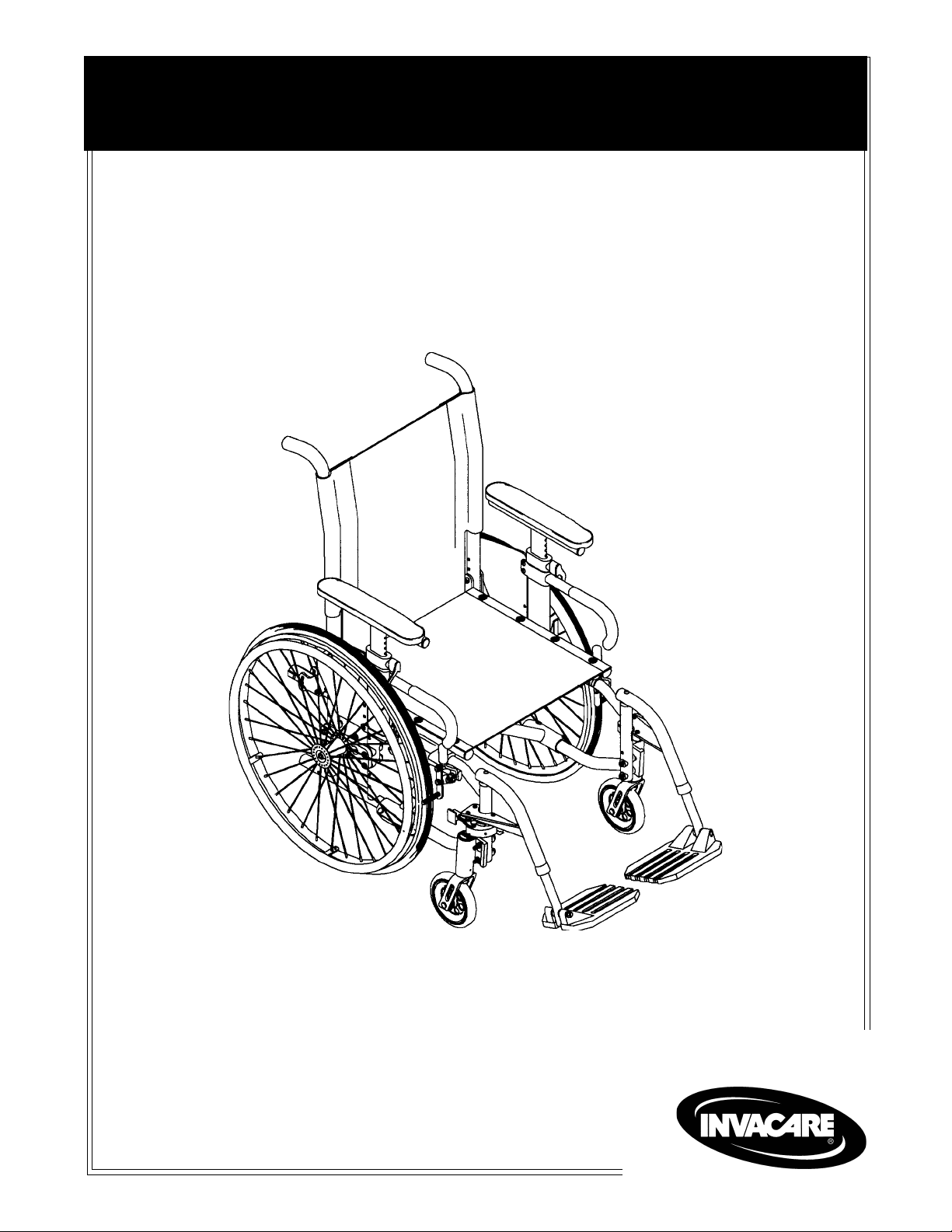
TIL TING - CURBS:
After mastering the techniques of tilting the wheelchair,
use this procedure to tackle curbs, short stairs, etc.
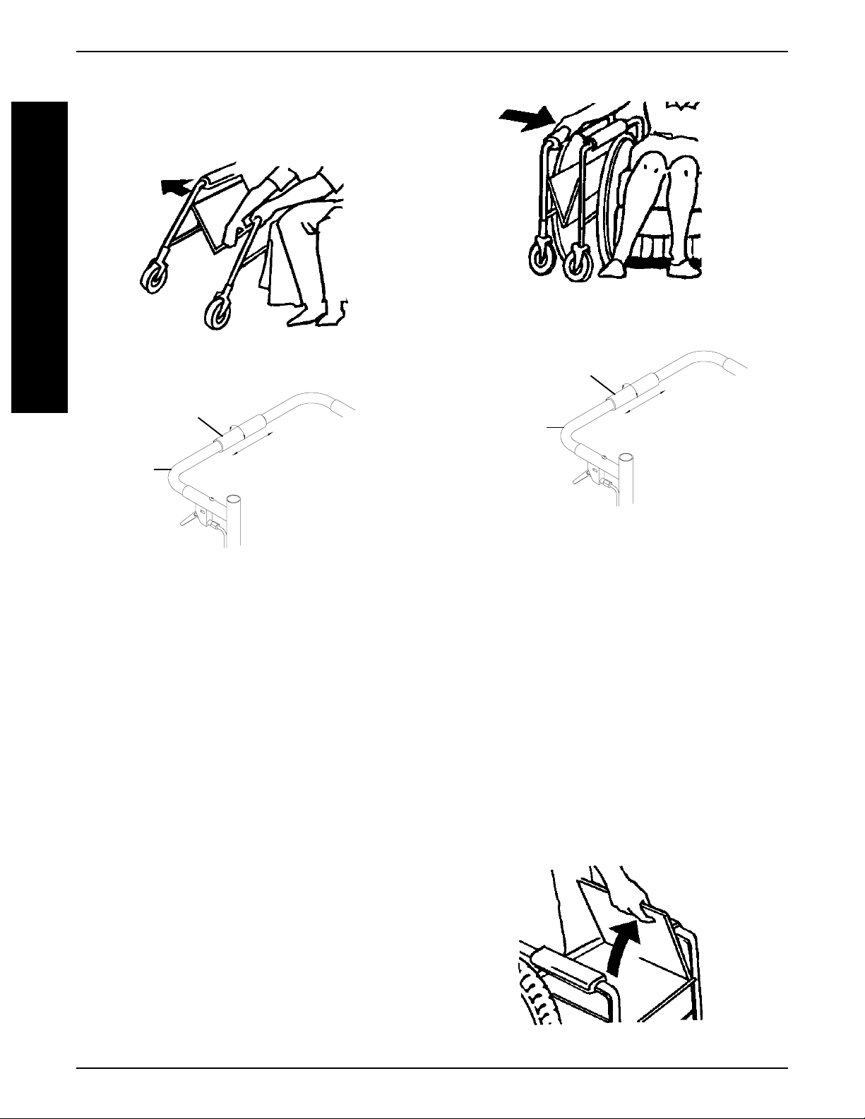
Method 1 - Wheelchairs With Step T ubes
Apply a continuous downward motion until the balance
point is achieved and the front casters clear the curb. At
this point, the assistant will feel a difference in the weight
distribution.
Roll the wheelchair forward and slowly lower the wheelchair in one continuous movement onto the sidewalk. Do
not let the wheelchair drop the last few inches to the
ground. This could result in injury to the occupant. Push
the wheelchair forward until the rear wheels roll up and
over the curb.
COPING WITH EVERYDAY OBST ACLES
Coping with the irritation of everyday obstacles can be
alleviated somewhat by learning how to manage your
wheelchair. Keep in mind your center of gravity to maintain stability and balance.
METHOD 1 - WHEELCHAIR WITH STEP TUBES
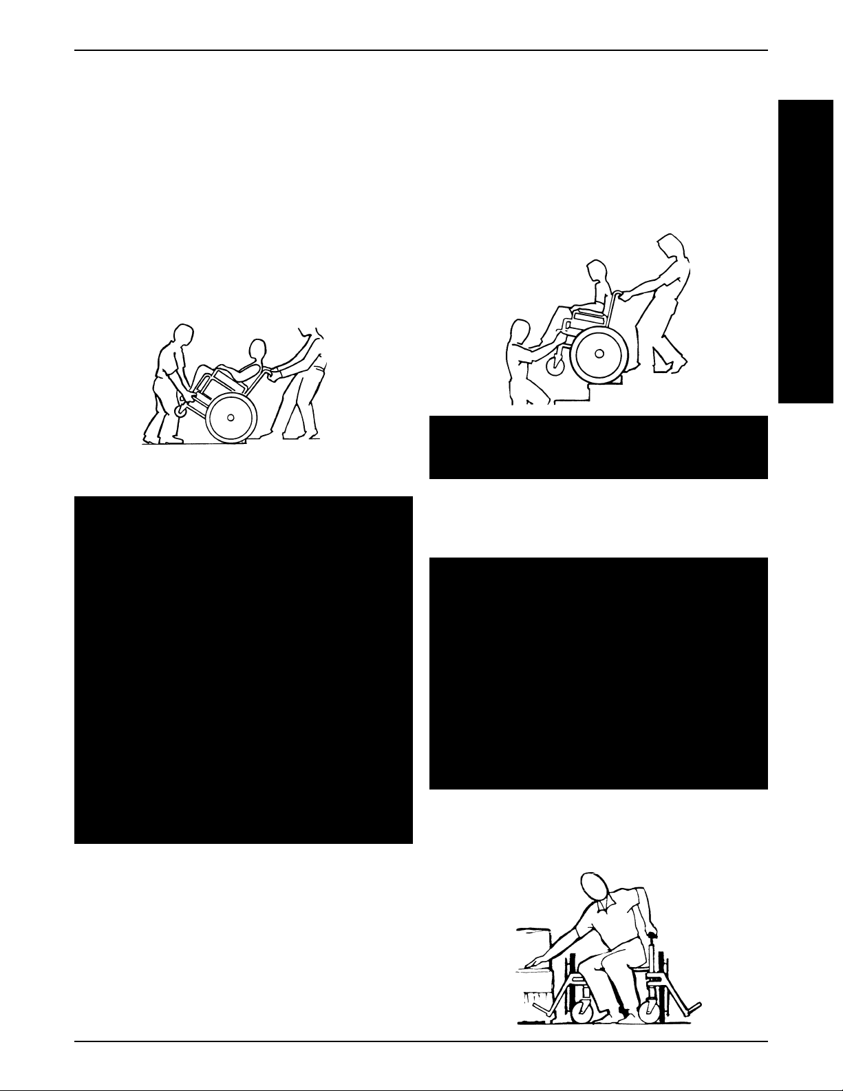
Method 2 - Wheelchairs Without Step T ubes
Unless the first assistant has exceptional upper body
strength, it is recommended that METHOD 2 use two (2)
assistants.
6
Page 7
SAFETY/HANDLING
The second assistant should be positioned at the front of
the wheelchair lifting upward on a non-removable (nondetachable) part of the wheelchair frame when lifting the
wheelchair and stabilizing the wheelchair when the wheelchair is being lowered to the ground.
The first assistant should stand on the sidewalk and turn
the wheelchair so that the rear wheels are against the
curb. The wheelchair should be tilted back to the balance
point and, in one continuous downward movement, the
rear wheels should be pulled up and over the curb. DO
NOT return the front casters to the ground until the wheelchair has been pulled backward far enough for the front
casters to clear the edge of the curb.
METHOD 2 - WHEELCHAIR WITHOUT STEP TUBE
ST AIRW A YS
2. The second assistant, with a firm hold on a non-detachable part of the framework, lifts the wheelchair
up and over the stair and steadies the wheelchair as
the first assistant places one (1) foot on the next stair
and repeats STEP 1.
3. The wheelchair should not be lowered until the last
stair has been negotiated and the wheelchair has
been rolled away from the stairway.
ESCALA TORS? SORR Y!
DO NOT use an escalator to move a wheelchair
between floors. Serious bodily injury may occur.
S
A
F
E
T
Y
&
H
A
N
D
L
I
N
G
WARNING
Do not attempt to lift a wheelchair by lifting on any
removable (detachable) parts. Lifting by means of
any removable (detachable) parts of a wheelchair
may result in injury to the user or damage to the
wheelchair.
Extreme caution is advised when it is necessary to
move an occupied wheelchair up or down the stairs.
Invacare recommends using two (2) assistants and
making thorough preparations. Make sure to use
ONLY secure, non-detachable parts for hand-held
supports.
ALW AYS wear your seat restraint. Inasmuch as the
SEAT RESTRAINT is an option on this wheelchair
(You may order with or without the seat restraint),
Invacare strongly recommends ordering the seat
restraint as an additional safeguard for the wheelchair user.
Follow this procedure for moving the wheelchair between floors when an elevator is NOT available:
1. After the wheelchair has been tilted back to the balance point, one assistant (in the rear) backs the wheelchair up against the first step, while securely grasping a non-removable (non-detachable) part of the
wheelchair for leverage.
TRANSFERRING TO AND FROM OTHER
SEA TS
WARNING
BEFORE attempting to transfer in or out of the
wheelchair, every precaution should be taken to
reduce the gap distance. T urn both casters toward
the object you are transferring onto. Also be certain the wheel locks are engaged to help prevent
the wheels from moving.
CAUTION
When transferring, position yourself as far back as
possible in the seat. This will prevent damaged
upholstery and the possibility of the wheelchair tipping forward.
NOTE: This activity may be performed independently
provided you have adequate mobility and upper body
strength.
7
Page 8
S
A
&
H
A
N
D
N
G
SAFETY/HANDLING
Position the wheelchair as close as possible along side
the seat to which you are transferring, with the front casters pointing toward it. Engage wheel locks. Shift body
weight into seat with transfer.
F
During independent transfer, little or no seat platform will
E
be beneath you. Use a transfer board if at all possible.
T
Y
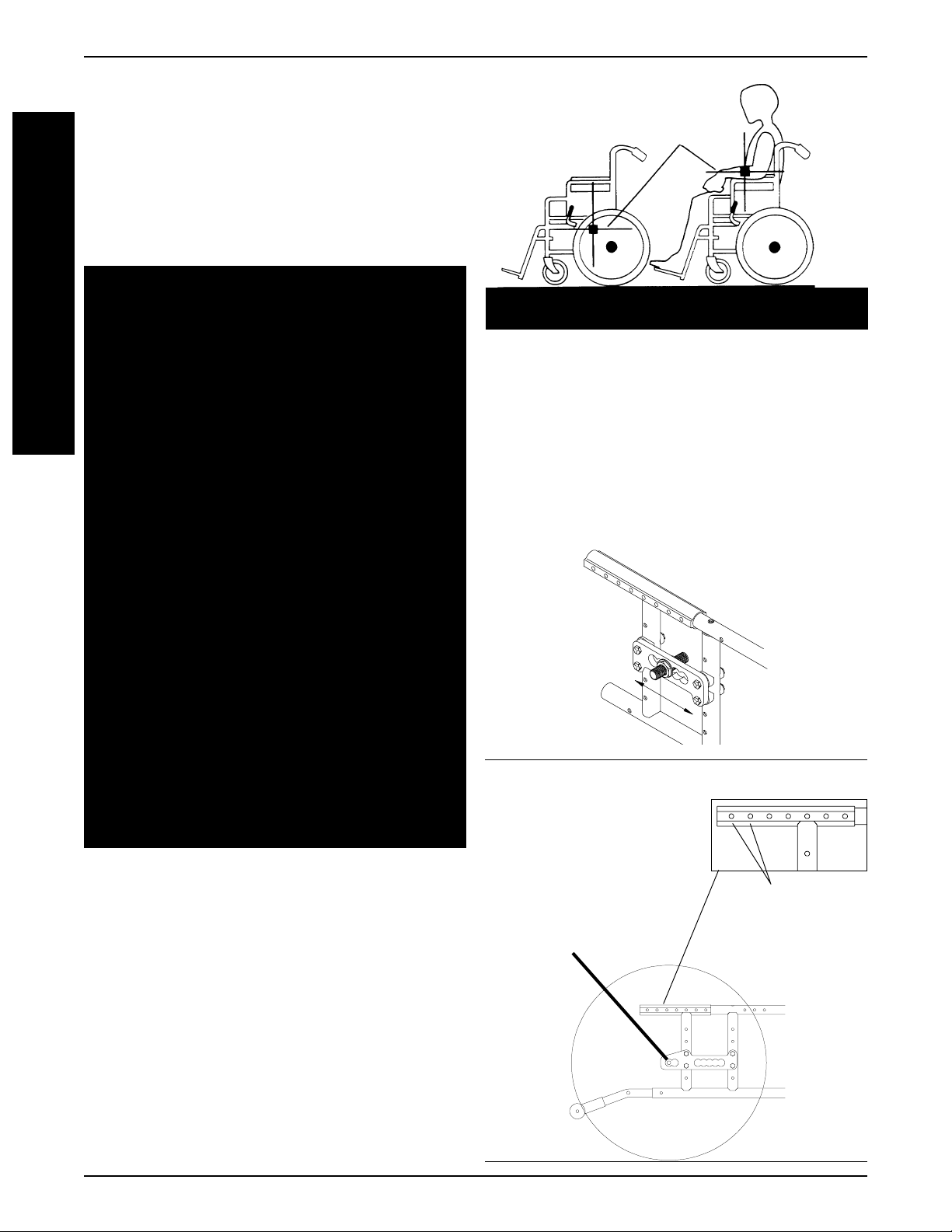
PERCENT AGE OF WEIGHT DISTRIBUTION
WARNING
DO NOT attempt to reach objects if you have to move
forward in the seat or pick them up from the floor by
reaching down between your knees.
L
I
The seat height, seat depth, back angle, seating system, size and position of the rear wheels, as well as
the user condition directly relate to the stability of
the wheelchair. Any change to one (1) or any combination of the seven (7) may cause the wheelchair to
decrease in stability. These adjustments MUST be
performed by an authorized dealer or qualified technician.
RECLINERS ONL Y : Before using ANY recline position of this wheelchair, make sure the rear wheels
are in the MOST REARWARD position in the Extended Multi-Position axle plate to maintain the stability of the wheelchair. Do not change the handling/
maneuverability of the wheelchair by moving the
rear wheels to ANY of the forward positions. Moving the rear wheels to ANY of the forward positions
WILL change the center of gravity of the wheelchair,
making the wheelchair less stable.
CENTER OF
GRAVITY
Example 46% 54% 103 lbs. 130 lbs.
UNOCCUPIED OCCUPIED
Lengthening the Wheelbase will increase stability and
maintain standard maneuverability of the wheelchair.
Shortening the Wheelbase will increase maneuverability
and distribute additional weight onto the rear wheels.
Centering the Wheelbase gives you maneuverability
and stability.
NON-RECLINERS
Lengthening
(Rearward)
Shortening
(Forward)
RECLINERS ONLY: NEVER use the rear two (2) recliner bracket mounting holes when using the recliner option. Using the rear two (2) recliner bracket
mounting holes WILL make the wheelchair less
stable, possibly causing injury .
Many activities require the wheelchair owner to reach,
bend and transfer in and out of the wheelchair. These
movements will cause a change to the normal balance,
the center of gravity, and the weight distribution of the
wheelchair. To determine and establish your particular
safety limits, practice bending, reaching and transferring
activities in several combinations in the presence of a
qualified health professional BEFORE attempting active
use of the wheelchair.
Proper positioning is essential for your safety. When reaching, leaning, bending forward, it is important to use the
front casters as a tool to maintain stability and balance.
Make sure the rear
wheels are in the
MOST REARW ARD
position to main-
tain the stability of
the wheelchair
8
RECLINERS
xx
NEVER use the
rear two (2)
Recliner Bracket
Mounting Holes
Page 9
SAFETY/HANDLING
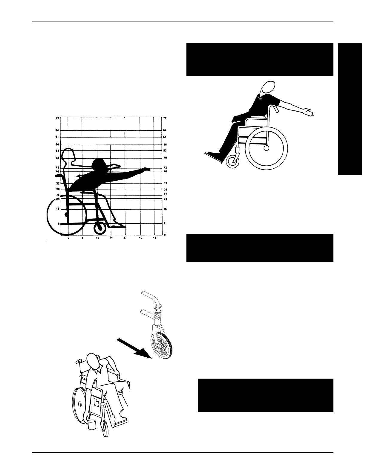
FUNCTIONAL REACH FROM A
WHEELCHAIR
The approximate reach-limit values shown in the
accompanying graph were derived on the basis of
a sample of 91 male and 36 female subject wheelchair users. Note the difference between the maximum and the comfortable reach limits, a subjective
but important consideration in design.
FORWARD REACH
(Adults)
COMFORTABLE
MAXIMUM
INCHES
REACHING, LEANING - BACKWARDS
WARNING
DO NOT lean over the top of the back upholstery. This will change your center of gravity
and may cause you to tip over.
Position wheelchair as close as possible to the desired
object. Point front casters forward to create the longest
possible wheelbase. Reach back only as far as your arm
will extend without changing your sitting position.
S
A
F
E
T
Y
&
H
A
N
D
L
I
N
G
INCHES
REACHING, LEANING and
BENDING - FORW ARD
Position the front casters
so that they are extended
as far forward as possible
and engage wheel locks.
DO NOT LEAN FORWARD OF THE ARMRESTS.
FOLDING AND UNFOLDING THE
WHEELCHAIR
WARNING
Keep hands and fingers clear of moving parts to
avoid injury .
Sling Seat Model Wheelchairs
UNFOLDING.
1. Grasp the push handle of the wheelchair closest
to you.
2. Tilt the wheelchair towards you (raising the opposite wheel and caster off the ground/floor).
3. Push downward on the seat rail closest to you
where the seat upholstery is attached until the
wheelchair is fully open.
4. RECLINERS ONLY A. Slide the cover of the folding handle over the
links in the center of the spreader bar.
CAUTION
Do not overtighten the cover of the folding
handle. Damage to the folding handle will occur .
B. Turn the folding handle cover towards the front
of the wheelchair approximately two (2) to four
(4) revolutions.
9
Page 10
S
A
&
H
A
N
D
N
G
SAFETY/HANDLING
5. Engage both wheel locks, open the footrest/
legrest for clearance and transfer into the wheelchair. Refer to TRANSFERRING TO AND FROM
F
E
T
Y
L
I
OTHER SEATS in this section of the manual.
RECLINERS ONL Y
Cover of the
Folding Handle
To Fold
Folding
To Unfold
Handle
RECLINERS ONL Y
Cover of the
Folding Handle
Folding
Handle
To Fold
To Unfold
SLING SEA T MODEL WHEELCHAIRS -
UNFOLDING
FOLDING.
1. Swing footrest/legrest in locked position to the
front of the wheelchair.
2. Pivot footplates upward to vertical position.
3. RECLINERS ONLY A. Turn the folding handle cover towards the
rear of the wheelchair approximately two (2)
to four (4) revolutions.
B. Slide the cover of the folding over until the
links of the spreader bar are visible.
4. With both hands, grasp the middle of the seat
upholstery at the front and back edge and lift
up. Or, tilt the wheelchair to one side and close
by the push handles.
NOTE: If wheelchair is equipped with carry
straps, the wheelchair may be closed by pulling
up on the straps.
SLING SEA T MODEL WHEELCHAIRS -
FOLDING
Solid Seat Model Wheelchairs
1. From behind the wheelchair, grasp the right hand
edge of the solid seat.
2. Raise the seat to the hinged side.
3. Swing footrest/legrest in locked position to the
front of the wheelchair.
4. Pivot footplates upward to vertical position.
5. With both hands, grasp the middle of the seat
upholstery at the front and back edge and lift
up. Or, tilt the wheelchair to one side and close
by the push handles.
10
SOLID SEA T MODEL WHEELCHAIRS
Page 11
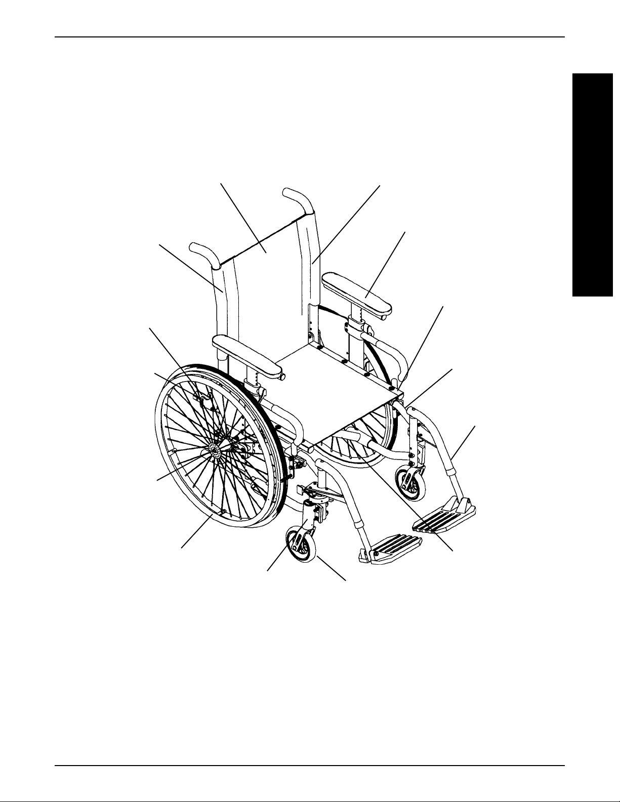
FOLDING BACK -
ANTERIOR OR
POSTERIOR DIRECTION
ADJUST ABLE OR FIXED
HEIGHT BACK
SQUARED OFF
TUBING FOR
BACK CANES
FEATURES
20o POSTERIOR TO 10o ANTERIOR RECLINE
RECLINE ADJUST ABLE BACK -
"T", CANTILEVER OR DUAL
POINT ADJUST ABLE HEIGHT
ARMS -
"T" SHOWN
GROWABLE WITH MODULAR
CROSSBRACES - 12-18-INCH
SEAT DEPTHS
FEATURES
F
E
A
T
U
R
E
S
DEPTH
ADJUSTABLE
BACK
MULTI-POSITION,
EXTENDED
MULTI-POSITION
OR OFFSET AXLE
MOUNTING PLATES
20, 22 OR 24-INCH
REAR WHEELS
TWO (2) CHOICES OF
HEADTUBES
ONE-PIECE SIDE
FRAMES -
SHORT, MEDIUM OR
LONG
ALL ACTION FRONT
RIGGINGS
FOLDING OR RIGID
3, 5, 6 or 8-INCH FRONT CASTERS
11
Page 12

SPECIFICATIONS
SPECIFICATIONS
S
P
E
C
F
C
A
T
O
N
S
PHYSICAL SPECIFICATIONS
Overall Width:
Overall Depth (w/o front riggings):
I
Frame Depth:
I
I
Seat Width:
Seat Depth:
Crossbrace Type:
Frame T ype:
✪ Seat-to-Floor:
Back Style and Height:
Back Angle Range (Recliner Only):
Arm Styles:
Footrest:
Rear Axle:
Rear Axle Mounting Plates:
Rear Wheels:
Handrims:
Caster Size:
Wheel Locks:
Frame Colors:
Upholstery:
Weight:
Shipping Weight (approx.):
OPEN - Seat Width plus approximately 9-inches
CLOSED - 14-inches (with back upholstery)
25-inches (20-inch rear wheels and casters in trailing position) to
35-inches (24-inch rear wheels and casters in leading position)
Short - 14-inches, Medium - 16-inches, Long - 18-inches
12-18-inches for Standard Folding Frames and 12-16-inches - Rigid Frame
(in one [1] inch increments)
12-18-inches (in one [1] inch increments)
Modular, Rigid or Less Seat Rails
Aluminum, One-piece. Available as Standard Folding Frame, Folding Frame w/o Seat
Rails or Rigid Frame w/o Seat Rails
REAR Seat-to-Floor Range (in inches) FRONT Seat-to-Floor Range (in inches)
20-inch rear wheels - 14-3/4 to 19-1/4 3-inch Front Casters - 15 to 18-3/4
22-inch rear wheels - 15-3/4 to 20-1/4 5-inch Front Casters - 16 to 19-3/4
24-inch rear wheels - 16-1/2 to 21 6-inch Front Casters - 17 to 20-1/4
Adjustable Angle (80
- Adjustable Height 10o Cane w/Push Handles - 14-18-inch Height Range
- Adjustable Height Straight Cane w/Push Handles - 12-18-inch Height Range
- Adjust. Height Sportster Cane (No Push Handles) - 10-14-inch Height Range
- Fixed Height Anodized Cane w/Push Handles - 16, 17, 18, 19 or 20-inch
Recliner - 18, 20 or 24-inch
o
to 170
o
90
"T" (Standard), Cantilever (Fixed Height Anodized Cane w/Push Handles Only) or
Conventional (Dual Point Adjustable Height)
Swingaway Footrests and Elevating Legrests
Quick-Release, Quad-Release or Permanent
Non-Recliner Wheelchairs - Multi-Position - Standard, Extended Multi-Position or
Recliner Wheelchairs - Extended Multi-Position
20, 22 and 24-inch Composite or Spoke Urethane, Pneumatic or Pneumatic with Flat Free Insert
Aluminum, Plastic Coated and Projection
3 or 5-inch Aluminum or Composite Urethane
6 or 8-inch Composite Urethane, Pneumatic or Pneumatic w/Flat Free Insert
Push-To-Lock, Pull-To-Lock, Wheel Lock Extensions, Hill Holder
Wet Black, Red, Super Teal, Sunny Yellow, Chrome, Pink Pearl, Metallic Blue, Deep
Purple, Anthracite, Metallic Green, Cobalt Blue, White, Lollipop Pink, Silver Vein, Passion Purple, Shocking Blue, Hot Red, Grey Veil, Green Veil, Dark Purple, Gold Veil,
Black w/Twilight Sparkle, Black w/Red Sparkle, Black w/Green Sparkle, Black w/Blue
Sparkle, Black w/Gold Sparkle
U240 Nylon - Black
27-29 lbs. - without front riggings
37-39 lbs.
o
to 110o), Fold Down
ALLEGRO
8-inch Front Casters - 18-3/4 to 21-1/4
Offset Multi-Position
✪ ✪
✪ NOTE: Invacare recommends that rear seat-to-floor height be A T LEAST 3/8-inch shorter than front seat-
✪ ✪
to-floor height. Otherwise a forward seat dump can occur. The rear seat-to-floor heights are based on
pneumatic tires and pneumatic tires with flat free inserts. If wheelchair is equipped with urethane tires,
subtract 1/4-inch from the measurements listed above. All heights are approximate to +1/4-inch due to tire
wear and air pressure. The front seat-to-floor heights are approximate to +1/4-inch.
12
Page 13
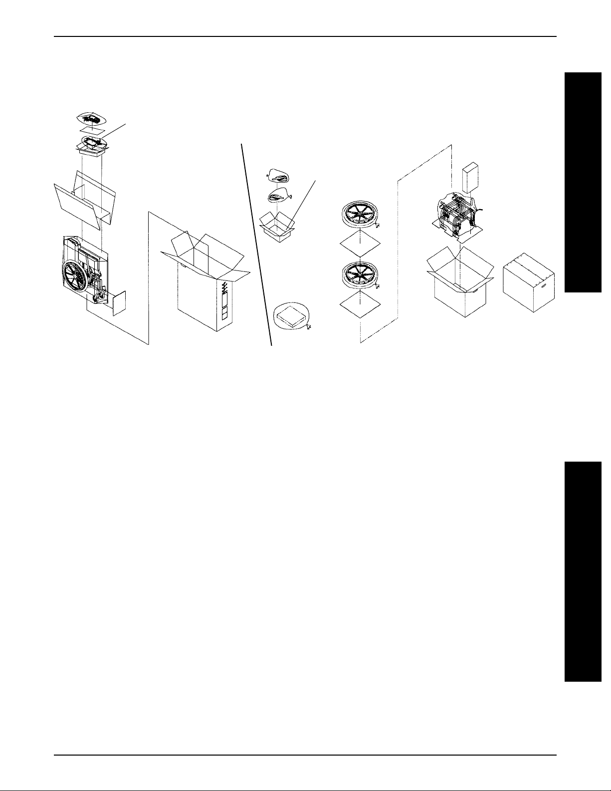
PACKAGING
PACKAGING/HANDLING
Accessory Carton
ALLEGRO FOLDING FRAMES
WITH AND WITHOUT SEA T RAILS
P
A
C
K
Accessory Carton
A
G
I
N
G
ALLEGRO RIGID FRAME
HANDLING
UNPACKING
1. Check for any obvious damage to the carton or
its contents. If damage is evident, notify your
Dealer/Carrier.
2. Remove all loose packing from the carton.
3. Carefully remove all components from the
carton.
NOTE: Unless the Allegro
immediately , retain cartons and packing materials for use in storing the wheelchair until
assembly is required.
is to be assembled
INSPECTION
1. Examine exterior of the Allegro for nicks, dents,
scratches or other damages. Inspect all components. If damage is evident, notify your Dealer/
Carrier.
STORAGE
1. Store the packaged/repackaged Allegro in a dry
area.
2. DO NOT place other objects on top of the packaged/repackaged wheelchair.
13
H
A
N
D
L
I
N
G
Page 14

N
C
O
N
SAFETY INSPECTION CHECK LIST
SAFETY INSPECTION CHECKLIST
S
A
F
E
T
Y
S
P
E
T
NOTE: T wice a year take your wheelchair to a qualified dealer for a thorough inspection and servicing. Regular
cleaning will reveal loose or worn parts and enhance the smooth operation of your wheelchair. To operate
properly and safely, your wheelchair must be cared for just like any other vehicle. Routine maintenance will
extend the life and efficiency of your wheelchair.
Initial adjustments should be made to suit your personal body structure and preference. Thereafter follow these maintenance procedures:
I
ITEM
INITIALLY
INSPECT/
ADJUST
WEEKLY
INSPECT/
ADJUST
MONTHLY
PERIODICALL Y
GENERAL
● Wheelchair rolls straight (no excessive drag or pull to one side).
X
X
SEA T AND BACK (PROCEDURES 3 and 4)
I
● Inspect for rips or sagging.
● Inspect fastening flaps to ensure they securely latch.
● Inspect modular seat rail attaching hardware is securely tightened.
● Inspect back mounting plate attaching hardware is securely tight-
ened.
● Inspect back fold down mechanisms to ensure they securely latch.
X
X
X
X
X
X
REAR WHEELS (PROCEDURE 6)
● No excessive side movement or binding when lifted and spun.
● Quick/Quad-release axles lock properly.
X
X
X
HANDRIMS (PROCEDURE 6)
● Inspect for signs of rough edges or peeling.
X
SPOKES
● Inspect for broken spokes.
X
X
FRONT CASTER (PROCEDURE 5)
● Inspect wheel/fork assembly for proper tension by spinning caster;
caster should come to a gradual stop.
● Loosen/tighten locknut if wheel wobbles noticeably or binds to a
stop.
● Wheel bearings are clean and free of moisture.
X
X
X
X
X
X
CAUTION: As with any vehicle, the wheels and tires should be
checked periodically for cracks and wear, and should be replaced when necessary .
TIRES (PROCEDURES 5 and 6)
● Inspect for flat spots and wear.
● If pneumatic tires, check for proper inflation (recommended tire pres-
sure is listed on the side wall of the tire).
X
X
X
X
CAUTION: As with any vehicle, the wheels and tires should be
checked periodically for cracks and wear, and should be replaced when necessary .
WHEEL LOCKS (PROCEDURE 7)
● Do not interfere with tires when rolling.
● Pivot points free of wear and looseness.
● Wheel locks easy to engage.
TRIGGER RELEASE LEVER/ CABLE (PROCEDURE 8)
● Cables completely release and handles return when released.
GAS CYLINDERS - PROCEDURE 8
● Inspect for leaking oil.
CLEANING
● Clean upholstery and armrests.
X
X
X
X
X
X
X
X
INSPECT/
ADJUST
X
X
X
X
X
X
X
X
X
X
X
X
X
14
Page 15

TROUBLESHOOTING/MAINTENANCE
TROUBLESHOOTING
CHAIR CHAIR SLUGGISH CASTERS SQUEAKS LOOSENESS CHAIR SOLUTIONS
VEERS VEERS TURN OR FLUTTERS AND IN CHAIR 3 WHEELS
RIGHT LEFT PERFORMANCE RATTLES
XX X X XIf pneumatic, check tires
for correct and equal
pressure.
XXXX Check for loose stem
nuts and bolts.
XX X Check that both casters
contact the ground at
the same time.
MAINTENANCE
MAINTENANCE SAFETY PRECAUTIONS
WARNING
After adjustments and before use, make sure
all attaching hardware is securely tightened.
DO NOT overtighten hardware attaching to the
frame. This could cause damage to the frame
tubing.
Do not use the wheelchair unless it has the
proper tire pressure (p.s.i.). DO NOT overinflate
the tires. Failure to follow these suggestions
may cause the tire to explode and cause bodily
harm.
5. If tires are pneumatic, recommended tire pressure is listed on the side wall of the tire.
WARNING
T
R
O
U
B
L
E
S
H
O
O
T
I
N
G
SUGGESTED MAINTENANCE
PROCEDURES
1. Before using your Allegro, make sure all nuts
and bolts are tight. Check all parts for damage
or wear and replace. Check all parts for proper
adjustment.
2. Keep quick/quad-release axles free of dirt and
lint to ensure positive locking and proper operation. Refer to ADJUSTING THE QUICK-RE-
LEASE AXLE or ADJUSTING THE QUAD-RE-
LEASE HANDLE in PROCEDURE 6 of this
manual.
3. Oil quick/quad-release axles at least once (1) a
month (3-in-1 oil or equivalent).
4. Periodically check the back fold down mechanisms to ensure that they lock the back securely
in place. Disassemble and clean if necessary.
Refer to REPLACING THE LOCKING MECHA-
NISM IN THE BACK CANE in PROCEDURE 3
of this manual.
6. The wheels and tires should be checked periodically for cracks and wear, and should be replaced when necessary at your authorized dealer
or by a qualified technician.
7. Periodically check handrims to ensure they are
secured to the rear wheels. Refer to HANDRIM
REPLACEMENT in PROCEDURE 6 of this
manual.
8. Periodically adjust wheel locks in correlation to
tire wear. Refer to ADJUSTING THE WHEEL
LOCKS in PROCEDURE 7 of this manual.
9. Periodically check front caster wheel bearings
to make sure they are clean and free from moisture. Use a Teflon lubricant if necessary.
10. Check Upholstery for sagging, rips or tears.
11. RECLINERS ONLY - Periodically check gas cylinders for oil leaks. If oil leak is detected, replace the gas cylinder(s). Refer to REPLACING
THE GAS CYLINDERS in PROCEDURE 8 of
this manual.
M
A
I
N
T
E
N
A
N
C
E
15
Page 16
PROCEDURE 1 FRONT RIGGINGS
F
R
O
N
T
R
G
G
N
G
S
This Procedure includes the following:
Installing Footrests
Adjusting Footrest Height
Installing 3-inch Extension
Installing Elevating Legrests
Raising/Lowering Elevating Legrests and/or
Adjusting Calfpads
Installing/Adjusting Adjustable Angle
I
I
Flip-up Footplates
Replacing Sector Block
Optional Footrest Accessories
WARNING
After adjustments, and before use, make sure
all attaching hardware is securely tightened.
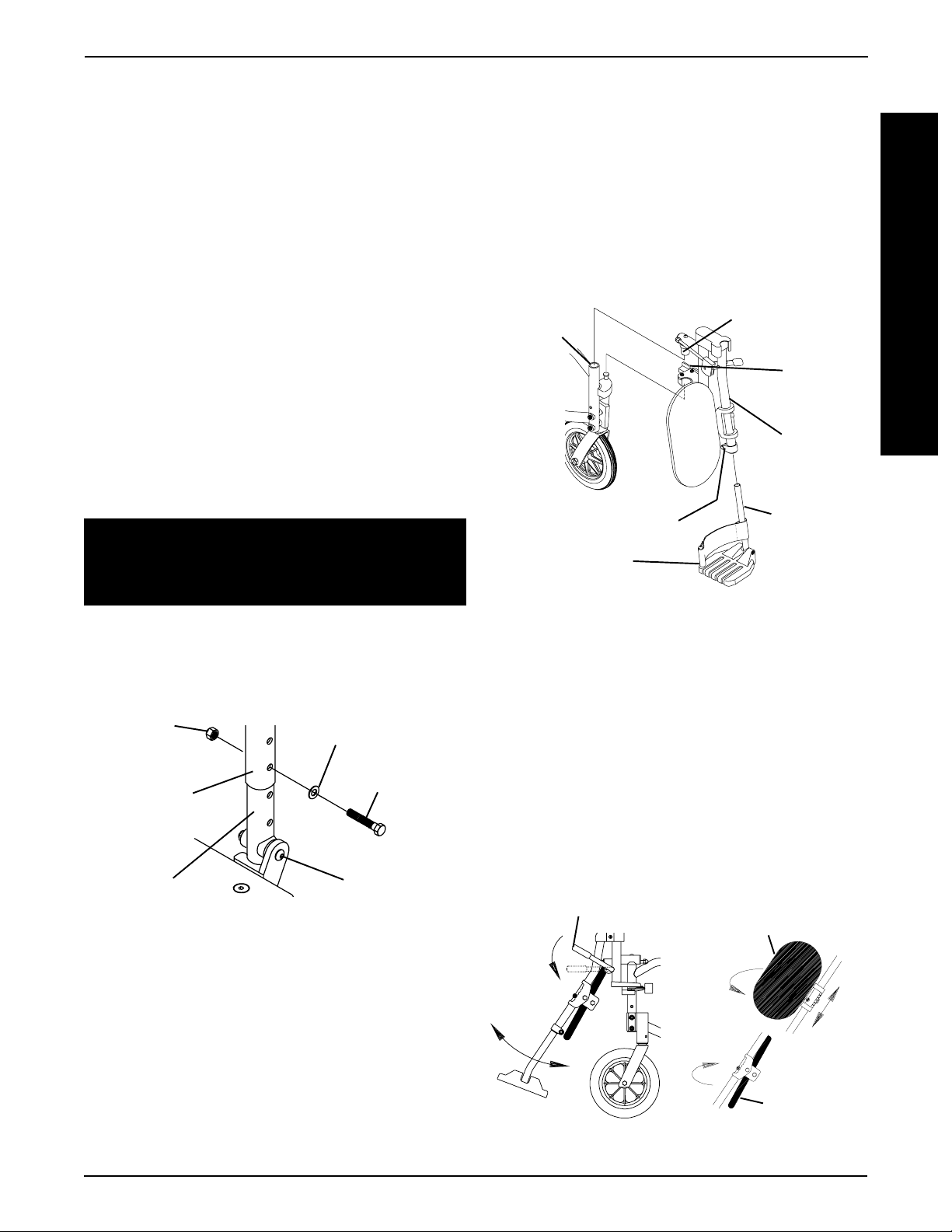
INSTALLING FOOTRESTS (FIGURE 1)
1. Turn the footrest to the side (open footplate is
perpendicular to wheelchair).
2. Insert mounting pin into mounting tube.
3. Push the footrest towards the inside of the
wheelchair until it locks into place.
NOTE: The footplate will be on the inside of the
wheelchair when locked in place.
4. Repeat this procedure for the opposite footrest.
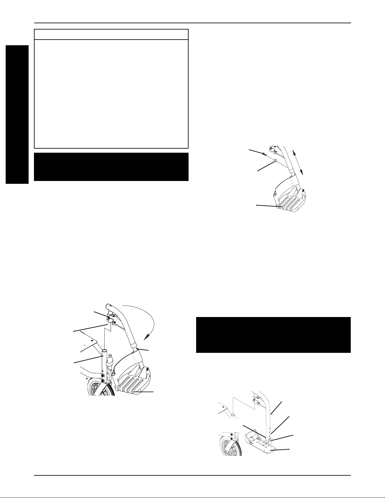
Pivot Slide T ube Height Adjustment (FIGURE 2)
1. Remove any accessories that are attached to the
footrests.
2. Remove the hex screw and coved washer and position the footrest assembly to the desired height.
3. Lineup the mounting hole in the footrest support,
reinsert the hex screw and coved washer and securely tighten.
4. Repeat STEPS 1-3 for the other footrest.
5. Reinstall any accessories that are attached to the
footrest.
Hex Screw
Coved Washer
Footrest
FIGURE 2 - PIVOT SLIDE TUBE HEIGHT
ADJUSTMENT
Footplate Height Adjustment (70o MFX and 90
Footrests Only) (FIGURE 3)
1. Remove any accessories that are attached to the
footrests.
o
5. To release the footrest, push the footrest release
lever inward, rotate footrest outward.
Mounting Pin
Footrest
Release
Lever
Footrest
Mounting
Tube
Footplate
NOTE: All swingaway style footrests are installed the same
way. Only one (1) style of footrest is shown for clarity .
FIGURE 1 - INSTALLING FOOTRESTS
ADJUSTING FOOTREST HEIGHT
NOTE: Release the footrest locking mechanism and
lift the mounting pin out of the mounting tube. Lay
the assembly on a flat surface to simplify procedure.
2. Remove the socket bolt, coved washer and
locknut that secure the footplate to the footrest
support.
3. Reposition the footplate to the desire height.
WARNING
DO NOT overtighten. Footrest must be able to
rotate upward from the horizontal to vertical
position.
4. Reinstall the socket bolt through the mounting
holes of the footplate and footrest support.
5. Secure the footplate to the footrest support with
the coved washer and locknut.
Footrest Support
Height Adjustment
Locknut
FIGURE 3 - FOOTPLA TE HEIGHT ADJUSTMENT
O
(70
MFX AND 90O FOOTRESTS ONLY)
Holes
Socket Bolt
Footplate
16
Page 17
FRONT RIGGINGS PROCEDURE 1
INST ALLING 3-INCH EXTENSION (FIGURE 4)
NOTE: Make sure to note position of hardware
before disassembly of the footrest.
NOTE: If using ANY type of extension with the
ADJUSTABLE ANGLE FOOTPLATE, refer to
INSTALLING/ADJUSTING ADJUSTABLE ANGLE
FLIP-UP FOOTPLATES in this section of the
manual.
1. Remove any accessories that are attached to the
footrests.
2. Remove the socket bolt, coved washer and locknut that secure the footplate to the footrest support.
3. Insert the 3-inch extension into the footrest support and align the mounting holes.
4. Secure the 3-inch extension to the footrest support with new hex bolt, washer and locknut.
5. Position the footplate at the desired height.
WARNING
DO NOT overtighten. Footrest must be able to
rotate upward from the horizontal to vertical position.
6. Reinstall the socket bolt through the mounting
holes of the footplate and footrest support.
7. Secure the footplate to the footrest support with
the coved washer and locknut.
Locknut
Washer
NOTE: The footplate will be on the inside of the
wheelchair when locked in place.
4. Repeat STEPS 1-3 for the opposite legrest.
5. After seated in wheelchair, adjust footrest to correct height by loosening nut and sliding the pivot
tube up or down until desired height is obtained.
6. To release the legrest, push the legrest release
handle toward the inside of the wheelchair and
swing the legrest to the outside of the wheelchair.
Mounting
Tube
Bolt and Nut
Footplate
FIGURE 5 - INST ALLING ELEVATING LEGRESTS
Mounting Pin
Legrest
Release
Handle
Legrest
Support
Pivot Tube
RAISING/LOWERING ELEV ATING LEGRESTS
AND/OR ADJUSTING CALFP ADS (FIGURE 6)
Raising/Lowering Elevating Legrests
1. Perform one (1) of the following:
F
R
O
N
T
R
I
G
G
I
N
G
S
Footrest
Support
3-inch
Extension
FIGURE 4 - INSTALLING 3-INCH EXTENSION
Hex Bolt
Socket Bolt,
Coved Washer
and Locknut
INST ALLING ELEVA TING LEGRESTS
(FIGURE 5)
1. Insert the pivot tube into the legrest support and
secure it with the bolt and nut.
2. Place legrest on the outside of the wheelchair and
insert the mounting pin into the mounting tube.
3. Rotate legrest toward the inside of the wheelchair
until it locks in place.
RAISING - Pull back on the release lever un-
til the leg is at the desired height.
LOWERING - Support leg with one (1) hand and
push release lever downward with
other hand.
Release Lever
FIGURE 6 - RAISING/LOWERING ELEV ATING
LEGRESTS AND/OR ADJUSTING CALFP ADS
17
Calfpad Rotated For
Height Adjustment
Calfpad
Page 18
PROCEDURE 1 FRONT RIGGINGS
F
R
O
N
T
R
G
G
N
G
S
Adjusting Calfpads
1. To adjust the calfpad, turn pad towards the
outside of the wheelchair.
2. Slide the calfpad up or down until the desired
position is obtained.
3. To secure the calfpad, turn the calfpad towards the
inside of the wheelchair.
INST ALLING/ADJUSTING ADJUSTABLE
I
ANGLE FLIP-UP FOOTPLA TES
WARNING
I
When determining the angle of the footplates, make
sure the rear of the footplates do not interfere with
the movement of the front casters.
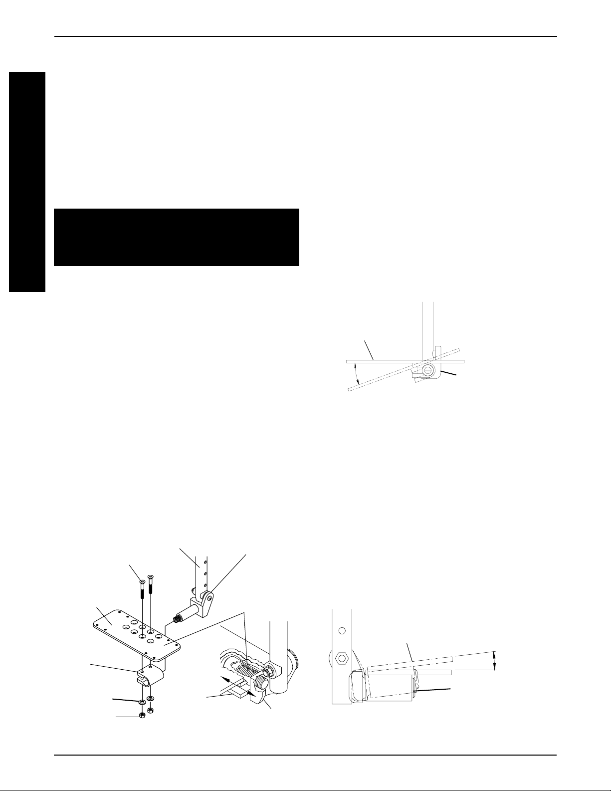
Installing Adjustable Angle Flip-up Footplates
(FIGURE 7)
1. Slide the half clamp over the footplate hinge.
2. Loosely tighten the two (2) flat bolts, washers and
locknuts that secure the footplate to the half clamp.
2. Move the adjustable angle flip-up footplate to one
(1) of four (4) mounting positions.
3. Retighten the two (2) flat bolts, washers and locknuts.
NOTE: The settings for positioning the adjustable
angle flip-up footplates on the half-clamps may vary
for each footplate.
Adjustable Angle Flip-up Footplate Angle
Adjustment (FIGURES 7 AND 8)
1. Loosen, but do not remove the two (2) flat bolts and
locknuts that secure the adjustable angle flip-up
footplate to the footplate hinge.
2. Position the adjustable angle flip-up footplate to the
necessary angle to accommodate the user.
3. Retighten the two (2) flat bolts and locknuts.
Adjustable
Angle Flip-up
Footplate
Looking From
Inside Towards
the Outside of the
Wheelchair.
3. If necessary, adjust the footplates to the necessary
angle and depth for the user. Refer to the following
sections of this procedure.
Adjustable Angle Flip-up Footplate Depth
Adjustment (FIGURE 7)
1. Remove the two (2) flat bolts, washers and locknuts
that secure the adjustable angle flip-up footplate to
the footplate hinge.
NOTE: Observe the angle of the articulating footplate
for reinstallation.
90o Footrest Support
Flat Bolts
Adjustable
Angle Flip-Up
Footplate
Footplate Hinge
Nylon
Adjustment
Screw
Footplate Hinge
FIGURE 8 - ADJUSTABLE ANGLE FLIP-UP
FOOTPLA TE ANGLE ADJUSTMENT
Adjustable Angle Flip-up Footplate
Perpendicular and/or Inversion/Eversion
Adjustment (FIGURES 7 AND 9)
NOTE: It is not necessary to remove the footplate
to perform this adjustment.
1. Insert a flathead screwdriver through the half
clamp on the adjustable angle flip-up footplate.
2. Slowly turn the nylon adjustment screw in or out
until the adjustable angle flip-up footplate is perpendicular to the footrest assembly or the desired
inversion/eversion is obtained.
Adjustable
Angle Flip-Up
Footplate
Looking From the Front
Towards the Rear of
the Wheelchair
Half
Clamp
Washers
Locknuts
FIGURE 7 - INST ALLING ADJUSTABLE ANGLE
FLIP-UP FOOTPLATES
Half
Clamp
Footplate Hinge
Half Clamp
FIGURE 9 - ADJUSTABLE ANGLE FLIP-UP
FOOTPLA TE PERPENDICULAR AND/OR
INVERSION/EVERSION ADJUSTMENT
18
Page 19
FRONT RIGGINGS PROCEDURE 1
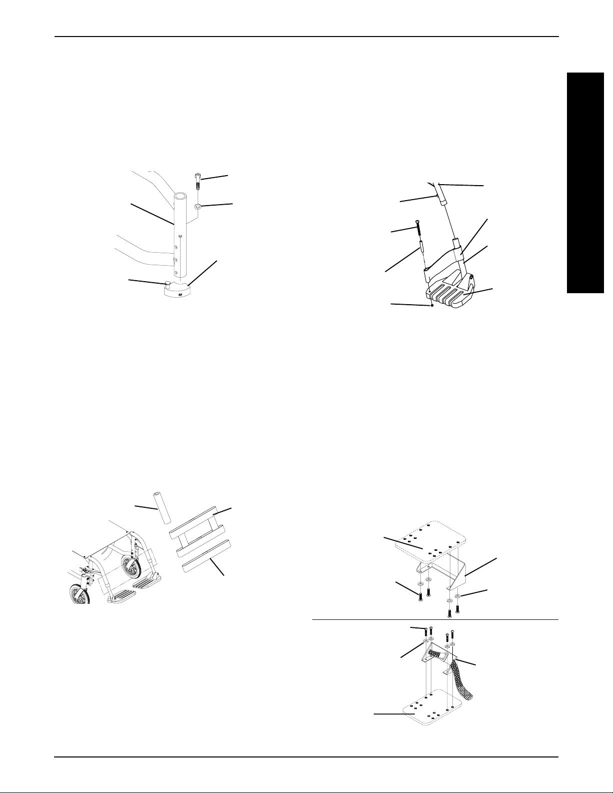
REPLACING SECTOR BLOCK (FIGURE 10)
1. Remove the hex screw and washer that secure
the existing sector block to the wheelchair frame.
2. Position the new sector block on the wheelchair
frame. Make sure the locking pin is facing UP.
3. Secure the new sector block to the wheelchair
frame with the existing hex screw and washer.
Hex Screw
Wheelchair
Frame
Locking Pin
FIGURE 10 - REPLACING SECTOR BLOCK
Washer
Sector Block
OPTIONAL FOOTREST ACCESSORIES
3. Remove the phillips bolt and locknut that secure the
heel loop to the footplate.
4. Slide heel loop over the pivot tube.
5. Replace heel loop.
6. Reverse STEPS 1-5 to install the new heel loop.
NOTE: When securing the heel loop to the footrest
assembly, tighten the phillips bolt and locknut until
the spacer is secure.
Hex Screw/
Coved Washer
Phillips Bolt
Spacer
Locknut
FIGURE 12 - REPLACING HEEL LOOPS -
ALUMINUM OR COMPOSITE FOOTPLA TES
Footrest
Support
Heel Loop
Pivot Tube
Footplate
F
R
O
N
T
R
I
G
G
I
N
G
S
Impact Guards/Calf Strap/H-Calf Strap
(FIGURE 11)
NOTE: Impact Guards are Standard Equipment on
Model ST Footrests. No assembly is required.
1. Remove impact guard/calf strap from packaged container.
2. Secure the impact guards to the footrest frame.
3. Secure the calf strap around the footrest frame (with
the impact guards attached).
Impact Guard
FIGURE 11 - IMPACT GUARDS/CALF STRAP/
H-CALF STRAP
H-Calf Strap
Calf Strap
FLIP-UP FOOTPLA TES (FIGURE 13).
1. Remove the four (4) phillips screws and washers
that secure the heel loop to the footplate.
2. Remove the existing heel loop from the footplate.
3. Position the new heel loop UNDER the footplate.
NOTE: If the heel loop is equipped with an ankle strap,
position the heel loop on TOP of the footplate.
4. Line up mounting holes in footplate and heel loop.
5. Secure the new heel loop to the footplate with the
four (4) existing phillips screws and washers.
Footplate
Heel Loop
Phillips Screws
Washers
Phillips Screws
Replacing Heel Loops
ALUMINUM OR COMPOSITE FOOTPLA TES
(FIGURE 12).
1. Remove the hex screw and coved washer that secure the pivot tube and footplate to footrest support.
2. Remove the pivot tube and footplate from the footrest support.
Washers
Heel Loop with
Ankle Strap
Footplate
FIGURE 13 - REPLACING HEEL LOOPS -
FLIP-UP FOOTPLATES
19
Page 20
ARMSPROCEDURE 2
A
R
M
S
This Procedure Includes the Following:
Installing the "T" Arm Sockets
Installing/Removing the "T" Arms
Adjusting the "T" Arms
Adjusting the Transfer Assists and/or Side Guards -
"T" Arms
Replacing the Locking Lever - "T" Arms
Using/Installing/Height Adjustment/Corresponding
Adjustment to Back Angle - Cantilever Arms
Replacing/Repositioning the Locking
Mechanism in the Cantilever Arm
Arm Pad Depth Adjustment/Replacement -
Cantilever Arms
Installing Fabric Clothing Guards
Installing Rigid Side Guards
Adjusting Conventional Arm Height, Removing or
Replacing Conventional Arms
Replacing Armrest Pads
Repositioning the Conventional Arms
WARNING
NEVER try to lift or tip the wheelchair by cantilever
arms or "T" arms, serious injury can occur.
After adjustments and before use, make sure all attaching hardware is securely tightened.
INST ALLING THE "T" ARM SOCKETS
(FIGURE 1)
1. Remove the rear wheels from the wheelchair. If necessary, refer to the owner's manual supplied with the
wheelchair.
NOTE: If desired, locking pins can be installed to secure the "T" arm brackets to the wheelchair frame,
as shown in FIGURE 1.
6. Repeat STEPS 2-6 for the opposite side of the wheel-
chair.
7. Install the "T" arms into the "T" arm sockets. Refer to
INSTALLING/REMOVING THE "T" ARMS in this
section of the manual.
Hex Screws
Optional Locking Pins
Wheelchair Frame
Washers
"T" Arm Clamp
"T" Arm Socket
FIGURE 1 - INST ALLING THE "T" ARM SOCKETS
INST ALLING/REMOVING THE "T" ARMS
(FIGURE 2)
Installing
1. Position the "T" arm over the "T" arm socket on
the wheelchair frame.
NOTE: Make sure the locking lever is towards
the front of the wheelchair.
2. Position the "T" arm socket and "T" arm clamp on
the wheelchair frame as shown in FIGURE 1.
NOTE: The "T" arm socket must be positioned on
the outside of the wheelchair frame.
3. Install the hex screws and washers through the "T"
arm clamp and "T" arm socket and loosely tighten.
4. Tighten the hex screws and washers that secure the
"T" arm mounting socket to the wheelchair frame in
the following sequence:
A. Middle hex screw and washer.
B. The two (2) outside hex screws and washers.
5. Continue to repeat STEP 5 until the hex bolts are
torqued to 156-inch pounds.
NOTE: Make sure the hex bolts are torqued to 156inch pounds, otherwise the "T" arm sockets will be
capable of rotating around the wheelchair frame.
2. Slide the "T" arm into the "T" arm socket until the
locking lever is in the slot in the "T" arm socket
and an audible "click" is heard.
3. Pull up on the "T" arm to make sure the "T" arm is
locked in place.
NOTE: If the "T" arm does not slide in the "T"
arm socket as desired, adjust the "T" arm
socket. Refer to ADJUSTING THE "T" ARMS in
this section of the manual.
4. Adjust the "T" arm for desired height, width and
depth, if necessary. Refer to ADJUSTING THE
"T" ARMS in this section of the manual.
5. Repeat STEPS 1-4 for the opposite side of the
wheelchair.
20
Page 21
PROCEDURE 2ARMS
Removing
1. Press in on the locking lever and lift the "T" arm straight
up and out of the "T" arm socket.
NOTE: If the "T" arm does not slide up and down in
the "T" arm socket as desired, adjust the "T" arm
socket. Refer to ADJUSTING THE "T" ARMS in this
section of the manual.
2. Repeat STEP 2 for the opposite side of the wheelchair.
"T" Arm
Wheelchair
Frame
Locking Lever
(Towards the
"T" Arm
Socket
front of the
wheelchair.)
Slot
FIGURE 2 - INST ALLING/REMOVING THE "T"
ARMS
B. Loosen - Loosening the set screws on the out-
side "T" arm post will make it easier to move
the inside "T" arm post up and down.
3. Lock the "T" arm by flipping the "T" arm release
lever towards the front of the wheelchair.
"T" Arm Release
Lever - Unlocked
Position
Set
Screws
Inside "T"
Arm Post
Outside "T"
Arm Post
"T" Arm Release Lever -
Locked Position
FIGURE 3 - ADJUSTING THE "T" ARMS -
HEIGHT
Width (FIGURE 4)
1. Remove the two (2) phillips screws that secure the
arm pad to the arm tube.
2. Turn the arm pad around and reposition the arm
pad on the arm tube.
3. Re-secure the arm pad to the arm tube with the two
(2) phillips screws.
A
R
M
S
ADJUSTING THE "T" ARMS
Height (FIGURE 3)
1. Unlock the "T" arm by flipping the "T" arm release
lever towards the inside of the wheelchair.
NOTE: If necessary, Pull out on the "T" arm release lever and rotate 180
towards the outside of the wheelchair.
2. Slide the "T" arm to one (1) of:
A. Low Height "T" Arms - Nine (9) positions.
B. High Height "T" Arms - Seven (7) positions.
NOTE: If the inside "T" arm post does not slide up
and down in the outside "T" arm post as desired,
perform one (1) of the following:
A. Tighten - Tightening the set screws on the out-
side "T" arm post will make it harder to move
the inside "T" arm post up and down.
o
so it can be flipped
4. Repeat for the opposite side, if necessary.
Arm Pad
Arm Tube
Phillips
Phillips Screw
Screw
FIGURE 4 - ADJUSTING THE "T" ARMS -
WIDTH
Depth (FIGURE 5)
1. Remove the two (2) phillips screws that secure the
arm pad to the arm tube.
2. Remove the two (2) socket screws that secure the
arm tube to the "T" arm post.
21
Page 22

ARMSPROCEDURE 2
A
R
M
S
3. Reposition the arm tube on the "T" arm post:
A. Desk Length Arms - to one (1) of three (3) posi-
tions depending on the desired arm pad depth.
B. Full Length Arms - to one (1) of five (5) posi-
tions depending on the desired arm pad depth.
NOTE: Additional positions are obtainable by turning the arm tube 180
4. Re-secure the arm tube to the "T" arm post with the
two (2) socket screws.
5. Reattach the arm pad to the arm tube with the two
(2) phillips screws.
6. Repeat for the opposite side, if necessary.
o
.
Arm Pad
Socket
Screws
Arm Tube
NOTE: If
necessary, turn
Phillips
Screw
arm tube 180
to obtain two
(2) positions.
"T" Arm
Post
FIGURE 5 - ADJUSTING THE "T" ARMS -
"T" Arm Sockets (FIGURE 6)
Phillips Screw
DEPTH
6. Squeeze the "T" arm socket together until the socket
is flush with the "T" arm.
7. While holding the "T" arm socket together, tighten
the four (4) hex screws and washers securely.
8. Press in on the locking lever and lift the "T" arm straight
up and out of the "T" arm socket.
9. Repeat STEPS 5-7, if necessary until the "T" arm
slides in the "T" arm socket as desired.
10. Reinstall the "T" arm socket onto the wheelchair.
Refer to INST ALLING THE "T" ARM SOCKETS in
this section of the manual.
Hex Screws
Optional Locking Pins
Wheelchair Frame
Washers
"T" Arm Clamp
"T" Arm Socket
o
"T" Arm
1. Remove the rear wheels from the wheelchair. If necessary, refer to the owner's manual supplied with the
wheelchair.
2. Remove the three (3) hex screws and washers that
secure the "T" arm socket and "T" arm clamp to the
wheelchair frame and remove the "T" arm socket
from the wheelchair.
3. If equipped with optional locking pins, remove the
locking pins that secure the "T" arm socket to the
wheelchair frame.
4. Loosen, but do not remove the four (4) hex screws
and washers that secure the "T" arm socket together.
NOTE: The "T" arm socket will disassemble if the
four (4) hex screws and washers are removed.
5. Slide the "T" arm into the "T" arm socket until the lock
lever is in the slot in the "T" arm socket and an audible "click" is heard.
Hex Screws
and Washers
"T" Arm
Socket
FIGURE 6 - ADJUSTING THE "T" ARMS - "T"
ARM SOCKETS
Hex Screws
and Washers
ADJUSTING THE TRANSFER ASSISTS AND/
OR SIDE GUARDS - "T" ARMS (FIGURE 7)
1. Remove the "T" arm from the wheelchair. Refer
to INSTALLING/REMOVING THE "T" ARMS in
this section of the manual.
2. Remove the bottom socket screw that secures
the side guard to the bottom clamp.
22
Page 23

ARMS PROCEDURE 2
3. Move the bottom clamp to one (1) of three (3)
mounting holes in the side guard.
NOTE: The middle mounting hole is the standard mounting position for rigid wheelchairs.
NOTE: The bottom mounting hole is the standard mounting position for folding wheelchairs.
NOTE: The top mounting hole is an optional
mounting position for folding or rigid wheelchairs.
4. Re-secure the side guard to the bottom clamp
with the socket screw.
5. Install the "T" arm onto the wheelchair. Refer to
INST ALLING/REMOVING THE "T" ARMS in this
section of the manual.
Top
Middle
Bottom
Side
Guard
"T" Arm
Transfer
Assist
3. Remove the existing locking lever and spring from
the bottom bracket.
NOTE: Inspect the spring and replace if necessary .
4. Position the spring on the bottom bracket as shown
in FIGURE 8.
5. Position the new locking lever onto the spring and
the bottom bracket.
NOTE: Make sure the two (2) extended ends of the
spring are inside the notch in the locking lever.
6. Line up the mounting holes in the new locking lever,
spring and bottom bracket.
WARNING
DO NOT over tighten the locknut that secures the
locking lever to the bottom bracket. Over tightening
this locknut will prevent the locking lever from operating properly , possibly causing injury .
7. Install the phillips bolt and tighten securely with the
locknut.
8. Install the "T" arm onto the wheelchair. Refer to IN-
ST ALLING/REMOVING THE "T" ARMS in this section of the manual.
Extended Ends
A
R
M
S
Socket
Screws
Bottom Clamp
FIGURE 7 - ADJUSTING THE TRANSFER
ASSISTS AND/OR SIDE GUARDS - "T" ARMS
REPLACING THE LOCKING LEVER - "T"
ARMS (FIGURE 8)
1. Remove the "T" arm from the wheelchair. Refer to
INSTALLING/REMOVING THE "T" ARMS in this
section of the manual.
2. Remove the phillips bolt and locknut that secure the
existing locking lever to the bottom bracket.
CAUTION
The locking lever is spring loaded. Place your
free hand over the locking lever to prevent the
parts from springing off of the bottom bracket.
Spring
Bottom
Bracket
Phillips Bolt
FIGURE 8 - REPLACING THE LOCKING LEVER
- "T" ARMS
Notch
Locknut
Locking
Lever
23
Page 24

ARMSPROCEDURE 2
A
R
M
S
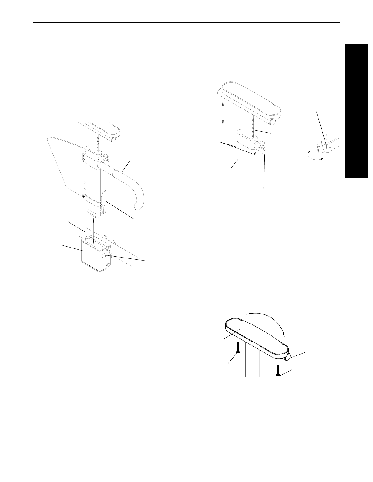
USING/INSTALLING/HEIGHT
ADJUSTMENT/CORRESPONDING ARM
ADJUSTMENT TO BACK ANGLE CANTILEVER ARMS
NOTE: The cantilever arms are designed for use
with the fixed height back canes only.
Using (FIGURE 9)
1. Pull the actuator of the locking mechanism
towards the front of the wheelchair.
2. While holding the actuator of the locking mechanism, pull up on the cantilever arm.
NOTE: If necessary, the locking mechanism in the
cantilever arm can be repositioned so the cantilever
arm will open down instead of up. Refer to REPLACING/REPOSITIONING THE LOCKING MECHANISM IN
THE CANTILEVER ARM in this section of the manual.
3. To lock the cantilever arm, push down until there
is an audible click.
4. Pull up on the cantilever arm to make sure it is
locked in place.
2. Slide the bottom hex bolt (w/coved washer) through
the adjustment plate and back cane.
3. Securely tighten the cantilever arm to the wheelchair
with two (2) locknuts and washers.
4. Adjust the angle of the cantilever arm, if necessary.
Refer to CORRESPONDING ARM ADJUSTMENT
TO BACK ANGLE in this section of the manual.
Corresponding Arm Adjustment to Back Angle
(FIGURES 10 and 11)
NOTE: This adjustment is recommended if the back
angle has been changed to keep arm parallel to the
ground/floor.
1. Flip the cantilever arm up and out of the way.
2. Remove the locknut that secures the locking pin to
the adjustment plate (FIGURE 10).
Adjustment Plate
Locking Pin
Locknut
Installing/Height Adjustment (FIGURE 9)
NOTE: When removing the locknuts and washers
from the cantilever arm assembly, leave the top
hex bolt, coved washers and spacer (between adjustment plate and cantilever arm) in place.
1. Slide the partially assembled cantilever arm
assembly w/mounting hardware through the back
cane. Make sure the adjustment plate is towards
the inside of the wheelchair.
NOTE: This includes top hex bolt, coved washers
and spacer (between adjustment plate and cantilever arm).
Coved Washers
Adjustment Plate
Back Cane
Spacer
Actuator
Locknuts
Washers
Washer
FIGURE 10 - ADJUSTING THE CANTILEVER ARMS
80
Back Plate
Arm Plate
85
Back Plate
Arm Plate
90
Back Plate
O
Back Plate
Arm Plate
O
Back Plate
Arm Plate
O
105O AND 110
Back Plate
95
100
O
O
O
Top Hex Bolt
and Coved Washer
Bottom Hex Bolt
FIGURE 9- USING/INST ALLING/HEIGHT
ADJUSTMENT - CANTILEVER ARMS
Cantilever Arm
Arm Plate
24
Arm Plate
FIGURE 11 - CORRESPONDING ARM
ADJUSTMENT TO BACK ANGLE -
CANTILEVER ARMS
Page 25

ARMS PROCEDURE 2
3. Refer to FIGURE 6 to determine the mounting hole
in the adjustment plate that will be used to correspond to the back angle.
o
NOTE: Back angles of 105
arm adjustment plate mounting holes.
4. Securely tighten the locking pin and washer to the
adjustment plate with a locknut.
5. Repeat STEPS 1-4 for the opposite side, if necessary.
and 110o will use the same
REPLACING/REPOSITIONING THE LOCKING
MECHANISM IN THE CANTILEVER ARM
(FIGURE 12)
1. Move the cantilever arm up and out of the way.
2. Remove the actuator from the locking mechanism.
CAUTION
The locking mechanism is spring loaded. Place your
free hand over the locking mechanism to prevent
the parts from springing out of the cantilever arm.
ARM P AD DEPTH ADJUSTMENT/
REPLACEMENT - CANTILEVER ARMS
(FIGURE 13)
Adjustment
1. Remove the phillips screw from the rear of the arm-
rest pad and self-taping screw if FULL LENGTH ARM
P ADS.
2. Depending on the desired arm pad depth, reposition the cantilever slide tube to one (1) of five (5)
positions for DESK LENGTH ARM PADS and into
the FIRST adjustment hole for the FULL LENGTH
ARM P ADS.
3. Reattach the arm pad/cantilever slide tube to the
arm tube with existing hardware.
4. Repeat for the opposite side, if necessary.
Replacement
1. Remove the phillips screws from the armrest pad.
2. Replace with NEW armrest pad.
A
R
M
S
3. Slowly let the locking mechanism and spring slide
out of the cantilever arm.
NOTE: Inspect the spring and replace if necessary .
4. Slide the new locking mechanism and spring into
the cantilever arm.
5. Position the angled portion of the locking mechanism in one (1) of two (2) ways:
Angled Portion Facing Up - Arm will flip UP
Angled Portion Facing Down - Arm will flip DOWN
6. Use Loctite 242 and securely tighten the actuator
into the locking mechanism.
7. To lock the cantilever arm, push down until there is
an audible click.
8. Pull up on the cantilever arm to make sure it is locked
in place.
Angled Portion of
Locking Mechanism
Locking
Mechanism
Cantilever Arm
Spring
3. Secure with existing hardware.
Desk Length
Arm Pads
Phillips Screw
(Rear of Armrest
Pad)
NOTE: This Phillips Screw only needs to be removed when Armrest Pad is replaced.
Cantilever Slide Tube
Full Length
Arm Pads
Phillips Screw
(Rear of Armrest
Pad)
Cantilever Arm
Self-Tapping Screw
NOTE: Only these Adjustment Holes can be used.
Cantilever Slide Tube
Actuator
(Apply Loctite 242)
FIGURE 12 - REPLACING/REPOSITIONING THE
LOCKING MECHANISM IN THE FLIP-UP HALF ARM
NOTE: This Phillips Screw only needs to be removed when Armrest Pad is replaced.
FIGURE 13 - ARM P AD DEPTH ADJUSTMENT/
REPLACEMENT - CANTILEVER ARMS
25
Page 26

PROCEDURE 2 ARMS
A
R
M
S
INST ALLING F ABRIC CLOTHING GUARDS
(FIGURE 14)
1. Remove the seat cushion, if necessary.
2. Secure the fastening straps of the fabric clothing protectors to the seat upholstery.
3. Reinstall the seat cushion, if necessary.
4. Remove the two (2) phillips screws that secure the
back upholstery to the back canes.
5. Position the D-rings on the mounting holes in the
back canes.
6. Reinstall the two (2) phillips screws and securely
tighten.
7. Run the nylon cord evenly through the two (2) Drings.
8. Run the nylon cord through the cord lock.
9. Push star wheel into cord lock to hold the nylon cord
in place.
10. Tie a knot in the nylon cord and cut the excess, if
desired.
Fabric Clothing
Guard
5. Determine the necessary position for the rigid side
guard.
6. Securely tighten the two (2) half clamps together with
the socket screw.
Washer
Unthreaded Half Clamp
Rigid
Side
Guard
Threaded Half Clamp
FIGURE 15 - INST ALLING RIGID SIDE GUARDS
Socket Screw
Wheelchair Frame
ADJUSTING CONVENTIONAL ARM HEIGHT,
REMOVING OR REPLACING
CONVENTIONAL ARMS (FIGURE 16)
WARNING
Make sure the armrest release levers are secured
before using the wheelchair.
Adjusting Conventional Arm Height
Fastening Strap
Seat Upholstery
Cord Lock
Phillips Screw,
D-ring
Nylon Cord
FIGURE 14 - INST ALLING FABRIC CLOTHING
GUARDS
Phillips
Screw,
D-ring
Star
Wheel
INST ALLING RIGID SIDE GUARDS (FIGURE 15)
1. Position the unthreaded half clamp on the INSIDE
of the wheelchair frame.
2. Position the threaded half clamp on the OUTSIDE
of the wheelchair frame.
3. Install the washer and socket screw through the two
(2) half clamps and loosely tighten.
4. Slide the rigid side guard into the slot on the threaded
half clamp.
1. Unlock the conventional arm by flipping the armrest release lever on the top front of the armrest
to the UP (HORIZONTAL) position.
2. Adjust conventional arm to desired height.
NOTE: Height adjustment levers MUST be in the
unlocked position when placing upper arm into
the arm assembly.
3. Lock the conventional arm by pressing the release
lever into the DOWN (VERTICAL) position when
the desired armrest height is achieved.
Removing Conventional Arms
1. Unlock the conventional by turning the armrest
release lever located on the side rail to the unlocked position.
2. Remove the conventional arm from the wheelchair.
Replacing Conventional Arms
NOTE: Armrest release levers MUST be in the un-
locked position when placing armrests into the arm
sockets.
1. Position the conventional arm in the arm sockets
and lock the conventional arm by turning the armrest release levers into the locked position.
26
Page 27

ARMS PROCEDURE 2
Height
Adjustment
Lever
FIGURE 16 - ADJUSTING CONVENTIONAL
ARM HEIGHT, REMOVING OR REPLACING
CONVENTIONAL ARMS
Locked (DOWN -
VERTICAL)
Unlocked (UPHORIZONTAL)
Armrest Release
Lever
REPLACING ARMREST P ADS (FIGURE 17)
1. Remove the phillips screws that secure the armrest pad to the armrest assembly.
2. Replace armrest pad and securely tighten with
the existing phillips screws.
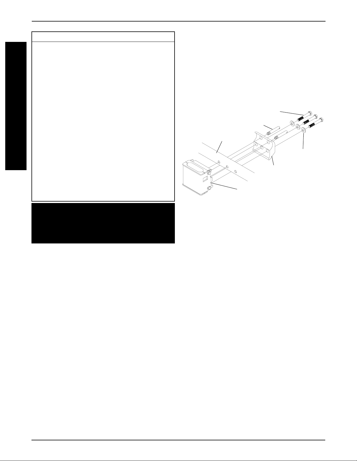
3. Move the rear arm socket, nylon shim and rear arm
socket mount to the position determined in STEP 1.
4. Reinstall the rear arm socket, nylon shim and rear
arm socket mount onto the wheelchair with the hex
bolt, washer and locknut. Refer to FIGURE 13 for
correct orientation.
5. Repeat STEPS 1-4 for the opposite side of the wheelchair.
Rear Arm Socket
Hex Bolt
Nylon
Shim
Rear Arm
Wheelchair
Locknut
CONVENTIONAL ARMS - REAR ARM SOCKETS
Front Arm Sockets (FIGURE 19)
Washer
FIGURE 18 - REPOSITIONING THE
Frame
Socket
Mount
A
R
M
S
Armrest Pad
Phillips Screws
Armrest Assembly
FIGURE 17 - REPLACING ARMREST P ADS
REPOSITIONING THE CONVENTIONAL ARMS
NOTE: Conventional arms can only be repositioned
on medium and long frame wheelchairs. There is only
one (1) position for conventional arms on short frame
wheelchairs.
Rear Arm Sockets (FIGURE 18)
1. Determine the necessary rear arm socket position
for the necessary seat depth. Refer to CHANGING
SEA T DEPTHS in PROCEDURE 10 of this manual.
1. Determine the necessary front arm socket and seat
guide position for the necessary seat depth. Refer
to CHANGING SEA T DEPTHS in PROCEDURE 10
of this manual.
2. Remove the socket bolts and locknuts that secure
the front arm socket and seat guide to the wheelchair.
3. Move the front arm socket and seat guide to the
position determined in STEP 1.
4. Resecure the front arm socket and seat guide to the
wheelchair with the socket bolts and locknuts.
5. Repeat STEPS 1-4 for the opposite side of the wheelchair.
Socket Bolt
Socket Bolt
Front Arm
Socket
Seat Guide
Wheelchair
Locknut
Frame
2. Remove the hex bolt, washer and locknut that secure the rear arm socket, nylon shim and rear arm
socket mount to the wheelchair frame.
FIGURE 19 - REPOSITIONING THE
CONVENTIONAL ARMS - FRONT ARM SOCKETS
27
Page 28

PROCEDURE 3 BACK
B
A
C
K
This Procedure Includes the Following:
Folding/Unfolding the Back
Replacing Back Upholstery
Adjusting the Back Height
Replacing the Locking Mechanism in
the Back Cane
Changing the Back Angle
Repositioning the Back (Changing Seat Depth)
Repositioning Back for 2 or 3-Inch Seat
Cushion - Recliners Only
Replacing Folding Push Handle - Recliners
Only
Installing and Removing a Seating System
WARNING
After adjustments and before use, make sure all
attaching hardware is securely tightened.
REPLACING BACK UPHOLSTERY
NOTE: If the back upholstery HEIGHT is being
changed, the back canes may also have to be
changed. Refer to ADJUSTING THE BACK HEIGHT
in this section of the manual.
Standard Back Upholstery (FIGURE 2)
1. Remove the two (2) phillips screws and washers that
secure the existing back upholstery to the back canes.
2. Remove the hex screw and locknut that secure one
(1) back cane to the wheelchair frame.
NOTE: It is necessary to remove only one (1) back
cane to replace the back upholstery .
3. Pull the loose back cane out of the existing back
upholstery.
4. Pull the existing back upholstery up and over the
mounted back cane.
5. Install the new back upholstery over the mounted
back cane.
FOLDING/UNFOLDING THE BACK (FIGURE 1)
WARNING
Make sure the back is locked securely BEFORE
using the wheelchair - otherwise injury can occur.
NOTE: The following procedure is for non-recliner
wheelchairs only .
1. Pull the actuator of the locking mechanism up towards the top of the wheelchair.
2. While holding the actuator of the locking mechanism,
push the back down.
NOTE: The back can be pushed towards the anterior (front) or the posterior (rear) of the wheelchair
depending on need.
3. To lock the back into place, pull up until there is an
audible click.
4. Push on the back to make sure it is locked in place.
Back Cane
6. Slide the loose back cane through the new back
upholstery.
7. Secure the back cane to the wheelchair frame with
the hex screw and locknut.
8. Secure the new back upholstery to the back canes
with the existing phillips screws and washers.
Back Upholstery
Washers
Phillips
Screws
Remove Back Cane
FIGURE 2 - REPLACING ST ANDARD BACK
UPHOLSTERY
Actuator
FIGURE 1 - FOLDING/UNFOLDING THE BACK
Adjustable Back Upholstery
INST ALLING ADJUSTABLE BACK
UPHOLSTERY (FIGURE 3).
1. Remove the existing back upholstery from the
wheelchair. Refer to REPLACING STANDARD
BACK UPHOLSTERY in this section of the
manual.
28
Page 29

PROCEDURE 3BACK
2. Slide each section (anchor loop/adjuster strap) of
the adjustable back upholstery with the grommet
hole facing the rear of the wheelchair.
3. Secure the adjustable back upholstery to the back
posts with the mounting screws.
NOTE: Clean the upholstery with warm water and
mild detergent to remove superficial soil.
WARNING
After the adjustable back upholstery has been positioned to the end-users individual needs, the fastening straps MUST be securely fastened BEFORE
applying the back upholstery cover. The adjustable
back should be checked whenever entering the
wheelchair to ensure that the fastening straps are
securely fastened.
4. Slip adjuster straps through corresponding anchor
loops and adjust the back upholstery. Secure with
the fastening straps.
5. Secure the back upholstery cover (fastening strap)
to the back of the adjustable back upholstery (fastening strap).
6. Flip the back upholstery cover over the adjustable
back upholstery and secure the fastening straps to
the front of the adjustable back upholstery.
7. Lay the front portion of the back upholstery cover on
the seat upholstery.
8. Adjust the slack in the back upholstery cover and
then secure to the seat upholstery.
Fastening Strap
Back Upholstery Cover
Fastening Strap
REPLACING ADJUSTABLE BACK UPHOLSTERY
(FIGURE 3).
1. Lift up on the existing back upholstery cover and
remove the cover from the wheelchair.
2. Remove the two (2) phillips screws and washers that
secure the existing adjustable back upholstery to the
back canes.
3. Slide each section (anchor loop/adjuster strap) of
the existing adjustable back upholstery off of the back
canes.
4. Slide each section (anchor loop/adjuster strap) of
the new adjustable back upholstery with the grommet hole facing the rear of the wheelchair.
5. Secure new adjustable back upholstery to the back
posts with the two (2) phillips screws and washers.
WARNING
After the adjustable back upholstery has been positioned to the end-users individual needs, the fastening straps MUST be securely fastened BEFORE
applying the back upholstery cover. The adjustable
back should be checked whenever entering the
wheelchair to ensure that the fastening straps are
securely fastened.
6. Slip adjuster straps through corresponding anchor
loops and adjust the back upholstery. Secure with
the fastening straps.
7. Secure the new back upholstery cover (fastening
strap) to the back of the new adjustable back upholstery (fastening strap).
8. Flip the new back upholstery cover over the new
adjustable back upholstery and secure the fastening straps to the front of the new adjustable
back upholstery.
9. Lay the front portion of the new back upholstery
cover on the seat upholstery.
B
A
C
K
Back Upholstery
Anchor Loops
Mounting Screws
Back Upholstery Adjuster Straps
FIGURE 3 - INST ALLING/REPLACING
ADJUST ABLE BACK UPHOLSTERY
Frame
10. Adjust the slack in the new back upholstery cover
and then secure to the seat upholstery.
THE ADJUST ABLE TENSION STRAPS.
The straps can be adjusted at various levels of tension to accommodate individual end-users. In a typical scenario, the bottom two (2) straps can be adjusted tightly to support and/or assist the extensor
muscles.
29
Page 30

PROCEDURE 3 BACK
The top two (2) straps would be left looser to allow the
upper body to lean back over the upholstery to fight gravity. This configuration may enable the back canes to be
lowered for a quad. In another instance, you might loosen
all of the straps and allow the end-user to sink all the way
back into the wheelchair.
B
A
C
K
Every person will be different. Let the therapist experiment with different positions and then decide. It is easy
to change.
THE BACK UPHOLSTERY COVER.
The back upholstery cover is designed for three (3)
reasons:
1. It is as a modesty cover to prevent one's posterior
from protruding out of the wheelchair.
2. It keeps the cushion from sliding out of the back of
the wheelchair.
3. It is a sacral support depending upon how far or tight
the flap is pulled under the seat cushion.
WHY USE ADJUST ABLE BACK UPHOLSTERY : A
CLINICAL DISCUSSION.
The flexible sling upholstery commonly used on wheelchairs allows the wheelchair to fold without removing rigid
components. Sling upholstery will stretch with use. Unfortunately, stretched upholstery does not support the
back well. Stretched upholstery often allows the pelvis to
drift into posterior tilt while the back assumes a kyphotic
posture.
FIGURE 4
When using a nonadjustable flat backrest, the top
portion of the upholstery will usually push the trunk
forward of the center of gravity over the pelvis. To
maintain the trunk in the upright posture, the user must
have and use the back extesor musculature, or add
tilt or recline to backrest (FIGURE 5).
FIGURE 5
When using adjustable upholstery, it is possible to
tighten the lower portion of the backrest which assists
in maintaining a neutral pelvis. The upper portion can
then be adjusted to follow the natural curvature of the
spine bringing the back over the pelvis in a position of
balance relative to the center of gravity (FIGURE 6).
With the adjustable tension backrest, the sag can be
taken out of the sling restoring the original tightness.
Adjustable tension upholstery can also provide significant improvement to the seated posture and function of
the wheelchair. By changing the tension of the strap, the
backrest can be adjusted to accommodate back postures such as kyphosis, lordosis, stabilize the pelvis and
back, and provide lateral stability.
In addition to restoring the sling to original tension, the
adjustable tension backrest can be adjusted to help
maintain the pelvis and back position, which can improve
posture balance and function.
The wheelchair backrest should be able to follow the
natural anatomical contours of the back. When viewing
a person from the side, the thoracic portion of the back
will extend posteriorly to the pelvis and buttocks (FIG-
URE 4).
FIGURE 6
The best point of control for the pelvis is near the Posterior Superior, Iliac Spine (P.S.I.S.). The upper trunk
should be relined until a balanced posture is achieved,
approximately 10 to 15 degrees (FIGURE 7).
30
Page 31

BACK PROCEDURE 3
Recliner Back Upholstery (FIGURE 10)
1. Remove the ten (10) or twelve (12) phillips screws
o
10
-15o Angle
and washers (depending on back height) that secure the back upholstery to the back canes.
P.S.I.S.
FIGURE 7
For individuals who have fixed kyphotic spine, the
backrest can be adjusted to allow for an increased
recline while providing increased contact and support
of the back (FIGURE 8).
Adjust
Backrest to
Conform to
Fixed Kyphotic
Deformity
Open Seat to Back
Angle if Possible
FIGURE 8
The height of the backrest and the amount of control
provided by the adjustable tension upholstery will vary
depending on the abilities of the user. An active paraplegic (SCI) may require minimal back height which adds
posterior stability to the pelvis and lets the trunk assume
a natural balance over the top edge of the wheelchair
upholstery. A less active para (with a higher level of injury) or a quadriplegic may require a higher backrest with
an increased level of recline (FIGURE 9).
2. Remove existing back upholstery from back canes.
3. Install new back upholstery onto the back canes.
4. Install the ten (10) or twelve (12) phillips screws and
washers (depending on back height) that secure the
back upholstery to the recliner back canes.
Recliner Headrest Upholstery (FIGURE 10)
1. Remove the six (6) phillips screws and washers that
secure the headrest upholstery to the headrest extensions.
2. Remove the existing headrest upholstery from the
headrest extensions.
3. Install the new headrest upholstery onto the headrest extensions.
4. Install the six (6) phillips screws and washers that
secure the headrest upholstery to the headrest extensions.
Headrest Upholstery
Headrest
Phillips
Screws
Extension
Back
Washers
Cane
B
A
C
K
FIGURE 9
The effect of back support and the angle of the backrest
are interconnected. Changes to one often requires
change to the other if optimal support and balance are to
be achieved. Use of a wheelchair with adjustable tension upholstery can significantly increase function, postural condition, balance and comfort.
Back Upholstery
FIGURE 10 - REPLACING RECLINER BACK OR
HEADREST UPHOLSTERY
ADJUSTING THE BACK HEIGHT
Adjustable Height Backs (FIGURE 11)
1. Remove the two (2) hex bolts and locknuts that secure the two (2) back canes to the wheelchair frame.
2. Reposition the back canes to one (1) of five (5) height
adjustment positions. Refer to the SPECIFICA TION
P AGE of this manual for the height range of the individual back canes.
31
Page 32

PROCEDURE 3 BACK
B
A
C
K
WARNING
The back canes MUST be fastened securely to the
seat frame BEFORE using the wheelchair.
DO NOT overtighten hex bolts. Overtightening hex
bolts will prohibit the free movement of the back
canes, preventing the back canes from locking properly .
3. Reinstall the two (2) hex bolts and locknuts that secure the back canes to the wheelchair frame. Torque
to 35-inch pounds.
HIGHEST
POSITION
LOWEST
POSITION
✪ ✪
✪ Holes numbered from bottom to top for reference
✪ ✪
only. (There are no numbers on the back canes or
wheelchair frame.)
FIGURE 11 - ADJUSTING THE BACK HEIGHT -
ADJUST ABLE HEIGHT BACKS
HOLE
5
4
3
2
1
Wheelchair
Frame
WARNING
DO NOT overtighten hex bolts. Overtightening hex
bolts will prohibit the free movement of the back
canes, preventing the back canes from locking properly .
5. Secure the new back canes to the back angle plates
with hex bolts and locknuts. Torque to 35-inch
pounds. Refer to FIGURE 12 for correct hardware
orientation.
6. If necessary, reinstall the cantilever arms onto the
wheelchair. Refer to USING/INSTALLING/HEIGHT
ADJUSTMENT/CORRESPONDING ARM ADJUSTMENT TO BACK ANGLE - CANTILEVER
ARMS in PROCEDURE 2 of this manual.
Back Cane
Hex Bolt
Washer
Back Angle
Plate
Fixed Height Backs (FIGURE 12)
1. If the wheelchair is equipped with cantilever arms,
remove them from the wheelchair. Refer to USING/
INSTALLING/HEIGHT ADJUSTMENT/CORRESPONDING ARM ADJUSTMENT TO BACK
ANGLE - CANTILEVER ARMS in PROCEDURE 2
of this manual.
NOTE: Note the position of the cantilever arms for
reinstallation.
2. Remove the two (2) hex bolts and locknuts that secure the back canes to the back angle plates.
CAUTION
The locking mechanism in the back canes is spring
loaded. Slowly remove the back canes from the
wheelchair to prevent the springs from being lost.
3. Slowly remove the two (2) backs canes from
the wheelchair.
4. Position the mounting holes in the new back canes
with the mounting holes in the back angle plates.
WARNING
The back canes MUST be fastened securely to the
seat frame BEFORE using the wheelchair.
Locknut
FIGURE 12 - ADJUSTING THE BACK HEIGHT -
FIXED HEIGHT BACKS
Recliner Backs (FIGURE 13)
1. Press the push pins on the headrest extension tubes
in and remove the headrest extension from the back
canes.
2. Remove the existing recliner back upholstery from
the wheelchair. Refer to REPLACING BACK UP-
HOLSTERY in this section of the manual.
3. Remove the phillips bolts and locknuts that secure
the existing folding push handle and trigger release
levers to the back cane.
4. Remove the folding handle from the wheelchair.
5. Cut the tie wraps that secure the recliner cables to
the existing back canes.
6. Remove the socket bolts, washers and locknuts that
secure the actuator housing to the existing back
canes.
7. Remove the socket bolts, coved washers, washers and locknuts that secure the existing back
canes to the recliner brackets.
32
Page 33

BACK PROCEDURE 3
8. Remove the existing back canes from the recliner
brackets.
WARNING
The back canes MUST be fastened securely to
the seat frame BEFORE using the wheelchair.
9. Position the new back canes on the recliner brackets and tighten securely with the socket bolts,
coved washers, washers and locknuts.
10. Position the actuator housings on the new back
canes and tighten securely with the socket bolts,
washers and locknuts.
11. Secure the recliner cables to the new back canes
with tie wraps.
12. Insert the folding handle into the new back canes.
13. Position the recliner handles on the new back
canes.
Folding
Handle
(STEP 4)
Phillips Bolt
(STEPS 3, 14)
Headrest
Extension Tube
Washer
Trigger
(STEPS 6, 10)
Release
Lever
Locknut
(STEPS 6, 10)
14. Securely tighten the recliner handles and folding
handle to the new back canes with the phillips bolts
and locknuts.
15. Install the new back upholstery onto the back canes.
Refer to REPLACING BACK UPHOLSTERY in this
section of the manual.
16. Install the headrest extension into the new back canes.
REPLACING THE LOCKING MECHANISM IN
THE BACK CANE (FIGURE 14)
CAUTION
The locking mechanism in the back canes is spring
loaded. Slowly remove the back canes from the
wheelchair to prevent the springs from being lost.
NOTE: The following procedure is for non-recliner
wheelchairs only .
1. Move the back cane down and out of the way.
2. Unthread the actuator from the locking mechanism.
3. Slowly let the locking mechanism and spring slide
out of the back cane.
NOTE: Inspect the spring and clean or replace if necessary .
4. Slide the new locking mechanism and spring into the
back cane.
B
A
C
K
Locknut
(STEPS 3, 14)
Tie Wraps
(STEPS 5, 11)
Socket Bolt
(STEPS 6, 10)
Washer
(STEPS 6, 10)
Actuator Housing
(STEP 6)
Back Cane
Coved Washers
(STEPS 7, 9)
Washer
(STEPS 7, 9)
Socket Bolt
(STEPS 7, 9)
Locknut
(STEPS 7, 9)
Recliner
Brackets
FIGURE 13 - ADJUSTING THE BACK HEIGHT -
RECLINER BACKS
5. Make sure the angled end of the locking mechanism
is pointing up towards the locking pin on the adjustment plate.
6. Use Loctite 242 and securely tighten the actuator into
the locking mechanism.
7. To lock the back canes, pull up on the back canes
until there is an audible click.
8. Push back and forth on the back canes to make sure
they are locked in place.
Angled Portion
Back Cane
of Locking
Mechanism
Spring
Actuator
Locking Mechanism
FIGURE 14 - REPLACING THE LOCKING
MECHANISM IN THE BACK CANE
33
Page 34

PROCEDURE 3 BACK
B
A
C
K
CHANGING THE BACK ANGLE
WARNING
The seat height, seat depth, back angle, seating system, size and position of the rear wheels, as well as
the user condition directly relate to the stability of
the wheelchair. Any change to one (1) or any combination of the seven (7) may cause the wheelchair to
decrease in stability. These adjustments MUST be
performed by an authorized dealer or qualified technician.
1. Loosen, but do not remove the front hex bolt
that secures the back angle plate to the wheelchair frame (FIGURE 15).
Back Angle
Plate
Washer
Locknut
FIGURE 15 - CHANGING THE BACK ANGLE
O
80
Back Plate
O
85
Back Plate
O
90
Back Plate
Front Hex Bolt (Loosen, but
do not Remove)
Rear Hex
Bolt
Wheelchair
Frame
O
95
Back Plate
O
100
Back Plate
O
105
Back Plate
O
110
Back Plate
2. Remove the rear hex bolt, washer and locknut that
secure the back angle plates to the wheelchair frame
(FIGURE 15).
3. Refer to FIGURE 16 to determine the mounting hole
in the back angle plates for the necessary back angle.
4. Reinstall the rear hex bolt, washer and securely tighten
with locknut. Refer to FIGURE 15 for correct hardware orientation.
5. If the wheelchair is equipped with cantilever arms,
adjust the arms to keep them parallel to the ground/
floor. Refer to USING/INSTALLING/HEIGHT AD-
JUSTMENT/CORRESPONDING ARM ADJUSTMENT TO BACK ANGLE - CANTILEVER ARMS in
PROCEDURE 2 of this manual.
NOTE: If the wheelchair has become less stable after changing the back angle, reposition the rear
wheels. Refer to ADJUSTING THE WHEELBASE
LENGTH in PROCEDURE 6 of this manual.
REPOSITIONING THE BACK (CHANGING
SEA T DEPTH)
WARNING
The seat height, seat depth, back angle, seating system, size and position of the rear wheels, as well as
the user condition directly relate to the stability of
the wheelchair. Any change to one (1) or any combination of the seven (7) may cause the wheelchair to
decrease in stability. These adjustments MUST be
performed by an authorized dealer or qualified technician.
Non-Recliners (FIGURE 17)
1. Determine the necessary back position for the de-
sired seat depth of the wheelchair. Refer to CHANG-
ING SEAT DEPTHS in PROCEDURE 10 of this
manual.
2. Remove the rear wheels from the wheelchair. Refer
to REMOVING/INSTALLING REAR WHEELS in
PROCEDURE 6 of this manual.
3. Remove the four (4) hex bolts, washers and locknuts
that secure the four (4) back angle plates to the wheelchair frame.
NOTE: Note the back angle before removing the hex
screws for reinstallation.
4. Line up the mounting holes in the back angle plates
with the mounting holes determined in STEP 1.
FIGURE 16 - BACK ANGLE PLA TE MOUNTING
HOLES FOR CORRESPONDING BACK
ANGLES
34
Page 35

BACK PROCEDURE 3
5. Reinstall the hex bolts that secure the back
angle plates to the wheelchair frame. Make sure
the back is at the desired angle.
NOTE: Make sure the four (4) back angle plates are
at the same angle BEFORE using the wheelchair
6. Secure the back angle brackets to the wheelchair frame with the washers and locknuts.
7. Reinstall the rear wheels onto the wheelchair. Refer
to REMOVING/INSTALLING REAR WHEELS in
PROCEDURE 6 of this manual.
NOTE: If the wheelchair has become less stable
after repositioning the back to the desired seat
depth, reposition the rear wheels. Refer to ADJUSTING THE WHEELBASE LENGTH in PROCEDURE 6 of this manual.
Back Angle Plate
Hex Bolt
4. Line up the mounting holes in the recliner brackets
with the mounting holes determined in STEP 1.
5. Reinstall the hex bolts, washers and locknuts through
the recliner brackets and wheelchair frame and tighten
securely. Refer to FIGURE 18 for correct hardware
orientation.
6. Reinstall the rear wheels onto the wheelchair. Refer
to REMOVING/INSTALLING REAR WHEELS in
PROCEDURE 6 of this manual.
NOTE: If the wheelchair has become less stable
after repositioning the back to the desired seat
depth, reposition the rear wheels. Refer to ADJUSTING THE WHEELBASE LENGTH in PROCEDURE 6 of this manual.
Recliner Brackets
Washers
Locknuts
B
A
C
K
Locknut
Wheelchair
Frame
Washer
FIGURE 17 - REPOSITIONING THE BACK
(CHANGING SEA T DEPTH) - NON-RECLINERS
Recliners (FIGURE 18)
WARNING
NEVER use the rear two (2) recliner bracket
mounting holes when using the recliner option.
Using the rear two (2) recliner bracket mounting holes WILL make the wheelchair less stable,
possibly causing injury.
1. Determine the necessary back position for the
desired seat depth of the wheelchair. Refer to
CHANGING SEAT DEPTHS in PROCEDURE
10 of this manual.
2. Remove the rear wheels from the wheelchair.
Refer to REMOVING/INSTALLING REAR
WHEELS in PROCEDURE 6 of this manual.
3. Remove the hex bolts, washers and locknuts
that secure the recliner brackets to the wheelchair frame.
Hex Bolts
NEVER USE THE REAR
TWO (2) RECLINER
BRACKET MOUNTING
HOLES
FIGURE 18 - REPOSITIONING THE BACK
(CHANGING SEA T DEPTH) - RECLINERS
X
Wheelchair
Frame
X
REPOSITIONING BACK FOR 2 OR 3-INCH
SEA T CUSHION - RECLINERS ONL Y
(FIGURE 19)
1. Remove the rear wheels from the wheelchair.
Refer to REMOVING/INSTALLING REAR
WHEELS in PROCEDURE 6 of this manual.
2. Remove the hex bolts, washers and locknuts
that secure the recliner brackets to the wheelchair frame.
3. Refer to FIGURE 19 to determine the recliner
bracket mounting position for the corresponding seat cushion height.
35
Page 36

PROCEDURE 3 BACK
B
A
C
K
4. Position the recliner brackets on the wheelchair frame
at the position determined in STEP 3.
5. Reinstall the hex bolts, washers and locknuts through
the recliner brackets and wheelchair frame and tighten
securely. Refer to FIGURE 19 for correct hardware
orientation.
6. Reinstall the rear wheels onto the wheelchair. Refer
to REMOVING/INSTALLING REAR WHEELS in
PROCEDURE 6 of this manual.
Recliner Brackets
2-inch
Seat
Cushion
Position
3-inch
Seat
Cushion
Position
Washers
Locknuts
Wheelchair
Frame
Folding Push Handle
Back Cane
Phillips Bolt
Trigger Release
Lever
Locknut
FIGURE 20 - REPLACING FOLDING PUSH
HANDLE - RECLINERS ONL Y
INST ALLING AND REMOVING A SEATING
SYSTEM
If a seating system is being used on the wheelchair, refer to the seating system Owner's
Manual for installation and removal.
Hex Bolts
FIGURE 19 - REPOSITIONING BACK FOR
2 OR 3-INCH SEA T CUSHION - RECLINERS ONL Y
REPLACING FOLDING PUSH HANDLE RECLINERS ONL Y (FIGURE 20)
NOTE: Refer to the SAFETY/HANDLING section
of this manual to fold and unfold the wheelchair.
1. Remove the phillips bolts and locknuts that secure
the existing folding push handle and trigger release
levers to the back cane.
2. Remove the existing folding push handle from the
back canes.
3. Install the new folding push handle into the back
canes.
4. Line up the mounting holes in the new folding push
handle with the mounting holes in the back canes.
5. Reinstall the phillips bolts through the trigger release
levers, back canes and the new folding push handle
and tighten securely with the locknuts.
36
Page 37

SEAT PROCEDURE 4
This Procedure Includes the Following:
Replacing Seat Upholstery
Changing/Repositioning Seat Rails
Repositioning the Crossbraces
Changing Seat Width
WARNING
After adjustments and before use, make sure
all attaching hardware is securely tightened.
REPLACING SEA T UPHOLSTERY (FIGURE 1)
NOTE: The following procedure is for standard folding frames only .
1. Remove the phillips screws that secure the existing
seat upholstery to the crossbraces.
2. Remove the existing seat upholstery from the
crossbraces.
3. Install the new seat upholstery by reversing STEPS
1-2.
Phillips
Screws
Seat Upholstery
1. Determine if new seat rails are needed or if the existing seat rails need to be repositioned for the desired
seat depth of the wheelchair. Refer to CHANGING
SEA T DEPTH in PROCEDURE 10 of this manual.
2. Remove the seat upholstery from the wheelchair.
Refer to REPLACING THE SEAT UPHOLSTERY
in this section of the manual.
NOTE: If adjusting the seat width of the wheelchair,
the back and seat upholstery MUST be changed as
well.
3. Remove the rear wheels from the wheelchair. Refer
to REMOVING/INSTALLING REAR WHEELS
in PROCEDURE 6 of this manual.
4. Unfold the wheelchair and lay wheelchair on its side.
If necessary, refer to the SAFETY/HANDLING sec-
tion of this manual.
5. Remove the four (4) hex screws and coved washers
that secure the existing seat rails to the crossbraces.
6. Install the new or reposition the existing seat rails to
the position determined in STEP 1.
7. Secure the new/existing seat rails to the crossbraces
with the existing coved washers and hex screws.
8. Install the new seat upholstery. Refer to REPLAC-
ING THE SEAT UPHOLSTERY in this section of
the manual.
9. Reposition the back if necessary. Refer to REPOSI-
TIONING THE BACK in PROCEDURE 3 of this
manual.
S
E
A
T
FIGURE 1 - REPLACING SEAT UPHOLSTERY
CHANGING/REPOSITIONING SEA T RAILS
(FIGURE 2)
NOTE: The following procedure is for standard folding frames only .
WARNING
The seat height, seat depth, back angle, seating system, size and position of the rear wheels, as well as
the user condition directly relate to the stability of
the wheelchair. Any change to one (1) or any combination of the seven (7) may cause the wheelchair to
decrease in stability. These adjustments MUST be
performed by an authorized dealer or qualified technician.
10. Reinstall the rear wheels onto the wheelchair. Refer
to REMOVING/INSTALLING REAR WHEELS
in PROCEDURE 6 of this manual.
NOTE: If the wheelchair has become less stable
after repositioning the seat rails to the desired
seat depth, reposition the rear wheels. Refer to
ADJUSTING THE WHEELBASE LENGTH in PROCEDURE 6 of this manual.
Seat Rail
Crossbrace
Hex
Screw
Coved Washer
FIGURE 2 - CHANGING/REPOSITIONING
SEA T RAILS
37
Page 38

PROCEDURE 4 SEAT
S
E
A
T
REPOSITIONING THE CROSSBRACES
(FIGURE 3)
WARNING
The seat height, seat depth, back angle, seating system, size and position of the rear wheels, as well as
the user condition directly relate to the stability of
the wheelchair. Any change to one (1) or any combination of the seven (7) may cause the wheelchair to
decrease in stability. These adjustments MUST be
performed by an authorized dealer or qualified technician.
1. Determine the necessary self-tapping screw and
washer position for the desired seat depth of the
wheelchair. Refer to CHANGING SEA T DEPTHS in
PROCEDURE 10 of this manual.
2. Remove the hex bolts, locknuts and lower crossbrace
saddles that secure the bottom of the two (2)
crossbraces to the wheelchair frame.
3. Loosen, but do not remove the hex bolts and locknuts that secure the two (2) pivot links to the wheelchair frame and crossbraces.
4. Reposition the self-tapping screw and washer to the
position determined in STEP 1.
5. Reverse STEPS 2-3 to reassemble wheelchair.
NOTE: If the wheelchair has become less stable after repositioning the self-tapping screw and washer
to the desired seat depth, reposition the rear wheels.
Refer to ADJUSTING THE WHEELBASE LENGTH in
PROCEDURE 6 of this manual.
Pivot Links
Hex Bolts,
Loosen But Do
Not Remove
Hex Bolts and
Locknuts
Wheelchair
Frame
Lower Crossbrace
Saddle
CHANGING SEA T WIDTH
WARNING
The following procedure must be performed by an
authorized Invacare dealer or qualified technician.
Standard Folding Frames (FIGURE 4)
1. Remove existing back and seat upholstery from the
wheelchair. Refer to REPLACING BACK UPHOL-
STERY in PROCEDURE 3 and REPLACING SEAT
UPHOLSTERY in this section of the manual.
NOTE: If adjusting the seat width of the wheelchair,
the back and seat upholstery MUST also be changed.
2. Remove the seat rails from the crossbraces. Refer
to CHANGING/REPOSITIONING SEAT RAILS in
this section of the manual.
3. Remove the hex bolts and locknuts that secure the
two (2) pivot links to the wheelchair frame and
crossbraces.
4. Remove the hex bolts, locknuts and lower crossbrace
saddles that secure the bottom of the two (2)
crossbraces to the wheelchair frame.
5. Remove the hex bolt, coved spacers, washers and
locknut that secure the two (2) existing crossbraces
together.
NOTE: Note orientation of coved spacer, washer and
locknut order for reinstallation.
6. Assemble the two (2) new crossbraces together.
Refer to FIGURE 4 for hardware orientation.
7. Determine the mounting hole in the pivot link for the
corresponding seat width.
NOTE: Seat widths are stamped on the pivot link.
8. Reinstall the hex bolts and locknuts that secure the
pivot link to the wheelchair frame and crossbrace.
9. Reinstall the hex bolts, locknuts and crossbrace
saddles that secure the bottom of the two (2) new
crossbraces to the wheelchair frame.
NOTE: Position the crossbrace saddle on wheelchair
frame using the self tapping screw and washer on
the underside of wheelchair frame as reference. Refer to FIGURE 4.
10. Reinstall the seat rails onto the crossbraces. Refer
to CHANGING/REPOSITIONING SEAT RAILS in
this section of the manual.
Self-Tapping Screw and Washer
FIGURE 3 - REPOSITIONING THE CROSSBRACES
11. Install the new back and seat upholstery onto the
wheelchair. Refer to REPLACING BACK UPHOL-
STERY in PROCEDURE 3 and REPLACING SEAT
UPHOLSTERY in this section of the manual.
38
Page 39

PROCEDURE 4SEAT
Hex Bolt
Seat Rail
Locknut
Hex Bolt
Wheelchair
Frame
Lower Crossbrace Saddle
Self-Tapping Screw and Washer
FIGURE 4 - CHANGING SEA T WIDTH - STANDARD FOLDING FRAMES
Locknut
Crossbrace
Hex Bolt
Pivot Link
Note orientation of hex
bolt, bushing, washers,
coved washers and locknut
for installation of new
crossbraces.
S
E
A
T
Folding Frames Without Seat Rails (FIGURE 5)
1. Remove upholstery or seating system from the
wheelchair. Refer to REPLACING BACK UPHOL-
STERY in PROCEDURE 3 of this manual.
NOTE: If adjusting the seat width of the wheelchair, the back (if equipped) and seat upholstery
MUST be changed as well.
NOTE: If a seating system is being used on the
wheelchair, refer to the seating system Owner's
Manual for installation and removal.
2. Remove the hex bolts and locknuts that secure the
two (2) pivot links and two (2) link stops to the wheelchair frame and crossbraces.
3. Remove the hex bolts, locknuts and lower crossbrace saddles that secure the bottom of the two (2)
crossbraces to the wheelchair frame.
4. Remove the hex bolt, coved spacers, washers and
locknut that secure the two (2) existing crossbraces
together.
NOTE: Note orientation of coved spacer, washer
and locknut order for reinstallation.
NOTE: Seat widths are stamped on the pivot link.
Always align the holes in the pivot link and link
stop.
7. Align the three (3) holes in pivot link and link stop
and reinstall the hex bolts and locknuts that secure
the pivot link and link stop to the wheelchair frame
and crossbrace.
8. Reinstall the hex bolts, locknuts and crossbrace
saddles that secure the bottom of the two (2) new
crossbraces to the wheelchair frame.
NOTE: Position crossbrace saddle on wheelchair frame using the self tapping screw and
washer on the underside of wheelchair frame
as reference. Refer to FIGURE 5.
9. Install the new upholstery or seating system onto
the wheelchair. Refer to REPLACING BACK UP-
HOLSTERY in PROCEDURE 3 of this manual.
NOTE: If a seating system is being used on the
wheelchair, refer to the seating system Owner's
Manual for installation and removal.
5. Assemble the two (2) new crossbraces together.
Refer to FIGURE 5 for hardware orientation.
6. Determine the mounting hole in the pivot link for the
corresponding seat width.
39
Page 40

PROCEDURE 4 SEAT
Hex Bolt
Seat Width Holes
Locknut
Draw Cord
Crossbrace Pivot
Bracket
S
E
A
T
Hex Bolts and
Locknuts
Wheelchair
Frame
Lower Crossbrace Saddle
Self-Tapping Screw and Washer
FIGURE 5 - CHANGING SEA T WIDTH - FOLDING FRAMES WITHOUT SEAT RAILS
Rigid Frames (FIGURE 6)
Link Stop
Crossbrace
Locknut
Pivot Link
Hex Bolt
Note orientation of hex
Bolt, bushing, washers,
coved washers and locknut for installation of new
crossbraces.
Crossbrace
1. Remove the existing back upholstery from the wheelchair if so equipped. Refer to REPLACING BACK
UPHOLSTERY in PROCEDURE 3 of this manual.
2. Remove the existing seating system from the wheelchair if so equipped.
NOTE: If a seating system is being used on the wheelchair, refer to the seating system Owner's Manual for
installation and removal.
3. Remove the six (6) hex screws and washers that
secure the three (3) existing rigid crossmembers to
the wheelchair frame.
4. Install the new crossmembers onto the wheelchair
by reversing STEP 3. Refer to FIGURE 6 for correct
hardware orientation.
5. Install the new seating system onto the wheelchair.
NOTE: If a seating system is being used on the wheelchair, refer to the seating system Owner's Manual for
installation and removal.
6. Install the new back upholstery, if so equipped, onto
the wheelchair. Refer to REPLACING BACK UP-
HOLSTERY in PROCEDURE 3 of this manual.
Wheelchair
Frame
Washer
Hex Screws
FIGURE 6 - CHANGING SEA T WIDTH - RIGID
Crossmembers
Washer
Washer
FRAMES
40
Page 41

CASTERS PROCEDURE 5
This Procedure Includes the Following:
Replacing/Repositioning/Installing Front
Caster Assemblies
Replacing Front Fork
Repairing/Replacing Front Caster Tire/Tube
o
Adjustment of the Caster Headtubes
90
Caster Headtube Mounting Adjustments
Installing Quick-Release Casters
WARNING
After adjustments and before use, make sure
all attaching hardware is securely tightened.
REPLACING/REPOSITIONING/INSTALLING
FRONT CASTER ASSEMBLIES (FIGURE 1)
1. Remove the hex bolt, spacers and locknut that
secure the front caster to the fork.
2. Remove the front caster from the fork.
NOTE: If replacing a front caster on a six or eight
inch front fork, note the mounting position of
the existing front caster for installation of the
new front caster.
NOTE: If repositioning front casters on a six or
eight inch front fork, refer to CHANGING SEATTO-FLOOR HEIGHT in PROCEDURE 9 of this
manual to determine the front caster position
needed for the required seat-to-floor height.
3. Replace front caster and reverse STEPS 1- 2.
Fork
Hex Bolt
Locknut
REPLACING FRONT FORK (FIGURE 2)
1. Remove the front caster assemblies from the
wheelchair. Refer to REPLACING/REPOSITION-
ING/INSTALLING FRONT CASTER ASSEMBLIES in this section of the manual.
2. Remove the head tube cap.
3. Remove the locknut and nylon washer.
4. Drop the fork out of the caster head tube.
5. Slide the new fork into the caster head tube.
NOTE: Check bearing assemblies and replace if
necessary .
6. Ensure that fork slides completely into the caster
head tube.
7. Install nylon washer and secure with locknut.
WARNING
Improper positioning of the washer will prohibit
the free movement of the forks.
8. Remove the front caster assemblies from the
wheelchair. Refer to REPLACING/REPOSITION-
ING/INSTALLING FRONT CASTER ASSEMBLIES in this section of the manual.
9. To properly tighten caster journal system and
guard against flutter, perform the following check:
a. Tip front of wheelchair off floor.
b. Pivot forks and casters to top of their arc
simultaneously.
c. Let casters drop to bottom of arc (wheels
should swing once to one-side, then immediately rest in a straight downward position).
d. Adjust locknuts according to freedom of caster
swing.
e. Test wheelchair for maneuverability.
C
A
S
T
E
R
S
Spacer
Front Caster
Spacer
FIGURE 1 - REPLACING/REPOSITIONING/
INST ALLING FRONT CASTER ASSEMBLIES
Locknut
Large
Plastic
Washer
Three and five
inch front caster
shown only for
clarity.
FIGURE 2 - REPLACING FRONT FORK
41
Black Dust
Cover
Washer
Caster
Fork
Assembly
Page 42

PROCEDURE 5 CASTERS
C
A
S
T
E
R
S
REPLACING/REP AIRING FRONT CASTER
TIRE/TUBE
WARNING
Replacement of front caster tire or tube MUST be
performed by an authorized Invacare dealer or
qualified technician.
CAUTION
As with any vehicle, the wheels and tires should
be checked periodically for cracks and wear, and
should be replaced when necessary.
90o ADJUSTMENT OF THE CASTER
HEADTUBES
Whenever the seat height is raised or lowered by
changing the caster size, fork stem length, rear wheel
size or axle mounting plate adjustments, the caster
headtube needs to be checked to maintain a 90
to the ground/floor. Caster headtubes that are perpendicular to the floor will roll better, track straighter
and minimize any "3-wheeling" of the wheelchair.
Inline Caster Headtubes (FIGURE 3)
1. Make sure the wheelchair is on a flat surface.
2. Loosen, but do not remove the bottom hex screw,
washer and locknut that secure the caster
headtube to the wheelchair frame.
3. Loosen, but do not remove the locknut and washer
that secure the adjustment cam to the caster
headtube.
4. Position a large right triangle or "L" square on the
flat surface and against the caster headtube.
o
angle
5. Move the caster headtube back and forth until the
caster headtube is perpendicular to the ground/
floor.
6. While holding the caster headtube perpendicular
to the ground/floor, securely tighten the adjustment
cam to the caster headtube.
7. Make sure the caster headtube is still perpendicular to the ground/floor by placing the large right
triangle or "L" square on the flat surface and against
the caster headtube.
8. Securely tighten the hex bolt, washer and locknut
that secure the caster headtube to the wheelchair
frame.
Offset Caster Headtubes (FIGURE 4)
1. Make sure the wheelchair is on a flat surface.
2. Loosen, but do not remove the bottom socket bolt,
washer and locknut that secure the caster
headtube to the wheelchair frame.
3. Remove the TOP washer and locknut that secure
the adjustment cam to the caster headtube.
4. Remove the adjustment cam from the caster
headtube.
5. Position a large right triangle or "L" square on the
flat surface and against the caster headtube.
6. Move the caster headtube back and forth until the
caster headtube is perpendicular to the ground/
floor.
7. Reinstall the adjustment cam onto the TOP socket
screw that secures the adjustment cam to the
caster headtube.
Adjustment Cam
Caster Headtube
Caster/Fork
"L" Square
FIGURE 3 - INLINE CASTER HEADTUBES
Caster Headtube
"L" Square
Caster/Fork
Caster Headtube
FIGURE 4 - OFFSET CASTER HEADTUBES
42
Adjustment Cam
Channel
Page 43

CASTERS PROCEDURE 5
8. Rotate the adjustment cam until it sits flush in the
channel of the caster headtube.
NOTE: An indexing notch has been put on the
adjustment cam to help determine the position of
the adjustment cam on the opposite caster
headtube.
9. Reinstall the washer and locknut that secure the
adjustment cam to the caster headtube.
10. Repeat STEPS 2-9 for the opposite side of the
wheelchair.
CASTER HEADTUBE MOUNTING
ADJUSTMENTS (FIGURE 5)
Leading or Trailing Caster Headtube Positioning
Offset Caster Headtubes Only
LEADING. Mount the casters on the wheelchair frame
with the caster headtube towards the front of the wheelchair to Lengthen the Wheelbase.
TRAILING. Mount the casters on the wheelchair frame
with the caster headtube towards the rear of the wheelchair to Shorten the Wheelbase.
Repositioning the Caster Headtubes
1. Determine the front caster position required for
the desired seat-to-floor height. Refer to CHANG-
ING SEA T-TO-FLOOR HEIGHT in PROCEDURE
9 of this manual.
2. Remove the attaching hardware that secures the
caster headtube to the wheelchair.
3. Reposition the caster headtube to the position
determined in STEP 1.
4. Re-secure the caster headtube to the wheelchair
with the existing hardware. Refer to FIGURE 5
correct hardware orientation.
5. Repeat STEPS 2-4 for the opposite side of the
wheelchair.
CASTER LEADING
CASTER TRAILING
C
A
S
T
E
R
S
NOTE: The wheelchair is shipped from the factory with the caster headtube in the TRAILING position.
Mounting Caster Headtubes on the Inside of the
Wheelchair Frame
WARNING
Mounting casters on the inside of the wheelchair
frame WILL reduce the stability of the wheelchair .
Try various caster positions to find the safest
caster position for your needs.
NOTE: To mount the caster headtubes on the inside of the wheelchair frame, reposition the right
caster headtube on the left side of the wheelchair
and the left caster headtube on the right side of
the wheelchair.
Height Adjustment
Depending on the seat-to-floor height required, it may
be necessary to reposition the caster headtube on the
wheelchair frame to an upper or lower position.
Positioning Casters on
Inside of Wheelchair
Frame
INLINE
CASTER
HEADTUBE
HARDWARE
OFFSET
CASTER
HEADTUBE
HARDWARE
Lower Position
FIGURE 5 - CASTER HEADTUBE MOUNTING
ADJUSTMENTS
43
Upper Position
Page 44

PROCEDURE 5 CASTERS
C
A
S
T
E
R
S
INST ALLING QUICK-RELEASE CASTERS
(FIGURE 6)
WARNING
Pull on quick-release casters each time BEFORE using the wheelchair to make sure they
are securely locked onto the wheelchair frame.
There are several configurations of the quick
release caster. If caster fork stem DOES NOT
look like the drawing in FIGURE 6 when installed, DO NOT USE. Contact Customer Service, 1-(800)-333-6900.
A NOTE ABOUT QUICK-RELEASE CASTERS
Quick-release casters are an option that allow for
quick and easy removal of the casters from the
wheelchair so the wheelchair can be stored and
transported conveniently. When using the quick-release caster option, a spring loaded caster head
tube cap will be used instead of a stem nut to secure the front caster to the chair frame. Unlike the
stem nut, the caster head tube cap is not adjustable and thus caster flutter will be more evident with
the quick-release caster option than it would be with
the standard caster attaching hardware.
1. Remove the hex screw and locknut that secure
the front caster and the two (2) spacers to the
fork.
2. Remove the dust cover on the top of the head
tube.
WARNING
Make sure the detent pin of the quick-release
caster headtube cap is fully released BEFORE
operating the wheelchair.
5. Depress the detent pin of the quick-release
caster headtube cap and install over the top of
the quick-release caster fork stem.
6. Release the detent pin of the quick-release
caster headtube cap and pull on the fork to make
sure the fork is securely attached to the wheelchair.
7. Reinstall the two (2) spacers and caster onto
the quick-release caster fork.
8. Repeat this procedure for the opposite side.
Approximately
Quick-Release
Caster Fork
Stem
Caster
Headtube
Dust
Cover
Locknut
Detent Pin
1/4-inch
Quick-
Release
Caster
Headtube
Cap
3. While holding the fork and using a socket
wrench, remove the locknut that secures the
fork, and spacer in the headtube of the wheelchair.
NOTE: The dust cover and locknut are not used
with the quick release casters. Keep them for
future use.
4. Remove the existing fork and install the quick
release caster fork through the head tube of the
wheelchair making sure the fork stem is approximately 1/4-inch above the caster head tube.
Spacer
Headtube
Fork Stem
Fork
Hex Screw
FIGURE 6 - INST ALLING QUICK-RELEASE
CASTERS
44
Page 45

REAR WHEELS PROCEDURE 6
This Procedure includes the following:
Removing/Installing Rear Wheels
Adjusting the Quick-Release Axle
Installing the Quad-Release Axle
Adjusting the Quad-Release Handle
Handrim Replacement
Installing Projection Handrims
Repairing/Replacing Rear Wheel Tire/Tube
Adjusting the Wheelbase Length
Adjusting the Wheelbase Width
Adjusting Rear Wheel Height
WARNING
After adjustments and before use make sure all
attaching hardware is securely tightened.
REMOVING/INST ALLING REAR WHEELS
(FIGURE 1)
Quick-Release Axles
NOTE: During contact activities, Invacare recommends inserting quick-release axles with the head
end to the inside of the wheelchair to prevent accidental release.
Permanent Axles
1. Remove the hex screw, axle spacer and locknut
that secure the rear wheel to the axle mounting
plate.
2. Loosely install the locknut onto the hex screw.
NOTE: This will store all necessary parts for future use.
3. Repeat STEPS 1-2 for the opposite rear wheel.
4. To reinstall the rear wheel onto the axle mounting
plate, reverse STEPS 1-3.
QUICK-RELEASE
AXLE
Axle Mounting
Plate
NOTE: Non-
Recliner axle
plate shown
only for
clarity.
R
E
A
R
W
H
E
E
L
S
1. Push in the tip of the quick-release axle (with wheel)
and pull the axle out through the opening in the
center of the rear wheel.
2. Push in the tip of the quick-release axle again and
pull the axle out of the rear wheel.
3. Repeat STEPS 1-2 for the opposite rear wheel.
4. To reinstall the rear wheel onto the axle mounting
plate, reverse STEPS 1-3.
WARNING
Make sure the detent pin and locking pins of the
quick/quad-release axle are fully released BEFORE operating the wheelchair.
The locking pins MUST be protruding past the
inside of the rear wheel axle bushing for a positive lock.
Keep locking pins clean.
5. If the locking pins are not protruding past the inside of the axle bushing or there is too much movement of the rear wheel assembly in a back and
forth position, refer to ADJUSTING THE QUICK-
RELEASE AXLE or ADJUSTING THE QUADRELEASE HANDLE in this section of the manual.
Quick-Release Axle
PERMANENT
AXLE
Axle Mounting
Plate
Hex
Screw
FIGURE 1 - REMOVING/INSTALLING THE
REAR WHEELS
Locknut
NOTE: Non-
Recliner axle
plate shown
only for
clarity.
ADJUSTING THE QUICK-RELEASE AXLE
(FIGURE 2)
1. Remove rear wheel and quick-release axle from
the wheelchair.
2. Depress detent pin in the quick-release axle and
slide axle through the wheel hub.
3. Release detent pin ensuring that the locking pins
are fully released.
4. Increase or decrease end play by adjusting the
locknut on the end of the quick-release axle.
45
Page 46

PROCEDURE 6 REAR WHEELS
R
E
A
R
W
H
E
E
L
S
WARNING
Make sure the detent pin and locking pins of
the quick-release axle are fully released BEFORE operating the wheelchair.
Keep locking pins clean.
5. Reinstall rear wheel onto the wheelchair.
Axle Mounting
Plate
Locking
Pins
Quick-Release Axle
FIGURE 2 - ADJUSTING THE QUICK-RELEASE
AXLE
Locknut
Detent
Pin
Wheel Hub
INST ALLING THE QUAD-RELEASE AXLE
(FIGURE 3)
1. Remove rear wheel and the existing quick-release axle from the wheelchair.
2. Remove the existing quick-release axle from the
rear wheel hub.
3. Insert the new quad-release axle through the
rear wheel hub.
4. Slide the locking collar onto the quad-release
axle until it is snug against the rear wheel and
tighten securely with the allen screw.
5. Reinstall rear wheel and the quad-release axle
onto the wheelchair.
Quad-Release
Axle
Allen Screw
Axle Mounting
Plate
WARNING
Make sure the detent pin and locking pins of the
quad-release axle are fully released BEFORE operating the wheelchair.
Keep locking pins clean.
6. Flip the handle of the quad-release axle down to
release the detent pin ensuring that the locking
pins are fully released.
7. If detent pin does not fully release, proceed to AD-
JUSTING THE QUAD-RELEASE HANDLE.
8. Repeat STEPS 1-7 for the opposite rear wheel.
ADJUSTING THE QUAD-RELEASE
HANDLE (FIGURE 4)
In and/or Out
1. Remove rear wheel and the quad-release axle
from the wheelchair.
2. Loosen the locking screw.
3. Make the following adjustments:
If the quad-release handle is not releasing the
locking pins completely, rotate the quad-re-
lease handle approximately one-quarter (1/4)
turn CLOCKWISE.
If the quad-release handle hits the spokes of the
rear wheel when assembled, rotate the quad-re-
lease handle approximately one-quarter (1/4)
turn COUNTERCLOCKWISE.
4. Tighten the locking screw.
5. Reinstall the rear wheel and quad-release axle onto
the wheelchair.
Locking Pins
Quad-Release
Handle
Axle Mounting Plate
Locking Collar
Rear Wheel Hub
FIGURE 3 - INST ALLING THE QUAD-RELEASE
AXLE
Locking Screw
IN/AND
OR OUT
REMOVING PLA Y
FROM THE REAR
WHEELS
FIGURE 4 - ADJUSTING QUAD-RELEASE AXLE
46
Length Adjustment Screw
Page 47

REAR WHEELS PROCEDURE 6
WARNING
Make sure the detent pin and locking pins of the
quad-release axle are fully released BEFORE operating the wheelchair.
Keep locking pins clean.
6. Flip the handle of the quad-release axle down to
release the detent pin ensuring that the locking
pins are fully released.
7. Repeat the above procedures until the quad-release axle locks correctly.
Removing the Play From the Rear Wheels
NOTE: The adjusting nut on the quick-release ax-
les originally performed this function.
1. With the rear wheel and quad-release axle still
mounted onto the wheelchair, make the following
adjustment:
Tighten the length adjusting screw until there is
no in and out movement of the quad-release
axle and rear wheel.
WARNING
Make sure detent pin and locking pins of the
quick/quad-release axles are fully released BEFORE operating the wheelchair.
7. Reinstall rear wheel to the wheelchair. Refer to
REMOVING/INST ALLING REAR WHEELS in this
section of the manual.
8. If the locking pins of the quick/quad-release axles
are not protruding past the inside of the axle bushing or there is too much movement of the rear
wheel assembly in a back and forth position, refer
to ADJUSTING THE QUICK-RELEASE AXLE or
ADJUSTING THE QUAD-RELEASE HANDLE in
this section of the manual.
9. Repeat the procedure for the opposite rear wheel
if necessary.
Phillips
Bolt
Handrim
SPOKE
REAR
WHEELS
R
E
A
R
W
H
E
E
L
S
HANDRIM REPLACEMENT (FIGURE 5)
Spoke Rear Wheels
1. Remove the rear wheel from the wheelchair. Re-
fer to REMOVING/INSTALLING REAR WHEELS
in this section of the manual.
WARNING
Tire MUST be deflated before any disassembly
procedures are performed.
2. Remove all air from the bar by pressing down on
the pin in the center of the valve stem.
3. While carefully holding the tire, bar and rim strip to
one side, hold the phillips bolts and remove the
locknuts that secure the handrim to the rear wheel.
4. Remove the existing handrim.
5. Install the new handrim by reversing the above
procedures.
WARNING
DO NOT inflate tire until it is completely
assembled.
6. Inflate the tire to the correct psi rating on the
sidewall of the tire.
Locknut
COMPOSITE
REAR
WHEELS
Handrim
FIGURE 5 - HANDRIM REPLACEMENT
Composite Rear Wheels
1. Remove the rear wheel from the wheelchair. Re-
fer to REMOVING/INSTALLING REAR WHEELS
in this section of the manual.
2. Remove the button screws and washers that secure the handrim to the rear wheel.
3. Remove the existing handrim.
4. Install the new handrim by reversing the above
procedures.
WARNING
Make sure detent pin and locking pins of the
quick/quad-release axles are fully released BEFORE operating the wheelchair.
Button Screw
47
Page 48

PROCEDURE 6 REAR WHEELS
R
E
A
R
W
H
E
E
L
S
5. Reinstall rear wheel to the wheelchair. Refer to
REMOVING/INST ALLING REAR WHEELS in this
section of the manual.
6. If the locking pins of the quick/quad-release axles
are not protruding past the inside of the axle bushing or there is too much movement of the rear
wheel assembly in a back and forth position, refer
to ADJUSTING THE QUICK-RELEASE AXLE or
ADJUSTING THE QUAD-RELEASE HANDLE in
this section of the manual.
7. Repeat the procedure for the opposite rear wheel
if necessary.
INST ALLING PROJECTION HANDRIMS
NOTE: The following procedures will work for any
type of projection handrim.
Composite Rear Wheels (FIGURE 6)
1. Remove the rear wheel from the wheelchair.
2. Remove the existing handrim from the rear wheel.
Refer to HANDRIM REPLACEMENT in this section of the manual.
3. Using the LONG screws, assemble the links to
the projection handrim.
4. Position one (1) link with one (1) of the mounting
holes in the rear wheel.
Composite Rim
Locknut
LONG
Screw
5. Install a SHORT screw through the link and the rear
wheel and loosely tighten with washer and locknut.
6. Repeat STEPS 3 and 4 for one (1) link on the opposite side of the rear wheel.
NOTE: The links will attach to the rear wheel at an
approximate 45
7. Repeat STEPS 3 and 4 for the remaining links.
8. Securely tighten the washers and locknuts that secure the projection handrim to the rear wheel.
9. Reinstall the rear wheel onto the wheelchair.
10. If the locking pins of the quick/quad-release axles
are not protruding past the inside of the axle bushing
or there is too much movement of the rear wheel
assembly in a back and forth position, refer to AD-
JUSTING THE QUICK-RELEASE AXLE or AD-
JUSTING THE QUAD-RELEASE HANDLE in this
section of the manual.
11. Repeat the procedure for the opposite rear wheel.
Spoke Rear Wheels (FIGURE 7)
1. Remove the rear wheel from the wheelchair.
Tire MUST be deflated before any disassembly procedures are performed.
2. Remove all air from the bar by pressing down on the
pin in the center of the valve stem.
3. While carefully holding the tire, bar and rim strip to
one side, hold the phillips bolts and remove the locknuts that secure the handrim to the rear wheel.
o
angle in the same direction.
WARNING
Link
SHORT
Screw
Links at an approximate 45
Projection
Handrim
FIGURE 6 - INSTALLING PROJECTION
HANDRIMS - COMPOSITE REAR WHEELS
Angle in the same direction
Washer
4. Remove the existing handrim from the rear wheel.
5. Position the projection handrim mounting holes with
the mounting holes in the rear wheel.
6. While carefully holding the tire, bar and rim strip to
one side, hold the phillips bolts and securely tighten
the locknuts that secure the handrim to the rear wheel.
o
Handrim
Locknut
FIGURE 7 - INSTALLING PROJECTION
HANDRIMS - SPOKE REAR WHEELS
48
Phillips
Bolts
Page 49

REAR WHEELS PROCEDURE 6
WARNING
DO NOT inflate tire until it is completely assembled.
7. Inflate the tire to the correct psi rating on the sidewall
of the tire.
WARNING
Make sure detent pin and locking pins of the quick/
quad-release axles are fully released BEFORE operating the wheelchair.
8. Reinstall rear wheel to the wheelchair.
9. If the locking pins of the quick/quad-release axles
are not protruding past the inside of the axle bushing
or there is too much movement of the rear wheel
assembly in a back and forth position, refer to AD-
JUSTING THE QUICK-RELEASE AXLE or AD-
JUSTING THE QUAD-RELEASE HANDLE in this
section of the manual.
10. Repeat the procedure for the opposite rear wheel if
necessary.
REP AIRING/REPLACING REAR WHEEL TIRE/
TUBE
WARNING
Replacement of a rear wheel tire or tube MUST be
performed by an authorized Invacare dealer or qualified technician.
ADJUSTING THE WHEELBASE LENGTH
(FIGURE 8)
WARNING
The seat height, seat depth, back angle, seating system, size and position of the rear wheels, as well as
the user condition directly relate to the stability of
the wheelchair. Any change to one (1) or any combination of the seven (7) may cause the wheelchair to
decrease in stability. These adjustments MUST be
performed by an authorized dealer or qualified technician.
WARNING
Wheel locks MUST be adjusted BEFORE using the
wheelchair.
Anti-tippers, if equipped, MUST be repositioned
BEFORE using the wheelchair.
Lengthening the Wheelbase will increase stability and
maintain standard maneuverability of the wheelchair.
Shortening the Wheelbase will increase maneuverabil-
ity and distribute additional weight onto the rear wheels.
Centering the Wheelbase gives you maneuverability and
stability.
1. Remove the rear wheel from the wheelchair. Refer to
REMOVING/INSTALLING REAR WHEELS in this
section of the manual.
2. Loosen the two (2) jam nuts that secure the axle bushing to the axle mounting plate.
3. Move the axle bushing forward or rearward to the
desired position.
4. Securely tighten the jam nuts that secure the axle
bushing to the axle mounting plate.
5. Reinstall the rear wheel onto the wheelchair. Refer to
REMOVING/INSTALLING REAR WHEELS in this
section of the manual.
6. Repeat STEPS 1-5 for the opposite side of the wheelchair.
Jam Nuts
Lengthening
(Rearward)
Axle Bushing
Axle Mounting
Plate
Shortening
(Forward)
R
E
A
R
W
H
E
E
L
S
RECLINERS ONLY: Before using ANY recline
position of this wheelchair, make sure the rear
wheels are in the MOST REARWARD position in
the Extended Multi-Position axle plate to maintain the stability of the wheelchair. Do not change
the handling/maneuverability of the wheelchair
by moving the rear wheels to ANY of the forward
positions. Moving the rear wheels to ANY of the
forward positions WILL change the center of gravity of the wheelchair, making the wheelchair less
stable.
Make sure the rear
wheels are in the
MOST REARW ARD
position to main-
tain the stability of
the wheelchair
FIGURE 8 - ADJUSTING THE WHEELBASE
LENGTH
49
Page 50

PROCEDURE 6 REAR WHEELS
R
E
A
R
W
H
E
E
L
S
NOTE: Make sure the number of threads showing
beyond the outside jam nut is the SAME for both rear
wheels. This will help avoid a "3-wheeling" situation.
7. Adjust the wheel locks. Refer to ADJUSTING THE
WHEEL LOCKS in PROCEDURE 7 of this manual.
8. If wheelchair is equipped with anti-tippers,
adjust to maintain proper clearance. Refer to AD-
JUSTING THE ANTI-TIPPERS in PROCEDURE 7
of this manual.
ADJUSTING THE WHEELBASE WIDTH
(FIGURE 9)
WARNING
The following procedure must be performed only
by an authorized Invacare Dealer or Qualified T echnician.
After adjustments and before use make sure all attaching hardware is securely tightened.
NOTE: Increasing the wheelbase width may prevent
the wheelchair from passing through smaller door
jams and other tight places. Consider access to daily
activities before increasing wheelbase width.
1. Remove the rear wheel from the wheelchair.
2. Loosen the two (2) jam nuts that secure the axle bushing to the axle mounting plate.
3. Move the axle bushing in or out to the desired position.
4. Securely tighten the jam nuts that secure the axle
bushing to the axle mounting plate.
5. Reinstall the rear wheel onto the wheelchair.
6. Repeat STEPS 1-5 for the opposite side of the wheel-
chair.
NOTE: Make sure the number of threads showing
beyond the outside jam nut is the SAME for both rear
wheels. This will help avoid a "3-wheeling" situation.
Axle
Mounting
Plate
Jam Nuts
ADJUSTING REAR WHEEL HEIGHT
(FIGURE 10)
WARNING
The seat height, seat depth, back angle, seating system, size and position of the rear wheels, as well as
the user condition directly relate to the stability of
the wheelchair. Any change to one (1) or any combination of the seven (7) may cause the wheelchair to
decrease in stability. These adjustments MUST be
performed by an authorized dealer or qualified technician.
After adjustments and before use make sure all attaching hardware is securely tightened.
1. Determine the rear wheel position for the desired seat-
to-floor height. Refer to CHANGING SEAT-TO-
FLOOR HEIGHT in PROCEDURE 9 of this manual.
2. Remove the rear wheels from the wheelchair.
3. Remove the four (4) hex screws, locknuts and eight
(8) coved washers that secure the axle mounting plate
to the wheelchair.
4. Position the axle mounting plate with the mounting holes in the wheelchair frame determined in
STEP 1.
NOTE: Allegro Rigid Frame ONLY: To install axle
mounting plate into its' highest or lowest position,
one crossmember will use an axle plate mounting
hole. Install hex screw through the axle plate, coved
washer, wheelchair frame and the rigid crossmember .
5. Resecure the axle mounting plate to the wheelchair
frame. Refer to FIGURE 10 for correct hardware orientation. Torque to 60-inch pounds.
6. Repeat STEPS 3-5 for the opposite side of the wheelchair.
Locknuts
Washers
Coved Washers
Coved
Washers
Axle Bushing
FIGURE 9 - ADJUSTING THE WHEELBASE WIDTH
Hex Screws
FIGURE 10 - ADJUSTING REAR WHEEL HEIGHT
50
Axle Mounting Plate
Page 51

PROCEDURE 7WHEEL LOCKS/ANTI-TIPPERS
This Procedure includes the following:
Adjusting the Wheel Locks
Wheel Lock Extension Handle Installation
Installing/Adjusting the Anti-tippers
WARNING
DO NOT attempt to stop a moving wheelchair with
the wheel locks. WHEEL LOCKS ARE NOT BRAKES.
After adjustments and before use make sure
all attaching hardware is securely tightened.
ADJUSTING THE WHEEL LOCKS (FIGURE 1)
NOTE: Before adjusting the wheel locks, make
sure the tires are inflated to the recommended psi
on the sidewall of the tire.
1. Make sure the wheel lock is disengaged from the
rear wheels.
2. Loosen the socket screws that secure the wheel
locks to the wheelchair frame.
3. Measure the distance between the WHEEL LOCK
SHOE and the REAR WHEEL.
4. Slide the wheel lock along the wheelchair until the
measurement is between 5/32 and 5/16-inches.
5. Tighten the wheel lock to the wheelchair frame.
6. Repeat this procedure for the opposite wheel lock.
7. Engage the wheel locks and push against the
wheelchair to determine if the wheel locks engage
the rear wheels enough to hold the wheelchair.
8. Repeat STEPS 1-7 until the wheel locks engage
the rear wheels enough to hold the wheelchair.
WHEEL LOCK EXTENSION HANDLE
INST ALLATION (FIGURE 2)
NOTE: Wheel lock extension handles may be
installed on all push or pull type wheel locks
NOT already equipped with swing-up extension
handles.
1. Remove the plastic cover on the existing wheel
lock handle, if necessary.
W
H
E
E
L
L
O
C
K
S
Wheel
Lock
Shoe
Wheel
Lock
Socket Screws
Wheelchair Frame
2. Remove the button bolt and locknut that secure the existing wheel lock handle and spacer
to the wheel lock assembly.
3. Attach the looped end of the elastic cord of the
wheel lock extension handle over the spacer of
the existing wheel lock handle.
4. Reattach the existing wheel lock handle and
spacer onto the wheel lock assembly and secure with the button bolt and locknut.
NOTE: The elastic cord is made of stretchable
material and may be adjusted to a tight or loose
fit to meet the need of the user.
5. Remove the black tip of the wheel lock extension handle.
6. Push the opposite end of the elastic cord up
and through the slotted hole in the wheel lock
extension handle.
7. Run the elastic cord through the washer and tie
a knot in the elastic cord above the washer.
A
N
T
I
T
I
P
P
E
R
S
5/32 to 5/16-inch Gap
FIGURE 1 - ADJUSTING THE WHEEL LOCKS
Rear Wheel
51
Page 52

WHEEL LOCKS/ANTI-TIPPERSPROCEDURE 7
W
H
E
E
L
L
O
C
K
S
8. Pull the elastic cord back down into the wheel
lock extension handle.
9. Reinstall the black rubber tip onto the wheel lock
extension handle.
10. Slide the wheel lock extension handle over the
existing wheel lock handle.
Knot
Black
Tip
Button
Bolt
Wheel
Lock
Spacer
Elastic
Cord
Locknut
Washer
Wheel Lock
Extension
Handle
Existing
Wheel Lock
Handle
2. Adjust the anti-tippers. Refer to ADJUSTING THE
ANTI-TIPPERS in this section of the manual.
Wheelchair
Frame
Locking Pins
Release Buttons
FIGURE 3 - INSTALLING THE ANTI-TIPPERS
Adjusting the Anti-Tippers (FIGURE 4)
Anti-tipper
A
N
T
T
P
P
E
R
S
FIGURE 2 - WHEEL LOCK EXTENSION
HANDLE INST ALLA TION
INST ALLING/ADJUSTING THE ANTI-TIPPERS
I
Anti-tippers MUST be fully engaged and spring
I
buttons fully protruding out of adjustment holes
BEFORE using the wheelchair.
Make sure the anti-tipper wheels are pointing towards the ground/floor BEFORE using the wheelchair.
Installing the Anti-Tippers (FIGURE 3)
1. Press the release buttons IN and insert the antitippers with the anti-tipper wheels pointing toward
the ground/floor into the wheelchair frame until the
two (2) locking pins are secured in place.
WARNING
1. Press the spring button on the wheeled portion
of the anti-tipper and slide it up or down to
achieve a 1-1/2 to 2-inch clearance.
2. Check to make sure that the spring buttons are
fully engaged in adjustment holes.
Spring Button
1-1/2 to 2-inch
Clearance
FIGURE 4 - ADJUSTING THE ANTI-TIPPERS
NOTE: a 1-1/2 to 2-inch clearance between the
bottom of the anti-tipper wheels and the ground/
floor MUST be maintained at all times.
52
Page 53

PROCEDURE 8RECLINER
This Procedure Includes the Following:
Recliner Operation
Adjusting the Recliner Cables
Replacing the Recliner Cables
Replacing the Gas Cylinders
Adjusting the Gas Cylinders
NOTE: refer to the procedure indicated if any of the
following procedures are required:
WARNING
The seat height, seat depth, back angle, seating system, size and position of the rear wheels, as well as
the user condition directly relate to the stability of
the wheelchair. Any change to one (1) or any combination of the seven (7) may cause the wheelchair
to decrease in stability. These adjustments MUST
be performed by an authorized dealer or qualified
technician.
REPLACEMENT/ADJUSTMENT PROCEDURE
K Folding/Unfolding the Wheelchair Safety/Handling
K Replacing Back/Headrest Upholstery 3
K Adjusting the Back Height 3
K Repositioning the Back
(Changing Seat Depth) 3
K Repositioning Back For 2 or 3-inch
Seat Cushion 3
K Replacing Folding Push Handle 3
K Replacing the Seat Upholstery 4
K Changing/Repositioning Seat Rails 4
K Repositioning the Crossbraces 4
K Changing Seat Width 4
RECLINER OPERA TION (FIGURES 1 AND 2)
WARNING
Both gas cylinders MUST be operational and adjusted properly BEFORE using recliner. DO NOT
operate the recliner option if only one (1) of the gas
cylinders is operational or adjusted properly .
WARNING
ALWAYS engage both wheel locks while reclining
or inclining (reverse recline) the wheelchair.
When returning the occupant of the wheelchair to
the full upright position, more body strength will be
required for approximately the last twenty (20) degrees of incline (reverse recline). Make sure to use
proper body mechanics (use your legs) or seek assistance to avoid injury .
Before using the recliner option, make sure the
anti-tipper wheel assemblies are in the lowest
adjustment hole (adjustment hole closest to the
ground/floor.)
NEVER use the rear two (2) recliner bracket
mounting holes when using the recliner option.
Using the rear two (2) recliner bracket mounting holes WILL make the wheelchair less stable,
possibly causing injury .
x
x
NEVER use the
rear two (2)
Recliner Bracket
Mounting Holes
WARNING
Before using ANY recline position of this wheelchair, make sure the rear wheels are in the MOST
REARWARD position to maintain the stability of
the wheelchair. Do not change the handling/maneuverability of the wheelchair by moving the rear
wheels to ANY of the forward positions. Moving
the rear wheels to ANY of the forward positions
WILL change the center of gravity of the wheelchair, making the wheelchair less stable.
R
E
C
L
I
N
E
R
AL W A YS make sure that the wheelchair is stable
in the FULL RECLINED (back at 170
the FULL UPRIGHT (back at 90o) position BEFORE
using the recliner option.
Make sure the patient is properly positioned in the
wheelchair before reclining or inclining (reverse recline) to maintain maximum stability and safety . Refer to the SAFETY/HANDLING section of this manual.
ALWAYS use the seat restraint.
o
) position AND
FIGURE 1 - WARNINGS
1. Make sure the wheelchair is on a level surface.
2. Engage the wheel locks.
3. Inform the occupant of the wheelchair that the wheelchair is about to be reclined.
4. Stand behind the wheelchair and grasp both back
canes firmly.
5. Pull up on the handles of the recliner cable assemblies to release the gas cylinders.
53
Page 54

PROCEDURE 8 RECLINER
6. SLOWLY, squeeze the handles of the recliner cable
assemblies and allow the back to recline to the desired angle.
7. When the back reaches desired angle, slowly release
the handles of the recliner cable assemblies.
R
E
C
L
N
E
R
8. To return the back to the full upright position, reverse
the above steps keeping in mind proper body mechanics.
I
Trigger
Release
Lever
FIGURE 2 - RECLINER OPERA TION
7. Unscrew the fitting end of the existing recliner cable
from the trigger release lever.
8. Unscrew the cable locking nut that secures the existing recliner cable to the actuator housing.
9. Remove the end of the existing recliner cable from the
actuator.
10. Remove the existing recliner cable from the wheelchair.
Installing New Recliner Cables
1. Screw the new recliner cable into the trigger release
lever until the fitting end of the cable is flush with the
inside of the handle. Refer to DET AIL "A".
2. Reinstall the locknut into the trigger release lever, if
necessary.
NOTE: Refer to DET AIL "A" for STEPS 3-6.
3. Install the end of the new recliner cable into the slot in
the trigger release lever.
4. Screw the cable locking collar onto the trigger release
lever until the collar bottoms out on the trigger release
lever.
DET AIL "A"
ADJUSTING THE RECLINER CABLES
NOTE: Refer to ADJUSTING THE GAS CYLINDERS
in this section of the manual.
REPLACING THE RECLINER CABLES
(FIGURE 3)
NOTE: For ease of assembly , replace one (1) recliner
cable at a time.
Removing Existing Recliner Cables
1. While holding the locknut in the trigger release lever,
remove the phillips bolt that secures the handle to the
back cane.
2. Remove the trigger release lever from the back cane.
3. Cut the tie wraps that secure the existing recliner cable
to the back cane.
NOTE: Refer to DET AIL "A" for STEPS 4-7.
4. Loosen the cable locking nut that secures the existing
recliner cable to the trigger release lever.
5. Unscrew the cable locking collar that secures the existing recliner cable to the trigger release lever.
6. Remove the end of the existing recliner cable from the
slot in the trigger release lever.
Trigger
Release
Lever
Cable
Recliner
Cable
Fitting End
Locking
Nut
Cable Locking Collar
Phillips
Bolt
Back Cane
Tie
Locknut
Wraps
Actuator
Housing
Cable
Locking
Nut
FIGURE 3 - REPLACING THE RECLINER CABLES
54
Page 55

PROCEDURE 8RECLINER
5. While holding the cable locking collar and locking nut,
tighten the cable locking nut against the cable locking
collar.
6. Reposition the trigger release lever on the back cane.
7. Secure the trigger release lever to the back cane with
the phillips bolt and locknut.
CAUTION
DO NOT over tighten the new cable into the actuator housing. Damage to the actuator housing can
occur .
8. Screw the end of the new recliner cable into the actuator housing until new cable is tightened securely.
9. Install the end of the new recliner cable onto the actuator.
NOTE: Make sure the new recliner cable is positioned
in the slot in the actuator.
10. Resecure the recliner cable to the back cane with tie
wraps.
11. Repeat REMOVING EXISTING RECLINER
CABLES and INSTALLING NEW RECLINER
CABLES for the opposite recliner cable, if necessary.
12. Test the operation of the gas cylinders. Refer to ADJUSTING THE GAS CYLINDERS in this section of
the manual.
5. Finger tighten jam nut on the new gas cylinder until it
bottoms out on the cylinder rod.
WARNING
Screw the rod of the gas cylinder into the actuator housing ONLY until the actuator is pointing
straight out of the actuator housing.
TOO HIGHTOO LOWMUST LOOK
LIKE THIS
Actuator Housing
Screwing the rod of the gas cylinder too far into
the actuator housing will activate the gas cylinders providing NO support for the back, resulting in possible injury to the user and/or assistant.
6. Screw the cylinder rod of the new gas cylinder
into the actuator housing only until the actuator
is straight in the actuator housing. Refer to the
above WARNING.
Actuator
R
E
C
L
I
N
E
R
REPLACING THE GAS CYLINDERS (FIGURE 4)
WARNING
Both gas cylinders MUST be operational and adjusted properly BEFORE using the recliner. DO NOT
operate the recliner if only one (1) of the gas cylinders is operational or adjusted properly .
1. Loosen the jam nut on the rod of the existing gas
cylinder that secures the gas cylinder to the actuator
housing.
2. Remove the socket bolt, washer, spacers and locknut
that secure the bottom of the existing gas cylinder to
the recliner brackets.
3. Perform one (1) of the following:
A. Replacing both gas cylinders - Repeat STEPS 1-
2 for the opposite gas cylinder.
B. Replacing one (1) gas cylinder - Recline the back
4. Unscrew the existing gas cylinder from the actuator
housing and remove the existing gas cylinder from
the wheelchair.
o
to 170
gas cylinder.
and Repeat STEP 2 only for the opposite
Actuator Housing
Cylinder Rod
Jam Nut
(STEPS 1, 5, 7)
Gas Cylinder
Locknut
Spacers
(STEP 2)
Socket Bolt
(STEPS 2, 9)
(STEPS 2, 9)
Washer
(STEPS 2, 9)
Recliner
Brackets
FIGURE 4 - REPLACING THE GAS CYLINDERS
55
Page 56

PROCEDURE 8 RECLINER
7. Tighten the jam nut on the rod of the new gas cylinder that secures the gas cylinder to the actuator housing.
8. Line up the mounting holes of the gas cylinder and
the bracket of the back cane.
R
E
C
L
N
E
R
9. Reinstall the socket bolt through the recliner brackets, nylon washer, gas cylinder, nylon washer, mounting bracket and washer and tighten securely with
the existing locknut.
I
10. Perform one of the following:
A. Replacing both gas cylinders - Repeat STEPS
4-9 for the opposite gas cylinder.
B. Replacing one (1) gas cylinder - Repeat STEPS
8-9 only for the opposite gas cylinder.
11. Squeeze the handles to extend the new gas
cylinder(s).
12. Adjust the new gas cylinders. Refer to ADJUSTING
THE GAS CYLINDERS in this section of the manual.
3. To adjust the RIGHT gas cylinder:
● COUNTERCLOCKWISE - Turning the cable
adjusting nut counterclockwise will loosen
the recliner cable.
NOTE: If the recliner cable is too loose,
the gas cylinders will not work.
C. While holding the cable adjusting nut in
place, tighten the cable locking nut against
the cable adjusting nut.
D. Repeat STEP 1.
E. Repeat STEP 2 until the LEFT side of the
back DOES NOT recline.
Repeat STEPS 1 and 2 for the LEFT handle of
the recliner cable.
ADJUSTING THE GAS CYLINDERS (FIGURE 5)
WARNING
Both gas cylinders MUST be operational and adjusted properly BEFORE using the recliner. DO NOT
operate the recliner if only one (1) of the gas cylinders is operational or adjusted properly .
1. To adjust the LEFT gas cylinder:
Squeeze the trigger release lever of the RIGHT recliner cable assembly and try to recline the back.
The back should not recline.
2. If the LEFT side of the back releases without squeezing the handle of the LEFT recliner cable assembly,
perform the following steps:
A. Loosen the cable locking nut that secures the
cable adjusting nut in place.
B. Turn the cable adjusting nut one (1) of two (2)
ways:
WARNING
DO NOT over tighten the adjusting nut on
the recliner cable. Over tightening the adjusting nut on the recliner cable WILL actuate the gas cylinder, possibly causing injury .
Trigger
Release
Lever
Cable
Locking Nut
Cable
Adjusting
Nut
MUST LOOK
LIKE THIS
DET AIL "B"
TOO HIGHTOO LOW
● CLOCKWISE - Turning the cable adjusting
nut clockwise will tighten the recliner cable.
DO NOT overtighten the cable adjusting nut.
Turn the cable adjusting nut clockwise until
actuator looks like DET AIL "B".
Actuator Housing
FIGURE 5 - ADJUSTING THE GAS CYLINDERS
56
Actuator
Page 57

PROCEDURE 9SEAT-TO-FLOOR
This Procedure includes the following:
Seat-To-Floor Height Determination
Changing Seat-To-Floor Height
Axle Mounting Plate Positions for 20, 22 or
24-inch Rear Wheels
Inline Caster Headtube Front Seat-to-Floor
Heights
Offset Caster Headtube Front Seat-to-Floor
Heights
WARNING
The seat height, seat depth, back angle, seating system, size and position of the rear wheels, as well as
the user condition directly relate to the stability of
the wheelchair. Any change to one (1) or any combination of the seven (7) may cause the wheelchair
to decrease in stability. These adjustments MUST
be performed by an authorized dealer or qualified
technician.
After adjustments and before use make sure all attaching hardware is securely tightened.
Front Seat-to Floor Height (FIGURE 2)
NOTE: The front seat-to-floor heights are ap-
proximate to
Front seat-to-floor height is determined by measuring the distance between the front of the seat upholstery and the ground/floor.
NOTE: For Folding and Rigid Frames w/o seat rails,
subtract 1-3/4-inches from S-T-F listed below. This
will give distance from top of side frame to floor.
FIGURE 2 - FRONT SEAT-TO-FLOOR HEIGHT
+1/4-inch.
Front
Seat-to-Floor
DETERMINATION
S
E
A
T
T
O
F
L
O
O
R
SEA T-T O-FLOOR HEIGHT DETERMINATION
Rear Seat-to-floor Height (FIGURE 1)
Rear seat-to-floor height is determined by measuring the
distance between the rear of the seat upholstery and the
ground/floor.
NOTE: The rear seat-to-floor heights are based on
pneumatic tires and pneumatic tires with flat free inserts. If wheelchair is equipped with urethane tires,
subtract 1/4-inch from the measurements listed on
the following pages. All heights are approximate to
+1/4-inch due to tire wear and air pressure.
NOTE: For Folding and Rigid Frames w/o seat rails,
subtract 1-3/4-inches from S-T-F listed below. This
will give distance from top of side frame to floor.
Seat Dump
The rear seat-to-floor height measurement in combination with the front seat-to-floor height measurement determine the amount of seat dump the
wheelchair will have.
For Example:
An 18-1/4-inch front seat-to-floor height measurement
MINUS
a 17-inch rear seat-to-floor height measurement
EQUALS
1-1/4-inches of seat dump
NOTE: Invacare recommends that the rear seat-tofloor height be AT LEAST 3/8-inch shorter than the
front seat-to-floor height. Otherwise a forward seat
dump can occur.
Rear
Seat-to-Floor
FIGURE 1 - REAR SEA T-TO-FLOOR HEIGHT
DETERMINA TION
57
Page 58

SEAT-TO-FLOORPROCEDURE 9
S
E
A
T
T
O
F
L
O
O
R
CHANGING SEA T-TO-FLOOR HEIGHT
Rear Seat-to-Floor Height
WARNING
NEVER use the Standard Multi-Position or Offset
Multi-Position axle plates with the recliner option.
Using the Standard Multi-Position or Offset MultiPosition axle plates WILL reduce the stability of
the wheelchair, causing injury to the user and/or
assistant(s).
The following axle mounting positions for rear seat-to-floor
height apply to ANY of the axle mounting plates.
After determining axle mounting plate placement for necessary rear seat-to-floor height, refer to ADJUSTING
REAR WHEEL HEIGHT in PROCEDURE 6 of this manual
to reposition the axle mounting plates.
NOTE: The following rear seat-to-floor heights shown
are the most common rear seat-to-floor heights available.
ST ANDARD MUL TI-POSITION AXLE PLA TE
After determining front caster headtube position and seatto-floor height desired, refer to CASTER HEADTUBE
MOUNTING ADJUSTMENTS in PROCEDURE 5 of this
manual to reposition the caster headtube on the wheelchair frame.
POSITIONING FRONT CASTER ON THE FORK. The
following caster positions apply to any of the caster sizes.
After determining caster size and positioning, refer to
REPLACING/REPOSITIONING/INST ALLING FRONT
CASTER ASSEMBLIES in PROCEDURE 5 of this
manual to reposition the caster on the fork.
After determining fork size, refer to REPLACING FRONT
FORK in PROCEDURE 5 of this manual to replace front
forks if necessary.
NOTE: The following front seat-to-floor heights shown
are the most common front seat-to-floor heights available.
Below is a quick reference chart to determine obtainable
front seat-to-floor heights with front caster and fork combinations. Refer to the following pages for exact positioning for desired front seat-to-floor height.
NOTE: For Folding and Rigid Frames w/o seat rails,
subtract 1-3/4-inches from S-T-F listed below. This
will give distance from top of side frame to floor.
EXTENDED MUL TI-POSITION AXLE PLATE
OFFSET MULTI-POSITION AXLE PLATE -
(WILL ADD OR SUBTRACT 1-INCH TO THE
REAR SEAT-TO-FLOOR HEIGHT)
Front Seat-to-Floor Height
POSITIONING CASTER HEADTUBES ON THE
WHEELCHAIR FRAME. The following caster
headtube positions apply to any size caster. Caster
headtube position on the wheelchair frame apply to
caster headtubes mounted in ANY of the following positions: Inside/outside of the wheelchair frame or leading/trailing.
Refer to CASTER HEADTUBE MOUNTING ADJUST-
MENTS in PROCEDURE 5 of this manual for more
information on mounting the front casters on the inside/outside of the wheelchair frame and leading/trailing positions.
FRONT SEAT-TO-FLOOR HEIGHTS (in inches)
FRONT CASTER SIZE (in inches)
FORK STYLE 3 5 6 8
3-INCH FORK 15, 16, N/A N/A
16-1/4 17-1/4
3-INCH FORK 16, 17, N/A N/A
(1-INCH SPACER) 17-1/4 18-1/4
3-INCH FORK 17, 18, N/A N/A
(2-INCH SPACER) 18-1/4 19-1/4
5-INCH FORK 16-1/2 17-1/2 18 N/A
17-3/4 18-3/4 19-1/4
5-INCH FORK 17-1/2 18-1/2 19 N/A
(1-INCH SPACER) 18-3/4 19-3/4 20-1/4
6-INCH FORK 16-1/4 16-1/2 17 N/A
17 17-1/4 17-1/4
17-1/2 17-3/4 18
18-1/4 18 18-1/4
18-1/2 19
19-1/4 19-3/4
8-INCH FORK N/A N/A N/A 18-3/4
20
21-1/4
58
Page 59

SEA T-T O-FLOOR PROCEDURE 9
AXLE MOUNTING PLATE POSITIONS FOR 20, 22 or 24-INCH REAR WHEELS
Refer to the following figures to determine the obtainable rear seat-to-floor height for 20, 22 or 24-inch rear
wheels:
NOTE: The rear seat-to-floor heights are based on pneumatic tires and pneumatic tires with flat
free inserts. If wheelchair is equipped with urethane tires, subtract 1/4-inch from the measurements listed below. All heights are approximate to
+1/4-inch due to tire wear and air pressure.
NOTE: The following charts are shown with non-recliner back hardware only for clarity. The axle
mounting positions are the same for recliner wheelchairs.
REAR REAR
WHEEL SEAT-TO-
SIZE FLOOR HEIGHT
20 14-3/4-INCHES
22 15-3/4-INCHES
24 16-1/2-INCHES
REAR REAR
WHEEL SEAT-TO-
SIZE FLOOR HEIGHT
20 16-INCHES
22 17-INCHES
24 17-3/4-INCHES
AXLE PLA TE POSITION
AXLE PLA TE POSITION
REAR REAR
WHEEL SEAT-TO-
SIZE FLOOR HEIGHT
20 15-1/2-INCHES
22 16-1/2-INCHES
24 17-1/4-INCHES
REAR REAR
WHEEL SEAT-TO-
SIZE FLOOR HEIGHT
20 16-3/4-INCHES
22 17-3/4-INCHES
24 18-1/2-INCHES
AXLE PLATE POSITION
AXLE PLATE POSITION
S
E
A
T
T
O
F
L
O
O
R
REAR REAR
WHEEL SEAT-TO-
SIZE FLOOR HEIGHT
20 17-1/4-INCHES
22 18-1/4-INCHES
24 19-INCHES
REAR REAR
WHEEL SEAT-TO-
SIZE FLOOR HEIGHT
20 18-1/2-INCHES
22 19-1/2-INCHES
24 20-1/4-INCHES
AXLE PLA TE POSITION
AXLE PLA TE POSITION
REAR REAR
WHEEL SEAT-TO-
SIZE FLOOR HEIGHT
20 18-INCHES
22 19-INCHES
24 19-3/4-INCHES
REAR REAR
WHEEL SEAT-TO-
SIZE FLOOR HEIGHT
20 19-1/4-INCHES
22 20-1/4-INCHES
24 21-INCHES
59
AXLE PLATE POSITION
AXLE PLATE POSITION
Page 60

S
E
A
T
T
O
F
L
O
O
R
SEAT-TO-FLOORPROCEDURE 9
INLINE CASTER HEADTUBE FRONT SEAT-TO-FLOOR HEIGHTS
Refer to the following figures to determine the obtainable front seat-to-floor (S-T-F) height for Inline Caster Headtubes
with 3, 5, 6 or 8-inch casters:
NOTE: All measurements are in inches. The front seat-to-floor heights are approximate to +1/4-inch.
UPPER
FRAME
MOUNTING
HOLES
LOWER
FRAME
MOUNTING
HOLES
INLINE
CASTER
HEADTUBE
UPPER
FRAME
MOUNTING
HOLES
LOWER
FRAME
MOUNTING
HOLES
3-INCH FORK
FRONT CASTER FRONT
S-T-F SIZE S-T-F
15 3 16-1/4
16 5 17-1/4
N/A 6 OR 8 N/A
❖ ❖
❖ 3-INCH FORK w/1-INCH SP ACER
❖ ❖
FRONT CASTER FRONT
S-T-F SIZE S-T-F
16 3 17-1/4
17 5 18-1/4
N/A 6 OR 8 N/A
❖ ❖
❖ 3-INCH FORK w/2-INCH SPACER
❖ ❖
FRONT CASTER FRONT
S-T-F SIZE S-T-F
17 3 18-1/4
18 5 19-1/4
N/A 6 OR 8 N/A
5-INCH FORK
FRONT CASTER FRONT
S-T-F SIZE S-T-F
16-1/2 3 17-3/4
17-1/2 5 18-3/4
18 6 19-1/4
N/A 8 N/A
❖ ❖
❖ 5-INCH FORK w/1-INCH SPACER
❖ ❖
FRONT CASTER FRONT
S-T-F SIZE S-T-F
17-1/2 3 18-3/4
18-1/2 5 19-3/4
19 6 20-1/4
N/A 8 N/A
6-INCH FORK-POSITION 1
FRONT CASTER FRONT
S-T-F SIZE S-T-F
16-1/2 5 17-3/4
17 6 18-1/4
N/A 3 OR 8 N/A
6-INCH FORK-POSITION 2
FRONT CASTER FRONT
S-T-F SIZE S-T-F
16-1/4 3 17-1/2
17-1/4 5 18-1/2
17-3/4 6 19
N/A 8 N/A
6-INCH FORK-POSITION 3
FRONT CASTER FRONT
S-T-F SIZE S-T-F
17 3 18-1/4
18 5 19-1/4
18-1/2 6 19-3/4
N/A 8 N/A
8-INCH FORK-POSITION 1
FRONT CASTER FRONT
S-T-F SIZE S-T-F
N/A 3, 5 OR 6 N/A
18-3/4 8 20
8-INCH FORK-POSITION 2
FRONT CASTER FRONT
S-T-F SIZE S-T-F
N/A 3, 5 OR 6 N/A
20 8 21-1/4
❖❖
❖ Using a spacer with a fork to achieve higher seat-to-floor heights will maintain a tighter turn-
❖❖
ing radius than a larger fork.
60
Page 61

SEA T-T O-FLOOR PROCEDURE 9
OFFSET CASTER HEADTUBE FRONT SEAT-TO-FLOOR HEIGHTS
Refer to the following figures to determine the obtainable front seat-to-floor (S-T-F) height for Offset Caster Headtubes
with 3, 5, 6 or 8-inch casters:
NOTE: All measurements are in inches. The front seat-to-floor heights are approximate to +1/4-inch.
UPPER
FRAME
MOUNTING
HOLES
6-INCH FORK-POSITION 1
FRONT CASTER FRONT
S-T-F SIZE S-T-F
16-1/2 5 17-3/4
17 6 18-1/4
N/A 3 OR 8 N/A
6-INCH FORK-POSITION 2
FRONT CASTER FRONT
S-T-F SIZE S-T-F
16-1/4 3 17-1/2
17-1/4 5 18-1/2
17-3/4 6 19
N/A 8 N/A
6-INCH FORK-POSITION 3
FRONT CASTER FRONT
S-T-F SIZE S-T-F
17 3 18-1/4
18 5 19-1/4
18-1/2 6 19-3/4
N/A 8 N/A
8-INCH FORK-POSITION 1
FRONT CASTER FRONT
S-T-F SIZE S-T-F
N/A 3, 5 OR 6 N/A
✪ ✪
✪ 18-3/4 8 20
✪ ✪
OFFSET
CASTER
HEADTUBE
LOWER FRAME
MOUNTING
HOLES
S
E
A
T
T
O
F
L
O
O
R
8-INCH FORK-POSITION 2
FRONT CASTER FRONT
S-T-F SIZE S-T-F
N/A 3, 5 OR 6 N/A
20 8 21-1/4
✪ ✪
✪ Mount headtube in leading position only when using 8-inch pneumatics or 8-inch pneumatics
✪ ✪
with flat free inserts.
61
Page 62

PROCEDURE 10 SEA T DEPTH
S
E
A
T
D
E
P
T
H
This Procedure includes the following:
Seat Depth Determination
Changing Seat Depth
Seat Depth Checklist
Back, Seat Rail and Crossbrace Positions for
12-inch Seat Depth
Back, Seat Rail and Crossbrace Positions for
13-inch Seat Depth
Back, Seat Rail and Crossbrace Positions for
14-inch Seat Depth
Back, Seat Rail and Crossbrace Positions for
15-inch Seat Depth
Back, Seat Rail and Crossbrace Positions for
16-inch Seat Depth
Back, Seat Rail and Crossbrace Positions for
17-inch Seat Depth
Back, Seat Rail and Crossbrace Positions for
18-inch Seat Depth
WARNING
The seat height, seat depth, back angle, seating system, size and position of the rear wheels, as well as
the user condition directly relate to the stability of
the wheelchair. Any change to one (1) or any combination of the seven (7) may cause the wheelchair to
decrease in stability. These adjustments MUST be
performed by an authorized dealer or qualified technician.
RECLINERS ONL Y: NEVER use the rear two (2)
recliner bracket mounting holes when using the
recliner option. Using the rear two (2) recliner
bracket mounting holes WILL make the wheelchair less stable, possibly causing injury.
SEA T DEPTH DETERMINATION (FIGURE 1)
Seat depth is determined by measuring the distance
between the front of the back cane and the front of
the seat rail.
Seat Depth
FIGURE 1 - SEA T DEPTH DETERMINATION
CHANGING SEA T DEPTH
Below are some terms to help better understand
changing seat depth:
SEAT RAIL - Removable portion of crossbrace. One
(1) of three (3) components that determine seat depth.
CROSSBRACE SADDLE - The part of the crossbrace
that the seat rail mounts onto.
GAP - Approximate distance between the end of the
seat rail and the footrest mounting tube.
REAR/FRONT MOUNTING HOLE - Position of the
screw and washer on the underside of the wheelchair
frame. One (1) of three (3) components that determine seat depth.
After adjustments and before use make sure
all attaching hardware is securely tightened.
NOTE: Use the checklist on the following page
as a guide to changing the seat depth.
62
Page 63

SEAT DEPTH CHECKLIST
PROCEDURE 10SEAT DEPTH
❑
❑
❑
❑
1. Review the charts on the following pages to determine the proper back, seat rail and crossbrace
position for the desired seat depth.
NOTE: The following seat depths shown are the most common seat depths available.
2. After determining the back position for the necessary seat depth, refer to REPOSITIONING
THE BACK (CHANGING SEAT DEPTH) in PROCEDURE 3 of this manual.
NOTE: Front and rear arm sockets for the conventional arm option (two [2] point attaching
arms) may need repositioning depending on the new back position. Refer to REPOSITIONING THE CONVENTIONAL ARMS in PROCEDURE 2 of this manual.
3. After determining the seat rail position for the necessary seat depth, refer to CHANGING/
REPOSITIONING THE SEAT RAILS in PROCEDURE 4 of this manual.
4. After determining the crossbrace position for the necessary seat depth, refer to CHANGING
SEAT WIDTH/REPOSITIONING CROSSBRACES in PROCEDURE 4 of this manual.
S
E
A
T
D
E
P
T
H
63
Page 64

S
E
A
T
D
E
P
T
H
PROCEDURE 10 SEAT DEPTH
BACK, SEA T RAIL AND CROSSBRACE POSITIONS FOR 12-INCH SEA T DEPTH
NOTE: The following charts are shown with non-recliner back hardware only for clarity . The back,
seat rail and crossbrace positions are the same for recliner wheelchairs.
WHEELCHAIR DEPTH
SHORT SEAT
BACK POSITION/
OPTIONAL REAR ARM
SOCKET POSITION
Rear Arm
Socket
SEA T RAIL POSITION
(UNDERSIDE VIEW
OF SEA T RAILS)
ST ANDARD FOLDING
FRAMES ONL Y
LEFT
Crossbrace saddles
mount in darkened holes
CROSSBRACE
POSITION/ OPTIONAL
FRONT ARM SOCKET
POSITION
ST ANDARD FOLDING
FRAMES ONL Y
Will create NO gap
Front Arm
Socket
FRAME
(14-INCH)
RIGHT
MEDIUM SEAT
FRAME
(16-INCH)
LONG SEAT
FRAME
(18-INCH)
Rear Arm
Socket
Rear Arm
Socket
Rear of Wheelchair
LEFT
Crossbrace saddles
mount in darkened holes
RIGHT
Rear of Wheelchair
LEFT
Crossbrace saddles
mount in darkened holes
RIGHT
Rear of Wheelchair
Rear Mounting Hole
Approximate 1-inch gap
Front Arm
Socket
Front Mounting Hole
Approximate 3-inch gap
Front Arm
Socket
Front Mounting Hole
64
Page 65

SEA T DEPTH PROCEDURE 10
BACK, SEA T RAIL AND CROSSBRACE POSITIONS FOR 13-INCH SEA T DEPTH
NOTE: The following charts are shown with non-recliner back hardware only for clarity . The back,
seat rail and crossbrace positions are the same for recliner wheelchairs.
WHEELCHAIR DEPTH
SHORT SEAT
FRAME
BACK POSITION/
OPTIONAL REAR ARM
SOCKET POSITION
Rear Arm
Socket
SEA T RAIL POSITION
(UNDERSIDE VIEW
OF SEA T RAILS)
ST ANDARD FOLDING
FRAMES ONL Y
LEFT
Crossbrace saddles
mount in darkened holes
CROSSBRACE
POSITION/ OPTIONAL
FRONT ARM SOCKET
POSITION
ST ANDARD FOLDING
FRAMES ONL Y
Will create NO gap
Front Arm
Socket
(14-INCH)
RIGHT
MEDIUM SEAT
FRAME
Rear Arm
Socket
Rear of Wheelchair
LEFT
Crossbrace saddles
mount in darkened holes
Rear Mounting Hole
Will create NO gap
Front Arm
Socket
(16-INCH)
RIGHT
S
E
A
T
D
E
P
T
H
LONG SEAT
FRAME
(18-INCH)
Rear Arm
Socket
Rear of Wheelchair
LEFT
Crossbrace saddles
mount in darkened holes
RIGHT
Rear of Wheelchair
65
Front Mounting Hole
Approximate 2-inch gap
Front Arm
Socket
Front Mounting Hole
Page 66

S
E
A
T
D
E
P
T
H
PROCEDURE 10 SEAT DEPTH
BACK, SEA T RAIL AND CROSSBRACE POSITIONS FOR 14-INCH SEA T DEPTH
NOTE: The following charts are shown with non-recliner back hardware only for clarity . The back,
seat rail and crossbrace positions are the same for recliner wheelchairs.
WHEELCHAIR DEPTH
BACK POSITION/
OPTIONAL REAR ARM
SOCKET POSITION
Rear Arm
Socket
SEA T RAIL POSITION
(UNDERSIDE VIEW
OF SEA T RAILS)
ST ANDARD FOLDING
FRAMES ONL Y
LEFT
CROSSBRACE
POSITION/ OPTIONAL
FRONT ARM SOCKET
POSITION
ST ANDARD FOLDING
FRAMES ONL Y
Will create NO gap
Front Arm
Socket
SHORT SEAT
FRAME
(14-INCH)
MEDIUM SEAT
FRAME
(16-INCH)
LONG SEAT
FRAME
(18-INCH)
Rear Arm
Socket
Rear Arm
Socket
Crossbrace saddles
mount in darkened holes
RIGHT
Rear of Wheelchair
LEFT
Crossbrace saddles
mount in darkened holes
RIGHT
Rear of Wheelchair
LEFT
Crossbrace saddles
mount in darkened holes
RIGHT
Rear Mounting Hole
Will create NO gap
Front Arm
Socket
Front Mounting Hole
Approximate 1-inch gap
Front Arm
Socket
66
Rear of Wheelchair
Front Mounting Hole
Page 67

SEA T DEPTH PROCEDURE 10
BACK, SEA T RAIL AND CROSSBRACE POSITIONS FOR 15-INCH SEA T DEPTH
NOTE: The following charts are shown with non-recliner back hardware only for clarity . The back,
seat rail and crossbrace positions are the same for recliner wheelchairs.
WHEELCHAIR DEPTH
MEDIUM SEAT
FRAME
BACK POSITION/
OPTIONAL REAR ARM
SOCKET POSITION
SEA T RAIL POSITION
(UNDERSIDE VIEW
OF SEA T RAILS)
ST ANDARD FOLDING
FRAMES ONL Y
LEFT
Crossbrace saddles
mount in darkened holes
CROSSBRACE
POSITION/ OPTIONAL
FRONT ARM SOCKET
POSITION
ST ANDARD FOLDING
FRAMES ONL Y
Will create NO gap
Front Arm
Socket
(16-INCH)
RIGHT
Rear of Wheelchair
Rear Mounting Hole
S
E
A
T
D
E
P
T
H
LONG SEAT
FRAME
(18-INCH)
LEFT
Crossbrace saddles
mount in darkened holes
RIGHT
Rear of Wheelchair
Will create NO gap
Front Arm
Socket
Front Mounting Hole
67
Page 68

S
E
A
T
PROCEDURE 10
SEA T DEPTH
BACK, SEA T RAIL AND CROSSBRACE POSITIONS FOR 16-INCH SEA T DEPTH
NOTE: The following charts are shown with non-recliner back hardware only for clarity . The back,
seat rail and crossbrace positions are the same for recliner wheelchairs.
WHEELCHAIR DEPTH
BACK POSITION/
OPTIONAL REAR ARM
SOCKET POSITION
SEA T RAIL POSITION
(UNDERSIDE VIEW
OF SEA T RAILS)
CROSSBRACE
POSITION/ OPTIONAL
FRONT ARM SOCKET
POSITION
D
E
P
T
H
MEDIUM SEAT
FRAME
(16-INCH)
LONG SEAT
FRAME
(18-INCH)
Rear Arm Socket
Rear Arm Socket
ST ANDARD FOLDING
FRAMES ONL Y
LEFT
Crossbrace saddles
mount in darkened holes
RIGHT
Rear of Wheelchair
LEFT
Crossbrace saddles
mount in darkened holes
RIGHT
Rear of Wheelchair
ST ANDARD FOLDING
FRAMES ONL Y
Will create NO gap
Front Arm
Socket
Rear Mounting Hole
Will create NO gap
Front Arm
Socket
Rear Mounting Hole
BACK, SEA T RAIL AND CROSSBRACE POSITIONS FOR 17-INCH SEA T DEPTH
NOTE: The following charts are shown with non-recliner back hardware only for clarity . The back,
seat rail and crossbrace positions are the same for recliner wheelchairs.
WHEELCHAIR DEPTH
LONG SEAT
FRAME
BACK POSITION/
OPTIONAL REAR ARM
SOCKET POSITION
Rear Arm Socket
SEA T RAIL POSITION
(UNDERSIDE VIEW
OF SEA T RAILS)
ST ANDARD FOLDING
FRAMES ONL Y
LEFT
Crossbrace saddles
mount in darkened holes
CROSSBRACE
POSITION/ OPTIONAL
FRONT ARM SOCKET
POSITION
ST ANDARD FOLDING
FRAMES ONL Y
Will create NO gap
Front Arm
Socket
(18-INCH)
RIGHT
Rear of Wheelchair
68
Rear Mounting Hole
Page 69

SEA T DEPTH PROCEDURE 10
BACK, SEA T RAIL AND CROSSBRACE POSITIONS FOR 18-INCH SEA T DEPTH
NOTE: The following charts are shown with non-recliner back hardware only for clarity . The back,
seat rail and crossbrace positions are the same for recliner wheelchairs.
WHEELCHAIR DEPTH
BACK POSITION/
OPTIONAL REAR ARM
SOCKET POSITION
SEA T RAIL POSITION
(UNDERSIDE VIEW
OF SEA T RAILS)
CROSSBRACE
POSITION/ OPTIONAL
FRONT ARM SOCKET
POSITION
S
E
A
T
LONG SEAT
FRAME
(18-INCH)
Rear Arm Socket
ST ANDARD FOLDING
FRAMES ONL Y
LEFT
Crossbrace saddles
mount in darkened holes
RIGHT
Rear of Wheelchair
ST ANDARD FOLDING
FRAMES ONL Y
Will create NO gap
Front Arm
Socket
Rear Mounting Hole
D
E
P
T
H
69
Page 70

N
O
T
E
S
NOTES
NOTES
70
Page 71

LIMITED WARRANTY
LIMITED WARRANTY
PLEASE NOTE: THE WARRANTY BELOW HAS BEEN DRAFTED TO COMPLY WITH FEDERAL
LAW APPLICABLE T O PRODUCTS MANUFACTURED AFTER JULY 4, 1975.
This warranty is extended only to the original purchaser/user of our products.
This warranty gives you specific legal rights and you may also have other legal rights which vary
from state to state.
Invacare warrants the side frames and crossmembers to be free from defects in materials and
workmanship for the lifetime of the original purchaser/user. All remaining components are warranted for a period of one (1) year from the date of purchase except upholstered materials, padded materials and tires/wheels. If within such warranty period any such product shall be proven
to be defective, such product shall be repaired or replaced, at Invacare’s option. This warranty
does not include any labor or shipping charges incurred in replacement part installation or repair
of any such product. Invacare’s sole obligation and your exclusive remedy under this warranty
shall be limited to such repair and/or replacement.
For warranty service, please contact the dealer from whom you purchased your Invacare product. In the event you do not receive satisfactory warranty service, please write directly to Invacare
at the address on the back cover, provide dealer’s name, address, and the date of purchase,
indicate nature of the defect and, if the product is serialized, indicate the serial number. Do not
return products to our factory without our prior consent.
W
A
R
R
A
N
T
Y
Limitations and Exclusions: The foregoing warranty shall not apply to serial numbered products
if the serial number has been removed or defaced, products subjected to negligence, accident,
improper operation, maintenance or storage, products modified without Invacare’s express written consent including, but not limited to, modification through the use of unauthorized parts or
attachments; products damaged by reason of repairs made to any component without the specific consent of Invacare, or to a product damaged by circumstances beyond Invacare’s control,
and such evaluation will be solely determined by Invacare. The warranty shall not apply to problems arising from normal wear or failure to adhere to the following instructions.
THE FOREGOING W ARRANTY IS EXCLUSIVE AND IN LIEU OF ALL OTHER EXPRESS WARRANTIES. IMPLIED WARRANTIES, IF ANY, INCLUDING THE IMPLIED WARRANTIES OF MERCHANTABILITY AND FITNESS FOR A PARTICULAR PURPOSE, SHALL NOT EXTEND BEYOND THE DURATION OF THE EXPRESSED WARRANTY PROVIDED HEREIN AND THE REMEDY FOR VIOLATIONS OF ANY IMPLIED WARRANTY SHALL BE LIMITED T O REP AIR OR REPLACEMENT OF THE
DEFECTIVE PRODUCT PURSUANT TO THE TERMS CONT AINED HEREIN. INV ACARE SHALL NOT
BE LIABLE FOR ANY CONSEQUENTIAL OR INCIDENT AL DAMAGES WHATSOEVER.
THIS WARRANTY SHALL BE EXTENDED T O COMPLY WITH ST ATE/PROVINCIAL LAWS AND REQUIREMENTS.
71
Page 72

Invacare Corporation www.invacare.com
One Invacare Way
Elyria, Ohio USA
44036-2125
800-333-6900
Technical Support
800-832-4707
Invacare is a registered trademark of Invacare Corporation
© 1999 Invacare Corporation
Form No. 96-100 P/N 1061057 Rev. D (1) - 11/99
 Loading...