


Invacare
®
Programmer
OOppeerraattiinngg IInnssttrruuccttiioonnss

INVACARE POIRIER
Les Roches
F-37230 Fondettes
France
Service Après-Vente:
!: +33 - (0) 2 47 - 62 64 15
Fax: +33 - (0) 2 47 - 62 64 64
INVACARE NEDERLAND
Celsiusstraat 46
NL-6716 BZ Ede
The Netherlands
!: +31 - (0) 318 - 550 056
Fax: +31 - (0) 318 - 555 054
INVACARE Deutschland GmbH
Dehmer Str. 66
D-32549 Bad Oeynhausen
Deutschland
Customer Service
!: +49 - (0) 5731 - 754 210
Fax: +49 - (0) 5731 - 754 216
Scandinavian Mobility A/S
Sdr. Ringvej 39
2600 Glostrup
Denmark
Customer Service:
!: +45 - (0) 4345 - 6700
Fax: +45 - (0) 4345 - 6701
INVACARE AB
Fagerstagatan 9
163 91 Spånga
Sverige
Kundjänst:
!: +46 - (0) 8 761 70 90
Fax: +46 - (0) 8 761 81 08
INVACARE Portugal Lda
Rua Senhora de Campanhã, 105
4369-001 Porto
PORTUGAL
!: +352-225105946
Fax: +352-225105739
INVACARE (UK) Ltd
South Road
Bridgend
Mid Glamorgan - CF31-3PY
United Kingdom
Customer Service:
!: +44 - (0) 1656 - 647 372
Fax: +44 - (0) 1656 - 649 016
Mecc San S.R.L.
Via Dei Pini, 35
I - 36016 Thiene (VI)
ITALIA
!: +39 - (0) 445-380059
Fax : +39 - (0) 445-380034
REHADAP SA
c/ Areny, s/n
Poligon Industrial de Celrà
17460 Celrà (Girona)
ESPAÑA
!: +34 - (0) 972 - 49 32 00
Fax: +34 - (0) 972 - 49 32 20
This is how you can reach INVACARE
®
If you have any questions or need support, you can reach us in Europe at the following
addresses and phone numbers:

3
Released: 03.2001
Table of Contents
General Information . . . . . . . . . . . . . . . . . . . . . . . . . . . . . . .4
Safety and Programming Information . . . . . . . . . . . . . . . . .5
General Information on the Programmer . . . . . . . . . . . . . .5
1.0 The Programmer . . . . . . . . . . . . . . . . . . . . . . . . . . . . . . . . . . .5
2.0 Connection / Type number . . . . . . . . . . . . . . . . . . . . . . . . . . .6
3.0 Push Keys . . . . . . . . . . . . . . . . . . . . . . . . . . . . . . . . . . . . . . . .6
Part A: Programming of the “REM 24 SC” Joystick Boxes
Table of Contents Part A . . . . . . . . . . . . . . . . . . . .7
Teil B: Programming of the “ACS-Compact” Joystick Boxes
Table of Contents Part B . . . . . . . . . . . . . . . . . . .37
Teil C: Programming of the REM 24 / REM 24 AS /
REM 24 S / REM 24 SB Joystick Boxes
Table of Contents Part C . . . . . . . . . . . . . . . . . . .59
Annex
1.0 Cleaning of the Programmer . . . . . . . . . . . . . . . . . . . . . . . .89
2.0 Error Codes . . . . . . . . . . . . . . . . . . . . . . . . . . . . . . . . . . . . . .89

4
Released: 03.2001
These operating instructions describe the programmer’s functions and
operation with regard to the programming of the electronics of the Action
Control System (ACS).
They include:
• A description of the display elements
• Information on how to connect the programmer
• Programming instructions
READ CAREFULLY BEFORE STARTING THE PROGRAMMING!
• The operating instructions are to be used in combination with the
operating instructions of the wheelchair to be programmed.
• No further details are given on the operating and component
descriptions mentioned in the operating instructions.
• All safety instructions must be observed.
• Information on the operation is to be taken from the operating
instructions of the wheelchair.
• Subject to changes serving technological progress.
• The programming may only be performed by qualified personnel.
• The minimum requirement for a maintenance engineer is the
appropriate experience in applying the programming software.
• Any alterations of the wheelchair program resulting from improper or
incorrect programming will lead to an exclusion of liability on the part of
INVACARE.
Important Symbols in these Instructions:
NOTE:
This symbol points to general information, which simplifies the
handling of the wheelchair and calls the attention to special
functions.
CAUTION: This symbol warns you against dangers!
• Observe these instructions to avoid personal injuries or
damage to the wheelchair!
General Information

5
Released: 03.2001
CAUTION: Danger of Injury!
• Modify the existing programmings only after consulting your
therapist or physician.
Safety and Programming Instructions
• READ CARFULLY BEFORE SETTING INTO OPERATION!
• PAY ATTENTION TO THE OPERATING INSTRUCTIONS
OF THE PROGRAMMER AND OF THE WHEELCHAIR !
• After finishing the programming, make sure to ALWAYS perform an
operational test and a test drive.
Programmer
General Information on the Programmer
1.0 The Programmer
By means of the programmer you can
intervene in the power wheelchair’s
programming and modify it according to the
user’s requirements.
The programming, which depends on the
equipment of the wheelchair, is stored in the
joystick box.
The programmer offers the following possibilities:
• Fine adjustment of the driving properties of any driving level.
• Fine adjustment of the joystick’s response characteristics.
• Integration of external control elements into the ACS control.
(Technical information K960102).
• Adaptation of the electronics to the different types of equipments.
NOTE:
Which parameters of the ACS control are editable, depends
on the design and the equipment of the power wheelchair.
Some of the parameters described in the following are not
selectable in all wheelchair electronics.

6
Released: 03.2001
Display Window
Connection Cable
4 Push Keys
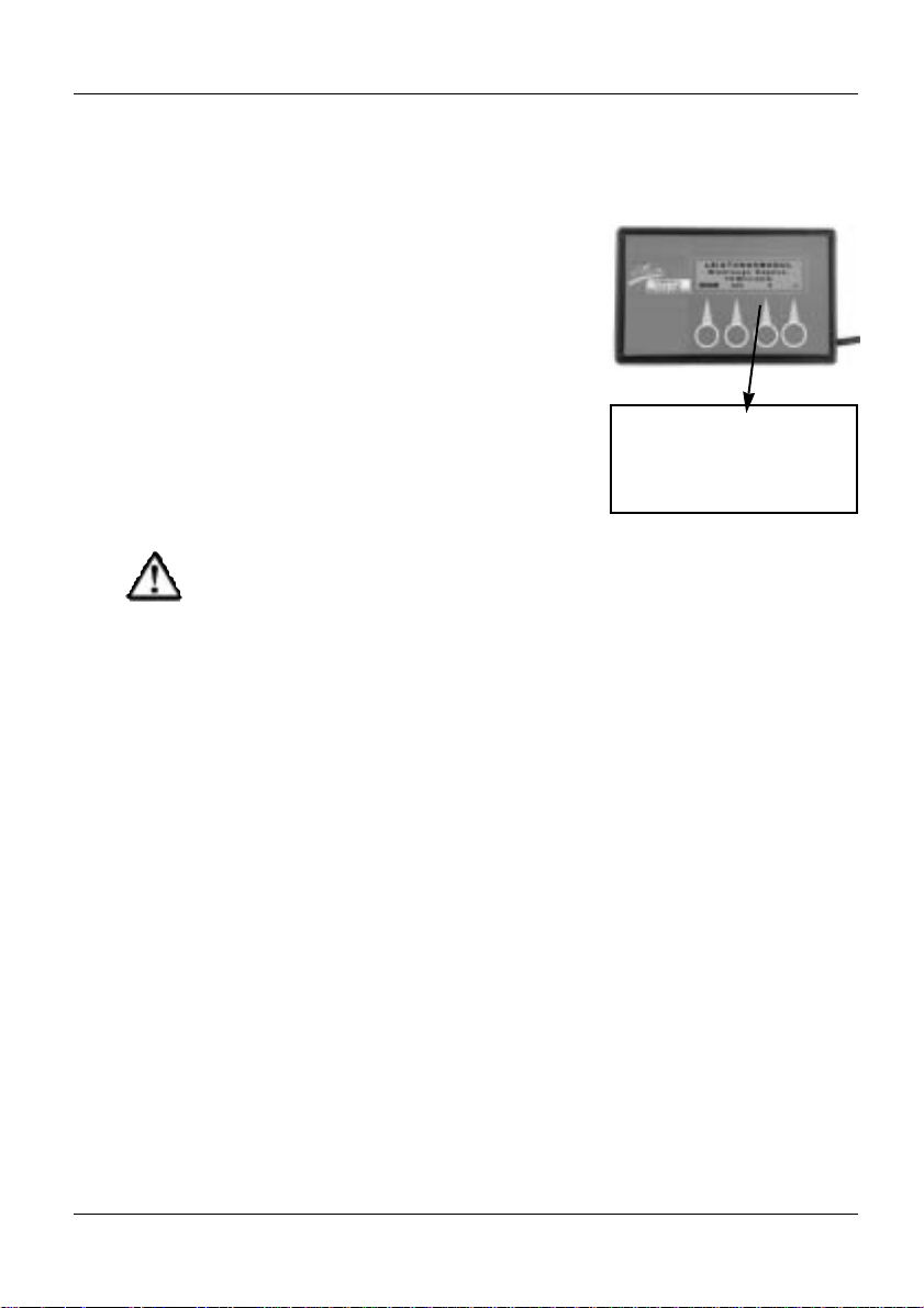
2.0 Connection / Type Number
Front
Type Plate
Type number
Back
3.0 The Push Keys
The input of the programming instructions is
performed by means of four push keys, which
are located in the lower area of the
programmers front part
The push keys are designed as membrane
keys which make the device resistant to
environmental influences.
Push Keys
4 Push Keys
The programmer is connected to the
programming socket of the joystick box by
means of the connection cable.
The location of the programming socket for the
connection of the programmer depends on the
type of joystick box being used.
You will find more details in the operation
instructions of the joystick boxes.
By means of the type number (P/No.), each
programmer can be easily related to the
corresponding operating instructions.
The present instructions belong to programmers
bearing the type number:
DX - HHP - FAS

7
Released: 03.2001
1.0 Short Instructions
1.1 Standard Programming . . . .8
1.2 Technician Mode . . . . . . . . . .9
2.0 Language Selection . .11
3.0 Displays in the Main
Menu: . . . . . . . . . . . . .11
4.0 “YES” Menu
4.1 Profiles 1 - 5 . . . . . . . . . . . .12
4.1.1 Minimum and maximum . . . . . .
forward, reverse and cornering
speeds . . . . . . . . . . . . . . . . .12
4.1.2 Forward, reverse and cornering
accelerations . . . . . . . . . . . . .13
4.1.3 Forward, reverse and cornering
deceleration . . . . . . . . . . . . .13
4.1.4 Grip . . . . . . . . . . . . . . . . . . .14
4.2 “YES” Menu:
Attendant Profile . . . . . . . . .14
4.3 “YES”-Menu:
Other Modules . . . . . . . . . . .15
5.0 “TECH” Menu
(Technician Mode) . . .15
5.1 Entering a Code . . . . . . . . .16
5.2 ”YES” Menu: Operating
Module (Master JS Module) 17
5.2.1 Joystick Calibration . . . . . . . .17
5.3 ”YES” Menu: Other Modules-
Power Module . . . . . . . . . . .18
5.3.1 Motor Compensation . . . . . . .18
5.3.2 Winding Compensation . . . . .19
5.4 ”YES” Menu in Tech. Mode:
Servo Steering Module . . . .20
5.4.1 Motor Compensation . . . . . . .20
5.4.2 Right Lock . . . . . . . . . . . . . .21
5.4.3 Left Lock . . . . . . . . . . . . . . . .22
5.4.4 Max. Motor Speed Calibration23
5.4.5 Restrictor Plate Calibration . .24
6.0 Error Diagnosis . . . . . .24
7.0 Operation
7.1 Function of the Keys . . . . . .25
7.2 Operation in the Main Menu 26
Technician Mode On . . . . . .26
7.3 “YES” Menu . . . . . . . . . . . .27
7.4 Technician Mode: Sequence 1 28
7.5 Technician Mode: Sequence 2 .28
7.6 Error Diagnosis: “DIAG”-
Menu . . . . . . . . . . . . . . . . . .29
7.7 Changing the Programming:
Profile 1-5/Attendant Profile 30
7.8 Technician Mode: Operation
Module (Master JS Module) 33
7.9 Technician Mode: Other
Modules - Power Module
. . . .34
7.10 Technician Mode: Other Mod.
Servo Steering Module . . . .35
Part A
Programming of REM 24 SC
Joystick Boxes
Table of Contents:

8
Released: 03.2001
+
–
Change
Value
1.0 Brief Instructions REM 24 SC Joystick Boxes
The following brief instructions shall give you a general idea of the
programming steps. It is imperative, however, to pay due attention to the
detailed instructions contained in chapter “Operation”.
The sequence and display of the described programming parameters
may differ according to the electronics of the wheelchair (i.e. G 40 /
STORM).
EXIT
Yes
View or Edit
Profile 1
YES ? DIAG TECH
View or Edit
Profile 2
View or Edit
Profile 3
View or Edit
Profile 4
>>>
Max. Forward Speed
Forward Acceleration
Min. Forward Speed
Forward Deceleration
Min. Reverse Speed
Max. Reverse Speed.
Reverse Acceleration
Reverse Deceleration
>>>
>>>
>>>
ENG FRA DEU ESPA
Select a Language
Edit Programming
continued next page
Scroll on
>>>
>>>
>>>
>>>
>>>
>>>
>>>
>>>
Chapter 1.2
1.1 Standard Programming

+
–
Change
Value
9
Released: 03.2001
continued next page
+
–
Change
Value
EXIT
Yes
View or Edit
Attendant Profile
View or Edit
Other Modules?*
>>>
Cornering Acceleration
Grip
Cornering Deceleration
>>>
>>>
Continuation
View or Edit
Profile 1
>>>
Repetition of
Main Menu
YES ? DIAG
Edit programming in technician mode
D1 = 5
Enter Technician Code
D3 = 2
EXIT
D2 = 9
View or Edit
Profile 1
Scroll
>>>
Master JS Module
JOYSTICK CALIBR.
>>>
1.2 Technician Mode
View or Edit
Profile 5
Max. Cornering Speed
>>>
>>>
>>>
+
–
Change
Value
Min. Cornering Speed
YES ? DIAG TECH
Edit Programming
* This parameter is not selectable
in all wheelchair electronics.
* This parameter does not appear
in all wheelchair electronics.
NOTE:
Changing of the sequence in the technician
mode is possible depending on the
wheelchair electronics!
or

>>>
>>>
>>>
10
Releaded: 03.2001
Change
Value
+
–
>>>
>>>
EXIT
Yes
Motor Compensation
Right
View or Edit
Power Module
View or Edit
Power Module
Winding Compensation
Yes
Change
Value
+
–
>>>
>>>
EXIT
Motor Compensation
Right
View or Edit
Servo Steering Module*
Right Lock
Left Lock
"
"
Change
Value
Max Motor Speed
Calibration
START
Start
Sequ
ence
Restrictor Plate
Calibration
START
Start
Sequence
Continued
View or Edit
Other Modules?
Yes
EXIT / >>>
View or Edit
Program 1
>>>
Repetition of
Main Menu
>>>
EXIT
Joystick Calibration
View or Edit
Operating Module
(Master JS Module)
START
Start
Sequence
Yes
* This parameter is not
selectable in all wheelchair
electronics.

11
Released: 03.2001
2.0 Selecting a Language
After the programmer is connected and the
joystick box is switched on, the first that will
appear will be the menu for selecting a
language.
The following languages can be selected:
English = Selection key: ENG
French = Selection key: FR
German = Selection key: DEU
Spanish = Selection key: ESPA
3.0 Displays in the Main Menu
After the language is selected, the main menu
will appear in the display window.
The following functions can be selected via
the keyboard:
YES = will switch into the menu for the
adjustment of the parameters, which
influence the wheelchair’s driving
behaviour.
? = not occupied
DIAG = serves to perform an error diagnosis
TECH = after entering an access code, will
switch into the expanded sub-menu
for the adjustment of the driving
parameters.
Technician Mode
DX HHP V 1.20
Select a language ....
ENG FRA DEU ESPA
Select a language:
View or Edit
System?
Yes ? DIAG TECH
Main Menu Display:

12
Released: 03.2001
Profiles 1 - 5:
Maximum Speed
*selected program No.
**editable value
P r o f i l e ...*
M a x. Forward Speed.
.....** %
EXIT >>> + –
4.1.1 Minimum* and maximum forward, reverse,
and cornering speeds
Designations:
forward speed = Vorwärtsgeschwindigkeit
reverse speed = Rückwärtsgeschwindigkeit
cornering speed = Drehgeschwindigkeit
This parameter allows a percentage
regulation of the forward, reverse and
cornering speeds at full deflection of the
joystick.
For each individual profile (drive mode) a
differently high speed can be entered
(%-value).
The graduation is performed in 5%-steps.
Settings:
10 % = lowest speed
100 % = highest speed
4.1 Profiles 1 - 5
The profile number appearing in the “YES”
menu corresponds to the respective drive
mode of the joystick box.
Profile 1 = Drive mode 1
Profile 2 = Drive mode 2
Profile 3 = Drive mode 3
Profile 4 = Drive mode 4
Profile 5 = Drive mode 5
By selecting the “YES” commands, you will
reach the sub-menu for the modification of the
parameters of profiles 1 to 5 and the
attendant profile.
4.0 “YES” Menu
Profile number
Advanced Mode
View or Edit
Profile: ..... ?
EXIT YES >>>
“YES”-Menu : Profiles 1 - 5
* All minimum values are relevant for Compact joystick boxes only.
For REM 24 SC joystick boxes the lowest value must be selected.

13
Released: 03.2001
4.1.2 Forward, Reverse and Cornering
Accelerations
This adjustment allows the percentage
regulation of the forward, reverse and
cornering accelerations.
The acceleration determines how fast the
motor will reach the adjusted maximum speed
at full deflection of the joystick.
For each single profile (driving mode) a
differently high acceleration value (%-value)
can be entered.
The graduation is performed in 5%-steps.
Adjustments:
10 % = lowest acceleteration
(slow response)
100 % = highest acceleration
(fast response)
Profiles 1 - 5:
Acceleration
*selected program No.
**editable value
P r o f i l e ...*
Forward Acceleration
.....** %
EXIT >>> + –
4.1.3 Forward, reverse and cornering
deceleration
This parameter allows the percentage
regulation of the forward, reverse and
cornering decelerations.
The decelerlation determines how fast the
motor will slow down to a standstill, after the
joystick is brought into the neutral position
= central position.
For each single profile (driving mode) different
deceleration values (%-values) can be entered.
The graduation is performed in 5%-steps.
Adjustments:
10 % = lowest deceleration
(slow speed reduction)
100 % = highest deceleration
(fast speed reduction)
Profiles 1 - 5:
Deceleration
*selected program No.
**editable value
P r o f i l e...*
Forward Deceleration
.....** %
EXIT >>> + –

14
Released: 03.2001
4.1.4 Grip
The adjustment of the grip will stabilise the
driving behaviour of the wheelchair when
entering and accelerating in curves.
For each individual driving mode a different
grip value can be entered.
The graduation is performed in 5%-steps.
Settings:
20 % = lowest setting
100 % = highest setting
Profiles 1 - 5: Grip
*selected program No.
**editable value
P r o f i l e...*
Grip
.....** %
EXIT >>> + –
4.2 “YES” Menu: Attendant Profile
The menu item ”Attendant Profile“ appearing in
the ”YES-Menu” serves to program an
additionally mounted joystick box, such as a
connectable joystick box for attendants.
By selecting the “YES” instructions, you will
reach the sub-menu for the modification of the
parameters.
The properties of the parameters to be
modified are described in sections 4.1.1 - 4.1.4
.
Advanced mode
View orEdit
Attendant Profile?
EXIT YES >>>
“YES” Menue:
Attendant Profil
NOTE:
“Attendant Profile” is not selectable in all
wheelchair electronics.

15
Released: 03.2001
5.0 “TECH” Menu (Technician Mode)
The technician mode (TECH), which can be
selected from the programmer’s main menu,
allows further interventions into the ACS
control’s driving modes.
The parameters of the technician mode are
protected and can only be reached by entering
the access code.
Technician Mode
CAUTION: Danger of Accident!
• Interventions into the technician mode’s parameters
are to be performed only after getting thoroughly
acquainted with these operating instructions.
• After each modification, the driving safety must always
be checked by means of a test drive.
NOTE:
Once the programmer’s plug connection is interrupted, the
technician mode will be automatically saved again.
4.3 “YES”Menu: Other modules
The menu option “Other modules“ is not
selectable in all wheelchair electronics.
For programming this option, the technician
mode must be switched on.
Advanced mode
View or Edit
Other modules?
EXIT YES >>>
“YES” Menu:
Other Modules
NOTE:
For programming this option, the
technician mode must be switched
on.
View or Edit
System?
YES ? DIAG TECH

16
Released: 03.2001
5.1 Entering the Code
By activating the "TECH"-key you will reach
the level, where the technician code is entered.
The access code for the technician mode is:
* 5 * 9 * 2 *
Entering Sequence:
5 x D1 * 9 x D2 * 2 x D3 plus EXIT.
592
Technician Mode
Enter Code
0 0 0
EXIT D1 D2 D3
“TECH” Menu:
Enter the Code
After the input is terminated, the main menu
will be displayed again.
After activating the ”YES” key, the parameters
described in section 4.0 (“YES” menu) can be
adjusted.
In addition, the parameters described starting
section 5.2 “YES-Menu in the Technician
Mode” are selectable and editable.
View or Edit
System?
YES ? DIAG TECH
Display of Main Menu:
NOTE:
The technician mode can be
exited only after disconnecting
the programmer’s plug connection.

17
Released: 03.2001
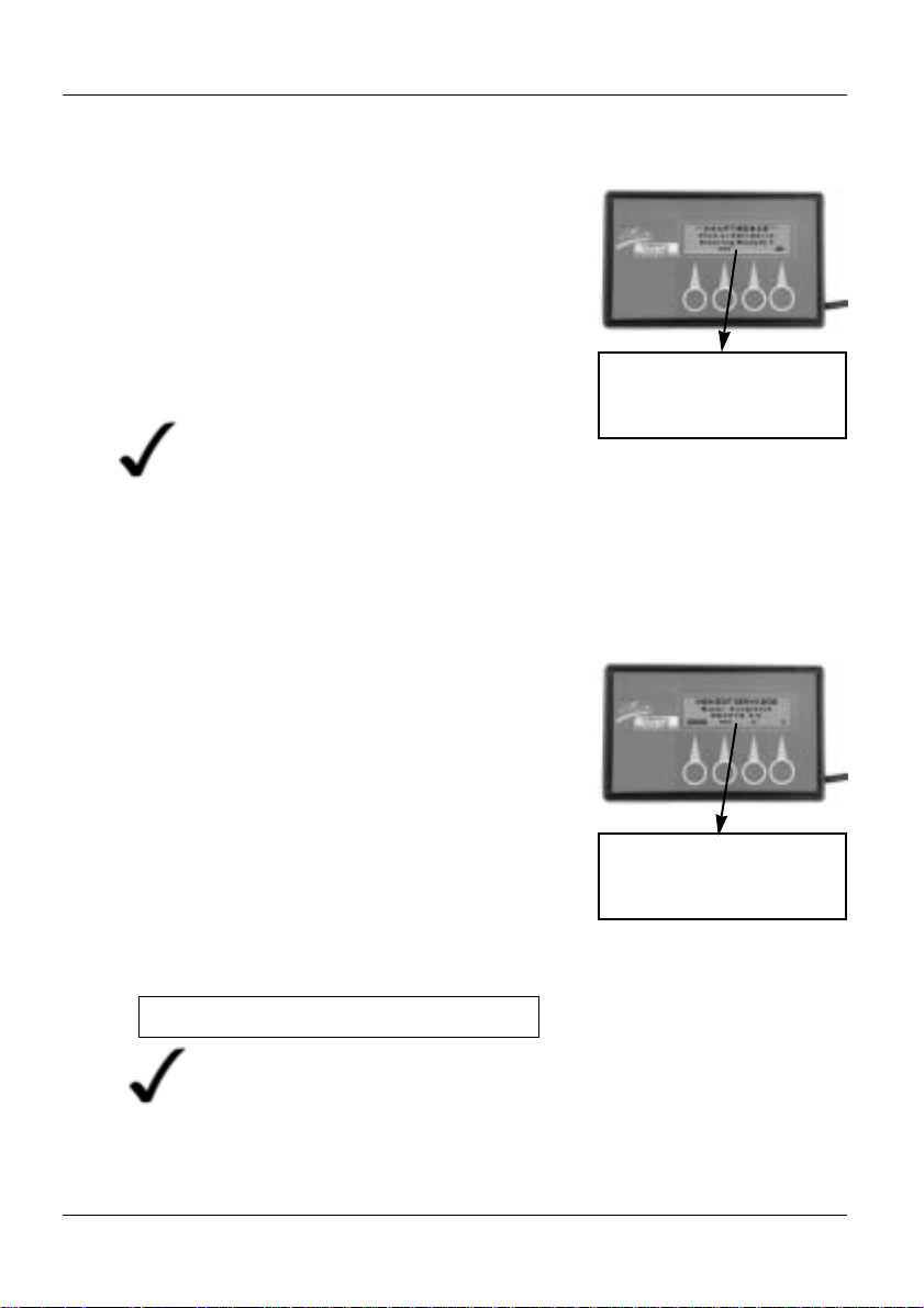
5.2 “YES” Menu in the Technician Mode:
Operating Module (Master JS Module)
The term control module appearing in the “YES”Menu allows an intervention into the settings of
the joystick box.
By selecting the “YES” commands you will reach
the sub-menu for the modification of the
following parameters.
Advanced mode
View or Edit
Master JS Modul
EXIT YES >>>
“YES”-Menu:
Control Module
Control Module:
Joystick Calibration
JOYSTICK CALIBR.
EXIT START
JOYSTICK KALIBR.
Rotate Joystick
""
Neutral ""STOP
EXIT STOP
By selecting the “START” commands you will
reach the sub-menu for the calibration of the
joystick.
Sub-Menu:
Sequence of Commands:
Rotate joystick = to move the joystick along
the restrictor plate in a
rotating way
Neutral = Guide joystick into the
central (neutral) position
STOP = Save sequence by pressing
down the STOP key.
EXIT = Causes the termination of
the option without saving.
Restrictor Plate = mechanical restrictions of
the joystick movements
5.2.1 Joystick Calibration
When calibrating the joystick, the positions of
the joystick’s driving directions are
programmed into the electronics.
The calibration is only required after a replacement of the joystick.
Rotating the Joyjstick:
or “operating module”, depending on the electronics

18
Released: 03.2001
Performance Module:
Motor Compensation
**editable value
Power Module
Motor Compensation
RIGHT .....** %
EXIT >>>
"
5.3.1 Motor Compensation
This parameter allows the percentage
adaptation of the synchronization of the right
and left motors.
Only if both motors are synchronized, an exact
directional stability of the power wheelchair
can be guaranteed.
An adjustment of this parameter may become
necessary, for instance, after the replacement
of a driving motor.
The graduation is performed in 1%-steps.
Settings:
= slowing down left motor
= slowing down right motor
"
"
"
5.3 The “YES”Menu in Technician
Mode: Power Module
The term power module appearing under
"other modules" in the technician mode, allows
the intervention into the electronics of the main
module.
By selecting the “YES” commands you will
reach the sub-menu for the modification of the
following parameters.
** Main Menu **
Read or Edit
Power Module
>>> YES
“YES” Menu:
Power Module
19
Stand: 03.2001
5.3.2 Winding Compensation
This parameter is necessary for matching the
electronics to the different types of motors.
The value is preset by the factory and may not
be modified by any means.
Setting Values and Driving Properties:
Value too low = steering movements not
precise
Value too high = jerking driving movements
jerking, unprecise steering
movements
Power Module:
Winding
Compensation
POWER MODULE
Winding Compens.
?? Milliohm
EXIT >>> + –
CAUTION: Danger of Accident
An incorrect setting leads to uncontrollable driving movements.
Do NOT modify the setting!
20
Released: 03.2001
5.4.1 Motor Compensation
This parameter allows the adjustment of the
directional position of the servo steering motor.
The adjustment of this parameter can become
necessary, for example, following the replacement of a servo steering motor.
Settings:
= adjusting motor to the left
graduation 0 - 128 left (left correction)
= adjusting motor to the right
graduation: 0 - 128 right
(right correction)
Servo Steering Module:
Motor Compensation
**editable valuet
VIEW/EDIT SERVO MOD
Motor Compensation
Right .....**
EXIT >>>
"
Standard setting = RIGHT 0 %
"
"
"
NOTE:
Due to the small graduation steps, a very precise
adjustment of the directional stability is made possible.
A visible change is hard to detect, that is why the
wheels must be carefully observed.
5.4 “YES”Menu in the Technician Mode:
Servo Steering Module
The definition Servo Steering Module
appearing in the technician mode under
"Other Modules" allows an intervention into
the electronics of the servo/lighting module.
By selecting the “YES” command, you will
open the sub-menu for modifying the following
parameters.
** Main Menu **
View or Edit Servo
Steering Module ?
>>> YES
“YES”Menu:
Servo Steering Module
NOTE:
This parameter is only editable in power
wheelchairs that are provided with a
servo steering motor.

21
Released: 03.2001
5.4.2 Right Lock
This parameter allows the adjustment of
the maximum right steering deflection.
The graduation is performed in 1%-steps
Servo Steering Module:
Right Lock
**editable value
VIEW/EDIT SERVO MOD
Right Lock
.....** %
EXIT >>> + –
NOTE:
If the lever of the servo steering motor
touches the mechanical lock, it can lead
to its destruction.
CAUTION: Danger of Accident
The activation of this setting makes the
wheels turn automatically inward.
Default setting = RIGHT 79 %
Settings:
+ = deflection closer to the mechanical
steering lock
– = deflection farther away from the
mechanical steering lock
Adjusting measure:
Air gap of 1 mm to the mechanical steering
lock at maximum steering deflection.

22
Released: 03.2001
Servo Steering Module:
Left Lock
**editable valuet
VIEW/EDIT SERVO MOD
Left Lock
.....** %
EXIT >>> + –
Default setting = LEFT 25 %
5.4.3 Left Lock
This parameter allows the adjustment of the
maximum left steering deflection.
The graduation is performed in 1%-steps.
NOTE:
If the lever of the servo steering motor
comes into touch with the mechanic
steering lock, it can lead to its
destruction.
CAUTION: Danger of Accident
The activation of this setting makes the
wheels turn automatically inward.
Settings:
+ = deflection closer to the mechanic steering
lock
– = deflection farther away from the
mechanic steering lock
Adjusting measure:
Air gap of 1 mm to the mechanic steering locks
at maximum steering deflection.

23
Released: 03.2001
Servo Steering Module:
Max motor speed
calibration
VIEW/EDIT SERVO MOD
Max motor speed
calibration
EXIT >>> START
5.4.4 Maximum Motor Speed Calibration
This parameter performs the adjustment of the
electronics to the servo steering motor’s
maximum obtainable steering speed.
The adjustment takes place automatically
after the function is activated (START).
It is done at the factory and no adjustment is
required.
CAUTION: Danger of Accident
The activation of this adjustment makes
the wheels turn automatically inward.
Setting:
Should a calibration be necessary, the power
wheelchair concerned must be subjected to a
test load.
Test load = 140 kg

24
Released: 03.2001
6.0 “DIAG” = Error Diagnosis
The DIAG key appearing in the main menu
allows the performance of a diagnosis of the
entire ACS-system.
In the presence of a malfunction in the system,
the number of the error will be displayed.
The error number shown corresponds to the
error code of the joystick box.
Example:
Error number 1 = flash code 1 x flashing
You will find a list of error codes in the annex.
D X D I A G N O S T I C S
Flash Code....*
N1 Park brake
EXIT >>>
“DIAG” = Error Test
*Error Number
Servo Steering Module:
Restrictor Plate
VIEW/EDIT SERVO MOD
Restrictor Plate
Calibration
EXIT >>> START
5.4.5 Restrictor Plate Calibration
This parameter adapts the servo steering
motor to the joystick restrictor plate. This
causes the servo steering motor to turn the
maximum joystick deflection to the right and to
the left exactly into the maximum steering
movement.
The adjustment is performed at the factory and
no further adjustment is necessary.
RESTRICTOR PLATE CALIB.
Trace Joystick
outline
EXIT SAVE
Sub-Menu
Sequence of commands:
Trace Joystick = Move the joystick along the
restrictor plate in a rotating
motion.
SAVE = Save the sequence by
pressing the SAVE key
EXIT = Causes the cancellation of
the option without saving.
*Restrictor Plate = mechanical limitation of the
the joystick movements
By selecting the “START” command you will
open the sub-menu for the calibration of the
joystick.
Trace Joystick:
(Rotate Joystick )

25
Stand: 03.2001
7.1 Function of the Key Symbols
= Serves to save a sequence while simultaneously returning
to an upper menu.
= Scrolling the menu items.
= Switches from the main menu to a sub-menu.
= Increases (+) / decreases (–) the setting value.
= Changes direction-related adjustment values.
Adjustment direction to the left ( )/ to the right (")
= Starts a sub-menu providing calibration and triggering or
requiring movements.
= Serves to save a sequence while simultaneously terminating
the programming sequence.
EXIT
>>>
YES
+ –
START
"
STOP
"
"
7.0 Operation
The sequence and the display language of the described programming
steps depend on the electronics of the power wheelchair.
Example:
Master JS Module (G40) = Operating module (STORM)
Should a desired programming parameter not appear at the position
shown, you will reach it by “scrolling” [>>>] the sequence menu.

26
Released: 03.2001
DX HHP V 1.20
Select a language ....
ENG FRA DEU ESPA
1. Connect programmer
to the joystick box:
2. Switch on joystick
box:
Chair not responding
Turn power on !
3. Select a language:
4. Edit programming :
Switch ON technician
mode
Error diagnosis (Chapter 7.6)
Edit programming
(Chapter 7.3)
7.2 Operations in the Main Menu
Display
Read or Edit
System?
YES ? DIAG TECH
Technician Mode
Enter Code
0 0 0
E D1 D2 D3
1. Enter Code:
5 9 2
Cancel
Technician Mode
Enter Code
5 9 2
EXIT D1 D2 D3
2. Confirm:
View or Edit
System?
YES ? DIAG TECH
CAUTION:
Danger of
Accident!
• After each
modification,
the driving
safety must
be verified
by means of
a test drive.
Programming Sequence
(Chapter 7.5)
Programming Sequence
(Chapter 7.4)
Technician Mode
Master JS Module
JOYSTICK CALIBR.
EXIT YES >>>
Depending on the wheelchair’s
electronics, the following windows
will appear

27
Released: 03.2001
Edit Programming (Chapter 7.7)
Edit Programming (Chapter 7.7)
Edit Programming (Chapter 7.7)
7.3 Operation in the “YES” Menu
Display
4. Repeat Menu
Advanced Mode
View or Edit
Profile: 1 ?
EXIT YES >>>
To Main Menu
Continue to Profiles
2 to 5
Scroll on
1. Profile 1....
2. Attendant Profile
3. Other Modules
Select up to Profile 5
To Main Menu
Advanced Mode
View or Edit
Profile: 5 ?
EXIT YES >>>
To Main Menu:
Scroll on
Advanced Mode
View or Edit
Attendant Profile?
EXIT YES >>>
Advanced Mode
View or Edit
Profile: 1 ?
EXIT YES >>>
Edit Programming.
Only possible inTechnician Mode!
Scroll on
To Main Menu
Advanced mode
View or Edit
Other modules?
EXIT YES >>>

28
Released: 03.2001
7.4 Technician Mode: Sequence 1
7.5 Technician Mode: Sequence 2
The following program points can only be selected when the
technician mode is switched on (Chapter 7.2, Switch ON technician mode!)
Display
The following program points can only be selected when the technician
mode is switched on (Chapter 7.2, Switch Technician Mode ON)!
Display
Scroll on
Scroll on
To Main Menu
To Main Module
Advanced mode
View or Edit
Operation Mode
EXIT YES >>>
3. Repeat Menu
Advanced Mode
View or Edit
Profile: 1 ?
EXIT YES >>>
2. Select other
Modules in the
Technician Mode-
Scroll on
To Main Menu
Advanced Mode
View or Edit
Other Modules?
EXIT YES >>>
Edit Programming (Chapter7.8)
Edit Programming (Chapter 7.9)
Technician Mode
Master JS Module
JOYSTICK CALIBR.
EXIT YES >>>
Edit Programming (Chapter 7.6)
continued next page
1. Select Operation
Module in the
Technician Mode
1. Master JS Module =
Operation Module in
Technician Mode

29
Released: 03.2001
4. Repeat Menu
Advanced mode
View or Edit
Profile: 1 ?
EXIT YES >>>
D X D I A G N O S T I C S
Flash Code....*
N1 Park Brake
EXIT >>>
7.6 Error Diagnosis: “DIAG” Menu
1.Activate Test
Scroll On
No. of Error Code.
Error Code List in the
Annex
To Main Menu
View or Edit
System?
YES ? DIAG TECH
** Main Menu **
View or Edit
Power Module
>>> YES
Scroll on
Edit Programming (Chapter 7.9)
Scroll on
Edit Programming (Chapter 7.10)
** Main Menu*
View or Edit
Servo.Steering-Module
>>> YES
Continuation:
2. The Power Module in
the Technician Mode
3. Servo Steering Module
= Servo Steering in
the Technician Mode

30
Released: 03.2001
Display
Change Value
** Main MENU **
View or Edit
Profile: 1 ?
>>> YES
to Program 5 and Attendant Profile
P r o f i l e ...*
Forward Acceleration
.....** %
EXIT >>> + –
P r o f i l e ...*
Forward Deceleration
EXIT >>> + –
P r o f i l e ...*
Max. Forward Speed
.....** %
EXIT >>> + –
P r o f i l e ...*
Min forward speed
.....** %
EXIT >>> + –
1. Maximum ForwardSpeed
To Main Menu
Scroll on
2. Minimum ForwardSpeed
Change Value
To Main Menu
Scroll on
3. Forward Acceleration
Change Value
To Main Menu
Scroll on
Change Value
P r o f i l e ...*
Max. Reverse Speed
.....** %
EXIT >>> + –
4. Forward Deceleration
To Main Menu
Scroll on
5. Maximum Reverse
Speed
Change Value
To Main Menu
Scroll on
continued next page
7.7 Edit Programming: Profiles 1 - 5 / Attendant Profile

31
Stand: 03.2001
Continuation:
Display
P r o f i l e ...*
Reverse Deceleration
.....** %
EXIT >>> + –
6. Minimum ReverseSpeed
Change Value
To Main Menu
Scroll on
Change Value
P r o f i l e ...*
Max. Cornering Speed
.....** %
EXIT >>> + –
P r o f i l e ...*
Min. Cornering Speed
.....** %
EXIT >>> + –
7. Reverse Acceleration
To Main Menu
Scroll on
8. Reverse Deceleration
Change Value
To Main Menu
Scroll on
9. Maximum Cornering
Speed
Change Value
To Main Menu
Scroll on
10. Minimum Cornering
Speed
Change Value
To Main Menu
Scroll on
continued next page
P r o f i l e ...*
Reverse Acceleration
.....** %
EXIT >>> + –
P r o f i l e ...*
Min Reverse Speed
.....** %
EXIT >>> + –

32
Released: 03.2001
11 Cornering
Acceleration
Toggle Option
To Main Menu
Scroll on
Continuation:
Display
12. Cornering
Deceleration
13. Grip
Toggle Option
To Main Menu
Scroll on
Toggle Option
To Main Menu
Scroll on
14. Repetition of
sub-menu:
P r o f i l e ...*
M a x. Forward Speed
.....** %
EXIT >>> + –
P r o f i l e ...*
Cornering Deceleration
.....** %
EXIT >>> + –
P r o f i l e ...*
Cornering Acceleration
.....** %
EXIT >>> + –
P r o f i l e ...*
G r i p
.....** %
EXIT >>> + –

33
Reelase: 03.2001
JOYSTICK CALIBR.
EXIT START
Advanced Mode
View or Edit
Operation Module
EXIT YES >>>
2. Repetition of the
Sub-Menu
Sequence:
JOYSTICK CALIBR.
Rotate Joystick
" Neutral " STOP
EXIT STOP
7.8 Edit Programming (Technician Mode):
“Operation Module (Master JS Modul)”
1. Calibrate Joystick
Adjustments
Start Sequence
Save
sequence
after
termination
Cancellation
without Saving.
• Rotate joystick
along the restrictor
plate.
• Guide joystick into
central position
To Main Menu
JOYSTICK CALIBR.
EXIT START
Advanced Mode
View or Edit
...........
EXIT YES >>>
Technician Mode
Master JS Module
JOYSTICK CALIBR.
EXIT YES >>>

34
Stand: 03.2001
7.9 Edit Programming (Technician Mode):
“Other Modules - Power Module”
Display
Change Value
1. Motor
Compensation
To Main Menu
To Main Menu
Scroll on
2. Winding
Compensation
Change Value
Back to sub-menu
Scroll on
POWER MODULE
Motor Compensation
RIGHT.....** %
EXIT >>>
"
"
POWER MODULE
Winding Compens.
?? Milliohm
EXIT >>> + –
3. Repetition of the
Sub-Menu:
POWER MODULE
Motor Compensation
RIGHT .....** %
EXIT >>>
"
"
Advanced mode
View or Edit
Other modules?
EXIT YES >>>
**MAIN MENU **
View or Edit
Power Module
>>> YES

35
Released: 03.2001
Change Value
1. Motor
Compensation
To Main Menu
Scroll on
2. Right Steering
Deflection
Change Value
To Main Menu
Scroll on
VIEW/EDIT SERVO MOD
Motor Compensation
Right .....**
EXIT >>>
"
"
VIEW/EDIT SERVO MOD
Left Lock
.....** %
EXIT >>> + –
VIEW/EDIT SERVO MOD
Right Lock
.....** %
EXIT >>> + –
3. Left Steering
Deflection
Change Value
To Main Menu
Scroll on
4. Steering Speed
Start Sequence
To Main Menu
Scroll on
VIEW/EDIT SERVO MOD
Max Motor Speed
Calibration
EXIT >>> START
continued next page
7.10 Edit Programming (Technician Mode):
“Other Modules - Servo Steering Module”
Display
To Main Menu
Advanced Mode
View or Edit
Other modules?
EXIT YES >>>
**MAIN MENU **
View or Edit
Servo.Steering-Module
>>> YES

36
Repetition: 03.2001
Sequence:
6. Repetition of the
Sub-Menu
5. Adapt Servo
Steering to Joystick
Start Sequence
Scroll on
Continuation:
Display
VIEW/EDIT SERVO MOD
Restrictor Plate
Calibration
EXIT >>> START
RESTRICTOR PLATE CALIB.
Trace Joystick
outline
EXIT SAVE
Save
sequence
after
termination.
Cancellation
without Saving
• Move joystick
along restrictor
plate in rotating
motion.
VIEW/EDIT SERVO MOD
Restrictor Plate
Calibration
EXIT >>> START
To Main Menu
VIEW/EDIT SERVO MOD
Motor Compensation
Right .....**
EXIT >>>
"
"

37
Released: 03.2001
PART B
Pogramming of
ACS Compact Joystick Boxes
Table of Contents:
1.0 Brief Instructions
1.1 Standard Programming . . . .38
1.2 Technician Mode . . . . . . . . .40
2.0 CHAIR SPEED -
Maximum Speed . . . . .41
3.0 RESPONSE -
Driving Behaviour . . . .41
4.0 Advanced Mode . . . . .42
5.0 “Advanced Mode”
Menu . . . . . . . . . . . . . .42
5.1 Profile 3 . . . . . . . . . . . . . . . .42
5.1.1 Minimum and Maximum . . . . .
Forward, Reverse and
Cornering Speeds. . . . . . . . .43
5.1.2 Forward, Reverse and
Cornering Accelerations . . . .43
5.1.3 Forward, Reverse and
Cornering Deceleration . . . . .44
5.1.4 Grip . . . . . . . . . . . . . . . . . . .45
5.2 “Advanced Mode” Menu:
Attendant Profile . . . . . . . . .45
6.0 “TECH” Menu . . . . . . .45
6.1 Entering Code . . . . . . . . . .46
6.2 Technician Mode: Master JS
Module (Operation Module) 47
6.2.1 Joystick Calibration . . . . . . . .47
6.3 Technician Mode: Motor
Settings . . . . . . . . . . . . . . . .48
6.3.1 Motor Compensation . . . . . . .48
6.3.2 Winding Compensation . . . . .49
7.0 Error Diagnosis . . . . . .49
8.0 Operation
8.1 Function of Keys . . . . . . . . .50
8.2 Operation in the Main Menu 50
Technician Mode on . . . . . .51
8.3 “Advanced Mode” Menu . . .52
8.4 Error Diagnosis: “DIAG”-
Menu . . . . . . . . . . . . . . . . . .53
8.5 Edit Programming:
Profile 3 / Attendant Profile 53
8.6 Technician Mode:
8.6.1 Master JS Module . . . . . . . .56
8.6.2 Motor Settings . . . . . . . . . . .57

38
Released 03.2001
+
–
+
–
1.0 Brief Instructions - ACS Compact Joystick Boxes
The following brief instructions shall give you a general idea of the
programming steps. It is imperative, however, to pay due attention to the
detailed instructions contained in chapter “Operation”.
The sequence and display of the described programming parameters may
differ according to the electronics of the wheelchair
Change
Value
EXIT
Yes
View or Edit
Profile 3?
>>>
Change
Value
+
–
Change
Value
Response
(Response Behaviour)
Advanced Mode
Expanded Mode)
YES >>> DIAG TECH
Edit Programming
continued next page
Scroll on
>>>
>>>
>>>
>>>
>>>
View or Edit
Attendant Profile?
View or Edit
Profile 3
>>>
Repetition of the
Main Menu
Chapter 1.2
Chair Speed
(Forward Speed
1.1 Standard Programming
Maximum Forward Speed
Forward Acceleration
Minimum Forward Speed
ENG FRA DEU ESPA
Select a Language

39
Stand: 03.2001
+
–
Change
Value
+
–
Change
Value
+
–
Change
Value
Reverse Acceleration
Maximum Cornerning Speed
Reverse Deceleration
>>>
>>>
>>>
>>>
Minimum Cornering Speed
>>>
Cornering Acceleration
Grip
Cornering Deceleration
>>>
>>>
Max. Forward Speed
Continuation
EXIT
+
–
Change
Value
>>>
>>>
>>>
Forward Deceleration
Minimum Reverse Speed
Maximum Reverse Speed.

40
Released: 03.2001
Change
Value
+
–
NEXT
EXIT
YES
Motor Compensation
Right
View or Edit
Motor Settings
Winding Compensation
>>>
EXIT
Joystick Calibration
Master JS Module
Joystick Calibration
START
Start
Sequence
YES
Advanced Mode
(Expanded Mode)
YES >>> DIAG TECH
D1 = 5
Enter Technician
Code
D3 = 2
EXIT
D2 = 9
View or Edit
Profile 3
NEXT
Repetition of the
Menu
1.2 Technician Mode

41
Released: 03.2001
CHAIR SPEED
Min. ########## Max.
? >>> – +
RESPONSE
3*
? >>> – +
CHAIR SPEED
2.0 CHAIR SPEED - Maximum
Speed
This parameter allows the regulation of the
speed at full deflection of the joystick. This
influences the forward, reverse and cornering
speeds.
The number of #-symbols determines the
speed selected.
Settings:
1 # -symbol = lowest speed
10 # -symbols = highest speed
3.0 RESPONSE - Driving Behaviour
This parameter allows the basic setting of the
wheelchair’s driving behaviour. By changing
the parameters described in paragraph 5.0, a
fine adjustment of the driving behaviour can be
performed.
The graduation is performed in 5 steps.
Settings:
5 = fast driving behaviour
1 = slow driving behaviour
RESPONSE
*editable value

42
Released: 03.2001
5.1 Profile 3
The profile number 3 appearing in the
“Advanced Mode” menu corresponds to
the response setting of the joystick box.
By selecting the “YES” command you will
open the sub-menu for editing the driving
parameters..
5.0 “Advanced Mode” Menu
Profile Number
Advanced Mode
View or Edit
Profile 3 ?
EXIT Yes >>>
“Advanced Mode”
Menu: Profile 3
4.0 Advanced Mode - expanded
mode
The advanced mode allows the adjustment of
individual parameters, which influence the
wheelchair’s driving behaviour.
The following functions can be selected by
means of the keyboard:
YES = switches into the menu for the
adjustment of the driving parameters.
>>> = switches to the next menu point
DIAG = serves to perform an error
diagnosis
TECH = after entering an access code,
switches into the expanded sub-menu
for the adjustment of the driving
parameters. Technician Mode.
GO TO
Advanced mode?
Yes >>> DIAG TECH
Advanced Mode
(Expanded Mode)

43
Released: 03.2001
5.1.1 Minimum and Maximum Forward, Reverse
and Cornering Speeds
(Forward, Reverse and Cornering Speeds)
Designations:
forward speed
reverse speed
cornering speed
This parameter provides the percentage
regulation of the forward, reverse and
cornering speeds at full deflection of
the joystick.
The graduation is performed in 5%-steps.
Settings:
10 % = lowest speed
100 % = highest speed
Profile 3:
Maximum Speed
**editable value
P r o f i l e 3
Maximum Forward Speed
.....** %
EXIT >>> – +
5.1.2 Forward, Reverse and Cornering
Accelerations
This setting allows the regulation of the
forward, reverse and cornering accelerations.
The acceleration determines how fast the
motor will reach the adjusted maximum speed
at full deflection of the joystick.
To each single profile (driving mode) a
differently high acceleration value (%-value)
can be assigned.
The graduation is performed in 5%-steps.
Settings:
10 % = lowest acceleration
(slow reaction)
100 % = highest acceleration
(quick reaction)
Profile 3: Acceleration
**editable value
P r o f i l e 3
Forward Acceleration
.....** %
EXIT >>> – +

44
Released 03.2001
5.1.3 Foreward, Reverse and Cornering
Decelerations
This parameter provides the percentage
regulation of the forward, reverse and
cornering decelerations.
The deceleration determines how fast the
motor will slow down to the point of coming to
a standstill, after the joystick has been brought
into the neutral position = central position.
To each single profile (driving mode) different
decerlation values (%-value) can be assigned.
The deceleration can be performed in 5%steps.
Settings:
10 % = lowest deceleration
(slow braking)
100 % = highest deceleration
(fast braking )
Profile 3: Deceleration
**editable value
P r o f i l 3
Forward Deceleration
.....** %
EXIT >>> – +
5.1.4 Grip
The adjustment of the grip stabilises the
driving behaviour of the wheelchair when
turning and accelerating in curves.
To each single driving mode a differently
high grip value can be assigned.
The graduation is performed in 5%-steps.
Settings:
20 % = lowest setting
100 % = highest setting
Profile 3: Grip
**editable value
P r o f i l 3
Grip
.....** %
EXIT >>> – +

45
Stand: 03.2001
5.2 “Advanced Mode” Menu:
Attendant Profile
The menu point ”Attendant Profile“ appearing
in the ”Advanced Mode” Menu serves to program an additonally mounted joystick box,
such as the connectable joystick box for attendants.
By selecting the “YES” command you will
reach the sub-menu for editing the driving
parameters.
The properties of the parameters to be edited
are described in paragraphs 5.1.1 - 5.1.4.
Advanced mode
View or Edit
Attendant Profile?
EXIT YES >>>
“Advanced Mode”:
Attendant Profile
6.0 “TECH” Menu
(Technician Mode)
The technician mode (TECH) selectable in the
“advanced mode” display of the programmer
allows further interventions into the
ACS-control’s driving parameters.
The parameters of the technician mode are
protected and can only be reached by entering
the access code.
Technician Mode
ATTENTION: Danger of Accident!
• Any interventions into the technician code should only
be performed after getting thoroughly acquainted with
the present operating instructions..
• It is imperative to verify the driving safety after each
modification by means of a test drive.
NOTE:
After separating the programmer’s plug connection, the
technician mode will automatically be saved again.
GO TO
Advanced Mode?
YES >>> DIAG TECH

46
Stand: 03.2001
6.1 Enter Code
By activating the "TECH" key you will reach
the level for entering the technician code.
The access code is:
* 5 * 9 * 2 *
Input Sequence:
5 x D1 * 9 x D2 * 2 x D3 and
confirm with EXIT
.
After confirming with the “EXIT” key, the
parameters described in paragraph 5.0
(“Attendant Profile” menu) can be edited.
Additionally selectable and editable are the
parameters described in the “YES/TECH”
menu from paragraph 6.2 on.
“Technician Mode”Master JS Module
NOTE:
You can exit from the technician mode
only by separating the plug connection
of the programmer.
592
Technician Mode
Enter Code
0 0 0
EXIT D1 D2 D3
“TECH” Menu:
Enter Code
Technician Mode
Master JS Module
JOYSTICK CALIBR.
EXIT YES >>>

47
Released: 03.2001
6.2 Technician Mode:
Master JS Module (Operating Module)
The term Master JS Module (operating module)
appearing in the “YES” menu allows an intervention into the settings of the joystick box.
By selecting the “YES”command you will reach
the sub-menu for the calibration of the joystick.
Master JS Module
(Operation Module)
Sub-Menu:
Joystick Calibration
JOYSTICK CALIBR.
Rotate Joystick
""
Neutral ""STOP
EXIT STOP
Sequence of Commands:
Rotate Joystick = Move joystick along the
restrictor plate in rotating
motions.
Neutral = Guide joystick into the
central position (neutral)
STOP After termination, save/
confirm sequence by
pressing down STOP key.
EXIT = Causes the cancellation
of the option without saving.
Restrictor Plate = mechanical restriction of the
joystick movements
6.2.1 Joystick Calibration
During the calibration of the joystick the
adjustments of the joystick’s driving directions
are programmed into the electronics.
The calibration is only necesary after the
replacement of the joystick.
Rotate Joystick:
Technician Mode
Master JS Module
JOYSTICK C ALIBR.
EXIT YES >>>

48
Released: 03.2001
Motor Compensation
6.3.1 Motor Compensation
This parameter allows the percentage
synchronization of the right and the left motor.
Only when both motors run in the same
direction, an exact directional stability of the
wheelchair can be guaranteed.
The adjustment of this parameter can
become necessary, for example, after the
replacement of a drive motor.
The graduation is performed in 1%-steps.
Settings:
= slow down left motor
= slow down right motor
Standard Setting = RIGHT 0 %
6.3 Technician Mode: Motor Settings
The "Motor Settings" in the technician mode
allow an intervention into the electronics of themain module.
By selecting the “YES” command you will
reach the sub-menu for editing the following
parameters.
Technician Mode
View or Edit
Motor Settings
YES NEXT
Motor Settings
**editable value
Technician Mode
Motor Compensation
RIGHT ..** %
EXIT
"
NEXT
"
"
"

49
Released: 03.2001
6.3.2 Winding Compensation
This parameter is necessary for adapting the
electronics to the different types of motors.
The value is preset at the factory and is not
allowed to be changed by any means.
Setting Values and Driving Properties:
Value too low = Unprecise steering
movements
Value too high = jerky driving movements
jerky, unprecise steering
movements
Winding
Compensation
CAUTION: Danger of Accident
An incorrect setting leads to uncontrollable driving movements.
Do NOT change setting!
7.0 “DIAG” = Error diagnosis
The DIAG key appearing in the main menu
serves to carry out a diagnosis of the entire
ACS system.
In the presence of a malfunction, the number of
the error will be displayed.
The error number displayed corresponds to the
error code of the joystick box.
Example:
Error number 1 = blinking code 1 x blinking
You will find a list of the error codes in the
annex.
D X D I A G N O S T I C S
Blinking Code....*
N1 Parking
Brake
EXIT >>>
“DIAG” = Error Check
*Error Number
**editable value
Technician Mode
Winding Compens.
?? milliohm
EXIT – + NEXT

50
Released: 03.2001
8.1 Function of the Key Symbols
= Serves to save a sequence while simultaneously
returning into an upper menu.
= Scroll through the menu items.
= Switch from the main menu to a sub-menu.
= Increase (+) / decrease (–) setting value.
= Changes direction-related adjustment values.
Adjustment direction to the left ( ) / to the right (")
= Starts a sub-menu which serves calibration and triggers or
requires movements.
= Serves to save a sequence while simultaneously terminating
the programming sequence.
"
1. Connect programmer
to joystick box:
2. Switch on joystick
box:
Chair not responding
Turn power on !
8.2 Operation in the Main Menu
Display
NEXT
continued next page
EXIT
>>>
YES
+ –
START
"
STOP
"
8.0 Operation
The sequence and the display language of the programming steps
depends on the electronics of the wheelchairs.
Should a programming parameter not appear at the position shown, it
can be reached by “scroll on” [>>>] of the sequence menu.
or

51
Released: 03.2001
Change Value
RESPONSE
3*
? >>> – +
4. Switch on
Response Behaviour:
to Main Menu
Scroll on
Change Value
CHAIR SPEED
Min. ########## Max.
? >>> – +
3. Maximum ForwardSpeed
to Main Menu
Scroll on
continued next page
5. Edit Programming:
Switch to Technician
Mode
Error Diagnosis (Chapter 8.4)
Edit Programming
(Chapter 8.3)
Edit Programming (Chapter 8.6)
GO TO
Advanced Mode?
YES >>> DIAG TECH
Technician Mode
Enter Code
0 0 0
EXIT D1 D2 D3
1. Enter Code:
5 9 2
Cancellation
Technician Mode
Enter Code
5 9 2
EXIT D1 D2 D3
2. Confirm:
ATTENTION:
Danger of
Accident!
• After each
modification of
the driving
parameters,
the driving
safety must be
verified by
means of a
test drive.
Technician Mode
Master JS Module
JOYSTICK CALIBR.
EXIT YES >>>
Continuation
Display

52
Released: 03.2001
The following items
of the program can
only be selected,
when the technician
mode is switched on!
Scroll on
to Main Menu
Technician Mode
Master JS Module
JOYSTICK CALIBR:
EXIT YES >>>
2a.Master JS Module
(Operation Modulel)
in Technician Mode
2b.Motor Settings
in the Technician
Mode
Scroll on
Technician Mode
View or Edit
Motor Settings
YES NEXT
Change Programming (Chapter 8.6)
Change Programming (Chapter 8.7)
Change Programming (Chapter 8.5)
Change Programming (Chapter 8.5)
8.3 Operation in the “Advanced Mode” Menu
Display
3. Repeat Menu
Advanced Mode
View or Edit
Profile 3 ?
EXIT YES >>>
View or Edit
Profile 3 ?
to Main Menu
Scroll on
Scroll on
1. Profile 3
2. Attendant Profile
to Main Menu
Advanced Mode
View or Edit
Attendant Profile?
EXIT YES >>>
Advanced mode
View or Edit
Profile 3 ?
EXIT YES >>>
GO TO
Advanced Mode?
YES >>> DIAG TECH

53
Released: 03.2001
D X D I A G N O S T I C S
Flash Code....*
N1 Park Brake
EXIT >>>
8.4 Error Diagnosis: “DIAG” Menu
1. Activate Test
Scroll on
No. of Error Code.
List of Error Codes
to Main Menu
GO TO
Advanced Mode?
YES >>> DIAG TECH
Display
Change Value
Advanced Mode
View or Edit
Profile 3 ?
EXIT YES >>>
Profile 3 and Attendant Profile
P r o f i l e 3
Forward Acceleration
.....* %
EXIT >>> – +
P r o f i l e 3
Maximum Forward Speed.
.....** %
EXIT >>> – +
P r o f i l e 3
Min. forward speed
.....* %
EXIT >>> – +
1. Maximum ForwardSpeed
to Main Menu
Scroll on
2. Minimum ForwardSpeed
Change Value
to Main Menu
Scroll on
3. Minimum ForwardAcceleration
Change Value
to Main Menu
Scroll on
8.5 Edit Programming: Profile 3 / Attendant Profile
continued next page

54
Reverse: 03.2001
Continuation:
Display
P r o f i l e 3
Reverse Deceleration
.....* %
EXIT >>> – +
6. Minimum Reverse
Speed
Change Value
to Main Menu
Scroll on
Change Value
7. Reverse Acceleration
to Main Menu
Scroll on
8. Reverse Deceleration
Change Value
to Main Menu
Scroll on
P r o f i l e 3
Reverse Acceleration
.....* %
EXIT >>> – +
P r o f i l e 3
Min. Reverse Speed
.....* %
EXIT >>> – +
P r o f i l e 3
Forward Deceleration
.....* %
EXIT >>> – +
Change Value
P r o f i l e 3
Maximum Reverse Speed
.....* %
EXIT >>> – +
4. Forward Deceleration
to Main Menu
Scroll on
5. Maximum ReverseSpeed
Change Value
to Main Menu
Scroll on
continued next page

55
Released: 03.2001
Change Value
to Main Menu
Scroll on
Change Value
to Main Menu
Scroll on
Change Value
to Main Menu
Scroll on
Continuation:
Display
P r o f i l e 3
Max. Cornering Speed
.....* %
EXIT >>> – +
P r o f i l e 3
Min.Cornering Speed
.....* %
EXIT >>> – +
9. Maximum Cornering
Speed
Change Value
to Main Menu
Scroll on
10. Minimum Cornering
Speed
Change Value
to Main Menu
Scroll on
11. Cornering
Acceleration
12. Cornering
Deceleration
13. Grip
14. Repetition of the
>Sub-Menu:
P r o f i l e 3
Max. Forward Speed
.....* %
EXIT >>> – +
P r o f i l e 3
Cornring Deceleration
.....* %
EXIT >>> – +
P r o f i l e 3
Cornering
Acceleration
.....* %
P r o f i l e 3
Grip
.....* %
EXIT >>> – +

56
Released: 03.2001
Technician Mode
Master JS Module
JOYSTICK CALIBR:
EXIT YES >>>
2. Continue in the
Menu:
Sequence:
JOYSTICK CALIBR.
Rotate Joystick
" Neutral " STOP
EXIT STOP
8.6 Edit Programming (Technician Mode):
8.6.1 Master JS Module (Operation Menu)
Display
1. Calibrate
Joystick Positions
Save
sequence
after
termination.
Cancellation
without Saving.
• Rotate joystick
along the restrictor
plate.
• >Move joystick
into central
position
Technician Mode
Master JS Module
JOYSTICK CALIBR.
EXIT YES NEXT
Advanced Mode
View or Edit
Profile 3 ?
EXIT YES
Scroll on
to Main Menu
Start Sequence

57
Released 03.2001
8.6.2 Motor Settings
Display
1. Motor
Compensation
to Main Menu
2. Winding
Compensation
Back to Sub-Menu
3. Repetition of the
Sub-Menu:
Technician Mode
View or Edit
Motor Settings
YES NEXT
Scroll
Scroll
Scroll
Edit
Technician Mode
Motor Compensation
RIGHT.....** %
EXIT
"
NEXT
"
Technician Mode
Motor Compensation
RIGHT .....** %
EXIT
"
NEXT
"
Technician Mode
Winding Compensation
?? milliohm
EXIT – + NEXT
Change Value
Change Value

58
Stand: 03.2001

59
Reelased: 03.2001
Part C
Pogramming of the REM 24 / REM 24 AS /
REM 24 S / REM 24 SB Joystick Boxes
Table of Contents:
1.0 Brief Instructions . . . .60
2.0 Selection of Language 63
3.0 Main Menu Display:
Programs 1-6 . . . . . . .63
3.1 Maximum Forward, Reverse
and Cornering Speeds . . . .64
3.2 Forward, Reverse and
Cornering Accelerations . . .64
3.3 Forward, Reverse and
Deceleration . . . . . . . . . . . .65
3.4 Delay . . . . . . . . . . . . . . . . . .65
3.5 Selected Joystick . . . . . . . .66
3.6 Reverse Joystick . . . . . . . . .66
4.0 Main Menu Display:
“Toggle Joystick” . . . .67
5.0 Main Menu Display:
“Technician Mode” . . .68
5.1 “Power Module” . . . . . . . . .69
5.1.1 Motor Compensation . . . . . . .69
5.1.2 Winding Compensation . . . . .70
5.2 “Servo Steering Module” . .71
5.2.1 Motor Compensation . . . . . . .71
5.2.2 Right Lock . . . . . . . . . . . . . .72
5.2.3 Left Lock . . . . . . . . . . . . . . . .73
5.2.4 Max Motor Speed Calibration 74
5.2.5 Restrictor Plate Calibration . .75
5.3 “Operation Module” . . . . . .76
5.3.1 Joystick Calibration . . . . . . . .76
5.3.2 CLAM: Switch ON/Off? . . . . .77
5.3.3 Lighting Module: Switch
ON/Off? . . . . . . . . . . . . . . . .77
6.0 Error Test . . . . . . . . . .78
7.0 Operation
7.1 Function of the Keys . . . . . .78
7.2 Operation in the Main Menu 79
7.3 Operation in the Main Menu
”Technician Mode” . . . . . . .80
Operation in the Sub-Menu:
7.4 “Edit Program” . . . . . . . . . .81
7.5 “Performance Menu” . . . . .84
7.6 “Servo Steering Module” . .85
7.7 “Operation Module” . . . . . .87

60
Released: 03.2001
TOGGLE
Toggle
Value
+
–
Change
Value
+
–
Change
Value
1.0 Brief Instructions REM 24 / - AS / - S / - SB
+
–
Change
Value
>>>
EXIT
YES
View or Edit
Program 1
View or Edit
Program 2
View or Edit
Program 3
View or Edit
Program 4
View or Edit
Program 5
View or Edit
Program 6*
>>>
Forward Speed
Forward Deceleration
Forward Acceleration
Reverse Speed
Reverse Deceleration
Reverse Acceleration
Cornering Speed
Cornering Deceleration
Cornering Acceleration
>>>
>>>
>>>
Connect Programmer and Switch ON Joystick Box
ENG FRA DEU ESPA
Select a Lanuage
continued next page
Scroll on
>>>
>>>
>>>
>>>
>>>
>>>
>>>
>>>
>>>
>>>
>>>
>>>
Selected Joystick
Toggle Joystick *
+
–
Change
Value
* This parameter is not selectable in all wheelchair electronics.
Delay

61
Released: 03.2001
>>>
Change
Value
+
–
TOGGLE
Toggle Joystick*
Technician Mode OFF.
Switch on?
View or Edit
Program 1
>>>
D1 = 5
>>>
Change Moving Direction of
the Joystick
Scroll on
YES
Repetition of the
Main Menu
Enter Technician
Code
EXIT
Technician Mode ON.
Switch off?
YES
D3 = 2
>>>
>>>
EXIT
YES
Motor Compensation
Right
View or Edit
Power Module
Winding Compensation
YES
Change
Value
+
–
>>>
>>>
EXIT
MotorCompensation
Right
View or Edit
Servo Steering Module
Right Lock
>>>
Left Lock
"
"
Change
Value
Restrictor Plate
Calibration
>>>
START
Start
Sequence
continued next page
EXIT
D2 = 9
Continuation
* This parameter is not
selectable in all wheelchair
electronics.

62
Stand: 03.2001
YES
Switch
ON
or
OFF
respect.
YES
>>>
EXIT
Joystick Calibration
View or Edit
Operation Module
>>>
View or Edit
Program 1
>>>
Repetition of the
Main Menu
CLAM
OFF. Switch on?
Lighting Module OFF.
Switch on?
START
Start
Sequence
Continuation

63
Released: 03.2001
3.0 Main Menu Display:
Programs 1 - 6
The program numbers appearing in the
programmer’s“Main Menu” display correspond
to the driving modes of the joystick box.
Program 1 = Driving Mode 1
Program 2 = Driving Mode 2
Program 3 = Driving Mode 3
Program 4 = Driving Mode 4
Program 5 = Driving Mode 5
Program 6 = This program number is
intended for the integration of
the connectable joystick box for
attendants.
Program Number
** Main Menu **
View or Edit
Program: ..... ?
>>> YES
Main Menu Display:
Program: 1 ?
2.0 Selection of Language
After the programmer is connected and the
joystick box switched on, the first thing that will
be displayed will be the menu for the
selection of a language.
The following languages are available:
English = Selection key: ENG
French = Selection key: FR
German = Selection key: DEU
Spanish = Selection key: ESPA
DX HHP V 1.20
Select a language ....
ENG FRA DEU ESPA
Selection of Language:
NOTE:
“Program 6” is not selectable in all
wheelchair electronics.
By selecting the “YES” command you will
reach the sub-menu for editing the following
parameters of programs 1 to 6.

64
Released: 03.2001
3.2 Forward, Reverse and Cornering
Accelerations
This setting allows the percentage regulation
of the forward, reverse and cornering
accelerations.
The acceleration determines how fast the
motor will reach the adjusted maximum speed
at full deflection of the joystick.
To each single program.(driving mode) a differently high acceleration value (% value) can
be assigned.
The graduation is performed in 5%-steps.
Settings:
10 % = lowest speed
(slow response)
100 % = highest speed
(fast response)
Programming Parameter:
Acceleration
*selected program No.
**editable value
EDIT PROGRAM ...*
Forward Acceleration
.....** %
EXIT >>> + –
Program Parameter:
Maximum Speed
*Selected Program Number
**editable value
EDIT PROGRAM ...*
M a x. Forward Speed .
.....** %
EXIT >>> + –
3.1 Maximum Forward, Reverse and
Cornering Speeds
This parameter allows the percentage
adjustment of the forward, reverse and
cornerning speeds at full deflection of the
joystick.
To each single program (driving mode) a differently high speed (% value) can be
assigned.
The graduation is performed in 5%-steps.
Settings:
10 % = lowest speed
100 % = highest speed

65
Release: 03.2001
3.3 Forward, Reverse and Turning
Decelerations
This parameter allows the percentage
regulation of the forward, reverse and turning
decelerations.
The deceleration determines how fast the
motor will slow down to come to a standstill, if
the joystick is brought into the neutral position
= central position.
To each single profile (driving mode),
differently high deceleration values
(%-value) can be assigned.
The graduation is performed in 5%-steps.
Settings:
10 % = lowest deceleration
(slow braking period)
100 % = highest deceleration
(fast braking period)
Programming Parameter:
Deceleration
*selected program No.
**editable value
EDIT PROGRAMM ...*
Forward Deceleration
.....** %
EXIT >>> + –
3.4 Delay
This parameter allows the percentage
regulation of the delay of the joystick’s
response behaviour.
The delay determines how fast the movements
of the joystick are converted into driving
commands.
To each single profile (driving mode) a
differently high delay value (%-value) can be
assigned.
The graduation is performed in 5%-steps.
Settings:
10 % = lowest delay
(fast response behaviour)
100 % = highest delay
(slow response behaviour)
Programming Parameter:
Delay
*selected programming No.
**selectable value
EDIT PROGRAM ...*
Delay
.....** %
EXIT >>> + –

66
Released: 03.2001
3.6 Toggling Joystick
This parameter allows the toggling of the
joystick movements for forward and reverse
drive.
This setting can be used for all driving
programs.
Setting:
NO = Pushing joystick forward >> forward
Pushing joystick backward >> reverse
YES = Joystick function toggled.
Pushing joystick forward >> reverse
Pushing joystick backward >> forward
Program Parameter:
Toggle Joystick
*selected program No..
**editable option
EDIT PROGRAMM ...*
Toggle Joystick
.................**
EXIT >>> TOGGLE
Standard Setting = NO
3.5 Selected Joystick
This setting allows the integration of external
operating elements (e.g. finger control) or
switching elements into the ACS control.
You will find further information on switching
elements and their integration under technical
information K960 102.
Settings:
internal = joystick function set on the
joystick of the joystick box.
external = joystick function set on an
external operating or switching
element.
Program Parameter
Selected Joystick
*selected program No.
**editable option
EDIT PROGRAM ...*
Selected Joystick
.................**
EXIT >>> TOGGLE
Standard Setting = internal
NOTE:
This parameter is not selectable in all
wheelchair electronics.

67
Released: 03.2001
4.0 Main Menu Display:
“Toggle Joystick”
The parameter “Toggle Joystick” appearing in
the “MAIN MENU” display of the programmer
allows to toggle the joystick movement for
cornering to the left and to the right.
This setting can be used for all driving
programs.
Setting:
NO = Joystick to the right >> right-hand bend
Joystick to the left >> left-hand bend
YES = Joystick function reversed.
Joystick to the right >> left-hand bend
Joystick to the left >> right-hand bend
Main Menu Display:
Toggle Joystick
**editable option
** MAIN MENU **
Toggle Joystick
..............**
>>> Toggle
Standard Setting = NO
NOTE:
This parameter is not selectable in all
wheelchair electronics.

68
Released: 03.2001
5.0 Main Menu Display:
“Technician Mode”
The technician mode appearing in the “MAIN
MENU” display of the programmer allows to
intervene into the electronics of the ACS control.
The electronics can be adapted to the
wheelchairs’ different types of equipment.
** MAIN MENU**
Technician Mode
off. Switch on?
>>> YES
Main Menu Display:
Technician Mode
CAUTION: Danger of Accident!
• Any interventions into the parameters of the technician mode
are to be performed only after getting thoroughly familiar with
the present operating instructions.
• After each modification it is imperative to verify the driving
safety by means of a test drive.
Settings:
OFF.= The parameters of the technician mode
are protected and can only be reached
by entering the access code.
ON. = The parameters of the technician mode
can be edited.
NOTE:
After the programmer is disconnected, the technician mode will
automatically be protected again (OFF-position).
or:
** MAIN MENU **
Techncian Mode
On. Switch off?
>>> YES
By selecting the “YES” command, you will
reach the sub-menu for entering the technician
code.
The access code for the technician mode is:
* 5 * 9 * 2 *
Enter input sequence 5 x D1 / 9 x D2 / 2 x D3.
592
Technician Mode
Enter Code
0 0 0
EXIT D1 D2 D3

69
Release: 03.2001
Program Parameters:
Motor Compensation
**editable value
Power Module
Motor Compensation
RIGHT .....** %
EXIT >>>
"
5.1.1 Motor Compensation
This parameter allows the percentage
synchronisation of the left and right motors.
Only if both motors are synchronised, an exact
directional stability of the power wheelchair
can be guaranteed.
The adjustment of these parameters can
become necessary, for example, after the
replacement of a drive motor.
The graduation is performed in 1%-steps.
Settings:
= slow down left motor
= slow down right motor
Standard Setting = RIGHT 0 %
"
"
"
5.1 Main Menu Display (Technician
Mode): Power Module”
With the term power module appearing in the
“MAIN MENU” display of the technician mode
it is made possible to intervene into the electronics of the main menu.
By selecting the “YES” command, you will
reach the sub-menu for editing the following
parameters.
** MAIN MENU **
View or Edit
Power Module
>>> YES
Main Menu Display:
Power Module

70
Release: 03.2001
5.1.2 Winding Compensation
This parameter is necessary for the adaptation
of the electronics to the different types of
motors .
The value is preset at the factory and may not
be changed under any circumstances.
Setting Values and Driving Properties:
Value too low = unprecise steering
movements
Value to high = jerking driving movements
jerking, unprecise steering
movements
Program Parameters:
Winding Compensation
Power Module
Winding Compens.
?? Milliohm
EXIT >>> + –
CAUTION: Danger of Accident
An incorrect setting leads to uncontrollable driving movements.
Do NOT change the setting!

71
Released: 03.2001
5.2.1 Motor Compensation
This parameter serves to adjust the directional
position of the servo steering motors.
The adjustment of this parameter can become
necessary, for instance, after the replacement
of a servo steering motor.
Setting:
= Adjusting motor to the left
graduation 0 - 128 left (left correction)
= Adjusting motor to the right
graduation 0 - 128 right
(right correction)
Program Parameter:
Motor Compensation
**editable value
VIEW/EDIT SERVO MOD
Motor Compensation
Right .....**
EXIT >>>
"
Standard Setting = RIGHT 0 %
"
"
"
5.2 Main Menu Display (Technician
Mode): “Servo Steering Module”
The term Servo Steering Module appearing in
the “Main Menu” display of the technician
mode allows to intervene into the electronics of
the servo-/lighting module.
When selecting the “YES” command you will
reach the sub-menu for editing the following
parameters.
** MAIN MENU **
View or Edit Servo
Steering Module ?
>>> YES
Main Menu Disply:
Servo Steering Module
NOTE:
This parameter is editable only in power wheelchairs
that have a servo steering motor.
NOTE:
Very small graduation steps make it possible to perform a very
exact adjustment of the directional position.
It is difficult to detect a visible change, that is why the wheels
must be carefully observed.

72
Released: 03.2001
5.2.2 Right Lock
This parameter allows the adjustment of the
maximum right steering deflection.
The graduation is performed in 1%-steps.
Program Parameter:
Right Lock
**editable value
VIEW/EDIT SERVO MOD
Right Lock
.....** %
EXIT >>> + –
NOTE:
If the lever of the servo steering motor
touches the mechanical steering
lock, it can lead to its destruction.
CAUTION: Danger of Accident
The activation of this setting automatically
causes the wheels to turn inward.
Standard Setting = RIGHT 79 %
Setting:
+ = Deflection closer to the mechanical
steering lock
– = Deflection farther away from the
mechanical steering lock
Adjustment Dimension:
Air gap of 1 mm to the mechanical steering
locks at maximum steering deflection.

73
Released: 03.2001
Program Parameter:
Left Lock
**editable value
VIEW/EDIT SERVO MOD
Left Lock
.....** %
EXIT >>> + –
Standard Setting = LEFT 25 %
5.2.3 Left Lock
This parameter allows the adjustment of the
maximum left steering deflection.
The graduation is performed in 1%-steps.
NOTE:
If the lever of the servo steering motor
touches the mechanical steering lock, it
can lead to its destruction.
CAUTION: Danger of Accident
The activation of this setting
automatically causes the wheels
to turn inward.
Setting:
+ = Deflection closer to the mechanical
steering lock
– = Deflection farther away from the
mechanical steering lock
Adjustment Dimension:
Air gap of 1 mm to the mechanical steering
locks at maximum steering deflection

74
Released: 03.2001
Program Parameter:
Maximum Motor Speed
Calibration
VIEW/EDIT SERVO MOD
Max Motor Speed
Calibration
EXIT >>> START
5.2.4 Maximum Motor Speed Calibration
This parameter performs the adjustment of the
electronics to the servo steering motor’s
maximum attainable steering speed.
The setting is performed automatically after the
function is triggered (START).
This is done at the factory and no adjustment
is necessary.
CAUTION: Danger of Accident
The activation of this setting
automatically causes the wheels
to turn inward.
Setting:
Should a calibration become necessary, the
power wheelchair concerned must be
subjected to a test load.

75
Released: 03.2001
Program Parameter:
Restrictor Plate
VIEW/EDIT SERVO MOD
Restrictor Plate
Calibration
EXIT >>> START
5.2.5 Restrictor Plate Calibration
By means of this parameter the servo steering
motor is adapted to the restrictor plate, which
causes the servo steering motor to convert the
maximum joystick deflection to the left and to
the right into exactly the maximum steering
movement.
The synchronization is made at the factory and
no adjustment is necessary.
RESTRICTORPLATE CALIB.
Trace Joystick
Outline
EXIT SAVE
Sub-Menu:
Sequence of Commands:
Trace Joystick = Move joystick along the
restrictor plate in rotating
movements
SAVE = Save the sequence after
termination by pressing down
the SAVE key.
EXIT = Causes the cancellation
of the option without saving.
Restrictor Plate = mechanical restriction of the
joystick movements
By selecting the “START” command you will
reach the sub-menu for the calibration of the
joystick.
Trace Joystick:
(Rotate Joystick)

76
Released: 03.2001
5.3 MAIN MENU DISPLAY (Technician
Mode): “Operation Module”
The term operation module appearing in the
“MAIN MENU” display of the technician mode
allows to intervene into the electronics of the
joystick box.
By selecting the “YES” command you will
reach the sub-menu for editing the following
parameters.
** MAIN MENU **
View or Edit
Operation Module
>>> JA
Main Menu Display:
Operation Module
Program Parameter:
Joystick Calibration
JOYSTICK CALIBR.
EXIT >>> START
JOYSTICKCALIBR.
Rotate the Joystick
""
Neutral ""STOP
EXIT STOP
By selecting the “START” command you will
reach the sub-menu for the calibration of the
joystick.
Sub-menu:
Sequence of Commands:
Trace Joystick = Move joystick along the
restrictor plate in rotating
movements
Neutral = Move joystick into the
central position (Neutral)
STOP = Confirm/save the sequence
after termination by
pressing down the STOP
key.
EXIT = Causes the cancellation
of the option without saving.
Restrictor Plate = mechanical restriction of the
joystick movements
5.3.1 Joystick Calibration
When calibrating the joystick the positions of
the joystick’s driving directions will be
programmed into the electronics.
The calibration of the joystick is only necessary
following the replacement of the joystick.
Rotate the Joystick:

77
Released: 03.2001
5.3.3 LIGHTING MODULE: On. Switch off?
This parameter serves to activate or
deactivate the lighting module.
(Lighting Module).
A modification of this setting becomes
necessary when retrofitting or dismounting
the lighting system.
Setting:
On = when lighting module is
mounted (12V/24V)
Off = when no lighting system is mounted.
LIGHTING MODUL
Off. Switch On?
EXIT >>> YES
Program Parameter:
LIGHTING MODULE
5.3.2 CLAM: On. Switch Off?
This parameter allows to activate or
deactivate the Lighting/Actuator Module
(Combined Lighting + Actuator Module).
A modification of this setting becomes
necessary when retrofitting or dismounting the
lighting system or when performing electrical
adjustments.
Settings:
On = when lighting/actuator module is
mounted
Off = when no lighting/actuator module is
mounted.
CLAM
On. Switch Off?
EXIT >>> YES
Program Parameter:
CLAM
CLAM
Off. Switch On?
EXIT >>> YES
or:
or:
LIGHTING MODULE
On. Switch Off?
EXIT >>> YES

78
Released: 03.2001
7.0 Operation
7.1 Function of the Key Symbols
= Cancel input and return to the main menu .
= Scroll through menu items.
= Switch from the main menu to a sub-menu.
= Increase (+) / decreases (–) the setting value.
= Toggle adjustment parameters.
= Change direction-related adjustment values.
Adjustment direction to the left ( )/ to the right (")
= Starts a sub-menu which serves to perform adjustments
and which triggers or requires movements .
= Serves to save input data.
= Serves to save a sequence while simultaneously
returning to an upper menu.
6.0 Error Check
After setting the programmer into operation, it
will automatically carry out an error check.
In the presence of a malfunction in the ACS
system, the number of the system error will be
displayed.
The displayed error number corresponds to the
error code of the joystick box.
Example:
Error number 1 = blinking code 1 x blinking
A list of error codes can be found in the annex.
SYSTEM ERROR
....*
Module
EXIT
Error Message
SYSTEM ERROR
....*
Accessories
EXIT
or:
*Error Number
EXIT
>>>
YES
TOGGLE
+ –
START
"
SAVE
STOP
"
"

79
Reversed 03.2001
DX HHP V 1.20
Select a language ....
ENG FRA DEU ESPA
SYSTEM ERROR
....*
Module
EXIT
** MAIN MENU **
View or Edit
Program: 1 ?
>>> YES
**MAIN MENU **
View or Edit
Program: 6 ?
>>> YES
** MAIN MENUE **
Toggle Joystick
NO
>>> TOGGLE
7.2 Operating in the Main Menu
1. Connect Programmer to
Joystick box:
2.Turn Joystick Box On:
Chair not responding
Turn power on !
3. Select a Language:
4. Turn Off Error
Display:
5. Continue to
Programs 2 to 6:
5a. To sub-menu:
EDIT PROGRAM
(CHAPTER 7.4)
6. Scroll on:
7a. Change moving
direction of the joystick
** MAIN MENUE **
Technician Mode
Off. Switch On?
>>> JA
8. Repetition of the
Main Menu:
8a. Technician Mode
Switch ON
(CHAPTER 7.3)
** MAIN MENU **
View or Edit
Program: 1 ?
>>> YES
7. Scroll on:
Display
6a. To sub-menu:
EDIT PROGRAM
not always selectable

80
Released: 03.2001
7.3 Operating in the Main Menu “Technician Mode”
Technician Mode
Enter Code
0 0 0
EXIT D1 D2 D3
9. Enter Code:
14. Repetition of the
main menu
(technician mode
remains switched
on)
14a. to sub-menu:
Operation Module
(Chapter 7.7)
** MAIN MENU **
View or Edit
Program: 1 ?
>>> YES
Display
5 9 2
Cancelation
** MAIN MENU **
Technician Mode
Off. Switch on?
>>> YES
** MAIN MENU **
View or Edit
Power Module
>>> YES
12. Scroll on
12a. to sub-menu:
POWER MODULE
(CHAPTER 7.5)
** MAIN MENU **
View or Edit Servo
Steering Module ?
>>> YES
13. Scroll on
13a. to sub-menu:
SERVO STEERING
MODULE
(CHAPTER 7.6)
** MAIN MENU**
View or Edit
Operation Module
>>> YES
Technician Mode
Enter Code
5 9 2
EXIT D1 D2 D3
10. Confirm:
** MAIN MENU **
Technician Mode
On. Switch off?
>>> YES
11a. Switch OFF
Technician Mode
11. Scroll on:
only in G 40

81
Released: 03.2001
7.4 Operating in the Sub-Menu “Edit Program ......”
Display
Change Value
** Main Menu **
View or Edit
Program: 1 ?
>>> JA
up to program 6
EDIT ...* PROGRAM
Forward Deceleration
.....** %
EXIT >>> + –
EDIT ...* PROGRAM
Forward Acceleration
.....** %
EXIT >>> + –
EDIT ...* PROGRAM
M a x. Forward Speed
.....** %
EXIT >>> + –
1. Adjust Forward
Speed
to Main Menu
Scroll on
2. Adjust Forward
Acceleration
Change Value
to Main Menu
Scroll on
3. Adjust Forward
Deceleration
Change Value
to Main Menu
Scroll on
Change Value
EDIT ...* PROGRAM
Reverse Acceleration
.....** %
EXIT >>> + –
EDIT ...* PROGRAM
Max. Reverse Speed
.....** %
EXIT >>> + –
4. Adjust Reverse
Speed
to Main Menu
Scroll on
5. Adjust Reverse
Acceleration
Change Value
to Main Menu
Scroll on
continued next page

82
Released: 03.2001
Continuation
Display
EDIT ...* PROGRAM
Reverse Deceleration.
.....** %
EXIT >>> + –
6. Adjust Reverse
Deceleration
Change Value
to Main Menu
Scroll on
Change Value
EDIT ...* PROGRAM
Cornering Deceleration
.....** %
EXIT >>> + –
EDIT ...* PROGRAM
Cornering Acceleration
.....** %
EXIT >>> + –
EDIT ...* PROGRAM
M a x. Cornering Speed
.....** %
EXIT >>> + –
7. Adjust Cornering
Speed
to Main Menu
Scroll on
8. Adjust Cornering
Acceleration
Change Value
to Main Menu
Scroll on
9. Adjust Cornering
Deceleration
Change Value
to Main Menu
Scroll on
10. Adjust Delay
Change Value
to Main Menu
Scroll on
EDIT ...* PROGRAM
Delay
.....** %
EXIT >>> + –
continued next page

83
Released: 03.2001
11. Selected Joystick
Toggle Option
to Main Menu
Scroll on
Continuation
Display
12. Toggle Joystick
Toggle Option
to Main Menu
Scroll on
13. Repetition of the
Sub-Menu:
EDIT ...* PROGRAM
Toggle Joystick
.................**
EXIT >>> TOGGLE
EDIT ...* PROGRAM
Selected Joystick
.................**
EXIT >>> TOGGLE
EDIT ...* PROGRAM
Maximum Forward Speed.
.....** %
EXIT >>> + –
not always selectable

84
Released: 03.2001
7.5 Operating in the Sub-Menu “Power Module” of the
Technician Mode
Display
Change Value
1. Adjust Motor
Compensation
to Main Menu
Scroll on
2. Adjust Winding
Compensation
Change Value
to Main Menu
Scroll on
** MAIN MENU**
View or Edit
Power Module
>>> YES
POWER MODULE
Motor Compensation
RIGHT .....** %
EXIT >>>
"
"
POWER MODULE
Winding Compensation
?? Milliohm
EXIT >>> + –
3. Repetition of the
Sub Menu:
POWER MODULE
Motor Compensation
RIGHT .....** %
EXIT >>>
"
"

85
Released: 03.2001
7.6 Operating in the Sub-Menu “Servo Steering Module”
of the Technician Mode
Display
Change Value
1. Adjust Motor
Compensation
to Main Menu
Scroll on
2. Adjust Right
Steering Deflection
Change Value
to Main Menu
Scroll on
** MAIN MENU **
View or Edit Servo
Steering Module ?
>>> YES
VIEW/EDIT SERVO MOD
Motor Compensation
Right .....**
EXIT >>>
"
"
VIEW/EDIT SERVO MOD
Left Lock
.....** %
EXIT >>> + –
VIEW/EDIT SERVO MOD
Right Lock
.....** %
EXIT >>> + –
3. Adjust Left
Steering Deflection
Change Value
to Main Menu
Scroll on
4. Adjust Steering
Speed
Start Sequence
to Main Menu
Scroll on
VIEW/EDIT SERVO MOD
Max Motor Speed
Calibration
EXIT >>> START
continued next page

86
Released: 03.2001
Sequence:
6. Repetition of the
Sub-Menu:
5. Adapt Power Steering to Joystick
Start Sequence
Scroll on
Continuation:
Display
VIEW/EDIT SERVO MOD
Restrictor Plate
Calibration
EXIT >>> START
RESTRICTOR PLATE CALIB.
Trace Joystick
outline
EXIT SAVE
Save
sequence
after
termination.
Cancellation
without Saving
• Move joystick
along the
restrictor plate in
rotating motion.
VIEW/EDIT SERVO MOD
Restrictor Plate
Calibration
EXIT >>> START
to Main Menu
VIEW/EDIT SERVO MOD
Motor Compensation
Right .....**
EXIT >>>
"
"

87
Released: 03.2001
Sequence:
JOYSTICK CALIBR.
Rotate Joystick
" Neutral " STOP
EXIT STOP
7.7 Operating in the Sub-Menu “Operation Module” of the
Technician Mode
Display
** MAIN MENU **
View or Edit
Operation Module
>>> JA
1.Programming
Joystick Positions
Start Sequence
Scroll on
Save
sequence
after
termination
Cancelation
without
saving.
• Move joystick along
the restrictor plate
with rotating movements.
• Move joystick
into central position
to Main Menu
JOYSTICK CALIBR.
EXIT >>> START
JOYSTICK CALIBR.
EXIT >>> START
continue next page

88
Released: 03.2001
2. Activate or
Deactivate Lighting/
Actuator Module
Switch Over
to Main Menu
Scroll on
Continuation:
Display
3. Activate or
Deactivate Lighting
Module
Switch Over
to Main Menu
Scroll on
4. Repetition of the
Sub-Menu:
CLAM
OFF. Switch ON?
EXIT >>> YES
LIGHTING MODULE
OFF. Switch On?
EXIT >>> YES
JOYSTICK CALIBR.
EXIT >>> START

89
Released: 03.2001
1.2 Error Codes
1 x Blinking
2 x Blinking
Module Defective
Contact
Authorised Dealer
Contact
Authorised Dealer
Operating
Instructions
of Wheelchair
Error in the
Lighting System
Light Bulb
Defective
Replace Light
Bulb
Short Circuit in
Lighting System
Check
Lighting System
Error in Lighting, Servo or
Adjustment Module
Operating
Instructions
of Wheelchair
Check Plug
Connections
Check Modules
Contact
Authorised Dealer
Actuator Motors
Defective
Contact
Authorised Dealer
Power Steering Disengaged,
only in G40 Power Wheelchairs
Operating
Instructions
of Wheelchair
Engage Power
Steering*
* Deactivate Blinking Code by Switching Off and On again.
Annex
1.1 Cleaning the Programmer
Please observe the following points when
cleaning the programmer:
• Clean the programmer only with a damp
cloth and a mild detergent.
• Use only abrasive-free detergents for
cleaning the programmer.
• Do not subject the programmer to direct
water splashing.
• Do not submerge the programmer into water.

90
Released: 03.2001
3 x Blinking
Contact
Authorised Dealer
Operating
Instructions
of Wheelchair
Error in Right
Motor
Connection
Loose/Defective
Check Plug
Connections
Motor Defective
Motors Disengaged
only in G40 Power Wheelchairs
Operating
Instructions
of Wheelchair
Engage
Motors*
* Deactivate Blinking Code by Switching Off and On again.
4 x Blinking
Contact
Authorised Dealer
Operating
Instructions
of Wheelchair
Connection
Loose/Defective
Check Plug
Connections
Motor Defective
5 x Blinking
Contact
Authorised Dealer
Operating
Instructions
of Wheelchair
Motors
Disengaged
Engage
Motors *
Brake Error in Right Motor
Operating
Instructions
of Wheelchair
Error in Motor
Connection
Loose
Check Plug
Connections
Error in Left
Motor;
Motor Error in
G 40 Power
Wheelchairs

91
Released : 03.2001
9 x Blinking
Defective Data Transfer between Modules
Contact
Authorised Dealer
10 x Blinking
11 x Blinking
Operating
Instructions
of Wheelchair
Motors
Overloaded
Switch Joystick Box ON and
OFF again
12 x Blinking
Compatibility Problems between Modules
Contact
Authorised Dealer
* Deactivate Blinking Code by Switching Off and On again.
7 x Blinking Battery Fully Discharged
Contact
Authorised Dealer
8 x Blinking Battery Tension too High
Contact
Authorised Dealer
6 x Blinking
Contact
Authorised Dealer
Brake Error in Left Motor
Operating
Instructions
of Wheelchair
Error in Motor
Connection
Loose
Check Plug
Connections
 Loading...