


Invacare Walkers have a Lifetime Limited Warranty (see pages 10 and 11).
Invacare Walkers provide assistance for an individual weighing up to:
300 lbs. (136 kg.) - Models 6291-A, 6291-JR, 6291-1, 6291-3F, 6291-JR3F, 6291-5F,
6281-A, 6281-JR, 6281-3F, 6241-A, and 6241-JR
500 lbs. (226 kg.) - Models 6291-HDA
DUAL-RELEASE WALKERS
•
Easy to open and close from a seated or standing position.
Width Depth
Model Inside Inside Opened at Folded Height Patient Height
No. Hand Grips Base Legs Base Adjustment Min./Max.
6291-A 17" 21-1/2" 17-1/2" 4" 30-3/8" - 37-3/8" 5'3" - 6'4"
6291-JR 17" 20-1/2" 16-1/2" 4" 25-3/8" - 32-3/8" 4'4" - 5'7"
6241-A 17" 19-1/2" 17" 4" 30-3/8" - 37-3/8" 5'3" - 6'4"
6241-JR 17" 18-1/2" 16" 4" 25-3/8" - 32-3/8" 4'4" - 5'7"
DUAL-RELEASE WALKERS WITH FIXED WHEELS AND GLIDE TIPS
•
3-inch or 5-inch fixed wheels roll freely over smooth surfaces.
Width Depth
Model Inside Inside Opened at Folded Height Patient Height
No. Hand Grips Base Legs Base Adjustment Min./Max.
6291-3F 17" 21-1/4" 17-1/2" 4-1/2" 31" - 37" 5'3" - 6'4"
6291-JR3F 17" 20-1/4" 16-1/2" 4-1/2" 26" - 32" 4'4" - 5'7"
6291-5F* 17" 21-1/2" 17-1/2" 4-1/2" 33" - 39" 5'3" - 6'4"
* with 13-inch leg extensions.
SINGLE-RELEASE WALKERS
•
Ergonomic release button allows walker to be folded with one hand.
Width Depth
Model Inside Inside Opened at Folded Height Patient Height
No. Hand Grips Base Legs Base Adjustment Min./Max.
6281-A 17" 21-1/2" 17-1/2" 4-1/2" 30-3/8" - 37-3/8" 5'3" - 6'4"
6281-JR 17" 20-1/2" 16-1/2" 4-1/2" 25-3/8" - 32-3/8" 4'4" - 5'7"
2

SINGLE-RELEASE WALKER WITH FIXED WHEELS AND GLIDE TIPS
•
3-inch fixed wheels roll freely over smooth surfaces.
Width Depth
Model Inside Inside Opened at Folded Height Patient Height
No. Hand Grips Base Legs Base Adjustment Min./Max.
6281-3F 17" 21-1/4" 17-1/2" 4" 31" - 37" 5'3" - 6'4"
HEAVY DUTY ADULT DUAL RELEASE WALKER
•
Wider walker provides ambulatory assistance for an individual weighing up to 500 lbs.
Width Depth
Model Inside Inside Opened at Folded Height Patient Height
No. Hand Grips Base Legs Base Adjustment Min./Max.
6291-HDA 20" 24" 17-1/2" 4" 30-3/8" - 37-3/8" 5'3" - 6'4"
Specifications are subject to change without notification.
SAVE THESE INSTRUCTIONS
NOTE: Check all parts for shipping damage. In case of shipping damage, DO NOT
use. Contact Dealer/Carrier for further instruction.
SAFETY SUMMARYSAFETY SUMMARY
SAFETY SUMMARY
SAFETY SUMMARYSAFETY SUMMARY
To ensure the proper use of Invacare Walkers, these instructions
MUST be followed:
GENERAL WARNING
DO NOT install or use this equipment without first reading and
understanding these instructions. If you are unable to understand
the Warnings, Cautions or Instructions, contact a healthcare
professional, dealer or technical personnel before attempting to
install this equipment - otherwise, injury or damage may occur.
Each individual should always consult with their physician or
therapist to determine proper adjustment and usage.
Invacare products are specifically designed and manufactured for
use in conjunction with Invacare accessories. Accessories designed
by other manufacturers have not been tested by Invacare and are
not recommended for use with Invacare products.
3

STABILITY WARNINGS
If walker is exposed to extreme temperature (above 100°F or
below 32°F), high humidity and/or becomes wet, prior to use,
ensure handgrips do not twist on side frame otherwise
damage or injury may occur.
Check to make sure rubber tips and/or plastic glide tips are
not ripped, worn or missing. Replace BEFORE using walker.
All leg extensions, must be adjusted so the walker is LEVEL.
When using wheeled attachments, extensions MUST be
adjusted so side frames are level.
DO NOT use rubber tips on rear leg extensions when using
front wheel or brake options.
Rear extension legs with rubber tips or plastic glide tips
MUST be in contact with floor surface at all times.
Glide tips are used on rear leg extensions ONLY to allow
walker to roll easily over indoor carpeted areas without the
need to lift the walker off the ground.
Glide tips on rear leg extensions should only be used with
front wheel attachments.
Glide tips are not recommended for use on rough surfaces
(concrete, gravel, etc.).
Glide tips are not recommended for use on all four (4) leg
extensions at once.
DO NOT use glide tips and rubber tips at the same time.
Glide tips do not grip floor the way rubber tips grip flooring,
therefore, caution should be observed when in use.
When using glide tips on walker, short steps should be taken to
assure weight is distributed evenly and directly over Walker
legs. These precautions will prevent uncontrollable movement
of walker.
Always use caution when using walker on wet or icy surfaces.
4

STABILITY WARNINGS (CONTINUED)
Invacare Walkers can provide ambulatory assistance for an
individual weighing up to 300 lbs. (136 kg.) for Single-Release
(6281 Models), Paddle (6291 Models) and Blue-Release™(6241
Models) Walkers, and 500 lbs. (226 kg.) for the Heavy Duty
Walker (6291-HDA Model).
Invacare Walkers are designed to provide support, increased
stability and assistance to an individual while walking; it is not
intended to support the full weight of the user.
FOLDING/ASSEMBLY WARNINGS
After unfolding or assembling walker, ensure walker is securely
locked in OPEN position and level to the ground BEFORE using.
DO NOT hang anything on the front of the Blue-Release Walker.
This may depress the release mechanisms and prevent walker
from locking into place when fully opened.
DO NOT hang anything on either the left or right side frames
(area that includes dual-release paddles) or the left and right
slide tubes (area that includes palm release button). This will
cause side frames or slide tubes to bend downward and prevent
walker from locking into place when fully opened. This may also
cause walker to tip, resulting in injury or damage.
INSTALLATION WARNINGS
Ensure all snap buttons fully protrude through adjustment holes
of each leg extension. This ensures that the leg extensions are
securely locked in position.
Wheeled Accessories, if used, are ONLY to be used on the front
walker legs with the exception of Model Nos. 6264 - 10-inch Rear
Wheel Brakes and 6265 - 13-inch Rear Wheel Brakes.
The leg extensions should be adjusted so the walker is level. If an
even height cannot be achieved, adjust the leg extensions so that the
rear of the walker is no more than one (1) inch lower than the front.
Always test to see that the walker and attachments are properly
and securely locked in place BEFORE using.
5
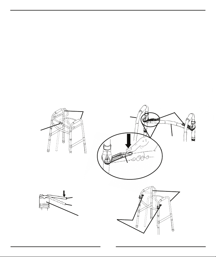
OPENING WALKERS (FIGURE 1)
NOTE: Refer to the FOLDING/ASSEMBLY WARNINGS in the SAFETY SUMMARY of
this manual.
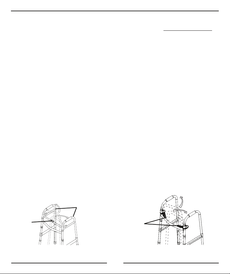
1. To OPEN the walker, pivot the left and right side frames outward.
2. Perform one (1) of the following:
SINGLE-RELEASE WALKER (6281) - Grip the side frames and
swing them fully outward while listening for an audible "click" which
indicates that the walker is fully opened and ready for test.
Refer to DETAIL "A" in FIGURE 1.
NOTE: The palm release button on the pivot slide tube will pop up when the click is heard.
BLUE-RELEASE WALKER (6241) - Swing the side frames outward
until an audible "click" is heard. Refer to DETAIL "B" in FIGURE 1.
PADDLE WALKER (6291) - Swing the side frames outward until
the dual-release paddles activate (engage upward).
Refer to DETAIL "C" in FIGURE 1.
3. Before using, test walker by grasping the side frames and, with some force,
attempt to fold them inward. See DETAIL "C" in FIGURE 1. The walker
will remain locked in the OPEN position if it is engaged properly. Test
Walker side frames before using. See DETAIL "D" in FIGURE 1.
DETAIL "A" DETAIL "B"
Palm
Release
Button
(“click”)
SINGLE-RELEASE
WALKER (6281)
Side Frames
Dual-Release
Mechanisms
6
WALKER (6241)
BLUE-RELEASE
DETAIL "C"
DETAIL "D"
Test Walker
Side Frames
Dual-Release
Paddles
LOCKED
UNLOCKED
Side
Frames
PADDLE
WALKER
(6291)
FIGURE 1 - OPENING WALKERS
FOLDING WALKERS (FIGURE 2)
NOTE: Refer to the FOLDING/ASSEMBLY WARNINGS in the SAFETY SUMMARY
of this instruction sheet.
1. Perform one (1) of the following to fold the walker:
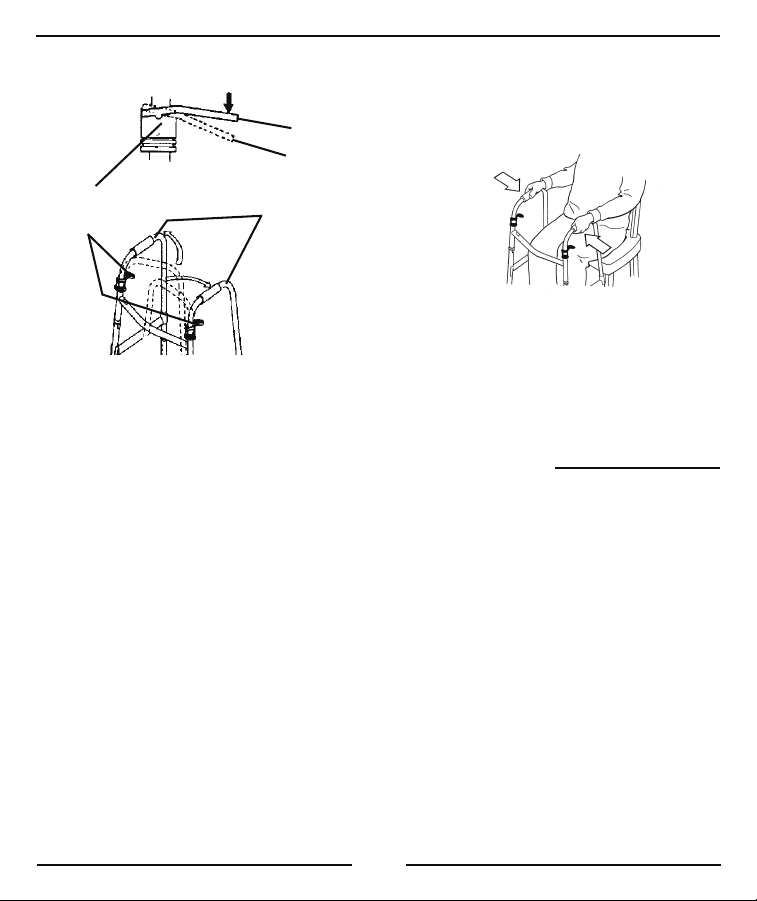
SINGLE-RELEASE WALKER (6281) A. Press DOWN on the palm release button located in the center
of the pivot slide tube. Refer to DETAIL "A" in FIGURE 2.
B. Pivot the right and left side frames inward until they meet the
front crossbrace.
BLUE-RELEASE WALKER (6241)
A. Depress either release mechanism and pivot the corresponding
side frame inward toward the front crossbrace. Refer to
DETAIL "B" in FIGURE 2.
B. Repeat the same procedure for the remaining side frame.
7
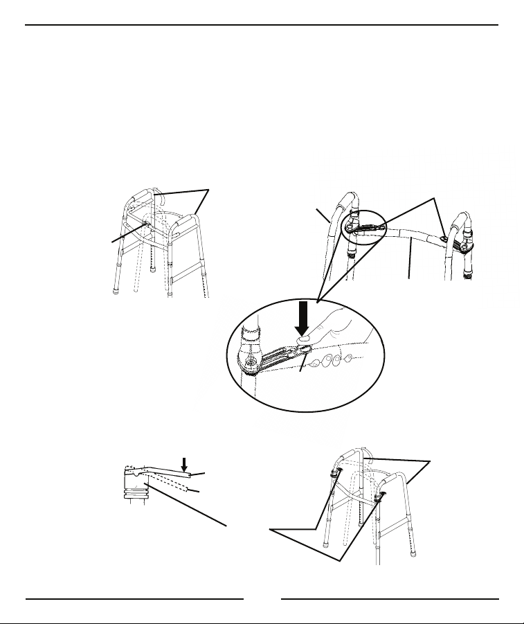
PADDLE WALKER (6291) -
A. Depress either release paddle and pivot the corresponding side
frame inward toward the front crossbrace. Refer to DETAIL
"C" in FIGURE 2.
B. Repeat the same procedure for the remaining side frame.
DETAIL "A"
Palm Release
Button (“click”)
SINGLE-RELEASE
WALKER (6281)
PADDLE
WALKER (6291)
Side
Frames
DETAIL "C"
LOCKED
UNLOCKED
Dual
Release
Paddles
DETAIL "B"
Side
Frame
Release
Mechanism
Dual-Release
Mechanisms
Front Crossbrace
BLUE-RELEASE
WALKER
(6241)
Side
Frames
FIGURE 2 - FOLDING WALKERS
8
INSTALLING/ADJUSTING LEG EXTENSIONS
(FIGURE 3)
NOTE: Refer to the INSTALLATION WARNINGS in the SAFETY SUMMARY of this
instruction sheet.
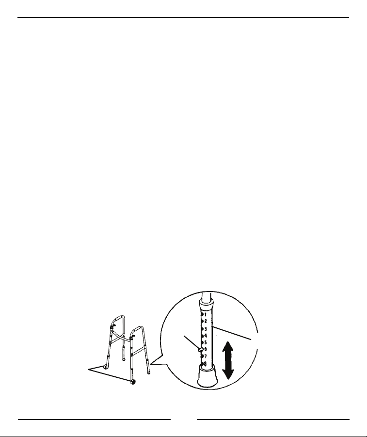
1. Remove leg extensions from carton and install the leg extensions by
depressing the snap buttons on the lower legs of the walker and
inserting the leg extension. Refer to FIGURE 3.
2. Depress the snap button and slide the leg up or down to the proper
height. Ensure that the snap button protrudes through the appropriate
adjustment hole on the leg extension.
NOTE: The leg extension adjustment holes are numbered for convenience.
3. Repeat this procedure for each leg extension.
4. Adjust leg extensions to ensure that the walker is LEVEL.
5. Adjust the walker so that when the user's
the handle is at wrist height.
NOTE: MODEL NO. 6291-3F, 6291-5F, 6291-JR3F, AND 6281-3F: Ensure that fixed
wheel attachments are positioned to the outside of the walker to help maintain stability.
Snap
Button
Fixed Wheel
Attachments
arm is extended downward
Leg Extension
NOTE: Model No.
6291-3F SHOWN
FIGURE 3 - INSTALLING/ADJUSTING LEG EXTENSIONS
9

CARE AND MAINTENANCE
1. Ensure that ALL attaching hardware is secure at ALL times.
2. Make sure Snap Buttons release and re-engage properly.
3. Replace any broken, damaged or worn items immediately.
CARE OF WHEELED ACCESSORIES
1. Clean wheels with warm water and mild cleanser. Dry with clean rag.
2. Lubricate with 3-in-1®oil periodically or if wheels begin to squeak.
LIFETIME LIMITED WARRANTY
Invacare warrants this product to be free from defects in materials and
workmanship.
PLEASE NOTE: THE WARRANTY BELOW HAS BEEN DRAFTED TO
COMPLY WITH FEDERAL LAW APPLICABLE TO PRODUCTS MANUFACTURED AFTER JULY 4, 1975.
This warranty is extended only to the original purchaser/user of our products.
This warranty gives you specific legal rights and you may also have other legal
rights which vary from state to state.
Invacare warrants its product to be free from defects in material and workman-
ship for the lifetime of use by original purchaser. If within such warranty period any
such product shall be proven to be defective, such product shall be repaired or
replaced, at Invacare’s option. This warranty does not include any labor or
shipping charges incurred in replacement part installation or repair of any such
product. Invacare’s sole obligation and your exclusive remedy under this warranty
shall be limited to such repair and/or replacement.
For warranty service, please contact the dealer from whom you purchased your
Invacare product. In the event you do not receive satisfactory warranty service,
please write directly to Invacare at the address on the back page. Provide dealer’s
name, address, model number, date of purchase, indicate nature of the defect and, if
the product is serialized, indicate the serial number.
10

LIFETIME LIMITED WARRANTY CONTINUED
Invacare Corporation will use a return authorization. The defective unit or parts
must be returned for warranty inspection using the serial number, when
applicable, as identification within thirty (30) days of return authorization
date. DO NOT return products to our factory without our prior consent.
C.O.D. shipments will be refused; please prepay shipping charges.
LIMITATIONS AND EXCLUSIONS: THE WARRANTY SHALL NOT APPLY
TO PROBLEMS ARISING FROM NORMAL WEAR OR FAILURE TO ADHERE TO THE ENCLOSED INSTRUCTIONS. IN ADDITION, THE FOREGOING WARRANTY SHALL NOT APPLY TO SERIAL NUMBERED PRODUCTS IF THE SERIAL NUMBER HAS BEEN REMOVED OR DEFACED;
PRODUCTS SUBJECTED TO NEGLIGENCE, ACCIDENT, IMPROPER
OPERATION, MAINTENANCE OR STORAGE; OR PRODUCTS MODIFIED
WITHOUT INVACARE’S EXPRESS WRITTEN CONSENT INCLUDING,
BUT NOT LIMITED TO: MODIFICATION THROUGH THE USE OF
UNAUTHORIZED PARTS OR ATTACHMENTS: PRODUCTS DAMAGED
BY REASON OF REPAIRS MADE TO ANY COMPONENT WITHOUT THE
SPECIFIC CONSENT OF INVACARE; PRODUCTS DAMAGED BY CIRCUMSTANCES BEYOND INVACARE’S CONTROL; PRODUCTS REPAIRED BY
ANYONE OTHER THAN AN INVACARE DEALER, SUCH EVALUATION
SHALL BE SOLELY DETERMINED BY INVACARE.
THE FOREGOING EXPRESS WARRANTY IS EXCLUSIVE AND IN LIEU OF
ALL OTHER EXPRESS WARRANTIES WHATSOEVER, WHETHER EXPRESS OR IMPLIED, INCLUDING THE IMPLIED WARRANTIES OF MERCHANTABILITY AND FITNESS FOR A PARTICULAR PURPOSE AND THE
SOLE REMEDY FOR VIOLATIONS OF ANY WARRANTY WHATSOEVER,
SHALL BE LIMITED TO REPAIR OR REPLACEMENT OF THE DEFECTIVE
PRODUCT PURSUANT TO THE TERMS CONTAINED HEREIN. THE
APPLICATION OF ANY IMPLIED WARRANTY WHATSOEVER SHALL
NOT EXTEND BEYOND THE DURATION OF THE EXPRESS WARRANTY
PROVIDED HEREIN. INVACARE SHALL NOT BE LIABLE FOR ANY CONSEQUENTIAL OR INCIDENTAL DAMAGES WHATSOEVER.
THIS WARRANTY SHALL BE EXTENDED TO COMPLY WITH STATE/
PROVINCIAL LAWS AND REQUIREMENTS.
11

Les marchettes Invacare ont une garantie à vie limitée (Se référer aux pages 10 et 11).
Les marchettes Invacare conviennent aux personnes pesant jusqu’à:
300 lbs. (136 kg.) - Modèles 6291-A, 6291-JR, 6291-1, 6291-3F, 6291-JR3F, 6291-5F,
6281-A, 6281-JR, 6281-3F, 6241-A, and 6241-JR
500 lbs. (226 kg.) - Modèles 6291-HDA
MARCHETTES À RELÂCHEMENT DOUBLE
•
Facile à ouvrir ou à fermer debout ou assis.
Largeur Profondeur
Modèle Entre Entre les Ouverte à la Pliée Réglage Taille du patient
No. les gaines pattes de la base base hauteur Min./Max.
6291-A 17po. 21-1/2po. 17-1/2po. 4po. 30-3/8po. - 37-3/8po. 5pi.3po. - 6pi.4po.
6291-JR 17po. 20-1/2po. 16-1/2po. 4po. 25-3/8po. - 32-3/8po. 4pi.4po. - 5pi.7po.
6241-A 17po. 19-1/2po. 17po. 4po. 30-3/8po. - 37-3/8po. 5pi.3po. - 6pi.4po.
6241-JR 17po. 18-1/2po. 16po. 4po. 25-3/8po. - 32-3/8po. 4pi.4po. - 5pi.7po.
MARCHETTES À RELÂCHEMENT DOUBLE AVEC ROUES FIXES
ET EMBOUTS PATINS
•
Les roues fixes de 3 ou 5 po. roulent librement sur les surfaces souples.
Largeur Profondeur
Modèle Entre Entre les Ouverte à la Pliée Réglage Taille du patient
No. les gaines pattes de la base base hauteur Min./Max.
6291-3F 17po. 21-1/4po. 17-1/2po. 4-1/2po. 31po. - 37po. 5pi.3po. - 6pi.4po.
6291-JR3F 17po. 20 -1/4po. 16 -1/2po. 4-1/2po. 26po. - 32po. 4pi.4po. - 5pi.7po.
6291-5F* 17po. 21-1/2po. 17-1/2po. 4-1/2po. 33po. - 39po. 5pi.3po. - 6pi.4po.
* avec des rallonges de pattes de 13 pouces
MARCHETTES À RELÂCHEMENT SIMPLE
•
Le bouton de déclenchement ergonomique permet de plier la marchette d'une seule main.
Largeur Profondeur
Modèle Entre Entre les Ouverte à la Pliée Réglage Taille du patient
No. les gaines pattes de la base base hauteur Min./Max.
6281-A 17po. 21-1/2po. 17-1/2po. 4-1/2po. 30-3/8po. - 37-3/8po. 5pi.3po. - 6pi.4po.
6281-JR 17po. 20-1/2po. 16-1/2po. 4-1/2po. 25-3/8po. - 32-3/8po. 4pi.4po. - 5pi. 7po.
12

MARCHETTE À RELÂCHEMENT SIMPLE AVEC ROUES FIXES ET
EMBOUTS PATINS
•
Les roues fixes de 3 po. roulent librement sur les surfaces souples.
Largeur Profondeur
Modèle Entre Entre les Ouverte à la Pliée Réglage Taille du patient
No. les gaines pattes de la base base hauteur Min./Max.
6281-3F 17po. 21-1/4po. 17-1/2po. 4po. 31po. - 37po. 5pi.3po. - 6pi.4po.
MARCHETTE ROBUSTE À DOUBLE RELÂCHEMENT POUR ADULTE
•
Les marchettes plus larges conviennent aux personnes pesant jusqu'à 500 livres.
Largeur Profondeur
Modèle Entre Entre les Ouverte à la Pliée Réglage Taille du patient
No. les gaines pattes de la base base hauteur Min./Max.
6291-HDA 20po. 24po. 17-1/2po. 4po. 30-3/8po. - 37-3/8po. 5pi. 3po. - 6pi.4po
Les spécifications peuvent être modifiées sans préavis
CONSERVEZ CES INSTRUCTIONS
NOTE: Vérifier TOUTES les pièces pour s’assurer qu’elles n’ont pas été endommagées pendant le transport.
Le cas échéant, NE PAS utiliser. Contacter le transporteur/fournisseur pour plus d’instructions.
RÉSUMÉ DES CONSIGNES DE SÉCURITÉ
Pour l'utilisation adéquate des marchettes Invacare, ces instructions
doivent être suivies:
AVERTISSEMENT GÉNÉRAL
NE PAS utiliser cet équipement sans d’abord avoir lu et
compris ce feuillet. Si vous ne comprenez pas les
avertissements, les notes attention et les instructions, veuillez
contacter un professionnel des soins de santé, un fournisseur ou
un technicien, avant d’installer cet équipement, sans quoi des
blessures ou des dommages peuvent survenir.
Chaque personne devrait toujours consulter son médecin ou son
thérapeute pour déterminer le réglage et l'utilisation adéquats.
Les produits Invacare sont spécifiquement conçus et fabriqués pour
être utilisés avec les accessoires Invacare. Les accessoires conçus
par d’autres manufacturiers n’ont pas été testés par Invacare et ne
doivent pas être utilisés avec les produits Invacare.
13

AVERTISSEMENTS POUR LA STABILITÉ
Si la marchette est exposée à des températures extrêmes (audessus de 100°F ou en dessous de 32°F), à une humidité élevée et/
ou si elle est mouillée, s’assurer, avant son utilisation, que les
poignées ne tournent pas sur le châssis latéral, sans quoi des
blessures ou des dommages peuvent survenir.
S'assurer que les embouts de caoutchouc et/ou les embouts patins en
plastique ne sont pas déchirés, usés ou manquants. Les remplacer
AVANT d'utiliser la marchette.
NE PAS utiliser d'embouts de caoutchouc sur les rallonges de pattes
arrière lorsque vous utilisez les options de roue avant ou de freins.
Les rallonges de pattes arrière avec embouts en caoutchouc ou
embouts patins en plastique DOIVENT être en contact avec la
surface du sol en tout temps.
Les embouts patins sont utilisés sur les rallonges de pattes arrière
SEULEMENT pour permettre à la marchette de rouler facilement sur
les moquettes sans avoir à soulever la marchette du sol.
Les embouts patins ne sont pas recommandés sur les surfaces
brutes (gravier, béton, etc).
Les embouts patins s sur les rallonges de pattes arrière devraient
être utilisé avec les attaches de roue avant seulement.
Les embouts patins ne sont pas recommandés pour l'extérieur.
Les embouts patins ne doivent pas être utilisés sur les quatre (4)
rallonges de patte à la fois.
NE PAS utiliser les embouts patins et les embouts de caoutchouc
en même temps.
Les embouts patins n'adhèrent pas à la surface du sol de la même
façon que les embouts de caoutchouc; il faut donc faire preuve de
prudence lors de l'utilisation.
Lorsque vous utilisez la marchette avec des embouts patins, faire de petits
pas pour s'assurer que le poids est distribué uniformément et directement
sur les pattes de la marchette. Ces précautions vous permettront
d'empêcher un mouvement non intentionnel de la marchette.
14

AVERTISSEMENTS POUR LA STABILITÉ (SUITE)
Toujours être prudent lorsque vous utilisez la marchette sur
une surface mouillée ou glacée.
Les marchettes Invacare peuvent procurer de l’aide
ambulatoire à des personnes pesant jusqu’à 300 livres (136 kg.)
pour les modèles simples (modèles 6281), Paddle (modèles
6291) et Blue-Release™(modèles 6241), et 500 lbs. (226 kg.) pour
la marchette robuste (modèle 6291-HDA).
Les marchettes Invacare sont conçues pour offrir support,
stabilité améliorée et aide aux personnes qui se déplacent en
marchant; elles ne sont pas conçues pour supporter le poids
total de l'utilisateur.
AVERTISSEMENTS POUR PLIER/ASSEMBLER
Une fois la marchette dépliée ou assemblée, s'assurer qu'elle est
bien bloquée en position OUVERTE et qu'elle est de niveau
avant de l'utiliser.
NE RIEN suspendre à l'avant de la marchette Blue-Release.
Ceci pourrait actionner les mécanismes de déclenchement et
empêcher la marchette de bloquer lorsqu'elle est
complètement ouverte.
NE PAS accrocher d'objets sur le châssis droit ou gauche
(incluant les leviers plats pour le double déclenchement) ou sur
les tubes droit ou gauche (incluant la région où est le bouton de
déclenchement pour la paume), car les châssis latéraux ou les
tubes pourraient plier vers le bas et empêcher la marchette de
bloquer en position ouverte. Ceci pourrait également faire
basculer la marchette et causer des blessures ou des dommages.
AVERTISSEMENTS POUR L'INSTALLATION
S'assurer que tous les boutons à ressort sont complètement
ressortis des orifices de montage des rallonges de pattes, pour
s'assurer qu'elles sont bien bloquées en place.
Les accessoires à roues, s'il y a lieu, doivent être utilisés SEULEMENT
sur les pattes avant, sauf pour les modèles 6264 - freins de roue
arrière 10 po. et modèle 6265 - freins de roue arrière 13 po.
15

AVERTISSEMENTS POUR L'INSTALLATION (SUITE)
Les rallonges de pattes doivent être réglées pour que la marchette
soit de niveau. Si vous ne pouvez obtenir une hauteur égale, régler
les rallonges de patte pour que l'arrière de la marchette n'ait pas
plus d'un pouce plus bas que l'avant de la marchette.
Toujours vérifier si la marchette et les attaches sont
sécuritairement et adéquatement bloquées AVANT l'utilisation.
OUVRIR LES MARCHETTES À DÉCLENCHEMENT
SIMPLE ET DOUBLE (FIGURE 1)
NOTE: Se référer aux AVERTISSEMENTS POUR PLIER/ASSEMBLER de la section
RÉSUMÉ DES CONSIGNES DE SÉCURITÉ de ce feuillet d'instructions.
1. Pour OUVRIR la marchette, tourner les châssis latéraux droit et
gauche vers l'extérieur.
2. Exécuter une des étapes suivantes:
MARCHETTE À DÉCLENCHEMENT SIMPLE(6281)- Saisir
les châssis latéraux et les ouvrir complètement jusqu'au déclic qui
confirme que la marchette est complètement ouverte et prête à
être utilisée. Se référer au SCHÉMA "A" de la FIGURE 1.
NOTE: Le bouton de déclenchement pour la paume situé sur le tube pivot coulissant
se relâchera au déclic.
BLUE-RELEASE MARCHETTE (6241) - Ouvrir les châssis latéraux
vers l'extérieur jusqu'au déclic. Se référer au SCHÉMA "B" de la FIGURE 1.
PADDLE MARCHETTE (6291) - Ouvrir les châssis latéraux
jusqu'à ce que les leviers plats à déclenchement double se relèvent
(bloqué vers le haut). Se référer au SCHÉMA "C" de la FIGURE 1.
3. Avant d'utiliser, vérifier si la marchette est bien ouverte en saisissant
les châssis latéraux et en forcant un peu pour tenter de la faire
refermer. La marchette demeurera bloquée en position OUVERTE si
elle est bien enclenchée. Tester les châssis latéraux avnat l'utilisation. Voir
SCHÉMA "D" de la FIGURE 1.
16

SCHÉMA "A"
Boutin de
déclenchement
pour la paume
("déclic")
MARCHETTE À DÉCLENCHEMENT
SIMPLE (6281)
Châssis
latéral
SCHÉMA "C" SCHÉMA "D"
SCHÉMA "B"
Mécanismes à
double
déclenchement
BLUE-RELEASE
MARCHETTE (6241)
Leviers plats à
double
déclenchement
BLOQUÉ
DÉBLOQUÉ
Châssis
latéral
PADDLE
(6291)
MARCHETTEMARCHETTE
MARCHETTE
MARCHETTEMARCHETTE
Vérifier les châssis
altéraux de la
marchette
FIGURE 1 - OUVRIR LES MARCHETTES
PLIER LES MARCHETTES (FIGURE 2)
NOTE: Se référer aux AVERTISSEMENTS POUR PLIER/ASSEMBLER du RÉSUMÉ
DES CONSIGNES DE SÉCURITÉ de ce feuillet d'instructions.
1. Exécuter une (1) des étapes suivantes pour plier la marchette:
MARCHETTES À DÉCLENCHEMENT SIMPLE A. APPUYER sur le bouton de déclenchement pour la paume situé au
centre du tube pivot coulissant. Se référer au SCHÉMA "A" de la
FIGURE 2.
B. Fermer les châssis latéraux droit et gauche jusqu'au croisillon.
17
BLUE-RELEASE MARCHETTE (6241)
A. Enfoncer un des mécanismes de déclenchement et faire pivoter
le châssis latéral correspondant vers l'intérieur et vers le
croisillon avant. Se référer au SCHÉMA "B" de la FIGURE 2.
B. Répéter la même procédure pour l'autre châssis latéral.
PADDLE MARCHETTE (6291) -
A. Enfoncer un des deux (2) leviers plats et faire pivoter le châssis
latéral correspondant vers l'intérieur jusqu'au croisillon.
B. Répéter la même procédure pour l'autre châssis latéral.
SCHÉMA "A"
Boutin de
déclenchement
pour la paume
("déclic")
MARCHETTE À
DÉCLENCHEMENT
SIMPLE (6281)
PADDLE
MARCHETTEMARCHETTE
MARCHETTE
MARCHETTEMARCHETTE
(6291)
SCHÉMA "B"
Châssis
latéraux
Châssis
latéral
Mécanisme de
déclenchement
Mécanismes à double
déclenchement
FCroisillon
avant
BLUE-RELEASE
MARCHETTEMARCHETTE
MARCHETTE
MARCHETTEMARCHETTE
SCHÉMA "C"
BLOQUÉ
DÉBLOQUÉ
Leviers plats à
double
déclenchement
FIGURE 2 - PLIER LES MARCHETTES
18
(6241)
Châssis
latéral

PLIER LES MARCHETTES À DÉCLENCHEMENT
SIMPLE ET DOUBLE (FIGURE 3)
NOTE: Se référer aux AVERTISSEMENTS POUR L'INSTALLATION du RÉSUMÉ
DES CONSIGNES DE SÉCURITÉ de ce feuillet d'instructions.
1. Sortir les rallonges de pattes de la boîte et les installer en enfonçant les
boutons à ressort des pattes inférieures de la marchette et en insérant les
rallonges. Se référer à la FIGURE 3.
2. Enfoncer le bouton à ressort et glisser la patte vers le haut ou vers le bas à
la bonne hauteur. S'assurer que le bouton à ressort ressort complètement
de l'orifice de réglage approprié sur la rallonge de la patte.
NOTE: Les orifices de réglage de la rallonge de la patte sont numérotés pour plus
de facilité.
3. Répéter cette procédure pour chaque rallonge.
4. Régler les rallonges de pattes pour s'assurer que la marchette est de NIVEAU.
5. Régler la marchette pour que la poignée soit à la hauteur du poignet de
l'utilisateur lorwque le bras est allongé vers l'avant.
NOTE: MODÈLES NO. 6291-3F, 6291-5F, 6291-JR3F ET 6281-3F: S'assurer que les
attaches des roues fixes sont placées à l'extérieur de la marchette pour aider à maintenir
la stabilité.
NOTE: Modèle
no. 6291-3F illustré
Bouton à
ressort
Attaches des
roues fixes
Rallonge de
patte
FIGURE 3 - INSTALLER/RÉGLER LES RALLONGES
DE PATTES
19

SOINS ET ENTRETIEN
1. S'assurer que TOUTE la quincaillerie de montage est TOUJOURS bien
serrée.
2. S'assurer que les boutons à ressort s'enfoncent et se relâchent
correctement.
3. Remplacer immédiatement tout accessoire brisé, endommagé ou usé.
SOINS DES ACCESSOIRES À ROUES
1. Nettoyer les roues avec de l'eau tiède et un nettoyant doux. Sécher
avec un chiffon propre.
2. Lubrifier périodiquement avec une huile 3-in-1®ou si les roues
commencent à grincer.
GARANTIE LIMITÉE À VIE
Invacare garantit ce produit contre tout défaut de fabrication ou défaut dans le
matériel.
REMARQUE: LA GARANTIE CI-DESSOUS A ÉTÉ RÉDIGÉE EN ACCORD AVEC
LA LOI FÉDÉRALE APPLICABLE SUR LES PRODUITS FABRIQUÉS APRÈS LE 4
JUILLET 1975.
Cette garantie est valable pour l'acheteur/utilisateur initial de nos produits seulement.
Cette garantie vous donne des droits légaux spécifiques. D'autres droits variant d'un
État à l'autre peuvent se rajouter.
INVACARE garantit ce produit à vie contre tout défaut de fabrication ou défaut dans le
matériel et ce, pour l'acheteur/utilisateur initial. Si, durant cette période, ce produit
devait s'avérer défectueux, ce dernier sera réparé ou remplacé, suivant le choix
d'INVACARE. Cette garantie ne comprend aucun frais de main-d'oeuvre ou d'envoi
relié au remplacement ou à la réparation de ce produit. La seule et unique obligation
d'INVACARE se limite au remplacement et/ou à la réparation du produit.
Pour le service, contacter le fournisseur qui vous a vendu le produit Invacare. Si vous
n'obtenez pas un service satisfaisant, écrire directement à INVACARE à l'adresse
indiquée ci-dessous. Fournir le nom du fournisseur, l'adresse, le numéro de modèle et
la date d'achat, indiquer la nature du problème et, si le produit comporte un numéro
de série, indiquer ce dernier.
20

GARANTIE LIMITÉE À VIE (SUITE)
Invacare émettra une autorisation de retour. L'unité ou les pièces défectueuses
doivent être retournées pour vérification de garantie, en indiquant le numéro de série,
s'il y a lieu, dans les trente (30) jours suivant la date de réception de l'autorisation de
retour. NE PAS retourner un produit à l'usine sans d'abord avoir obtenu notre
consentement. Les envois C.O.D. (payables sur réception) seront refusés. Veuillez
payer à l'avance les frais d'envoi.
LIMITATIONS ET EXCLUSIONS – LA PRÉSENTE GARANTIE NE S’APPLIQUE
PAS EN CAS DE PROBLÈMES DUS À UNE USURE NORMALE OU AU NON
RESPECT DES INSTRUCTIONS CI-JOINTE. DE PLUS, LA GARANTIE
ÉNONCÉE CI-DESSUS NE S’APPLIQUE PAS AUX PRODUITS AVEC NUMÉRO
DE SÉRIE EN CAS DE SUPPRESSION OU DE MAQUILLAGE DUDIT
NUMÉRO ; AUX PRODUITS AYANT ÉTÉ SOUMIS À UNE NÉGLIGENCE, À
UN ACCIDENT OU À UN USAGE, UN ENTRETIEN OU UN STOCKAGE
INCORRECTS ; NI AUX PRODUITS MODIFIÉS SANS LE CONSENTEMENT
EXPRÈS D’INVACARE, NOTAMMENT, MAIS DE FAÇON NON EXHAUSTIVE,
LA MODIFICATION RÉSULTANT DE L’UTILISATION DE PIÈCES OU
D’ACCESSOIRES NON AUTORISÉS ; LES PRODUITS ENDOMMAGÉS EN
RAISON DE RÉPARATION DE L’UNE DES PIÈCES EFFECTUÉE SANS LE
CONSENTEMENT SPÉCIFIQUE D’INVACARE ; LES PRODUITS
ENDOMMAGÉS PAR DES CIRCONSTANCES DÉPASSANT LE CONTRÔLE
D’INVACARE ; LES PRODUITS RÉPARÉS PAR TOUTE PERSONNE AUTRE
QU’UN REVENDEUR INVACARE. SEULE INVACARE POURRA PROCÉDER À
UNE TELLE ÉVALUATION.
LA GARANTIE EXPRESSE CI-DESSUS EST EXCLUSIVE ET REMPLACE
TOUTE AUTRE GARANTIE EXPRESSE QUELLE QU’ELLE SOIT, TACITE OU
EXPLICITE, Y COMPRIS LES GARANTIES TACITES DE QUALITÉ
MARCHANDE ET DE CONVENANCE POUR UN USAGE PARTICULIER. LE
SEUL RECOURS EN CAS DE VIOLATION DE TOUTE GARANTIE SE LIMITE À
LA RÉPARATION OU AU REMPLACEMENT DU PRODUIT DÉFECTUEUX
SELON LES TERMES ÉNONCÉS AUX PRÉSENTES. L’APPLICATION DE
TOUTE GARANTIE TACITE NE PEUT S’ÉTENDRE AU-DELÀ DE LA DURÉE
DE LA GARANTIE EXPRESSE INDIQUÉE AUX PRÉSENTES.
INVACARE NE PEUT ÊTRE TENUE POUR RESPONSABLE EN CAS DE
DOMMAGES INDIRECTS OU ACCESSOIRES, QUELS QU’ILS SOIENT. CETTE
GARANTIE PEUT ÊTRE ÉTENDUE AFIN DE RÉPONDRE AUX LOIS ET
RÉGLEMENTATIONS DES DIFFÉRENTS ÉTATS ET DIFFÉRENTES PROVINCES.
21

Los Andadores Invacare tienen una garantía limitada vitalicia (consulte las páginas 10 y 11).
Los Andadores Invacare pueden brindar asistencia a personas cuyo peso asciende hasta:
300 lbs. (136 kg.) - Modelos 6291-A, 6291-JR, 6291-1, 6291-3F, 6291-JR3F, 6291-5F,
6281-A, 6281-JR, 6281-3F, 6241-A, and 6241-JR
500 lbs. (226 kg.) - Modelos 6291-HDA
ANDADORES DE DESENGANCHE DOBLE
•
Fácil de abrir y cerrar, desde una posición sentado o de pie.
Ancho Profundidad
No. Interior, Interior, Abierto en Plegado Ajuste de Estatura del paciente
modelo agarraderas patas base la base la altura Mín./Máx.
6291-A 17" 21-1/2" 17-1/2" 4" 30-3/8" - 37-3/8" 5'3" - 6'4"
6291-JR 17" 20-1/2" 16-1/2" 4" 25-3/8" - 32-3/8" 4'4" - 5'7"
6241-A 17" 19-1/2" 17" 4" 30-3/8" - 37-3/8" 5'3" - 6'4"
6241-JR 17" 18-1/2" 16" 4" 25-3/8" - 32-3/8" 4'4" - 5'7"
ANDADORES DE DESENGANCHE DOBLE CON RUEDAS FIJAS
Y PUNTAS DESLIZABLES
•
Las ruedas fijas de 3 ó 5 pulgadas (8 ó 13 centímetros) ruedan libremente sobre superficies lisas.
Ancho Profundidad
No. Interior, Interior, Abierto en Plegado Ajuste de Estatura del
modelo agarraderas patas base la base la altura paciente Mín./Máx
6291-3F 17" 21-1/4" 17-1/2" 4-1/2" 31" - 37" 5'3" - 6'4"
6291-JR3F 17" 20-1/4" 16-1/2" 4-1/2" 26" - 32" 4'4" - 5'7"
6291-5F* 17" 21-1/2" 17-1/2" 4-1/2" 33" - 39" 5'3" - 6'4"
* patas con extensiones de 13 pulgadas (33 centímetros).
ANDADORES DE DESENGANCHE ÚNICO
•
El ergonómico botón de desenganche permite plegar el andador con una sola mano.
Ancho Profundidad
No. Interior, Interior, Abierto en Plegado Ajuste de Estatura del
modelo agarraderas patas base la base la altura paciente Mín./Máx.
6281-A 17" 21-1/2" 17-1/2" 4-1/2" 30-3/8" - 37-3/8" 5'3" - 6'4"
6281-JR 17" 20-1/2" 16-1/2" 4-1/2" 25-3/8" - 32-3/8" 4'4" - 5'7"
22

ANDADOR DE DESENGANCHE ÚNICO CON RUEDAS FIJAS Y
PUNTAS DESLIZABLES
•
Las ruedas fijas de 3 pulgadas (8 centímetros) ruedan libremente sobre superficies lisas.
Ancho Profundidad
No. Interior, Interior, Abierto en Plegado Ajuste de Estatura del paciente
modelo agarraderes patas base la base la altura Mín./Máx.
6281-3F1 7" 21-1/4" 17-1/2" 4" 31" - 37" 5'3" - 6'4"
ANDADOR DE DESENGANCHE DOBLE PARA ADULTOS, TRABAJO PESADO
•
Andador más ancho, brinda asistencia ambulatoria a personas cuyo peso asciende hasta 500 lbs. (226 kg.).
Ancho Profundidad
No. Interior, Interior, Abierto en Plegado Ajuste de Estatura del paciente
modelo agarraderes patas base la base la altura Mín./Máx.
6291-HDA 20" 24" 17-1/2" 4" 30-3/8" - 37-3/8" 5'3" - 6'4"
Las especificaciones están sujetas a cambio sin previo aviso.
CONSERVE ESTAS INSTRUCCIONES
NOTA: Revise todas las partes por si sufrieron daños durante el envío. Si así fuera,
NO use la unidad. Comuníquese con su distribuidor/empresa de transortes para
obtener mayores instrucciones.
RESUMEN DE SEGURIDAD
A fin de usar correctamente los Andadores Invacare, es FUNDAMENTAL
sequir las siguientes instrucciones:
ADVERTENCIAS GENERALES
Antes de instalar of usar este equipo, lea y comprenda
cabalmente estas instrucciones. Si no entiende las advertencias,
precauciones e instrucciones, comuníquese con un profesional
de la salud, su distribuidor o personal técnico antes de instalar el
equipo, de lo contrario podría sufrir lesiones o dañar el equipo.
Consulte a su médico o terapeuta para determinar el uso y los
ajustes adecuados de esta unidad.
Los productos Invacare están específicamente diseñados y
fabricados para ser usados conjuntamente con los accesorios
Invacare. Los accesorios diseñados por otros fabricantes no han
sido probados por Invacare y, por lo tanto, no se recomienda su
uso con los productos Invacare.
23

ADVERTENCIAS DE ESTABILIZACIÓN
Si se expone el andador a temperaturas extremas (superiores a 38°
C [100° F ] o inferiores a 0°C [32° F ]), a humedad excesiva y/o se
moja, antes de usarlo cerciórese de que las agarraderas no se
tuerzan en el bastidor lateral, de lo contrario usted podría sufrir
lesiones o dañar la unidad.
Cerciórese de que las puntas de goma y/o de plástico deslizables
no estén rotas, gastadas o falten. Reemplácelas ANTES de usar
el andador.
Ajuste todas las extensiones de las patas para que el andador quede
NIVELADO. Si va usar accesorios rodantes, AJUSTE las extensiones
de modo que los bastidores laterales queden nivelados.
NO use puntas de goma en las extensiones de las patas traseras
cuando use las opciones de rueda o freno en las patas delanteras.
Las extensiones de las patas traseras con puntas de goma o de
plástico deslizables DEBEN hacer contacto con el piso en todo
momento.
Las puntas deslizables se usan en las EXTENSIONES DE LAS PATAS
TRASERAS SÓLO para permitir que el andador ruede fácilmente
sobre áreas alfombradas sin que sea necesario levantar la unidad.
Las puntas deslizables sólo deben usarse con los accesorios
rodantes delanteros.
No use las puntas deslizables en superficies ásperas (asfalto,
ripio, etc.). El uso a la intemperie aumentará el desgaste de las
puntas deslizables.
No use al mismo tiempo las puntas deslizables en las cuatro (4)
extensiones de las patas.
NO use las puntas deslizables y de goma al mismo tiempo.
Las puntas deslizables no se adhieren al suelo como lo hacen las
puntas de goma; en consecuencia, tenga cuidado al usarlas.
Si va a usar puntas deslizables en el andador, dé pasos cortos para
distribuir uniformemente el peso y en forma directa sobre las
patas de la unidad. Estas precauciones evitarán el movimiento sin
control del andador.
24

ADVERTENCIAS DE ESTABILIZACIÓN (CONTINUACIÓN)
Siempre tenga cuidado al usar el andador en superficies
húmedas o escarchadas.
Los Andadores Invacare pueden brindar asistencia ambulatoria a
personas de distintos pesos. Los Andadores de Desenganche
Único (modelos 6281); de Paleta (modelos 6291) y Blue-Release™
(modelos 6241) hasta 300 lbs. (136 kg.); y el Andador para
Trabajo Pesado (modelo 6291-HDA) hasta 500 lbs. (226 kg.).
Los andadores Invacare han sido diseñados para proveer
apoyo, aumentar la estabilidad y brindar asistencia a la
persona mientras camina; no están diseñados para
soportar todo el peso del paciente.
ADVERTENCIAS DE PLEGADO/ENSAMBLADO
Después de sacar o ensamblar el andador, cerciórese de que la
unidad esté firmemente trabada en la posición OPEN (ABIERTA)
y a ras del suelo ANTES de usarla.
NO cuelgue nada delante del Andador de Desganche BlueRelease. Esto podría oprimir los mecanismos de
desenganche e impedir que la unidad se trabe en su lugar
completamente abierta.
NO cuelgue nada en los bastidores izquierdo o derecho
(zona que incluye las paletas de desenganche doble) o los
tubos deslizantes izquierdo y derecho (zona que incluye el
botón de desenganche manual). Ello hará que los bastidores
laterales o los tubos deslizantes se doblen hacia abajo e
impidan que el andador se trabe en su lugar al abrirse
totalmente. Ello también podría inclinar la unidad causando
lesiones al usuario o daños a la unidad.
ADVERTENCIAS DE INSTALACIÓN
Cerciórese de que todos los botones de cierre sobresalgan
totalmente a través de los orificios de ajuste en cada extensión
de las patas. De esta forma las extensiones quedarán firmemente
trabadas en su posición.
25

ADVERTENCIAS DE INSTALACIÓN (CONTINUACIÓN)
Los accesorios rodantes, si los hubiera, SÓLO deben usarse en las patas
delanteras del andador con excepción del modelo 6264 con frenos en la
rueda trasera de 10 pulgadas (25 centímetros) y el modelo 6265 con
frenos en la rueda trasera de 13 pulgadas (33 centímetros).
Ajuste las extensiones de las patas para que el andador quede
NIVELADO. Si no se puede obtener una altura nivelada, ajuste las
extensiones de las patas de modo que la parte posterior del andador no
quede más de 1 pulgada (3 centímetros) más abajo que la parte delantera.
Siempre cerciórese de que el andador y los accesorios queden
correcta y firmemente trabados en su lugar ANTES de usarlo.
CÓMO ABRIR LOS ANDADORES (FIGURA 1)
NOTA: Consulte la sección ADVERTENCIAS DE PLEGADO/ENSAMBLADO en el RESUMEN
DE SEGURIDAD de este manual.
1. Para ABRIR el andador, gire los bastidores izquierdo y derecho hacia afuera.
2. Realice (1) de los pasos siguientes:
ANDADOR DE DESENGANCHE ÚNICO (6281) - Tome los
bastidores laterales y muévalos totalmente hacia afuera hasta que se
oiga un chasquido, el cual indica que el andador está totalmente abierto
y listo para probarlo. Consulte el DETALLE "A", FIGURA 1.
NOTA: El botón de desenganche manual en el tubo deslizante subirá al oírse el chasquido.
DESGANCHE BLUE-RELEASE (6241) - Mueva los bastidores
laterales hacia afuera hasta que se oiga un chasquido. Consulte el
DETALLE "B", FIGURA 1.
ANDADOR DE PALETAS (6291) - Mueva los bastidores laterales
hacia afuera hasta que se activen las paletas de desenganche doble (se
enganchan hacia arriba). Consulte el DETALLE "C", FIGURA 1.
3. Pruebe el andador antes de usarlo; para ello, tome los bastidores laterales y,
aplicando un poco de fuerza, trate de doblarlos hacia adentro. Consulte el
DETALLE «C», FIGURA 1. Si está correctamente enganchado, el andador
permanecerá en la posición ABIERTA. Pruebe los bastidores laterales antes de
usar el andador. Consulte el DETALLE "D", FIGURA 1.
26

DETALLE "A" DETALLE "B"
Botón de
desenganche
manual
(chasquido)
Bastidores
laterales
Mecanismos
de desenganche
doble
ANDADOR DE DESENGANCHE
ÚNICO (6281)
DESENGANCHE
BLUE-RELEASE (6241)
DETALLE "C" DETALLE "D"
Pruebe los
bastidores laterales
del andador
Paletas de
desenganche
doble
TRABADO
DESTRABADO
Bastidores
laterales
ANDADOR DE
PALETAS
(6291)
FIGURA 1- CÓMO ABRIR LOS ANDADORES
CÓMO PLEGAR LOS ANDADORES (FIGURA 2)
NOTA: Consulte la sección ADVERTENCIAS DE PLEGADO/ENSAMBLADO en el
RESUMEN DE SEGURIDAD de esta hoja de instrucciones.
1. Realice (1) de los pasos siguientes para plegar el andador:
ANDADOR DE DESENGANCHE ÚNICO (6281)
A. PRESIONE el botón de desenganche manual situado en la parte
central del tubo deslizante. Consulte el DETALLE "A", FIGURA 2.
B. Gire los bastidores derecho e izquierdo hacia adentro hacia la
riostra delantera.
27

DESGANCHE BLUE-RELEASE (6241)
A. Presione cualquiera de los mecanismos de desenganche y gire el
bastidor lateral correspondiente hacia adentro, hacia la riostra
delantera. Consulte el DETALLE "B", FIGURA 2.
B. Repita el mismo procedimiento con el bastidor lateral restante.
ANDADOR DE PALETAS (6291)
A. Presione cualquiera de las paletas de desenganche y gire el bastidor
lateral correspondiente hacia adentro, hacia la riostra delantera.
Consulte el DETALLE "C", FIGURA 2.
B. Repita el mismo procedimiento con el bastidor lateral restante.
Botón de
desenganche
manual
(chasquido)
ANDADOR DE
DESENGANCHE
ÚNICO (6281)
ANDADOR DE
PALETAS (6291)
FIGURA 2 - CÓMO PLEGAR LOS ANDADORES
DETALLE "A"
Bastidores
laterales
Bastidor
lateral
Mecanismo
de desenganche
doble
DETALLE "C"
TRABADO
DESTRABADO
Paletas de
desenganche
doble
28
DETALLE "B"
Mecanismo de
desenganche manual
(chasquido)
Front
Crossbrace
DESENGANCHE
BLUE-RELEASE
(6241)
Bastidores
laterales

INSTALACIÓN/AJUSTE DE LAS EXTENSIONES DE LAS
PATAS (FIGURA 3)
NOTA: Consulte la sección ADVERTENCIAS DE INSTALACIÓN en el RESUMEN DE
SEGURIDAD de esta hoja de instrucciones.
1. Retire de la caja las extensiones de las patas e instálelas presionando los
botones de cierre en las patas inferiores del andador e insertando las
extensiones. Consulte la FIGURA 3.
2. Presione el botón de cierre y deslice la pata hacia arriba o abajo hasta la
altura deseada. Cerciórese de que el botón de cierre sobresalga totalmente
a través del orificio de ajuste correcto en la extensión de la pata.
NOTA: Los orificios de ajuste de la extensión de la pata vienen numerados.
3. Repita el procedimiento para cada extensión.
4. Ajuste las extensiones de las patas para que el andador quede NIVELADO.
5. Ajuste el andador de modo que cuando el usuario baje el brazo, la manija
quede a la altura de la muñeca.
NOTA: MODELOS 6291- 3F, 6291- 5F, 6291- JR3F, Y 6281- 3F: Cerciórese de
que los accesorios rodantes fijos estén situados hacia afuera del andador a fin de
mantener la estabilidad.
Botón
Accesorios
rodantes fijos
FIGURA 3 - INSTALACIÓN/AJUSTE DE LAS
Extensión de
la pata
NOTA: Se MUESTRA
el modelo 6291-3F
EXTENSIONES DE LAS PATAS
29

CUIDADO Y MANTENIMIENTO
1. SIEMPRE cerciórese de que TODOS los accesorios de conexión estén seguros.
2. Cerciórese de que los botones de cierre se desenganchen y reenganchen
adecuadamente.
3. Reemplace de inmediato toda parte dañada o desgastada.
CUIDADO DE LOS ACCESORIOS RODANTES
1. Limpie las ruedas con agua tibia y detergente suave. Séquelas con un
paño limpio.
2. Lubríquelas periódicamente con aceite 3-In-1â o si comienzan a chirriar.
GARANTÍA LIMITADA VITALICIA
Invacare garantiza que este producto no presenta defectos de material ni mano
de obra.
NOTA: LA SIGUIENTE GARANTÍA HA SIDO REDACTADA PARA
CUMPLIR CON LAS LEYES FEDERALESAPLICABLES A PRODUCTOS
FABRICADOS DESPUÉS DEL 4 DE JULIO DE 1975.
Esta garantía sólo es válida para el comprador/usuario original de nuestros
productos.
Esta garantía le otorga derechos específicos, y es posible que usted también tenga
otros derechos legales que pueden variar de una jurisdicción a otra.
Invacare garantiza al comprador original que este producto no presentará
defectos de material ni mano de obra durante su uso. Si durante este periodo
de vigencia de la garantía se demuestra que el producto presenta algún
defecto, Invacare, a su criterio, lo reparará o reemplazará. Esta garantía no
incluye los gastos por mano de obra ni envío en los cuales se incurra por la
instalación de los repuestos o la reparación del producto. La única obligación
de Invacare y la única solución para el comprador bajo esta garantía se
limitará a dichas reparaciones y/o reemplazo.
Para obtener el servicio de garantía, comuníquese con el distribuidor a quien
adquirió el producto Invacare. En caso de que usted no quede satisfecho con el
servicio de garantía, escríbanos directamente a Invacare a la dirección que
aparece en la próxima página. Indique el nombre y dirección del distribuidor, el
número de modelo y la fecha de compra del producto, señale la naturaleza del
defecto y adjunte el número de serie del producto si lo tuviera.
30

GARANTÍA LIMITADA VITALICIA (CONTINUACIÓN)
Invacare Corporation le asignará una autorización de devolución. Envíe la unidad
o las partes para ser revisadas adjuntando su número de serie, si corresponde,
como identificación dentro de treinta (30) días a partir de la fecha de
autorización de la devolución. NO devuelva el producto a la fábrica sin antes
contar con nuestra autorización. No se aceptan envíos con entrega contra
reembolso (C.O.D). Devuelva el producto con flete prepagado.
LÍMITES Y EXCLUSIONES: LA GARANTÍA NO SE APLICA A LOS
PROBLEMAS COMO RESULTADO DEL USO NORMAL, DESGASTE O POR
NO CUMPLIR CON LAS INSTRUCCIONES ADJUNTAS. ADEMÁS, LA
PRESENTE GARANTÍA, NO SE APLICARA A PRODUCTOS CUYO
NÚMERO DE SERIE HAYA SIDO REMOVIDO O MUTILADO,
PRODUCTOS QUE HAYAN SIDO SUJETOS A NEGLIGENCIA,
ACCIDENTE, O USO INDEBIDO, MANTENIMIENTO Y
ALMACENAMIENTO INAPROPIADOS, PRODUCTOS MODIFICADOS SIN
EL CONSENTIMIENTO EXPRESO Y POR ESCRITO DE INVACARE, EL
CUAL INCLUYE PERO NO SE LIMITA A: MODIFICACIONES MEDIANTE
EL USO DE PARTES O ACCESORIOS NO AUTORIZADOS: PRODUCTOS
DAÑADOS DEBIDO A REPARACIONES REALIZADAS A ALGUNO DE LOS
COMPONENTES SIN EL CONSENTIMIENTO ESPECÍFICO DE INVACARE,
PRODUCTOS DAÑADOS EN CIRCUNSTANCIAS FUERA DEL CONTROL
DE INVACARE, PRODUCTOS REPARADOS POR CUALQUIER OTRA
PERSONA QUE NO SEA PROVEEDOR DE INVACARE, ESTA GARANTÍA
EXPRESA ES EXCLUSIVA Y REEMPLAZA A TODAS LAS DEMÁS
GARANTÍAS SIN EXCEPCIÓN ALGUNA, YA SEAN ÉSTAS EXPRESAS O
IMPLÍCITAS, INCLUYENDO LAS GARANTÍAS IMPLÍCITAS DE
COMERCIABILIDAD E IDONEIDAD PARA UN FIN EN PARTICULAR Y LA
ÚNICA SOLUCIÓN POR EL INCUMPLIMIENTO DE CUALQUIER
GARANTÍA SE LIMITARÁ A LA REPARACIÓN O SUSTITUCIÓN DEL
PRODUCTO DEFECTUOSO, CONFORME A LOS TÉRMINOS AQUÍ
ESTABLECIDOS. ESTA GARANTÍA NO SE EXTENDERÁ MÁS ALLÁ DE LA
DURACIÓN DE ESTA GARANTÍA EXPRESA AQUÍ PROPORCIONADA Y
LA SOLUCIÓN A LAS VIOLACIONES A CUALQUIER GARANTÍA
IMPLÍCITA ESTARÁ LIMITADA A LA REPARACIÓN O REEMPLAZO DE
LOS PRODUCTOS DEFECTUOSOS DE ACUERDO CON LOS TÉRMINOS
AQUÍ PRESENTES. INVACARE NO SERÁ RESPONSABLE DE NINGÚN
DAÑO ACCIDENTAL O CONSECUENTE. ESTA GARANTÍA SE
EXTENDERÁ A FIN DE CUMPLIR CON LAS LEYES Y REQUERIMIENTOS
ESTATALES/ PROVINCIALES.
31

 Loading...