

IN USA IN2000-L2-LC Operating And Maintenance Instructions Manual
Date ECO# Rev Description Originator
DEC-98 1.0 FIRST RELEASE VJD
Mar-99 1.1 Hi-Lo Alarm Capability VJD
Sep-99 1.2 Flow rate for gas phase measurement VJD
Oct-00 172 A Release to Revision A CRH
Nov-00 189 B Updated Figure 4, Figure 7 LZ
OCT-26 311 C Add. Addendum #1069 (pages 29,30) LZ
TM
MODEL IN2000- L2-LC
LOW CONCENTRATION
OZONE ANALYZER
Operating and Maintenance Instructions
Title: Model IN2000-L2-LC Low Concentration Ozone Analyzer
Operating and Maintenance Instructions
Proprietary: The contents of t his docum ent are copyright protected.
© 1998 by IN USA, INC.
Doc.#:
610-0023-01
Page 1 of 30
Rev.:
C

CONFIGURATION
MODEL IN2000-L2-LC
SERIAL NUMBER
MEASURING RANGE
CPU REV
HVPS REV
PRE-AMP REV
KEYBOARD REV
SOFTWARE VERSION
CALIBRATION DATE/INITIALS
OPERATING MANUAL VERSION
TUBING TYPE:
AC VOLTAGE SERVICE:
CONFIGURATION:
INLET/OUTLET FITTINGS:
FACTORY INSTALLED OPTIONS:
TEFLON
STAINLESS STEEL
SPECIFIED VOLTAGE : ___________________
BENCH
RACK
NEMA 4X
Other ___________________________________
1/8" SWAGELOK™
1/4" SWAGELOK™
1/4" MALE VCR™
OTHER: _________________________________
SAMPLE PRESSURE COMPENSATION
SAMPLE TEMPERATURE COMPENSATION
Other _____________________________________
Title: Model IN2000-L2-LC Low Concentration Ozone Analyzer
Operating and Maintenance Instructions
Proprietary: The contents of t his docum ent are copyright protected.
© 1998 by IN USA, INC.
Doc.#:
610-0023-01
Rev.:
C
Page 2 of 30

TABLE OF CONTENTS
CONFIGURATION.......................................................................................................... 1
GENERAL SPECIFICATION...........................................................................................5
CAUTIONS AND GENERAL NOTES..............................................................................6
GENERAL DESCRIPTION..............................................................................................7
MECHANICAL INSTALLATION...................................................................................... 7
ELECTRICAL INSTALLATION ..................................................................................... 13
Power Connections................................................................................................................................................ 13
Signal Connections - Field Wiring....................................................................................................................... 13
SAMPLE GAS CONNECTIONS......................................................................................................................... 16
SETTING THE SAMPLE FLOW RATE......................................................................... 16
FRONT PANEL DESCRIPTION.................................................................................... 17
Digital Readout Description ................................................................................................................................. 18
Keyboard Description........................................................................................................................................... 18
REAR PANEL DESCRIPTION...................................................................................... 18
PREPARATION FOR OPERATION .............................................................................. 20
AC Input Voltage Selection .................................................................................................................................. 20
Initial Set Up.......................................................................................................................................................... 20
Turning the Unit On and Warming Up............................................................................................................... 20
Performing Lamp Calibration.............................................................................................................................. 21
PROGRAMMABLE PARAMETERS ............................................................................. 21
Description of Programmable Parameters .......................................................................................................... 21
Title: Model IN2000-L2-LC Low Concentration Ozone Analyzer
Operating and Maintenance Instructions
Proprietary: The contents of t his docum ent are copyright protected.
© 1998 by IN USA, INC.
Doc.#:
610-0023-01
Page 3 of 30
Rev.:
C

Alarm 1 and Alarm 2........................................................................................................................................... 22
Input/Output........................................................................................................................................................ 23
Operating Parameters.......................................................................................................................................... 23
Time and Date..................................................................................................................................................... 23
Programming Programmable Parameters.......................................................................................................... 23
WARNING/ERROR MESSAGES.................................................................................. 26
PERIODIC MAINTENANCE.......................................................................................... 27
Replacing the UV Lamp........................................................................................................................................ 27
ACCURACY AND CALIBRATION ................................................................................ 28
CONTACTING IN USA, INC. ........................................................................................ 28
Title: Model IN2000-L2-LC Low Concentration Ozone Analyzer
Operating and Maintenance Instructions
Proprietary: The contents of t his docum ent are copyright protected.
© 1998 by IN USA, INC.
Doc.#:
610-0023-01
Rev.:
C
Page 4 of 30

GENERAL SPECIFICATIONS
Measuring Principle Absolute determination by UV absorption. Automatic
zeroing.
Measuring Range
( Factory Set)
Display/Resolution
(a function of Measuring Range)
Sample Pressure and Temperature Optional
Linearity Better than 99% thro ughout range.
Calibration Standard Traceable to the US NIST, +/- 1%
Gas Phase: 0 - 9,999 PPMV, in multiple ranges
Dissolved O
Gas Phase: 0.001 PPMV or 0.1 PPMV
Dissolved O
: 0 - 3 mg/L, in multiple ranges
3
: 0.001 mg/L
3
Ozone Concentration Units
( Factory Set)
Readout 2x20 character, alpha-numeric, LCD.
Gas Sample Flow Rate Gas Phase: 1.0 l/min
Analog Outputs 4-20 mA and 0-10 V DC standard.
Digital Output RS-232 compatible interface, bi-directional.
Relay Contacts 3 Form C (Single Pole, Double Throw, Make before Break)
Diagnostic Features Continuous internal diagnostics with err or messaging and
Configurations 19" rack 3U height.
Sample Ports 1/4" Swagelok.
Supply Voltage 100/115 - 220/240 VAC, 50/60 Hz, Selectable
Environmental Operating Conditions 5-45°C; 0-95% RH noncondensing
Specifications subject to change without notice.
Gas Phase: PPMV (others upon special request).
Dissolved O
Dissolved O
rated at 5 Amp resistive load at 250 VAC.
instrument error relay.
NEMA 4X Wall Mounted
: mg/L (operated as part of a W-1 System)
3
: 1.0 l/min
3
Title: Model IN2000-L2-LC Low Concentration Ozone Analyzer
Operating and Maintenance Instructions
Proprietary: The contents of t his docum ent are copyright protected.
© 1998 by IN USA, INC.
Doc.#:
610-0023-01
Rev.:
C
Page 5 of 30

CAUTIONS AND GENERAL NOTES
CAUTION: HIGH CONCENTRATIONS OF OZONE ARE DANGEROUS AND HARMFUL TO
HUMANS. TAKE REASONABLE STEPS TO AVOID EXPOSURE. THE CURRENT MAXIMUM 8HOUR EXPOSURE LIMIT FOR OZONE IS 0.1 PPM.
NEVER LOOK DIRECTLY AT THE UV LAMP WHICH IS INSIDE THIS ANALYZER WITHOUT
PROPER EYE PROTECTION. UV RADIATION CAN CAUSE PERMANENT EYE DAMAGE.
COMPONENTS WITHIN THIS ANALYZER ARE POWERED BY AC. TAKE ALL NECESSARY
PRECAUTIONS TO ELIMINATE THE RISK OF ELECTRICAL SHOCKS.
CERTAIN COMPONENTS MAY BE HOT TO THE TOUCH. PLEASE ALLOW PROPER COOLING
TIME BEFORE WORKING WITH THESE COMPONENTS.
AFX®, IN USA™, and Excellence in Instrumentation™ are trademarks of IN USA, INCORPORATED.
This document is copyright protected.
IN USA™, INC. reserves the right to make changes to the product covered in this manual to improve
performance, reliability, or manufacturability. Make sure that this manual is used with the original product
it was shipped with.
Although every effort has been made to ensure accuracy of the information contained in this manual, IN
USA™ assumes no responsibility for inadvertent errors.
IN USA™ assumes no responsibility for the use of any measuring schemes described herein.
This product is not intended, or recommended by IN USA
therapy of any kind, whether as a direct or adjunct part of such therapy, including, without limitation, life
support (i.e., critical medical) applications or (b) any nuclear facility applications.
IN USA™ will not knowingly sell this product for use in such applications. Use of the IN USA™ product
in connection with medical or like treatment cannot be reasonably expected to produce accurate monitorings
of therapy or treatment, and may cause failure of the life-support device or significantly affect its safety or
effectiveness. Use by any direct purchaser or after-market purchaser in such applications whether or not
known to IN USA™ shall absolve IN USA™ of any responsibility or liability to such purchaser(s) or to any
person(s) subjected to or affected by such use knowingly or unknowingly.
TM
for use in (a) medical therapy or physical
Title: Model IN2000-L2-LC Low Concentration Ozone Analyzer
Operating and Maintenance Instructions
Proprietary: The contents of t his docum ent are copyright protected.
© 1998 by IN USA, INC.
Doc.#:
610-0023-01
Rev.:
C
Page 6 of 30

GENERAL DESCRIPTION
The L2-LC Ozone Analyzer is an ultraviolet (UV) absorption analyzer designed for the monitoring of low
concentrations of ozone in the gaseous phase. If so equipped, the analyzer also allows the user to monitor
the pressure and temperature of the ozone in the measurement cell.
MECHANICAL INSTALLATI ON
The L2-LC can be housed for bench top, 19" rack and wall mounting. Figure 1 and Figure 2 provide
mechanical dimensions for bench top and for 19" rack mounting.. The instrument should be used in areas
where the operating conditions are within the envelope defined under General Specifications, and where
free air circulation is provided for convection cooling.
Note
: If the analyzer is rack mounted, it should either have side rails or be supported in the back to
reduce stress on the front panel. The front panel mounting “ears” are not robust enough to support the
weight of the unit.
Figure 3 provides mechanical dimensions for the NEMA 4X enclosure.
Title: Model IN2000-L2-LC Low Concentration Ozone Analyzer
Operating and Maintenance Instructions
Proprietary: The contents of t his docum ent are copyright protected.
© 1998 by IN USA, INC.
Doc.#:
610-0023-01
Rev.:
C
Page 7 of 30
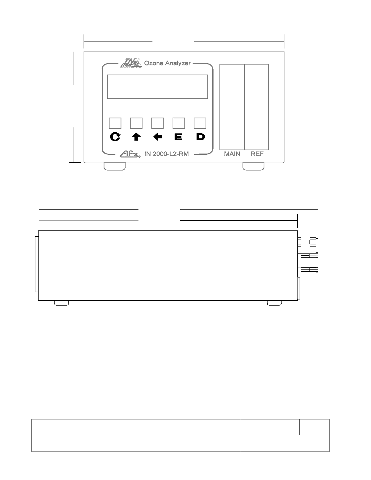
5.60 [142MM]
]
]
Figure 1: Bench Top Dimensions
8.50 [216MM]
18.18 [481MM
16.85 [428MM
Title: Model IN2000-L2-LC Low Concentration Ozone Analyzer
Operating and Maintenance Instructions
Proprietary: The contents of t his docum ent are copyright protected.
© 1998 by IN USA, INC.
Doc.#:
610-0023-01
Rev.:
C
Page 8 of 30
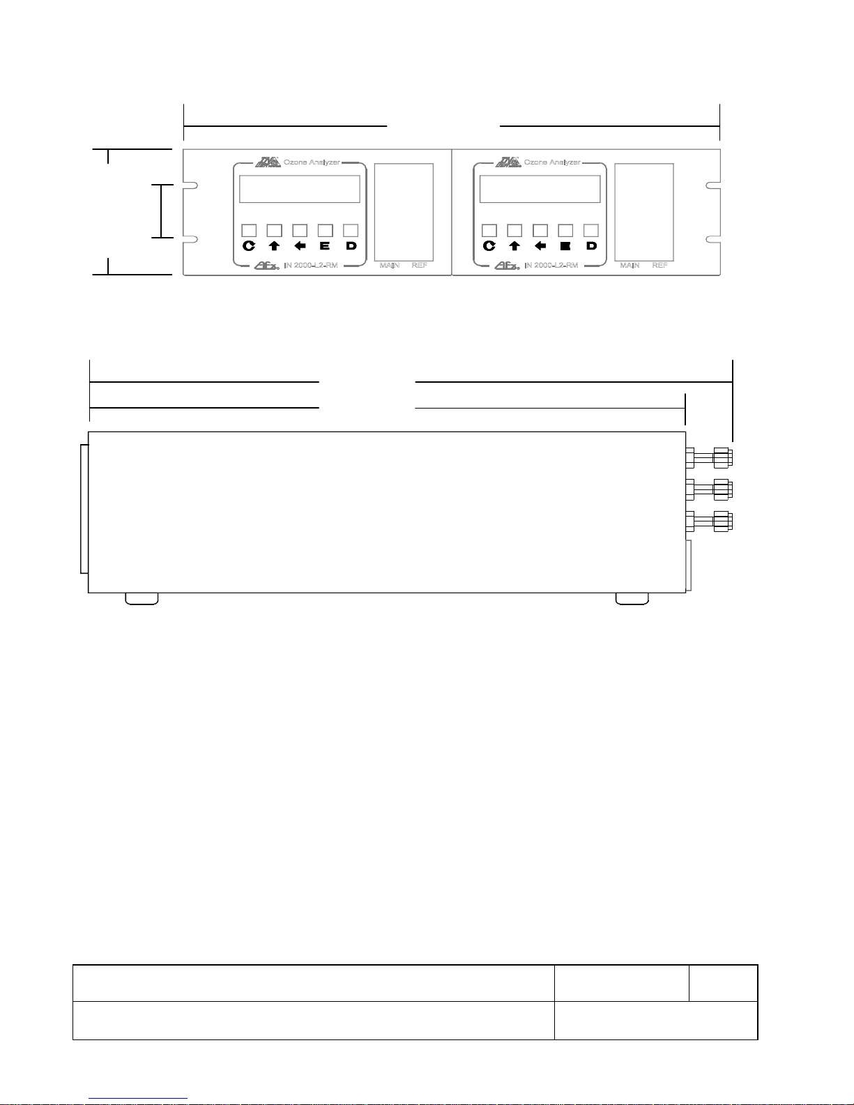
Figure 2: 19" Rack Dimensions
19.00 [483MM]
2.25 [57MM]
5.25 [133MM]
18.18 [481MM]
16.85 [428MM]
Title: Model IN2000-L2-LC Low Concentration Ozone Analyzer
Operating and Maintenance Instructions
Proprietary: The contents of t his docum ent are copyright protected.
© 1998 by IN USA, INC.
Doc.#:
610-0023-01
Rev.:
C
Page 9 of 30
 Loading...