

GeoStamp+®with GPS
GPS on-screen composite video overlay
Version 1.0
Copyright © 2010 Intuitive Circuits, LLC

escription
D
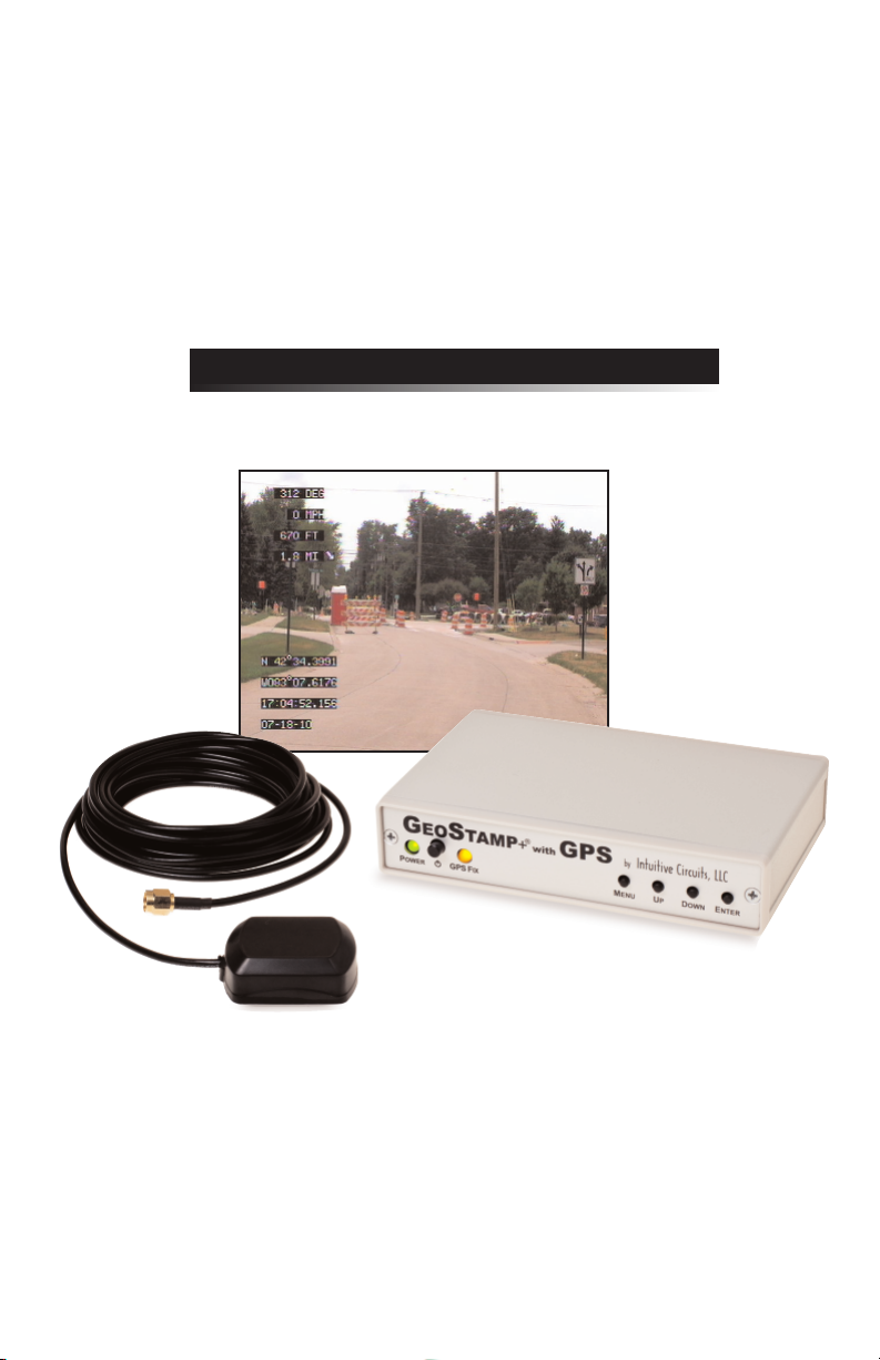
GeoStamp+®with GPS is an on-screen composite video overlay device that overlays
GPS (Global Positioning System) latitude, longitude, heading (track), speed, altitude,
date, and time onto any incoming NTSC or PAL composite video source such as a
color video camera. In addition to displaying GPS information, GeoStamp+®with
GPS can also display a user defined message as well as real-time distance and bearing
to a user defined waypoint. GeoStamp+®with GPS produces a self-generated screen
if no video input source is available. GeoStamp+®with GPS includes a high precision
internal GPS receiver and an external antenna.
pecifications
S
Dimensions: 5 1/2" x 3 1/2" x 1 1/4"
Weight: 9.3 oz.
RoHS compliant: Yes
Input voltage: 7.0 to 14.0 volts DC (210 ma max.)
DC plug: 2.1 mm x 5.5 mm, center tip positive
Operating temperature: -40C to +85C (extended temperature range standard)
Video format: Composite video
Video level: 1 volt peak to peak
Video impedance: Input 75 ohm, output 75 ohm resistively terminated
Speed format: MPH, KPH, and knots
Altitude format: Feet and meters
Heading (track) format: Compass cardinal points (e.g. NW) and degrees
Time format: UTC with user time zone adjustment
Date format: mm/dd/yy and dd/mm/yy
User custom message length: 10 characters
2
nternal GPS Receiver Secifications
I
Receiver: L1 C/A code, 65-channel
Position Accuracy: 2.5 meters CEP
Velocity Accuracy: 0.1 meters/sec
Time Accuracy: 300ns
Startup Time: 29 second warm/cold start under open sky (average)
Sensitivity: -161dBm tracking
Update Rate: 1, 2, 4, 5 Hz (1 Hz default)
Dynamics: 4G (39.2m/sec2)
Operational Limits: Altitude < 18,000 meters and velocity < 515
meters/sec (simultaneously)
External Antenna: Active, 3.3 or 5.0 Volts DC with gain up to 30dB and
noise figure less than 2db
onnections
C
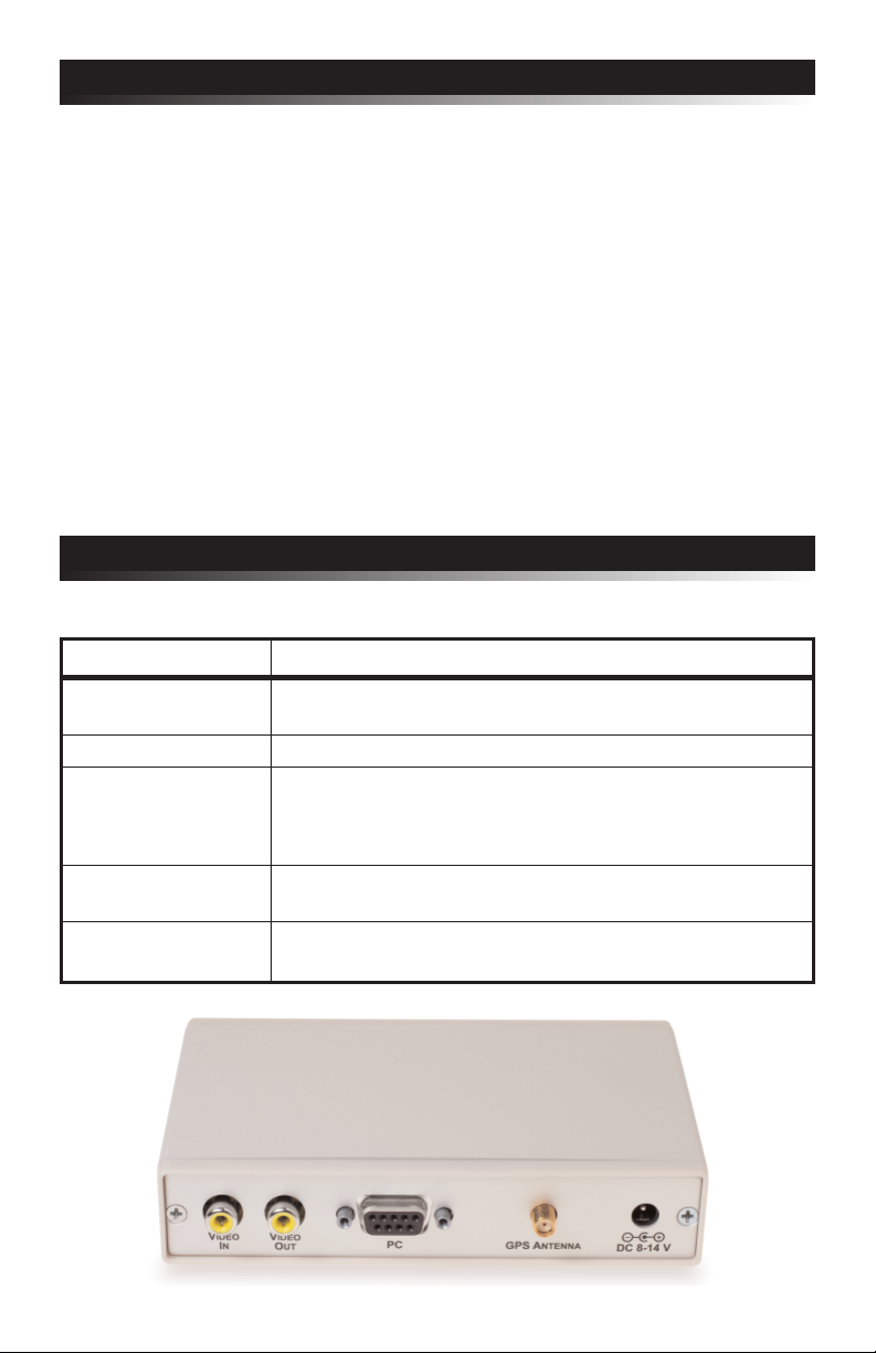
GeoStamp+®with GPS has five connectors (see figure 1).
Connector Hookup
VIDEO IN (optional) • Attach noise free NTSC or PAL composite video source
• Leave disconnected for self-generated video output
VIDEO OUT • Attach to video monitor, DVR, video transmitter, etc.
PC • Attach to PC using male to female DB-9 serial cable
• Pin 2 - Serial out (from GeoStamp+
• Pin 3 - Serial in (to GeoStamp+®with GPS)
• Pin 5 - Ground
GPS ANTENNA • Attach to GPS antenna with SMA male connector
• 3.3 or 5.0 Volts DC antenna only
DC IN • +7.0 to +14 volts DC
• 2.1 mm x 5.5 mm DC coax plug, center tip positive
®
with GPS)
figure 1
3

IP Switch Configuration
D
GeoStamp+®with GPS comes configured for NTSC video format and a 1 Hz (once
per second) GPS update rate. To reconfigure these settings GeoStamp+®with GPS
has 4 internal dip switches. To access the dip switches disconnect all cables from
®
the GeoStamp+
enclosure. After removing the rear panel and bezel the circuit board will slide out.
with GPS unit then remove the 2 screws from the rear of the
DIP # Description
1 & 2 GPS RS-232 update rate
DIP 1 DIP 2 Rate
OFF OFF 1 Hz
OFF ON 2 Hz
ON OFF 4 Hz
ON ON 5 Hz
3 NTSC or PAL video format
OFF = NTSC
ON = PAL
4 Firmware flash update
OFF = Normal operation
ON = Firmware flash mode
Note: DIP switch inputs are only checked during power-up.
n-Screen Menu Configuration
O
At any time press the "MENU" button to enter the on-screen menu configuration.
The "UP", "DOWN", and "ENTER" buttons move the cursor and change the
settings. All configuration information is stored in non-volatile memory so
information is retained even with loss of power to the GeoStamp+®with GPS unit.
Main Menu:
Menu Option Action / Setting
Enable GPS Overlay • ON - Display the overlay text
• OFF - Pass video through without displaying the
overlay text
Display Options Menu... Display the Options Menu
Field Formatting Menu...
Save Changes and Exit Save changes and exit the Main Menu
Discard Changes and Exit
4
Display the Field Formatting Menu
Discard changes and exit the Main Menu

Display Options Menu:
Menu Option Action / Setting
Screen Layout Select an on-screen GPS field layout format
• Standard - Fields are displayed on the top and bottom
of the screen
• Top - Fields are displayed on the top of the screen
• Bottom - Fields are displayed on the bottom of the screen
• Left - Fields are displayed on the left side of the screen
• Right - Fields are displayed on the right side of the screen
• Custom - Field layout is configured via gsLayout+ application
Backgnd Frame • ON - Draw a background frame behind the overlay text
• OFF - Do not draw a background frame behind the overlay text
Show Status • ON - Display the GPS receiver status on-screen
• OFF - Do not display the GPS receiver status on-screen
Show Altitude • ON - Display altitude on-screen
• OFF - Do not display altitude on-screen
Show Ranging • ON - Display distance and bearing to waypoint on-screen
• OFF - Do not display distance and bearing to waypoint on-screen
Show User Msg • ON - Display the user defined message on-screen
• OFF - Do not display the user defined message on-screen
User Message Enter an optional 10 character on-screen message
• MENU button to decrement cursor position
• ENTER button to increment cursor position
• UP / DOWN buttons to cycle through characters
Download Download a custom field layout via the gsLayout+ application
Custom Layout...
Main Menu Return to Main Menu
Field Formatting Menu:
Menu Option Action / Setting
Altitude • Meters
• Feet
Speed • Knots
• KPH
• MPH
Heading • Degrees (e.g. 90)
• Compass (e.g. NW)
Ranging • Meters
• Feet
mm-dd-yy
Date
UTC Of
Main Menu Return to Main Menu
fset Time offset from UTC (-12 through +12) e.g. -5 is EDT
•
dd-mm-yy
•
ENTER button to increment value
•
5

gsLayout+ GPS Field Layout Utility
In addition to the GeoStamp+®with GPS built-in on-screen GPS field layout
formats (e.g. standard, top, etc) custom GPS field layout screens can be created
using gsLayout+, a powerful Windows PC based GPS field layout utility.
The gsLayout+ utility manages positioning and formatting of all the on-screen
GPS fields. The user configurable information is uploaded from the PC to the
GeoStamp+®with GPS unit via an RS-232 serial cable. All uploaded information
is stored in the GeoStamp+®with GPS device's non-volatile memory.
gsLayout+ system requirements: Microsoft Windows 2000 operating system or
later with minimum 1024 x 768 video screen resolution and one RS-232 serial port
(or USB to RS-232 converter).
To install gsLayout+ insert the Intuitive Circuits Utilities disc and run setup.exe
located in the gsLayout+ folder. Follow the installation instructions.
To download gsLayout+ go to the Intuitive Circuits secure download page at
http://www.icircuits.com/store/downloads_secure.php
Login: (Contact Intuitive Circuits)
Password: (Contact Intuitive Circuits)
Download the gsLayout+.zip file, unzip the file into a temporary folder and run
setup.exe. Follow the installation instructions. After the installation is complete the
temporary folder can be removed.
The gsLayout+ program shortcut is located on the computer desktop and in the
Start>>Programs>>Intuitive Circuits folder.
figure 2
6

peration
O
After power is applied GeoStamp+®with GPS performs the following operations:
1. Establish communications with the internal GPS receiver
2. Wait for the GPS receiver fix with a minimum of 4 satellites
3. Update the on-screen fields after each valid NMEA GPRMC and GPGGA
sentence is received from the internal GPS receiver
4. Check for "MENU", "UP", and "DOWN" button presses
At any time press the "MENU" button to enter the on-screen menu configuration.
Status Icon:
If the "Show Status" option is enabled (by default) the following icons may appear:
Icon Status
No or invalid communications with the internal GPS receiver
The internal GPS receiver does not have a satellite fix
"GPS FIX" LED:
The "GPS Fix" LED illuminates when the internal GPS receiver has a fix with a
minimum of 4 satellites. A GPS fix is required for on-screen GPS information to update.
Distance and Bearing to Waypoint:
If the "Show Ranging" option is enabled then real-time distance and bearing
information from the current location to the user defined waypoint is displayed in
real-time.
At any time while there is a GPS fix press the "UP" button to set the current
location as the waypoint. Pressing the "DOWN" button will clear the waypoint.
It is not necessary to clear the waypoint before setting it again.
7

rouble Shooting Tips
T
Problem
Green Power LED will not illuminate
GeoStamp+®with GPS
turn on
Blinking Clock icon
No GPS information on-screen
or fields do not update
Blinking Satellite Dish icon
Yellow "GPS FIX" LED off
No GPS information on-screen
or fields do not update
On-screen text is difficult to read
arranty & Service
W
will not
Solution
• Verify power supply output (7.0 to 14 volts DC)
• Verify polarity of supply to GeoStamp+® with GPS
• Verify internal fuse is good.
• No valid communications with the internal
GPS receiver
• Verify external GPS antenna attached
• The internal GPS receiver does not have a
satellite fix
• Verify external GPS antenna attached
• Verify a clear view to the sky
• Wait up to 4 minutes for initial GPS receiver fix
• Verify that the GeoStamp+®with GPS
"VIDEO IN" has a noise free video signal
• Enable the Background Frame in the Display
Options Menu
If the product fails to perform as described in our product description or specification,
within 1 year from the date of shipment to the buyer, we will repair or replace the
product and/or accessories originally supplied. Failure due to improper installation,
misuse, abuse or accident is not covered by this warranty. Incidental and consequential
damages are not covered by this warranty. The buyer must first obtain a Return
Material Authorization number by calling (248) 588-4400, or send email to
support@icircuits.com. Ship the defective product (with RMA number) to
Intuitive Circuits, 3928 Wardlow Ct., Troy, MI 48083, freight prepaid.
Intuitive Circuits, LLC
3928 Wardlow Ct.
, MI 48083
roy
T
Voice: (248) 588-4400
Fax: (248) 588-4455
http://www.icircuits.com
 Loading...