

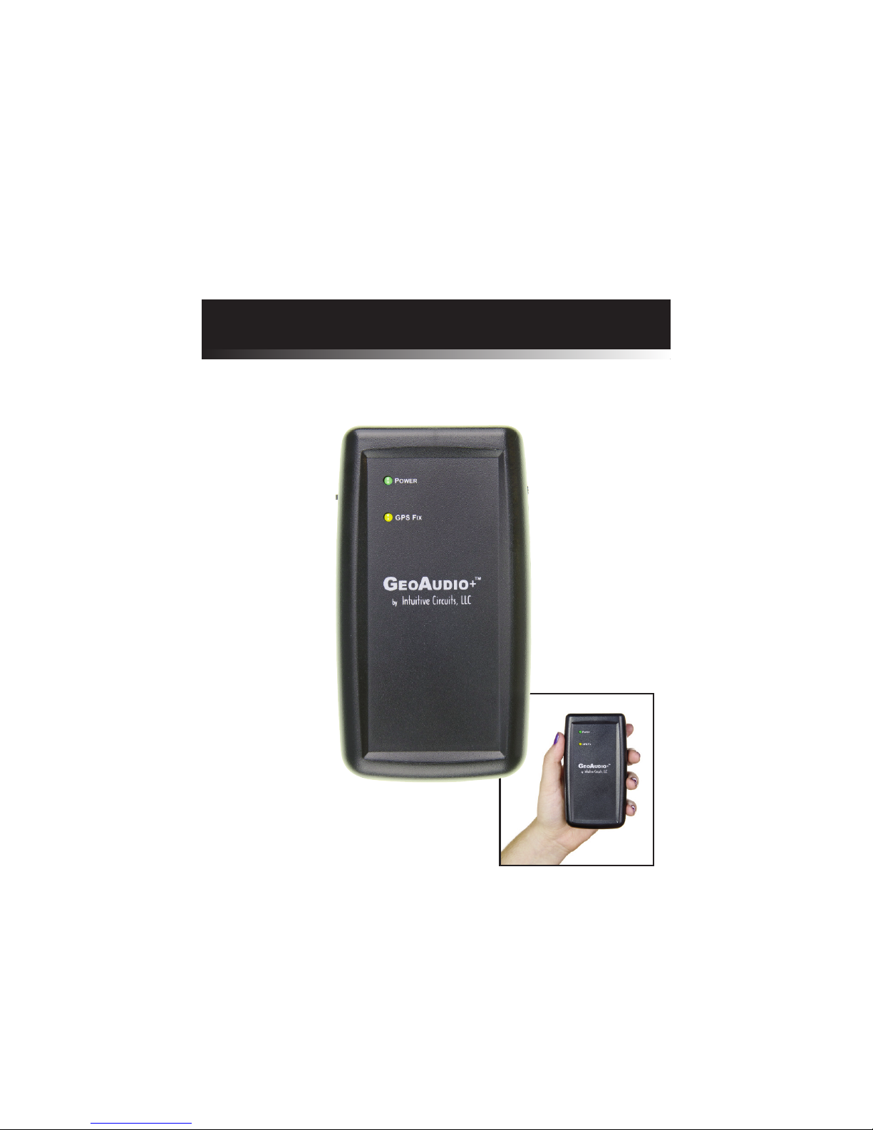
GeoAudio+
Copyright © 2012 Intuitive Circuits, LLC
Version 1.00
Portable GPS to Audio Encoder / Decoder
with Internal High Precision GPS Receiver and Antenna

D
escription
GeoAudio+ with built-in GPS receiver encodes GPS location, heading, speed, altitude,
date, and time into a continuous audio stream that can be recorded by off-the-shelf
camcorders and DVR (digital video recorder) systems. The encoded audio, automatically
synchronized with the camera video, translates into an exact, permanent record of when
and where the events in the video occurred.
GeoAudio+ decode mode is used during the video playback to convert the encoded audio
back into a GPS NMEA 0183 USB serial stream that can be used by most PC mapping
applications such as Google Earth.
GeoAudio+ includes a 6’ 3.5 mm male-to-male audio cable, 6’ USB A-Male to Mini-B cable,
Microsoft Windows USB driver and diagnostic application disc. 4 AAbatteries are not included.
S
pecifications
Dimensions: 4.25" x 3.50" x 1.25"
Weight: Without Batteries: 3.9 oz., with 4 AA Batteries: 7.3 oz.
Input Voltage: 5.0 VDC via USB connector, 6.0 VDC via 4 AA batteries
Operating Temperature: -40 C to +85 C
Audio Modulation: FSK
Audio Output Level: -10dB +/- 1dB
Audio Input Level Range: -40.0 to -8.0 dBV
Acceptable Audio Signal to
Noise Ratio:
20.0 dB
Audio In/Out 3.5mm Stereo Jack:
TIP - Left audio channel, RING 1- Right audio channel
RING 2 - Ground
USB Jack: Mini-B
2
I
nternal GPS Receiver Specifications
Receiver: L1 C/A code, 65-channel
Position Accuracy: 2.5 meters CEP
Velocity Accuracy: 0.1 meters/sec
Time Accuracy: 300ns
Startup Time: 29 second warm/cold start under open sky (average)
Sensitivity: -161dBm tracking
NMEA sentences: GPRMC and GPGGA
Update Rate: 1 Hz (once per second)
Dynamics: 4G (39.2m/sec2)
Operational Limits:
Altitude < 18,000 meters and velocity < 515 meters/sec (simultaneously)
GeoAudio+ includes an internal GPS antenna. An external GPS antenna version of the
product is also available.
External Antenna (optional): Active, 3.3 or 5.0 Volts DC with gain up to 30dB and noise
figure less than 2db. Male SMA connector.
3
G
eoAudio+ Configuration
GeoAudio+ has an internal 4 dip switch configuration, audio channel selector jumper, and
encoding audio output level adjustment. GeoAudio+ comes preconfigured for normal
operation. No additional configuration changes are required.
To reconfigure the GeoAudio+standard configuration disconnect all power to the unit.Carefully
remove the 4 case screws (two of the screws are accessible after removing the battery cover).
Carefully pull the top and bottom of the case apart so not to put strain on the battery wires.
Dip Switch Configuration:
DIP # Description
1 USB Baud Rate:
OFF = 4,800 baud (default)
ON = 9,600 baud
2 Diagnostic Mode:
OFF = Normal operation (default)
ON = Generate 100 lines of test FSK audio data
3 Raw Debug Mode:
OFF = Normal operation (default)
ON = GPS NMEA data sent directly out USB port instead of
FSK encoding
4 Firmware Flash Upgrade:
OFF = Normal operation (default)
ON = Firmware flash mode
Note: DIP switch inputs are only checked during power-up.
Audio Channel Selector Jumper:
JP1 Description
L Audio encoded/decoded on left channel (default)
R Audio encoded/decoded on right channel
Encoding Audio Output Level Adjustment:
The encoded audio output level of GeoAudio+ can be adjusted via the output level
potentiometer VR1. GeoAudio+ supports microphone to line level output. (Tick #5 of
#11 is default.)
G
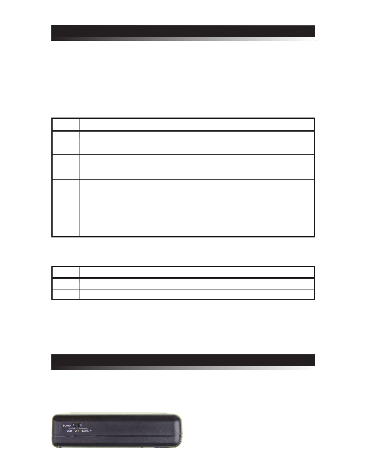
eoAudio+ Power
GeoAudio+ can be powered by internal 4 AA batteries or external USB source. The AA
batteries can be installed even when a USB power source is supplied. Move the POWER
switch to the desired position. (See Figure 1.0) The green POWER LED on the top of
the case will turn on once power is applied.
Figure 1.0 – Power selection switch
4
G
eoAudio+ Cable Hookup and Operation
GeoAudio+ has two operating modes Encode and Decode:
• Encode mode is used during the video recording process to encode the GPS
information onto the camcorder or DVR (digital video recorder) left or right
audio track
• Decode mode is used during the video playback to convert the encoded audio back
into a GPS NMEA serial stream that GPS mapping software recognizes. During
decode mode the yellow GPS Fix LED will blink.
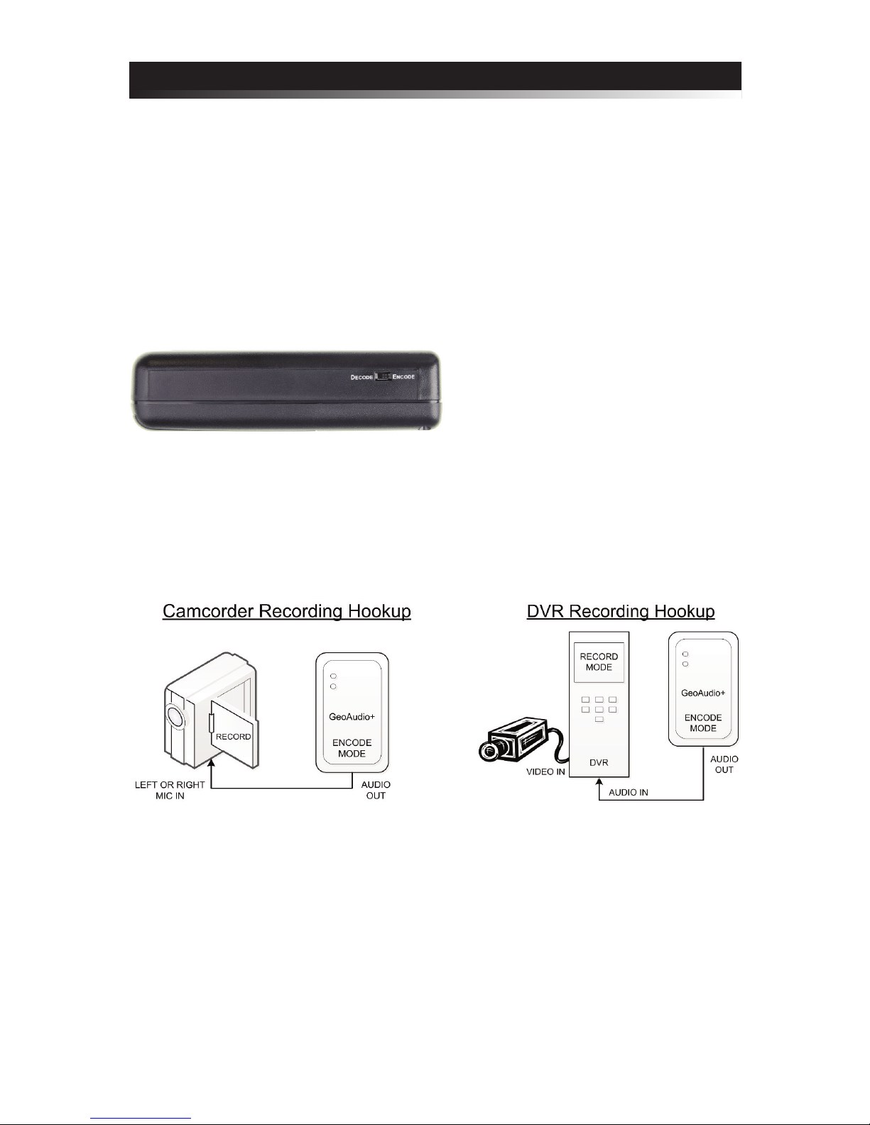
The ENCODE or DECODE operation mode is selected via the slide switch on the side
of the case. (See Figure 2.0)
Figure 2.0 – Mode selection switch
Encode Mode (Recording) Cable Hookup:
Use the supplied 6’ 3.5 mm audio cable to connect GeoAudio+ to the camcorder mic
input or DVR (digital video recorder) audio input. (See Figure 3.0 and 4.0)
Figure 3.0 – Camcorder Recording Hookup
Figure 4.0 – DVR Recording Hookup
Encode Mode (Recording) Operation:
After powering-up GeoAudio+ the yellow GPS Fix LED on the top of the case will
turn on once there is a good GPS fix (a minimum of 4 GPS satellites are being tracked.)
If the yellow GPS Fix LED does not turn on after approximately 2 minutes then verify
that the GeoAudio+ top of the case is facing up to a clear view to the open sky or the
optional external GPS antenna has a clear view to the open sky.
An audio adaptor connector may be required.

Decode Mode (Playback) Operation:
The yellow GPS Fix LED on the top of the case will blink during decode mode. For
PC operations please see the following sections for USB device driver installation and
mapping software configuration. Once the USB device driver has been installed then
PC mapping applications such as Google Earth can be used to view when and where
the events in the video being played back occurred.
The proper playback audio level must be set for reliable GPS decoding. Start with a
low output level then increase until reliable decoding occurs. DO NOT TURN THE
VOLUME TO MAX!
5
Figure 5.0 – PC Playback Hookup Figure 6.0 – Camcorder Playback Hookup
Figure 7.0 – DVR Playback Hookup
Decode Mode (Playback) Cable Hookup:
There are several playback hook-up options:
• Option #1 (see Figure 5.0) - use the supplied 6’ 3.5 mm audio cable and 6’ USB
A-Male to Mini-B cable to connect GeoAudio+ to the user’s PC.
• Option #2 (see Figure 6.0) - use the supplied 6’ 3.5 mm audio cable and 6’ USB
A-Male to Mini-B cable to connect the camcorder, GeoAudio+, and the user’s PC.
• Option #3 (see Figure 7.0) - use the supplied 6’ 3.5 mm audio cable and 6’ USB
A-Male to Mini-B cable to connect the DVR, GeoAudio+, and the user’s PC.
6
G
eoAudio+ Windows USB Device Driver
and Diagnostic Utility Installation
A USB software device driver must first be installed on a Microsoft Windows® PC
before GeoAudio+ can interface with PC applications. GeoAudio+ includes a disc with
the Microsoft Windows® USB device driver and GeoAudio+ Diagnostic Utility. Please
contact us for information regarding Linux and MAC OS X driver installation.
USB Device Driver:
To install the GeoAudio+ USB driver insert the supplied disc and run CDMxxxxx_Setup.exe.
If there are no error messages then the device driver was installed correctly.
The first time GeoAudio+ is connected to the PC and powered on Windows should
display two messages “Installing device driver software” followed by “Your device is
ready to use.”
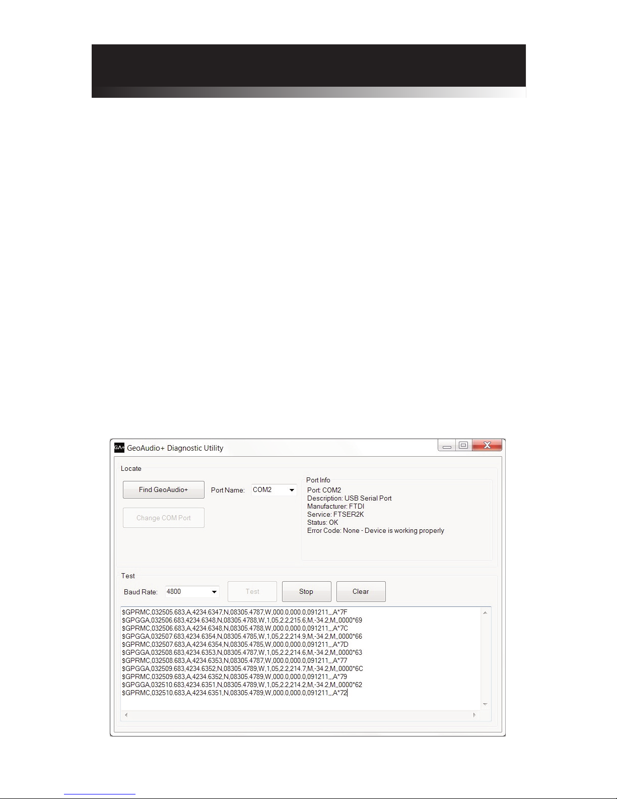
GeoAudio+ Diagnostic Utility Installation:
The GeoAudio+ Diagnostic Utility (see Figure 8.0) is a tool for verifying that the
GeoAudio+ is connected to the PC properly and decoded GPS information is being
received. GeoAudio+ Diagnostic Utility is not required to use GeoAudio+ but helpful
for troubleshooting.
To install the GeoAudio+ Diagnostic Utility insert the supplied disc, run setup.exe,
and follow the installation instructions.
Figure 8.0 – GeoAudio+ Diagnostic Utility
7
M
apping Application - Google Earth
GeoAudio+ can interface with most GIS (geographic information system) mapping
applications such as Google Earth. Google Earth requires a 4,800 baud rate so confirm
GeoAudio+ is configured for 4,800 baud (see Dip Switch Configuration above).
The supplied GeoAudio+ virtual COM port software driver causes the GeoAudio+
USB device to appear as a PC serial COM port. Mapping software such as Google
Earth can access the GeoAudio+ USB device in the same way as it would access a
standard PC serial COM port attached to an external GPS receiver.
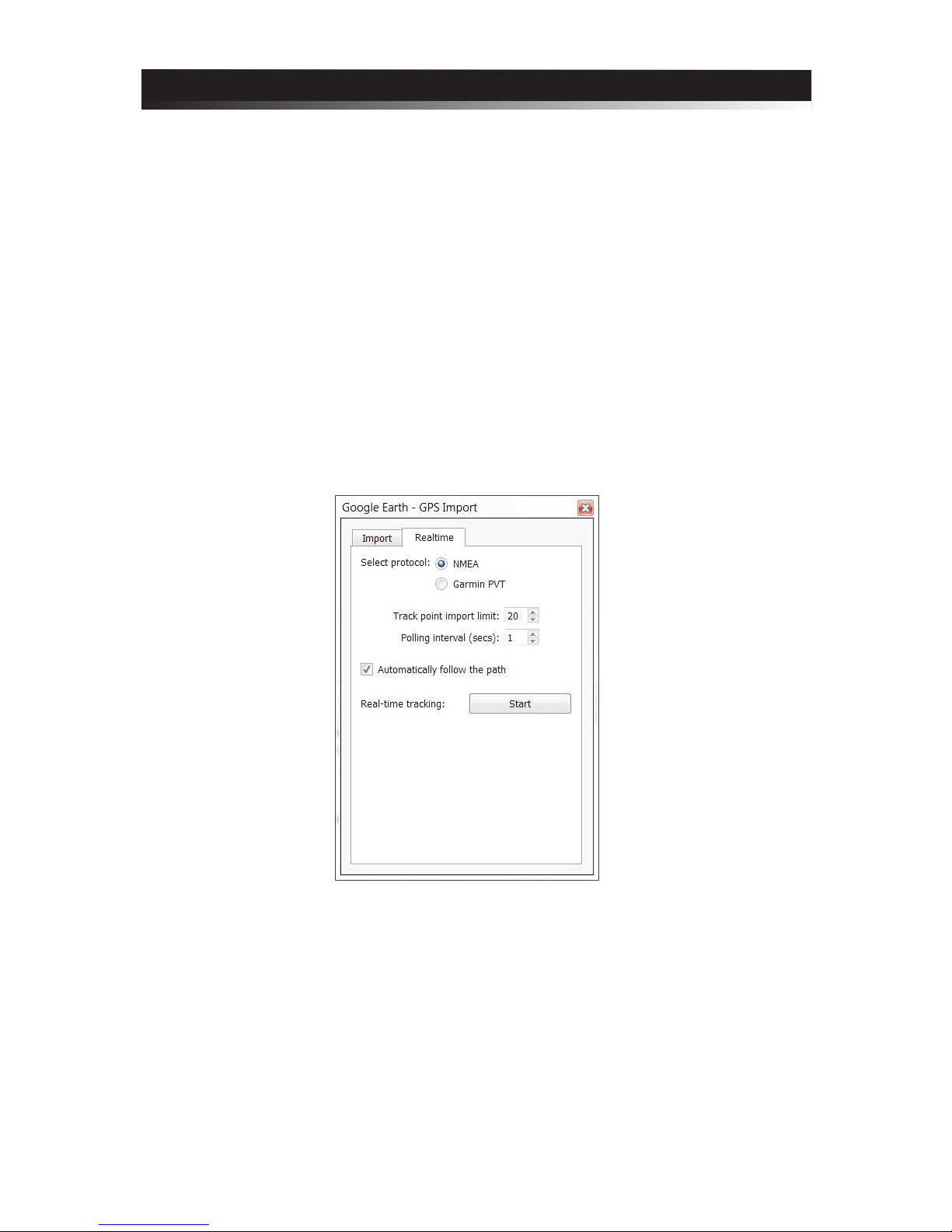
To access Google Earth GPS real-time mapping functionality go to the Google Earth’s
menu bar option “Tool” then select “GPS.” From the “GPS Import” window
(see Figure 9.0) select the “Realtime” tab. The “protocol” option must be set to NMEA.
Once the “Start” button is clicked then Google Earth will search for valid serial COM
Ports. Once the GeoAudio+ serial COM Port is found (GeoAudio+ must be decoding
data at that time) then Google Earth will begin updating the map.
Figure 9.0 – Google Earth - GPS Import Window

Intuitive Circuits, LLC
3928 Wardlow Ct.
Troy, MI 48083
Voice: (248) 588-4400
Fax: (248) 588-4455
http://www.icircuits.com
Solution
• Verify POWER switch in correct position
• Verify good AA batteries installed properly
• Wait 2 minutes for GPS satellite lock
• Verify that the GeoAudio+ top of the case is facing
up to a clear view to the open sky (for internal GPS
antenna version)
• Verify cables are connected properly and GeoAudio+
in Decode mode (blinking yellow LED)
• Run the GeoAudio+ Diagnostic Utility
• Verify GeoAudio+ and DVR devices are configured
properly (see configuration section above)
• The audio output consists of a “squawking” sound
T
rouble Shooting Tips
Problem
Green POWER LED off
(won’t power up)
Yellow GPS Fix LED off
while in Encode mode
Mapping software not
updating GPS real-time
position
W
arranty & Service
If the product fails to perform as described in our product description or specification,
within 1 year from the date of shipment to the buyer, we will repair or replace the
product and/or accessories originally supplied. Failure due to improper installation,
misuse, abuse or accident is not covered by this warranty. Incidental and consequential
damages are not covered by this warranty. The buyer must first obtain a Return
Material Authorization number by calling (248) 588-4400, or send email to
support@icircuits.com. Ship the defective product (with RMA number) to
Intuitive Circuits, 3928 Wardlow Ct., Troy, MI 48083, freight prepaid.
 Loading...