


NEWTON
USER MANUAL 0.9.1
INTUITIVE AERIAL AB
2016-11-10


NEWTON i
USER MANUAL
CONTENTS
1 Introduction 1
1.1 Overview . . . . . . . . . . . . . . . . . . . . . . . . . . . . . . . . . . . . . . . . . 1
1.2 Warnings and reservations . . . . . . . . . . . . . . . . . . . . . . . . . . . . . . . . 1
1.3 Physical layout . . . . . . . . . . . . . . . . . . . . . . . . . . . . . . . . . . . . . . 3
2 Operation 6
2.1 Unboxing and assembly . . . . . . . . . . . . . . . . . . . . . . . . . . . . . . . . . 6
2.2 Attaching camera and balancing . . . . . . . . . . . . . . . . . . . . . . . . . . . . . 6
2.3 Starting and connecting . . . . . . . . . . . . . . . . . . . . . . . . . . . . . . . . . 9
2.4 Tuning . . . . . . . . . . . . . . . . . . . . . . . . . . . . . . . . . . . . . . . . . . 9
2.5 User Interface . . . . . . . . . . . . . . . . . . . . . . . . . . . . . . . . . . . . . . . 10
2.6 Settings . . . . . . . . . . . . . . . . . . . . . . . . . . . . . . . . . . . . . . . . . . 11
3 Maintenance 13
3.1 Cleaning . . . . . . . . . . . . . . . . . . . . . . . . . . . . . . . . . . . . . . . . . . 13
3.2 Firmware update . . . . . . . . . . . . . . . . . . . . . . . . . . . . . . . . . . . . . 13
3.3 Calibration . . . . . . . . . . . . . . . . . . . . . . . . . . . . . . . . . . . . . . . . 13
4 Troubleshooting 15
A Connectors and pin-outs 16
A.1 Pan-box connectors . . . . . . . . . . . . . . . . . . . . . . . . . . . . . . . . . . . 16
A.2 Cradle connectors . . . . . . . . . . . . . . . . . . . . . . . . . . . . . . . . . . . . 17
B Technical specifications 18
C Revisions 20
DO NOT DISTRIBUTE
Copyright © 2016 Intuitive Aerial AB

NEWTON 1
USER MANUAL
1 Introduction
1.1 OVERVIEW
The Newton remote head is a fully electronically stabilized, three axis with free pan made for broadcast
and film production from cranes, wires, rails and vehicles.
The Newton is designed to be paired with the Dominion remote controller. Connection between
them can be either wireless or wired and the Dominion provides full control of all the functions of the
Newton.
1.2 WARNINGS AND RESERVATIONS
WARNING
Before connecting or turning on the Newton remote head read this manual
carefully.
WARNING
Do not power or charge the Newton controller with anything but external
power supplies delivered and approved by Intuitive Aerial for use with
Newton. Doing so can permanently damage or destroy your Newton.
Newton accepts external power between 12 volt and 26 volt. Powering it
with more than that can permanently damage it.
WARNING
Make sure that the camera and any other equipment is properly secured
before turning on the Newton.
WARNING
The Newton is rain protected but it is not water proof, so do not expose it
to direct spraying water or submersion into water.
WARNING
To get the best possible range, always extend the antennas vertically when
using and make sure they have a free line of sight to the controller.
DO NOT DISTRIBUTE
Copyright © 2016 Intuitive Aerial AB

NEWTON 2
USER MANUAL
WARNING
Performing any disassembly, modification or service not explicitly outlined
in this manual will void any warranties on the system.
DO NOT DISTRIBUTE
Copyright © 2016 Intuitive Aerial AB
NEWTON 3
USER MANUAL
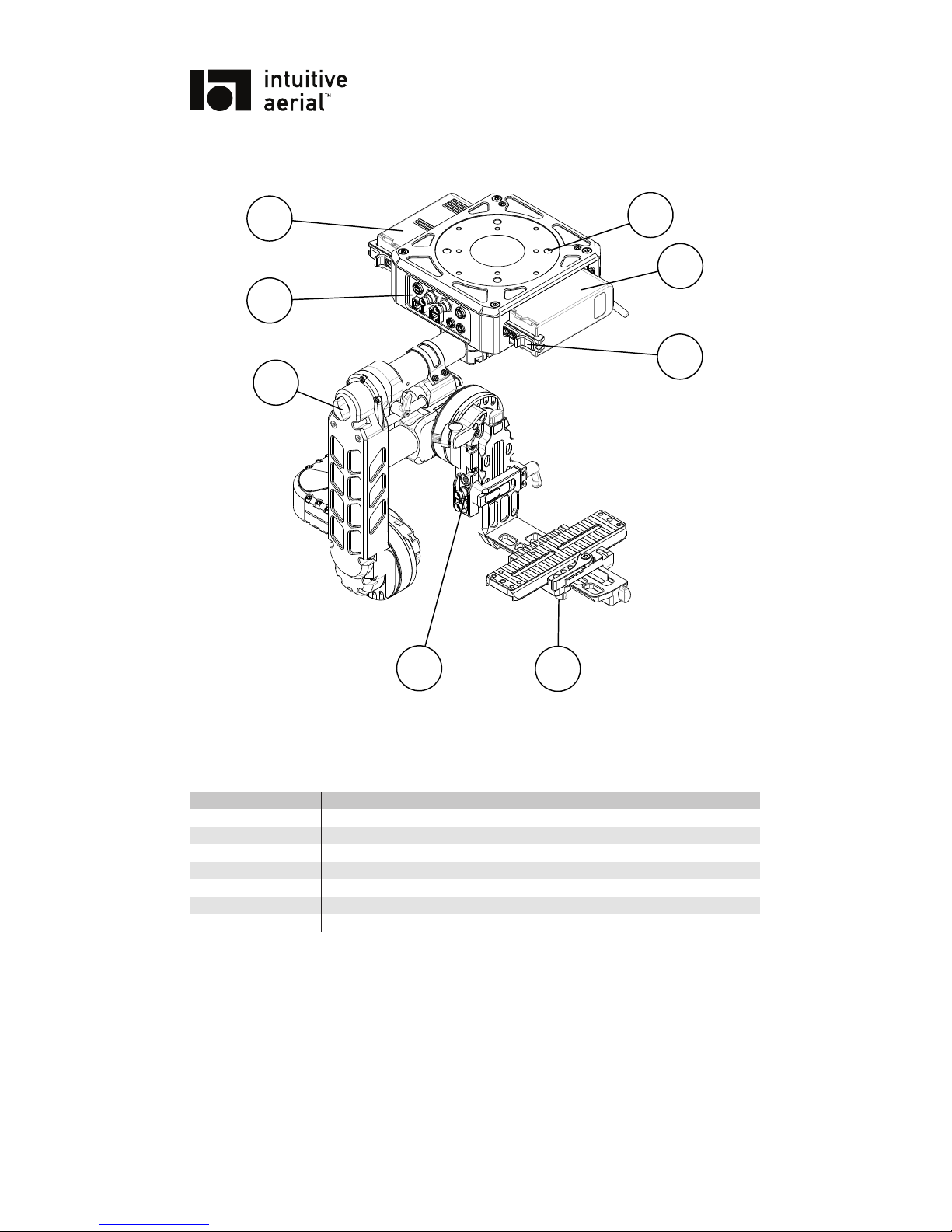
1.3 PHYSICAL LAYOUT
6
5
4
3
2
1
8
7
Figure 1.1: Newton overview 1
Table 1.1: Overview Descriptions
Item Description
1,3 Battery
2 Attachment points
4 Battery clamp
5 Side-to-side lock clamp
6 Cradle connectors
7 Pan balance adjustment screw
8 Pan-box connectors
DO NOT DISTRIBUTE
Copyright © 2016 Intuitive Aerial AB
NEWTON 4
USER MANUAL
9
10
11
16
14
17
20
23
21
18
12
19
13
15
22
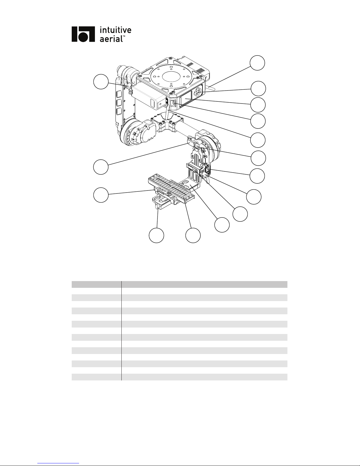
Figure 1.2: Newton overview 2
Table 1.2: Overview Descriptions
Item Description
9,13 Antennas
10 UI buttons
11 Display
12 Power switch
14 Vertical adjustment screw
15 Cradle connectors
16 Vertical lock clamp
17 Cradle release clamp
18 Cradle
19 Camera dovetail
20 Horizontal adjustment screw
21 Front-back lock clamp
22 Top-mount attachment
23 Pan balance lock clamp
DO NOT DISTRIBUTE
Copyright © 2016 Intuitive Aerial AB

NEWTON 5
USER MANUAL
Figure 1.3: Newton pan-box connectors
Figure 1.4: Newton cradle connectors
DO NOT DISTRIBUTE
Copyright © 2016 Intuitive Aerial AB

NEWTON 6
USER MANUAL
2 Operation
2.1 UNBOXING AND ASSEMBLY
When delivered the Newton is packed into a hard case with form fitting foam. The top layer has spaces
for auxiliaries and cables while the Newton itself is placed in the second layer. It is recommended to
use the hard case for storage and transport to reduce the risk of any damage to the head.
Unbox the Newton by pulling it straight up out of the foam and place it on a stable base or directly
attach it to the place it will be used, such as crane arm or rail system. Make sure it is securely attached.
The remote head has one detachable part, the camera cradle (point 18) and dovetail (point 19), that is
removed when packing it into the hard case. Reattach it by engaging the cradle release clamp and then
sliding it straight down all the way until it is attached.
2.2 ATTACHING CAMERA AND BALANCING
2.2.1 ATTACHING CAMERA
1
2
3
4
6
7
5
Figure 2.1: Attaching camera
To attach the camera to the camera slider dovetail, do
1. Remove the dovetail from the cradle:
1.1 Release the front-back lock clamp (point 21)
1.2 Pull down the adjustment pin
2. Attach the camera to the dovetail with two or more screws
3. Reattach the dovetail to the cradle:
3.1 Pull down the adjustment pin
3.2 Slide the dovetail into the base, position it at approximate front-back balance.
3.3 Lock the front-back lock clamp (point 21)
DO NOT DISTRIBUTE
Copyright © 2016 Intuitive Aerial AB

NEWTON 7
USER MANUAL
If using a long lens it is recommended to mount a forward lens support on rods; 15mm rods for lens
support or focus/iris/zoom motors can be attached to the dovetail base. After attaching the camera,
attach any auxilary devices such as focus/iris/zoom systems, interface dongles and cabling. Make sure
everything is tightly attached and cannot move or vibrate and strap together all cables tightly with cable
straps or Velcro.
! NOTICE !
It is highly recommended to always use a top mount on the camera, or a
full cage solution that gives the same function. The extra rigidity such a
solution gives is very important for optimal stabilization.
2.2.2 EXTERNAL CONNECTORS
Newton has a number of connectors, both on the pan box base and on the camera cradle. A few
of these provide direct pass-through functionality such as the two HD-SDI/BNC connectors and the
pass-through ethernet1, while others are part of the control interface.
The control Ethernet connection on the pan box is used for connecting by Ethernet cable to the
Dominion controller.
The IACAN connectors, both the one on the pan box and on the camera cradle, are both used for
firmware upgrades and to connect camera/lens interface dongles.
Finally the power connections; the power in on the pan box is used to power the Newton. The
power out on the pan box is an unregulated output from either the batteries or the external power in,
whichever provides a higher voltage. The cradle power output is a regulated 15V output. To protect
the internal wiring of the Newton is has a limited output power, it is limited to 67 watt when running
on 12 volts, 84 watt when running on 15 volt and 105 watt when running on 20 volts or higher.
2.2.3 BALANCING
In order to use the Newton the head must be properly balanced. First and foremost the balance must
be done so that the motor can stabilize the payload, too much offset in one axis can make it impossible
to steer and stabilize that particular axis. The more meticulously balanced to head is the better the
stabilization will work especially in highly dynamic environments.
Before you start the process of balancing the Newton you need to make sure that everything that’s
needed is mounted to the head as the addition accessories will affect the balance. Remember to loosen
any top mounts and similar before trying to balance the camera and to re-tighten them when done.
1
Can either be used for Ethernet or another signaling protocol with the right cable adapters
DO NOT DISTRIBUTE
Copyright © 2016 Intuitive Aerial AB

NEWTON 8
USER MANUAL
x
x
x
x
x
x
x
x
x
Figure 2.2: Balancing
Front-back balance
The first step is to adjust the front-back balance. Start by releasing the front-back lock clamp (point
21) and then push the adjustment pin button and move the camera package to the fixed position where
the balance is the best. Release the pin and then use the adjustment knob (point 20) on the side of the
cradle to do the last fine adjustments.
Some camera/lens setups that are long and front-heavy may need counterweights or a special camera cage in order to be able to balance it properly.
Vertical Balance
Rotate the tilt axis 90° forward or backwards. Release the lock (point 16) and adjust the vertical slider
(point 14) until good balance is achieved. To test the front-back and vertical balance, rotate the camera around the tilt axis to different angles and check if it stays in same angle. If not, make further
adjustments of balance.
Roll Balance
The roll balance is adjusted with the same knob (point 20) that was used for doing fine adjustments in
tilt. Make sure the front-back lock (point 21) is closed and loosen up the horizontal slider side-to-side
lock (point 5).
DO NOT DISTRIBUTE
Copyright © 2016 Intuitive Aerial AB

NEWTON 9
USER MANUAL
Pan Balance
The pan balance can be adjusted by turning the knob (point 7) on the back of the spine. Start by
loosening the pan lock (point 23), if the head is standing the spine will start to move sideways so its
important to prevent the head from tipping to the side. It’s recommended to have one person holding
the head while another do the pan adjustment to mitigate this risk.
By tipping the base of the head slightly to its side it should not move if the head is balanced. If the
back of the head moves to the opposite side it is back heavy and the knob should be turned clockwise.
If the moves to the other side the head is front heavy and the knob should be turned counter clockwise.
2.3 STARTING AND CONNECTING
Before turning on the Newton make sure everything is securely attached and that the system is balanced
as per the previous section. Also make sure batteries are properly attached or external power-in is
connected.
Turn on the Newton using the power switch (point 12). When starting up the system will perform
a calibration of the gyros to get the best possible performance. During this time the head should not
be moved. During the calibration the display will show mode “IMU CALIB”. If the IMU calibration
should fail, for example due to movement, the system will beep a number of times and show “IMU
BIAS CALIB FAILED” at the bottom of the display. The head is still usable but can have excessive
drift in all axes. To correct it, turn off the head and turn it on again to force another calibration.
The Newton is made to be controlled from the Dominion remote controller. For detailed information on how to establish connection between them, either wireless or wired, please see “Dominion
User Guide”.
2.4 TUNING
When setting up the Newton, after attaching the camera and carefully balance it, the remote head needs
to be tuned for the specific setup to get good stabilization and avoid vibrations. The tuning depends on
on the mass distribution of the whole camera and lens package (including any other devices attached to
it) so while general guidelines and rough values can be provided for a specific setup, it is still required
that a full tuning is done after assembly.
Tuning is done through the user interface on the Dominion controller, in the settings menu, Re-
mote tuning tab. For each axis there are three principal tuning parameters and one auxiliary parameter.
The parameters are:
P Controls how strongly a disturbance or steering input is compensated. The main tuning parameter.
I Compensates for residual errors on longer movements.
D Dampens reaction to quick external disturbances.
Pos Gain Controls how quickly the head returns to correct position after a larger deviation.
The recommended procedure for tuning the Newton is as follows:
1. Make sure the remote head and camera is balanced and that nothing is loose or rattles
2. Set the P, I, and D for all axes to a low value. A good starting point is (4, 0.05, 0) for tilt, (3.5,
0.05, 0) for roll and (10, 0.05, 0) for pan
3. Doing one axis at a time, in the order tilt, roll, pan, tune:
3.1 Increase P until a high frequency oscillation begins, then back down to 80% of the value.
Use the controller and move the axis from endpoint to endpoint, if oscillations begin at
any angle reduce the P value further
DO NOT DISTRIBUTE
Copyright © 2016 Intuitive Aerial AB

NEWTON 10
USER MANUAL
3.2 Increase I until a low frequency oscillation begins, then back down to 80% of the value.
Again check if there is any angle that is more prone to oscillation and if so reduce the I
further
3.3 Check that the head responds well to external disturbances by pressing lightly on the axis.
If the remote head is prone to oscillation when returning to the starting position, increasing
D to about 5-10 should dampen it
4. After all axes are tuned, return and check so that there is no angle more prone to oscillation. If
so, repeat the entire process for all three axes.
2.5 USER INTERFACE
2.5.1 MAIN PAGE
The main page, shown after startup, provides feedback on all major functions.
Supply voltage Battery voltages
Mode indication
Communication interface
Controller
FIZC interfaces
Figure 2.3: Main page
The top row shows:
1. Supply voltage (either battery or external)
2. Battery voltage for battery 1 and 2
3. Currently active communication link
Under this is a mode indicator. On startup this will show which calibration step is currently exe-
cuting, and after that what mode has been activated from the remote control. Together with the mode
DO NOT DISTRIBUTE
Copyright © 2016 Intuitive Aerial AB

NEWTON 11
USER MANUAL
indication is also an indication of any errors detected. If any error is shown, look at the troubleshooting
guide in chapter 4.
The bottom row of the screen shows currently connected controller (such as the Dominion) and
which camera/lens (FIZC) interface dongles are currently connected and identified.
2.6 SETTINGS
In addition to the settings listed in the section for tuning (section 2.4), the Newton has a number
of other settings. These can all be accessed from the Remote tune tab in the settings menu in the
Dominion.
Table 2.1: Settings - Tuning
Setting Range Description
<Axis> P 0 – 25 See section 2.4
<Axis> I 0 – 5
<Axis> D 0 – 20
<Axis> POS GAIN 0 – 50
CONTROL FILTER 0.5 – 10 Controls smoothing of the control input.
STOW ENCODER ENABLED
DISABLED
Controls the stow mode.
TILT MIN ANGLE −145° – 0° Adjust the min/max angle limit of the
axis
TILT MAX ANGLE 0° – 145°
ROLL MIN ANGLE −60° – 0°
ROLL MAX ANGLE 0° – 60°
TILT ANGLE CORR −5° – 5° Correct for IMU mounting deviation
ROLL ANGLE CORR −5° – 5°
PAN ANGLE CORR −5° – 5°
PAN FOLLOW ENABLED
DISABLED
PAN FOLLOW STRENGTH 0 – 90 Controls how tightly the camera is fol-
lowing the base of the Newton
2.6.1 STOW ENCODER
There are two different ways that the Stow mode on the Newton can work. When STOW ENCODER
setting is set to “DISABLED” the stabilization will be disabled and all motors turned off. When
“ENABLED” the stabilization will remain in a basic mode and use encoders to hold the camera in a
neutral position.
2.6.2 MAX/MIN ANGLES
These settings allow updating of the software limits for control.
The angles given for min/max angle is IMU/world angles, not angles of the joints of the head.
2.6.3 ANGLE CORRECTION
In some cases there might be a small deviation between what the camera sees as zero-angle and what
the electronic control system considers zero-angle. In that case a small correction can be applied by
adjusting the ANGLE CORR settings.
DO NOT DISTRIBUTE
Copyright © 2016 Intuitive Aerial AB

NEWTON 12
USER MANUAL
2.6.4 PAN FOLLOW MODE
When follow mode is active the camera follows the base of the Newton. This can be useful for instance
when Newton is mounted on a car, the camera will follow the rotation of the car. Follow mode can
also be used to remove pan bias drift when the base of the Newton is not rotating, for instance when
mounted on a straight rail system. The PAN FOLLOW STRENGTH option controls how tightly
the camera follows the base.
DO NOT DISTRIBUTE
Copyright © 2016 Intuitive Aerial AB

NEWTON 13
USER MANUAL
3 Maintenance
The Newton is a highly technical and very precise equipment with high requirements on exactness and
internal tolerances. In addition it contains weather sealing. For this reason it is not recommended to
ever disassemble the Newton or try to perform maintenance on any internal parts.
3.1 CLEANING
Clean the Newton externally using a soft, and if needed slight damp, cloth. If it is very dirty, use a mild
detergent such as washing up soap.
WARNING
Do not use any cleaning agents containing alcohols, acids or other
corrosive chemicals. Using such cleaning agents might damage the coating
and/or the display surface.
3.2 FIRMWARE UPDATE
Firmware updates are distributed by Intuitive Aerial in a single ZIP archive that contains software for
Newton, Dominion and the required updater application for Windows and OSX. Before updating
please read the attached release notes for any specific information pertaining to that release. When
upgrading the Newton, make sure to also update any FIZC dongles and the Dominion to a matching
version.
To upgrade the Newton remote head, follow the procedure below:
1. Connect the USB/CAN dongle to the CAN port on the pan-box of the Newton
2. Start the upgrade application, named “firmware_gui.exe” on Windows or “firmware_gui.app”
on OSX.
3. Follow the instructions in the wizard. When asked for firmware file, select “newton_<ver-
sion>.zfw” in the firmware folder
4. When finished, restart the Newton
3.3 CALIBRATION
When delivered the Newton is factory calibrated. Normally this calibration will not need to be redone,
however sometimes long usage, big cyclic changes in temperature or upgrades to new firmware will
make a re-calibration necessary. The calibration options can be reached from the Remote service
settings tab in the Dominion, which is part of the service mode
1
If unsure, do not perform any calibrations unless directed to by Intuitive Aerial support staff.
1
See the Dominion manual for detailed information
DO NOT DISTRIBUTE
Copyright © 2016 Intuitive Aerial AB

NEWTON 14
USER MANUAL
3.3.1 ZERO ANGLE CALIBRATION
Zero angle calibration serves to record the neutral, zero angle, positions of the joints. This is needed
both for the “STOW” mode but also for correct operation of the stabilization. To set the zero angle
calibration:
1. Hang the Newton from a stable mounting point
2. Make sure both Newton and Dominion are turned on and connected
3. Activate “START ZERO ANGLE” in the Dominion
4. Position the Newton so that all angles are at their neutral zero position
5. Press “FINISH” on the Dominion
3.3.2 MOTOR ALIGNMENT
1. Place the Newton with the pan box down on a stable work surface or table. Do not attach any
camera.
2. Make sure both Newton and Dominion are turned on and connected
3. Activate “START ALIGN” in the Dominion
3.3.3 REALIGN IMU - EXPERIMENTAL FEATURE
If the Horizon of the Newton is off the IMU can be realigned. Note that the Newton should be kept
still when doing this.
3.3.4 ZERO ROLL - EXPERIMENTAL FEATURE
Zero roll allows for manual correction of the horizon.
1. Go to roll velocity mode
2. Adjust the roll angle with the joystick until the horizon is correct, then press ZERO ROLL
3. Now turn 90 degrees in pan. Repeat step 2. and the horizon is corrected
DO NOT DISTRIBUTE
Copyright © 2016 Intuitive Aerial AB

NEWTON 15
USER MANUAL
4 Troubleshooting
Problem Possible Cause(s) Solution(s)
Newton does not start up Batteries are empty Exchange to fully charged batteries
No external power connected
Connect external power supply to Newton
Dominion does not establish connection with
Newton
Antennas are not
mounted
Mount antennas
Dominion and Newton
are not paired
Perform pairing procedure, see Dominion manual
There is a constant drift
in pan, tilt or roll
Input calibration is not
properly done
Immediate solution: Use deadband setting to compensate. See Dominion user
manual or contact support for instruc-
tions on how to redo calibration
There is a very small drift
present in pan due to gyro
bias
Activate the trim functionality to elimi-
nate drift manually, see Dominion man-
ual
Camera/lens interface
dongle is not recognized
by Dominion
Dongle has incompatible
firmware
Update dongle firmware to same version
as Dominion
Communication link is
not established between
Newton and Dominion
See entry above
There is a small constant
offset on either roll or tilt
IMU or cradle not perfectly orthogonal
Adjust the roll or tilt angle correction.
See section 2.6.3.
Display shows “IMU
BIAS CALIB FAILED”
Newton was not still during startup. It might lead
to reduced performance
Restart Newton, make sure not to disturb
the camera until display shows “STOW”
DO NOT DISTRIBUTE
Copyright © 2016 Intuitive Aerial AB

NEWTON 16
USER MANUAL
A Connectors and pin-outs
The HD-SDI and the 8P8C/RJ45 pass-through connector provides a one-to-one connection between
the pan-box and cradle.
The IA-CAN connector is proprietary to Intuitive Aerial equipment.
A.1 PAN-BOX CONNECTORS
A.1.1 POWER IN
Mating connector: LEMO EGJ.1B.304
Acceptable voltage: 12V – 26V
1
23
4
Figure A.1: Power in
Table A.1: Power in, pins
Pin number Description
1,2 Positive (+)
3,4 Negative (-)
A.1.2 POWER OUT
Mating connector: LEMO EGG.1B.304
Output voltage: Unregulated input / battery voltage
Max current: 3.3A
1
2 3
4
Figure A.2: Power out
Table A.2: Power out, pins
Pin number Description
1,2 Negative (-)
3,4 Positive (+)
DO NOT DISTRIBUTE
Copyright © 2016 Intuitive Aerial AB

NEWTON 17
USER MANUAL
A.2 CRADLE CONNECTORS
A.2.1 POWER OUT
Mating connector: LEMO EGG.1B.304
Output voltage: Regulated 15V
Max current: up to 6.5A
1
2 3
4
Figure A.3: Power out
Table A.3: Power out, pins
Pin number Description
Pin number Description
1,2 Negative (-)
3,4 Positive (+)
DO NOT DISTRIBUTE
Copyright © 2016 Intuitive Aerial AB

NEWTON 18
USER MANUAL
B Technical specifications
Table B.1: Mechanical
Parameter
Min
Typ Max
Length
1
XX cm
Width
1
XX cm
Height
1
XX cm
Weight
1
XX kg
1
Without camera
Table B.2: Camera
Parameter
Min
Typ Max
Length
1
XX cm
Width XX cm
Height XX cm
Weight XX kg
1
Length behind center-of-gravity
Table B.3: Power supply
Parameter
Min
Typ Max
Power input
Input voltage
12 V
24 V 26 V
Input current 16 A
Pan-box power out
Output voltage
1
12 V
24 V 26 V
Output current 3.3 A
Cradle power out
Output voltage
14.5V
15 V 15.5 V
Output current
2
6.5 A
Output power
2
105 W
1
Unregulated input/battery voltage
2
Depends on input/battery voltage
DO NOT DISTRIBUTE
Copyright © 2016 Intuitive Aerial AB

NEWTON 19
USER MANUAL
Table B.4: Communication interface
Parameter
Min
Typ Max
n2420 Modem
Frequency
2400 MHz
2484 MHz
Power Output 100 mW 1W
Range 1 km
Ethernet
Speed 100 Mbit
Cable length 50 m
Table B.5: Shipping/hard-case
Parameter
Min
Typ Max
Length 62 cm
Width 55 cm
Height 29 cm
Weight
1
19 kg
1
Including two Watson batteries and charger
DO NOT DISTRIBUTE
Copyright © 2016 Intuitive Aerial AB

NEWTON 20
USER MANUAL
C Revisions
Rev Date Changes
1 2016-08-01 Initial version
DO NOT DISTRIBUTE
Copyright © 2016 Intuitive Aerial AB
 Loading...