

Page 1

Intuicom®
Wireless RTK Bridge - Cellular
User Guide
Intuicom, Inc.
1880 S Flatiron Court
Boulder, CO 80301
(303) 449-4330
www.intuicom.com
Page 2

Wireless RTK Bridge – Cellular User Guide
This manual is for use by purchasers and other authorized users of the Intuicom Products. No
part of this document may be reproduced or transmitted in any form or by any means, electronic
or mechanical, or for any purpose without the express written permission of Intuicom Inc.
© 2000 - 2009 Intuicom Incorporated. All rights reserved.
Intuicom reserves the right to make changes to this manual without notice. Unless otherwise
agreed to in writing, Intuicom assumes no responsibility or liability for the use of this manual or
for the infringement of any copyright or other proprietary right and Intuicom shall deem nothing
contained in this manual a warranty or guarantee.
Intuicom, CommPro, WiGate, Nav-Link, TargeTracker, Intuicom Navigator II, Navigator IIm
and Intuicom Communicator II, Communicator T, 1200 Data Link, DIO, and Wireless RTK
Bridge are trade names of Intuicom, Inc.
Other product names mentioned in this manual may be copyrights, trademarks, or registered
trademarks of their respective companies and are hereby acknowledged.
Revision 1.4 i © 2009 Intuicom Inc.
Page 3

Wireless RTK Bridge – Cellular User Guide
This product is licensed by The United States.
Diversion contrary to U.S. law is prohibited.
Shipment or re-export of this product outside of The
United States may require authorization by the U.S.
Bureau of Export Administration. Please contact
Intuicom, Inc. for assistance and further information.
Revision 1.4 ii © 2009 Intuicom Inc.
Page 4

Wireless RTK Bridge – Cellular User Guide
Table of Contents
Overview ................................................................................................................................ 1
1
1.1
Key Features ................................................................................................................... 1
1.2
Front Panel Connectors and Controls ............................................................................ 2
1.3
Example Applications ..................................................................................................... 3
2Initialization and Configuration .......................................................................................... 6
2.1
Accessing the Configuration Menu ................................................................................. 6
2.2
Embedded Cellular Modem Activation ........................................................................... 9
2.2.1Verizon Service (US Customers) .............................................................................. 11
2.2.2GSM/GPRS/EDGE Service ...................................................................................... 13
2.3
Configuration Process .................................................................................................. 16
2.3.1Administrative........................................................................................................... 22
3Operation ............................................................................................................................. 24
3.1
Basic Steps for Operation ............................................................................................. 24
3.2
Startup Sequence ........................................................................................................... 27
3.3
Front Panel LEDs ......................................................................................................... 28
3.4
Config Port Status Display/Messages ........................................................................... 30
3.5
Antenna Aiming / Cellular Signal Strength Mode ........................................................ 32
3.6
Changing Profiles ......................................................................................................... 33
3.7
Optimizing Wireless Performance ................................................................................ 34
3.8
Connecting to Third-Party Radio ................................................................................. 36
4Troubleshooting .................................................................................................................. 37
5Accessories ........................................................................................................................... 39
6Technical Support ............................................................................................................... 41
7FCC Notification ................................................................................................................. 42
8Warranty ............................................................................................................................. 43
Revision 1.4 iii © 2009 Intuicom Inc.
Page 5

Section 1: Overview
1 Overview
The Intuicom Wireless RTK Bridge - Cellular expands access to GNSS network RTK
corrections for rover users in the field. The RTK Bridge - Cellular combines an embedded GPS
and cellular (CDMA or GSM/GPRS/EDGE) Internet connectivity with an Intuicom Wireless
Data Radio with to support a wide range of deployment configurations.
1.1 Key Features
• Connect to the Internet using a choice of either an embedded CDMA or
GSM/GPRS/EDGE cellular modem
• Connect to NTRIP Casters and stream any data/messages/corrections, etc.
• Connect to Raw/Dedicated TCP Sockets (non NTRIP)
• Embedded GPS can provide unit’s position to the GNSS network server for
individualized corrections or virtual reference station creation. Optionally enter a
user supplied fixed location or passthrough GGA messages from an external source
• All correction messages received are available on a front panel serial port for
connection directly to a GNSS rover, or to a third party radio for rebroadcast.
• Unit can provide authentication messages for Leica Spider ($GPUID) GNSS server
• Compatible with Intuicom 1200 Data Link radios for easy Leica System 900 and
1200 integration, as well as Intuicom Communicator and Communicator II, radios in
both Point-to-Multipoint and TDMA modes
• Compatible with Intuicom wireless data repeaters to extend wireless coverage area
• Store up to four configuration sets called “PROFILES” that can be selected for use in
the field without a PC– a PROFILE contains configuration data such as GNSS server
IP, port, username, password, mountpoint, static location, front panel baud rate, etc.
Revision 1.4 1 © 2009 Intuicom, Inc.
Page 6
Section 1: Overview
1.2 Front Panel Connectors and Controls
987
GPS RADIO
MDM
54
6
CONFIG DATA
1 2
MODEM
RTK Bridge
4
3
2
1
SVR SIG GPS PWR
TXD
3
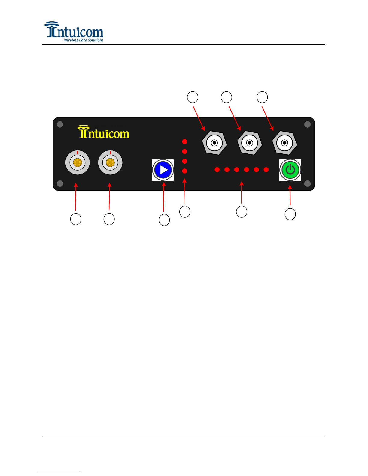
Figure 1-1: RTK Bridge - Cellular Front Panel
(1) Configuration / Power Port
(2) Data Copy Output / External GPS Input / Power Port
(3) Profile Select / Mode Select Button
(4) Current Profile / Modem Signal Strength (Antenna Aiming Mode)
(5) Status LEDs
(6) Power On/Off Button
(7) TNC antenna connector for internal CDMA/GSM/GPRS/EDGE modem
(8) TNC antenna connector for internal L1 GPS
(9) TNC antenna connector for internal Intuicom 900 MHz Wireless Data Radio or other
embedded data radio
Revision 1.4 2 © 2009 Intuicom, Inc.
Page 7
Section 1: Overview
1.3 Example Applications
Internet
RTCM 3 .x
RTCM 2 .x
CMR/CMR+
Leica
Spider/VRS/
NTRIP Ca s ter
CDMA/GSM
GSM/CDMA
Wireless Internet/Data
Intuicom RTK Bridge - Cellular
RTK Corrections
L1 GPS
Antenna
Intuicom 900 MHz
Spread Spectrum
Wireless Data
RTK Rover
Machine
Control
Construction
Agriculture
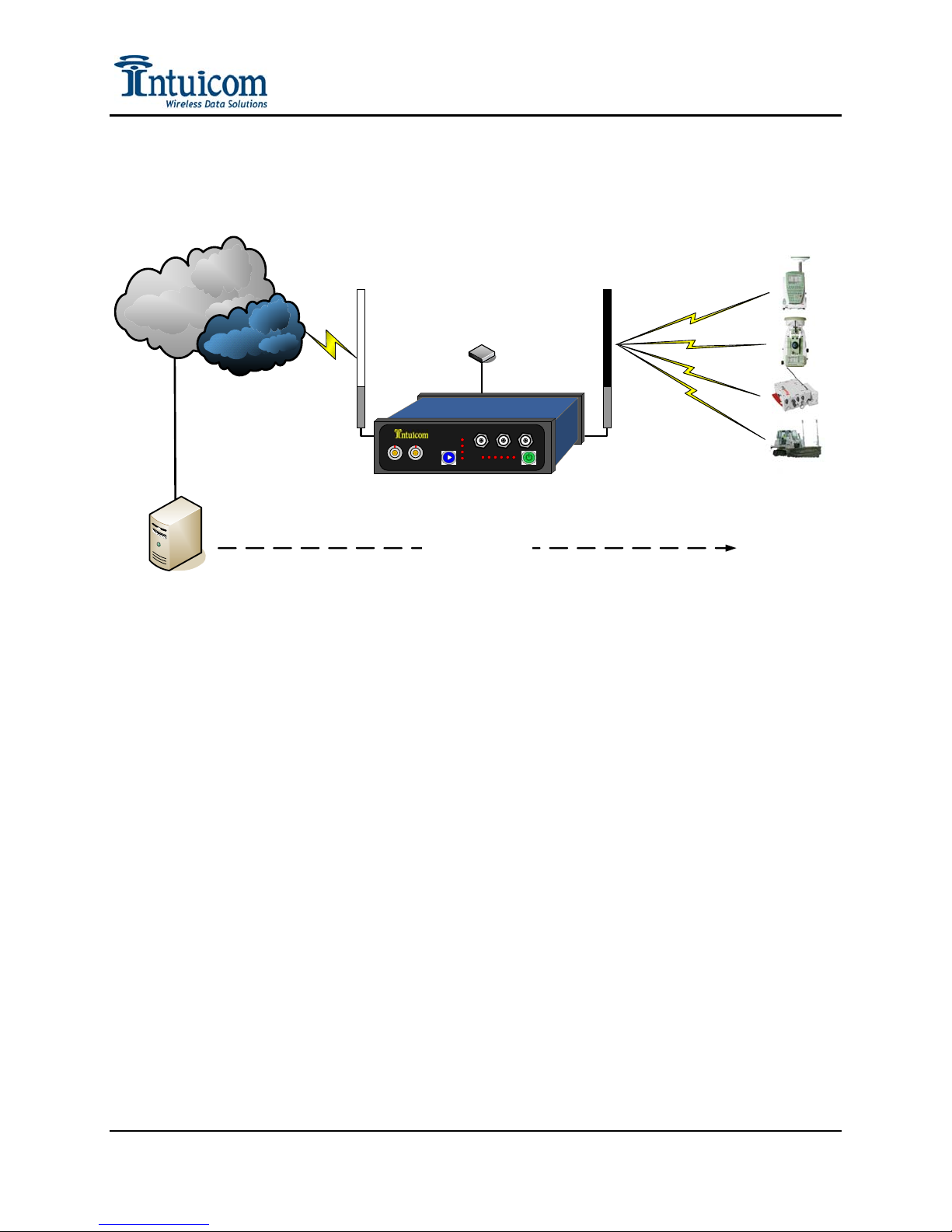
Figure 1-2: Intuicom Wireless RTK Bridge - Cellular Architecture Overview
Typical Application - The Intuicom Wireless RTK Bridge has a flexible configuration
and can be used to satisfy a range of connectivity needs. Typical installations have the
RTK Bridge configured to connect to an NTRIP Caster where it provides mountpoint and
authentication information. Once connected to a mountpoint, it will stream its GPS point
position (from its internal L1 GPS) allowing the Network Correction Server (such as
Leica Spider) to generate individualized corrections or create a virtual reference station.
The unit receives these corrections via IP and then broadcasts them to receiving RTK
rover units.
Revision 1.4 3 © 2009 Intuicom, Inc.
Page 8
RTCM 3. x
RTCM 2. x
CMR/CMR+
Leica
Spider/VRS/
NTRIP Caster
Internet
CDMA/GSM
Section 1: Overview
Intuicom 900 MHz
Spread Spectrum
Wireless Data
L1 GPS
Antenna
GSM/CDMA
Wi reless Intern et /Data
Intuico m RT K Bridge - Cellular
RTK Corrections
Optional Copy of RTK
corrections output on
Data Port
RS 232 Seri al
4800 -115200 Baud
Optional 3rd Party
400 MHz Base Rad i o
PacCrest/Trimble/
Topcon, etc.
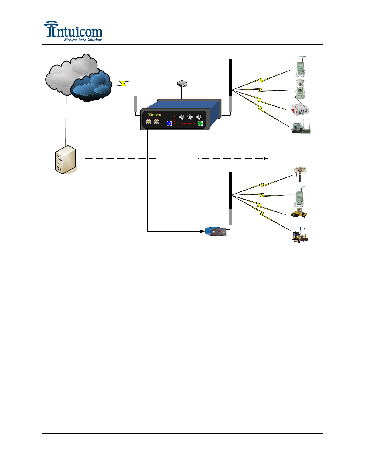
Figure 1-3: Intuicom RTK Bridge - Cellular used with third party base radio
Leveraging Existing Data Radios - The Intuicom Wireless RTK Bridge can be used to
supplement and existing wireless network, replacing the local base station GPS. Users
simply connect a third party base radio to the Data Out port on the front of the unit to
broadcast a copy of the correction stream. If no rover RTK users are utilizing Intuicom
Wireless Data Radios, the internal radio can be disabled to conserve power.
Revision 1.4 4 © 2009 Intuicom, Inc.
Page 9
CDMA/GSM
Internet
Spider/VRS/
NTRIP Ca s ter
Section 1: Overview
GSM/CDMA
Wireless Internet/Data
RTCM 3.x
RTCM 2.x
CMR/CMR+
Leica
Intuicom RTK
Bridge - Cellular
RTK Corrections
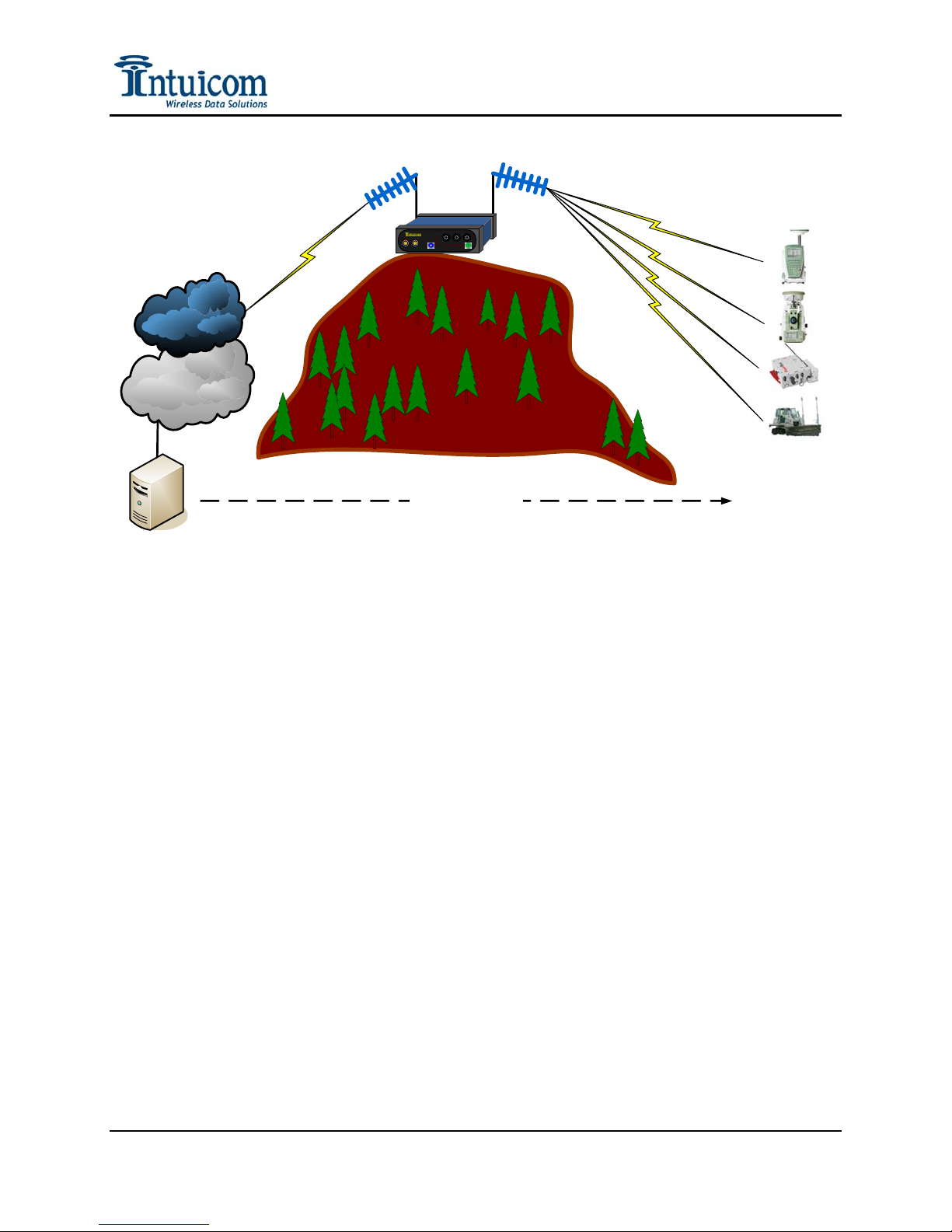
Figure 1-4: RTK Bridge Extending Carrier Data Network
Intuicom 900 MHz
Spread Spectrum
Wireless Data
Construction
RTK Rover
Machine
Control
Agriculture
Extending CDMA/GSM Data Service Reach – In this example, rovers are operating in an area
not directly covered by CDMA/GSM cellular data service. The rovers however are still within
the network of GNSS reference stations and thus can benefit from a network correction. Using a
high gain antenna on the CDMA/GSM cellular modem, a reliable connection can be established
allowing the RTK Bridge to connect to the Internet and the GNSS network server. Corrections
are streamed from the GNSS network server to the RTK Bridge where they are broadcast over an
Intuicom Wireless Data Network to all RTK rovers. In this case the rovers are utilizing Intuicom
1200 Data Link radios to receive the correction messages. Note that in this application, any
number of Rover users can receive the same correction messages broadcast from the RTK
Bridge. Furthermore, if the distance between the RTK Bridge and the rover users is great – the
RTK Bridge can be configured to report its position to the GNSS Network server as if it were in
the location of the rovers – further optimizing the network correction generated by the GNSS
network server.
Revision 1.4 5 © 2009 Intuicom, Inc.
Page 10
Section 2: Initialization and Configuration
2 Initialization and Configuration
Prior to the first use of the Intuicom RTK Bridge must be activated and configured. A onetime
process of activation is required to setup the integrated CDMA or GSM cellular modem for use
on the chosen carrier’s network. For the device to connect to the current GNSS Network server,
further configuration is required. The unit can store up to four configuration sets called Profiles.
In the field, the current Profile can be changed without the need of a PC. Profiles enable the user
to do things like change NTRIP mountpoints, change GNSS servers, change how locations sent
to the server, etc. At least one Profile must be configured.
2.1 Accessing the Configuration Menu
All configuration and initialization is performed by accessing the configuration menu on the
RTK Bridge with a PC using a terminal emulation program (such as HyperTerminal,
ProComm, TerraTerm, or Minicom), an available serial port, the power/data cable, the RTK
Bridge itself, and the power adapter for the RTK Bridge.
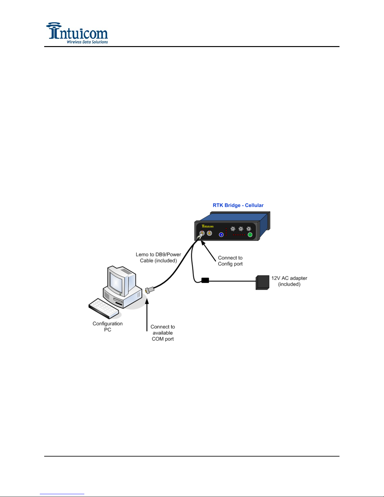
Figure 2-1: Cable Connections for Accessing Configuration Menu
To access the RTK Bridge configuration menu use the following steps:
1. Connect the Lemo end of the power/data cable to the CONFIG port of the RTK
Bridge, and the DB9 connector to an available DB9 COM port on the PC to be used
for configuration. If no COM port is available, a USB-COM port adapter may be
used. Attach the AC power adapter to the power connector on the power/data cable
and plug the AC adapter into an outlet.
Revision 1.4 6 © 2009 Intuicom, Inc.
Page 11
Section 2: Initialization and Configuration
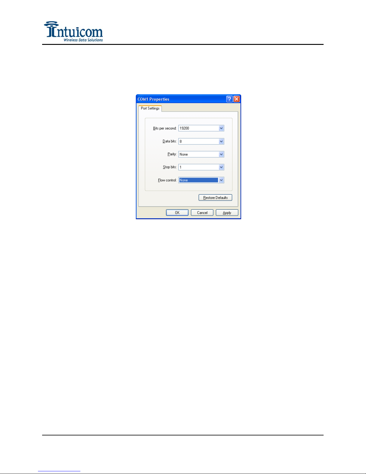
2. Start HyperTerminal, or another terminal program such as Procomm or TerraTerm,
and configure it to use the same COM port to which the cable was just attached, and
for 19200 baud, 8 data bits, 1 stop bit, no parity, and no flow control:
Figure 2-2: Hyperterminal Connection Properties Dialog
3. Power the RTK Bridge unit by pressing and holding the green power button until the
PWR LED turns red. Wait for approximately 30 seconds for the unit to boot, then
type “700” on the terminal screen to invoke the setup menu.
If the unit has not been activated (CDMA) or does not have a SIM inserted
(GSM/GPRS/EDGE), or is not within coverage, it may be necessary to type ‘q’ to
skip the modem’s network registration step.
Revision 1.4 7 © 2009 Intuicom, Inc.
Page 12
Section 2: Initialization and Configuration
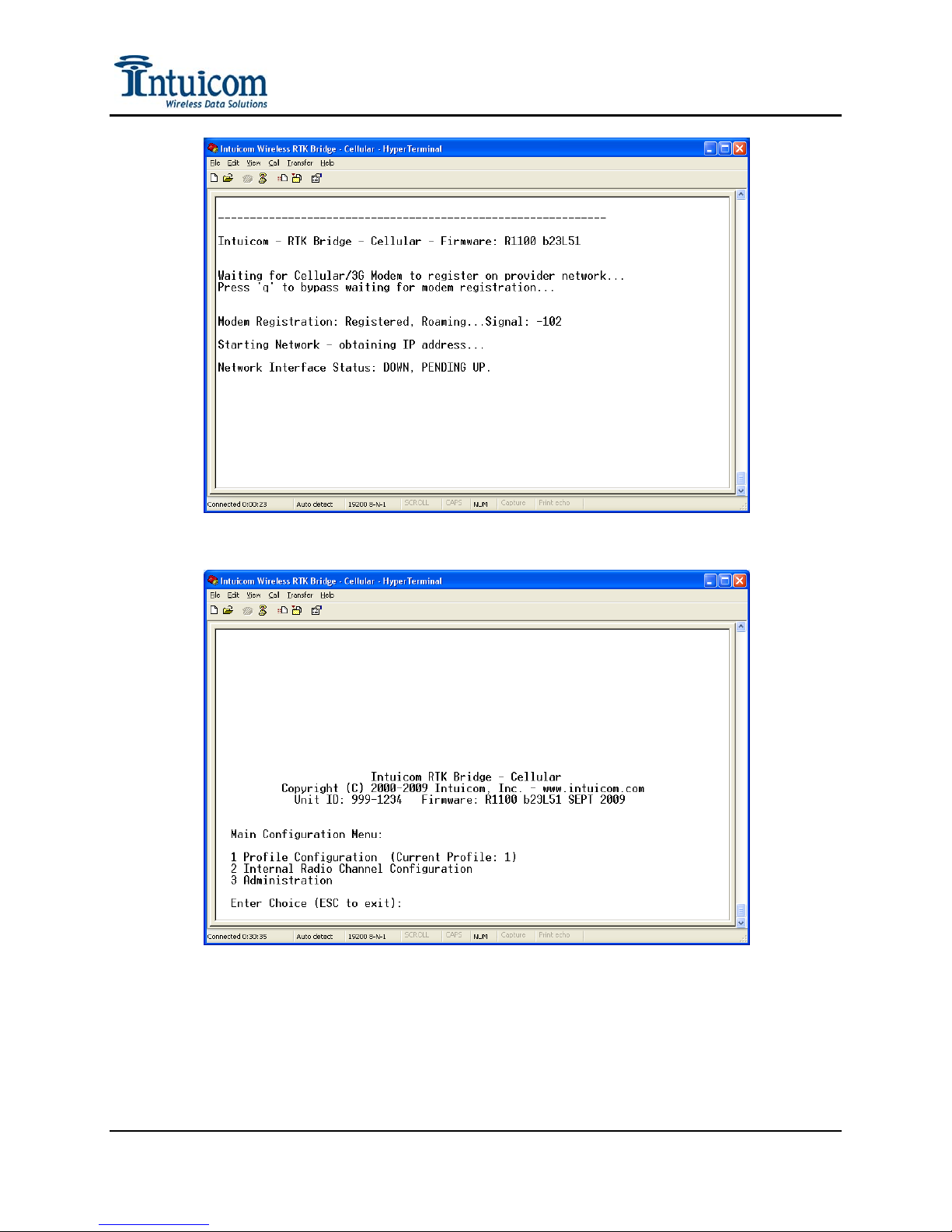
Figure 2-3: RTK Bridge Initial Startup Output
Figure 2-4: RTK Bridge Main Configuration Menu
4. You are now ready to interact with the configuration menus. Pressing the ESC key at
the top level menu will exit the menu and the unit will restart and begin running using
the currently selected PROFILE configuration parameters.
Revision 1.4 8 © 2009 Intuicom, Inc.
Page 13

Section 2: Initialization and Configuration
2.2 Embedded Cellular Modem Activation
The activation process involves two steps: contacting your carrier and establishing or adding
a new line to an account, and activating the device after the account/line has been
established. Currently the Intuicom RTK Bridge - Cellular can be ordered with an embedded
modem compatible with either Verizon (CMDA) or any GSM/GPRS/EDGE carrier such as
AT&T or T-Mobile. The activation process differs slightly depending on the carrier. In
either case you will typically need a few pieces of information available from the
configuration menu of the unit.
Access the modem configuration menu by selecting Administration->Embedded Cellular
Modem Configuration:
Revision 1.4 9 © 2009 Intuicom, Inc.
Figure 2-5: Administration Menu
Page 14

Section 2: Initialization and Configuration
Figure 2-6: Example Verizon Embedded Modem Configuration Screen
Figure 2-7: Example GSM/GPRS/EDGE Embedded Modem Configuration Screen
Revision 1.4 10 © 2009 Intuicom, Inc.
Page 15

Section 2: Initialization and Configuration
2.2.1 Verizon Service (US Customers)
Establishing Service
For a Verizon modem, service will need to be established by contacting Verizon Wireless
or your customer service representative:
www.verizonwireless.com/activateyourdevice
Business Sales: 800-899-4249
Government Sales: 800-293-3048
Customer Service: 800-922-0204
Provide the Verizon representative with the Intuicom RTK Bridge – Cellular identifier:
RTKBC-VZ and your unit’s Electronic Serial Number (ESN). The ESN (in HEX form)
can be found in the Embedded Cellular Modem Configuration menu as shown in or on
the label on the side of the device.
The most appropriate data plan for most users to request is “Mobile Broadband Access”.
This plan is a 5GB/month data only plan for a fixed monthly price. Note: used 24x7 with
a 1 Hz RTCM3 correction, an RTK Bridge should use ~ 2GB/month of data.
The representative will provide a 10-digit phone number (MDN) – record this number,
you will be prompted to enter it during the provisioning step. If not provided by the
Verizon representative, request the 10-digit “MIN” number. You will be prompted to
enter both numbers during the modem activation step next.
Activation
After service has been established with Verizon for your unit, a final activation step
completed on the RTK Bridge itself is required. The activation process for the Verizon
modem requires access to the carrier’s wireless network. If you are not located within
coverage, wait to complete the next steps until the unit is located Verizon wireless
network coverage. A Verizon mobile phone can be handy here to help verify coverage.
Attempting to activate the modem outside of Verizon coverage will not damage the unit
and activation can be attempted again later if it fails due to lack of wireless service.
Be sure the device has the modem antenna attached to the connector on the front panel.
From the Embedded Cellular Modem Configuration menu, select the Activation option.
You will be prompted to enter the 10-digit MDN number provided when the service was
established. Next you will be prompted for the MIN number. If the MIN is the same as
the MDN, enter the MDN a second time. Be sure to carefully and accurately enter this
number with no spaces.
Revision 1.4 11 © 2009 Intuicom, Inc.
Page 16
Section 2: Initialization and Configuration
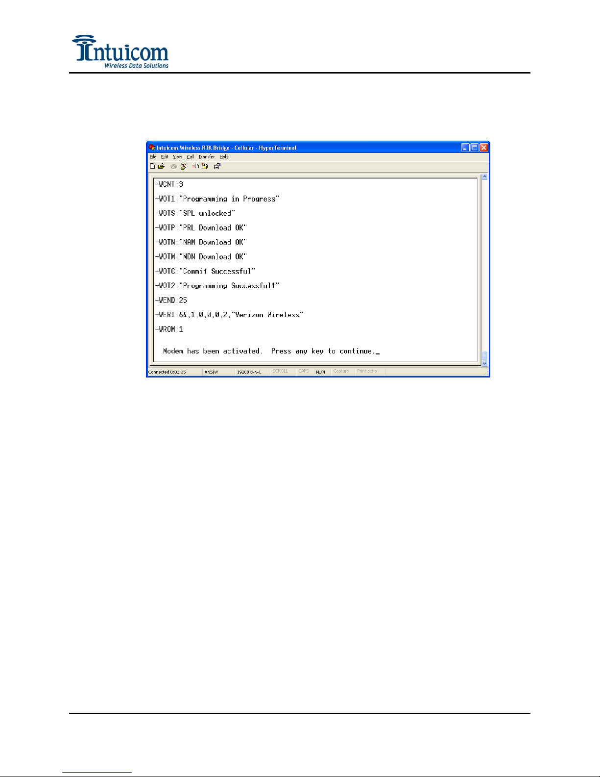
The activation process takes approximately one to two minutes to complete. Success or
failure will be displayed on the screen after the process is complete.
Figure 2-8: Successful Verizon Activation
Revision 1.4 12 © 2009 Intuicom, Inc.
Page 17
Section 2: Initialization and Configuration
2.2.2 GSM/GPRS/EDGE Service
Establishing Service
Contact your selected GSM/GPRS/EDGE provider (AT&T Wireless, or T-Mobile in the
USA) to establish and account and/or add a line of service for this device. Most carriers
have a basic data plan with a 5GB/month data limit. Note: used 24x7 with a 1 Hz
RTCM3 correction, an RTK Bridge should use ~ 2GB/month of data.
Carrier Contact Information Plan Name(s)
www.attwireless.com
AT&T Wireless
888-333-6651 (Consumer)
866-429-7222 (Business)
T-Mobile
www.tmobile.com
877-353-3614
The representative may request the type of device or model number – this too can be
found on the Cellular Configuration menu – the model number is “MTSMC-E”. This
model number allows the carrier to verify this modem as one of its approved models.
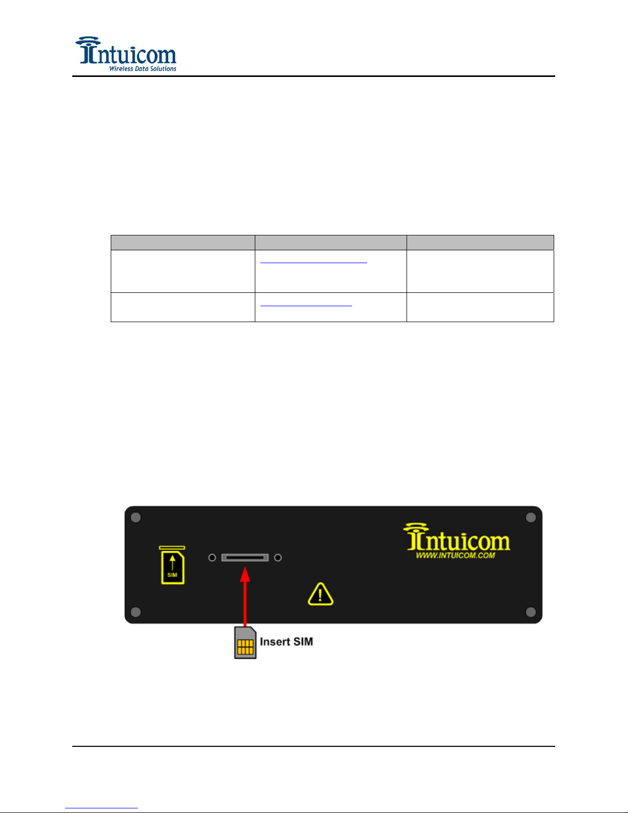
GSM/GPRS/EDGE service requires the use of a SIM card. Typically your SIM card will
be mailed to you (if service was established in person, you will handed a SIM card). The
SIM card must be inserted in the slot on the back panel of the unit. The SIM card must
be inserted while operating the unit.
Data Connect 5GB
webConnect Data Plan
Revision 1.4 13 © 2009 Intuicom, Inc.
Page 18
Section 2: Initialization and Configuration
SIM PIN Configuration
If your SIM card has a PIN number established, the SIM PIN feature can be activated and
the PIN number entered. Use caution in entering the PIN number. The RTK Bridge will
test the PIN after it has been entered to confirm it is correct. The RTK Bridge will
attempt to avoid exceeding the maximum number of PIN attempts if an incorrect PIN has
been entered (for example, the SIM card has been swapped, but the PIN not updated). If
the maximum number of incorrect SIM PIN attempts has been exceeded it will be
necessary to contact the carrier to request a PUK code – in this case the SIM will need to
be removed and inserted into a mobile phone to complete the PUK code entry process.
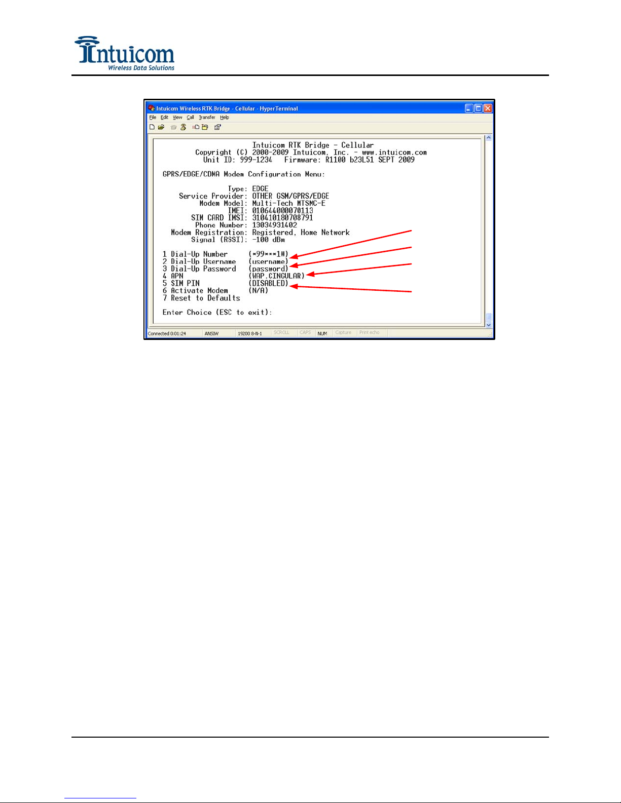
APN, USERNAME, PASSWORD Configuration
GSM/GPRS/EDGE carriers require configuration of an APN (Access Point Name) and
sometimes a username and password field. These parameters are unique to each carrier
and must be configured before use. The Modem menu allows for configuration of these
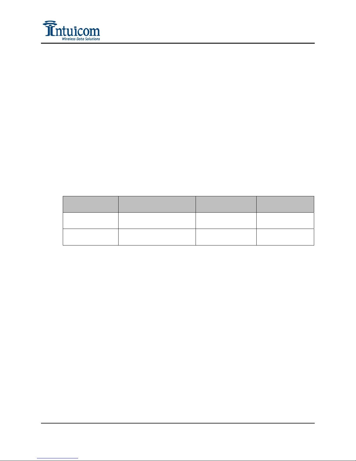
parameters. Parameters for AT&T and T-Mobile are:
Carrier
AT&T
T-Mobile
Available APN
Name(s)
ISP.CINGULAR
WAP.CINGULAR
epc.tmobile.com
internet2.voicestream.net
Username Password
username password
guest guest
Table 2-1: GPRS/EDGE APN, Username, Password
Every GSM/GPRS/EDGE provider will have their own unique settings for APN,
Username and Password. These values can typically be found by searching the support
pages for the carrier, and alternatively various websites have accumulated lists of these
settings for carriers worldwide. Contact Intuicom for additional assistance locating the
appropriate APN for your carrier.
Revision 1.4 14 © 2009 Intuicom, Inc.
Page 19
Section 2: Initialization and Configuration
Username
Password
APN
SIM Pin
Figure 2-9: GPRS/EDGE APN, Username, and Password Parameters
Revision 1.4 15 © 2009 Intuicom, Inc.
Page 20

Section 2: Initialization and Configuration
2.3 Configuration Process
The Intuicom RTK Bridge - Cellular stores four configuration “Profiles” of which one can be
active at a time. A Profile contains the necessary parameters for connecting to a data stream
of RTK correction messages.
Prior to configuration, it is helpful to have the following pieces of data available:
• Whether the Correction Server (and TCP port) to which the unit will connect is a
RAW TCP port, or an NTRIP caster
• The IP address and TCP port for the Network Server
• If the port to which the connection stream is connected supports NTRIP, the
mountpoint will need to be specified.
• If authentication is required (for either a RAW or NTRIP connection), and if so,
your username and password
• Based on the type of correction stream to which the unit will be connecting –
determine if a GPS (GGA NMEA) message needs to be sent and if so, should the
message be generated in real-time from the embedded GPS, be supplied from an
external source via the Data port, or should the message relay a fixed, user supplied
position.
• Whether the embedded Intuicom radio should be enabled, and if so – on which
channel. If a channel needs to be customized, gather the necessary channel
parameters such as Frequency Key, Network ID, Min and Max packet sizes and
whether Repeaters are enabled.
• The baud rate for the Data port on the front panel of the device – this will be the baud
rate needed to interface to a third party external data radio.
The Intuicom RTK Bridge can store one set of the above parameters for each of four Profiles
– allowing the user to select the configuration set to use in the field without the need for a PC
and terminal program. For example: a user may want to have one Profile connect to a
network correction stream and another Profile connect to a single baseline correction from
the nearest reference station and be able to change between the two in the field. Another
example might be the situation where the device is moved between locations and at each
location there is a different external data radio with a different baud rate – while both
locations may want the same correction stream, the Profiles provide an easy way to change
the baud rate for the external data port.
Revision 1.4 16 © 2009 Intuicom, Inc.
Page 21
Section 2: Initialization and Configuration
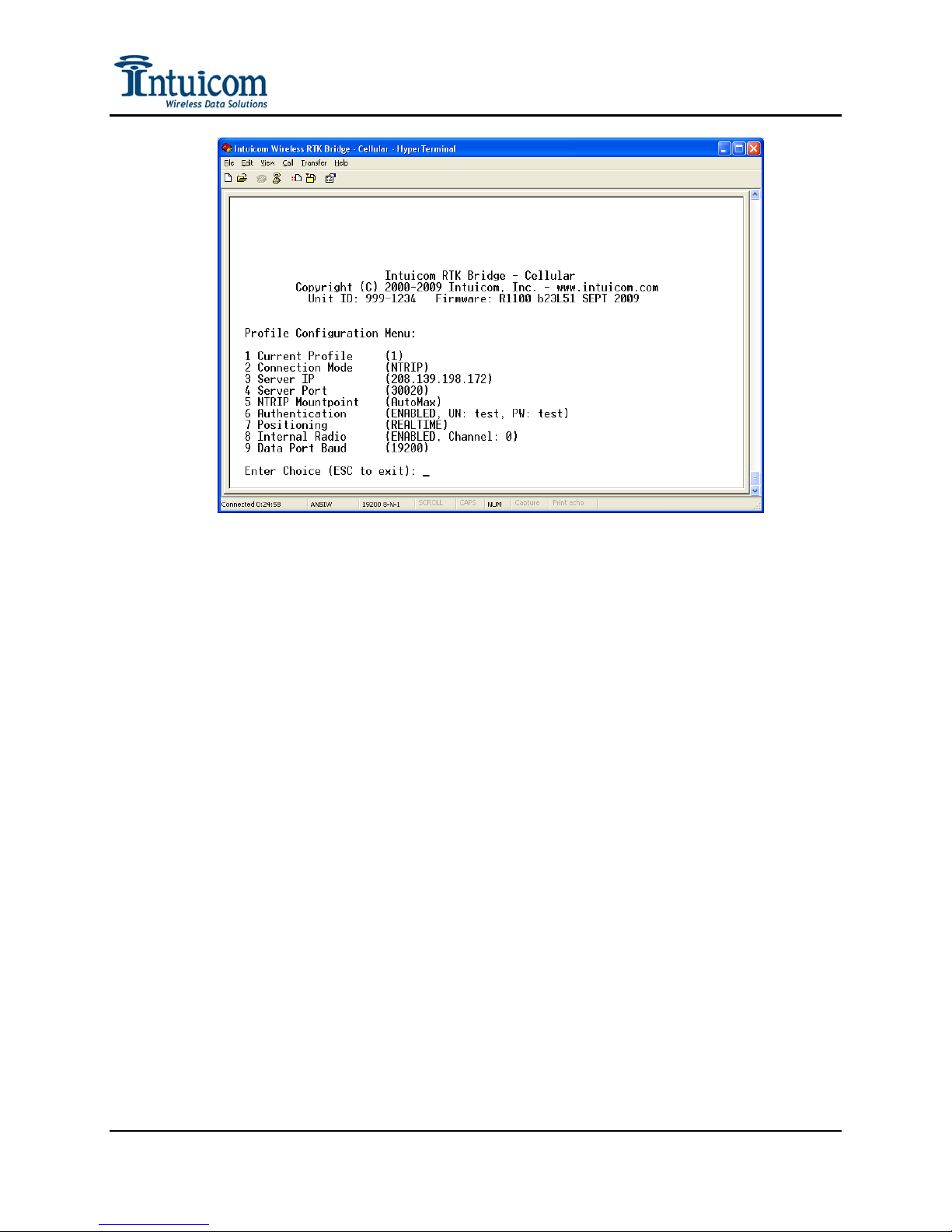
Figure 2-10: Configuration Menu for Profile #1
From the Main Configuration Menu, select Option 1, Profile Configuration. In this menu,
each Profile (1-4) can be selected and/or its parameters configured.
Current Profile – Select Menu Option 1 to change the current Profile. When a given Profile
is selected, its number will be show (1) – (4). Once a Profile is selected, its parameters can
be configured. The parameters from the selected Profile will be used when the unit is
operating. The active profile can also be selected from the front panel of the unit without the
need to use a PC to access the configuration menu. See Operation.
Connection Mode – Select either NTRIP or RAW. In NTRIP mode, the unit will connect to
the IP address and TCP port selected in the following options, and attempt to connect to the
user specified mountpoint. If authentication is required, the user supplied username and
password will be used. In RAW mode, the unit will perform a simply TCP socket connection
to the IP address and TCP port specified in the following options. If authentication is
enabled, the unit will send the $GPUID string at regular intervals populated with the user
supplied username and password.
Server IP – Enter the IP address (x.x.x.x) of the GNSS network server (e.g. Spider, VRS,
etc) to which the unit will attempt a connection. Be carefully to enter the IP address
correctly.
Server Port – Enter the TCP port number on the GNSSnetwork server to connect to.
Typically the TCP port number will have been provided with the server IP address.
Revision 1.4 17 © 2009 Intuicom, Inc.
Page 22
Section 2: Initialization and Configuration
NTRIP Mountpoint – If using NTRIP connection mode, specify the mountpoint (correction
stream) to connect to. Typcially the mountpoint will have been provided along with the IP
address and the TCP port for the GNSS network server. This parameter has no effect if the
connection mode is set to RAW.
Authentication – Specify whether authentication is required for connecting to the GNSS
network server – if so, enter the username and password. Be carefully to enter the username
and password exactly as provided – capitalization typically matters. It can be important to
note that the GNSS server may or may not be configured to allow simultaneous logins with a
given username/password combination – you may need a separate username and password
for each RTK Bridge.
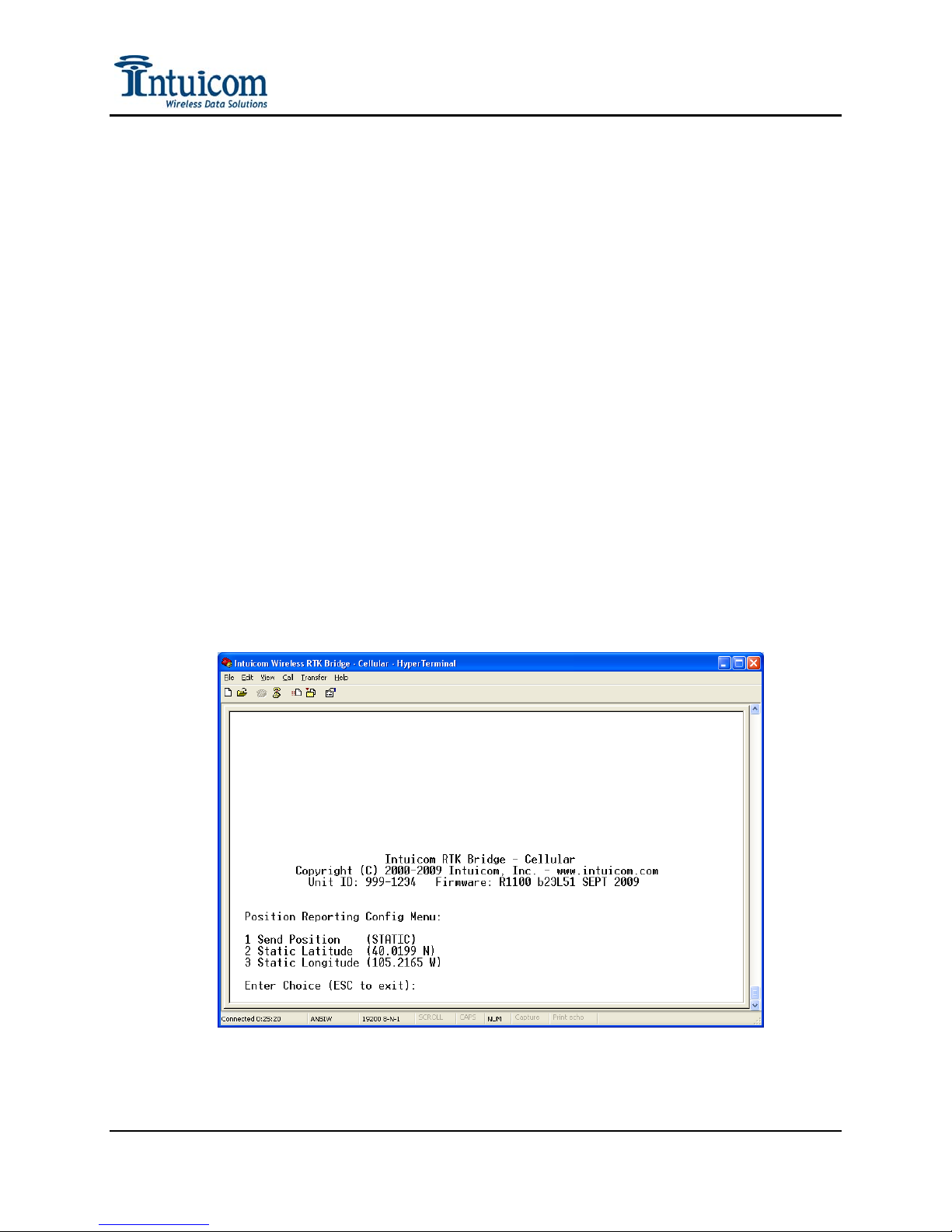
Positioning – When connected to an NTRIP mountpoint, or RAW socket/port, the RTK
Bridge - Cellular can provide a position (GGA NMEA string). A position is often required
for the GNSS network server to be able to generate a stream of network RTK corrections
specific for the user’s location. In most cases the distance between the RTK Bridge’s GPS
antenna and the rover user(s) position is both not great, and not significant in generating the
correction stream. In cases where the rover uses are a significant distance from the RTK
Bridge, a position may be manually entered, and this manually entered position can be sent
instead of the real-time position from the GPS receiver embedded in the RTK Bridge unit.
Specify whether the position to be sent is RealTime (from the embedded GPS) , Static (from
the manually entered position) or Data Port, to forward GGS strings sent to the unit on the
data port. To send no position, select Disabled.
Revision 1.4 18 © 2009 Intuicom, Inc.
Figure 2-11: Positioning Configuration Menu
Page 23
Section 2: Initialization and Configuration
Internal Radio – The internal Intuicom 900MHz spread spectrum data radio can be enabled
or disabled. If enabled, the user can configure and specify which channel to use. This radio
is fully compatible with Intuicom 1200 Data Link radios, as well as Intuicom Communicator
II radios. Contact Intuicom for assistance with custom radio configurations for backwards
compatibility to existing radio networks. When the radio is disabled (for example in the case
where only a third party external radio will be used) the radio is actually powered down to
conserve battery life.
The wireless configuration interface is designed to be identical to that of the Intuicom
1200 Data Link, where “channels” are configured with spread spectrum parameters
(Frequency Key, Network ID, Min/Max Packet Sizes, Repeaters) – and a specific
“channel” is selected. If these channels are configured identically to the configuration for
existing 1200 Data Link units, all that is required for communications is making sure
both devices have the same “channel” selected.
Each “Channel” represents a set of spread spectrum configuration parameters. For a
given remote unit to link and receive data, it must have a channel configuration that
matches the configuration of RTK Bridge’s currently selected channel.
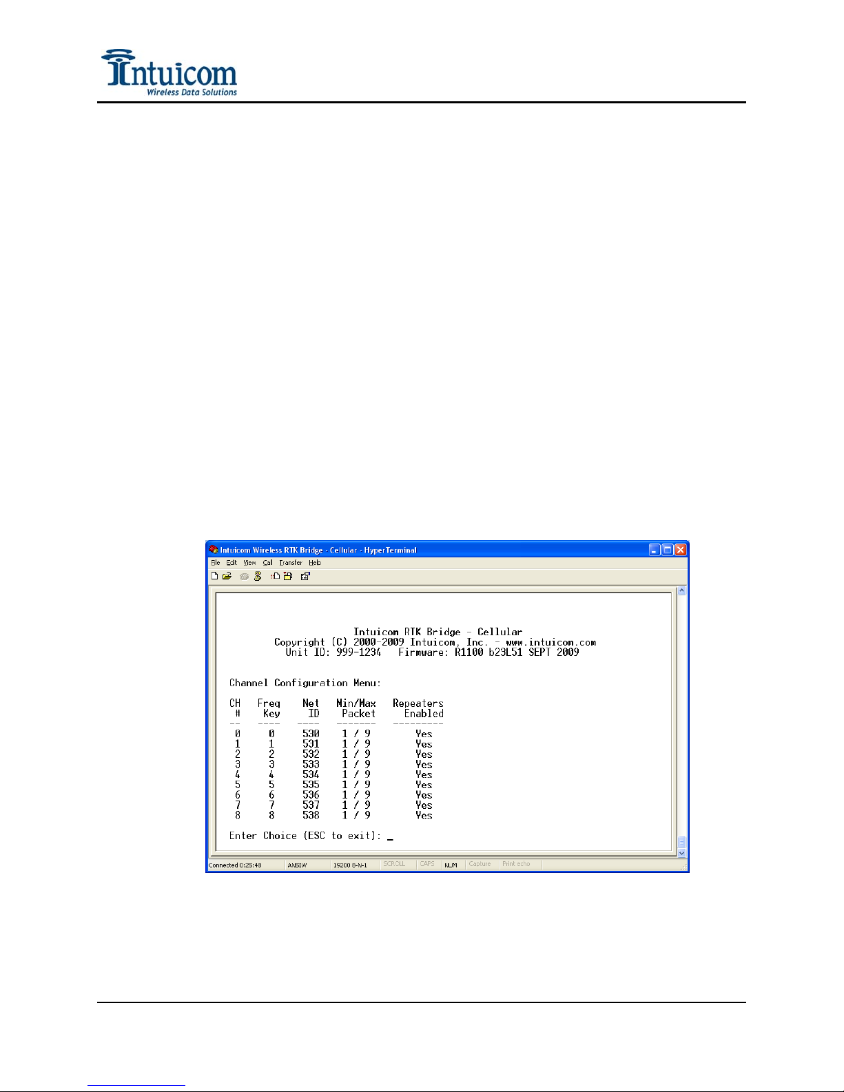
Channels Internal Radio “Channels” can be customized by selecting Option 2 from the
Main Configuration Menu.
Figure 2-12: Internal Radio Channel Configuration Menu
Frequency Key (Freq Key) – a number between 0 and 14. Each number represents a
different pseudo-random frequency hopping pattern. For two radios to communicate,
they must have the same Frequency Key.
Revision 1.4 19 © 2009 Intuicom, Inc.
Page 24

Section 2: Initialization and Configuration
Network ID (Net ID) – a number between 1 and 4000. (note a value of 255 is not
allowed). This arbitrary number uniquely identifies a wireless network. For two radios
to communicate they must have the same Network ID.
Min/Max Packet – two numbers between 1 and 9. The Min and Max packet size values
control latency vs. throughput tradeoff in the wireless network. Like the Frequency Key
and Network ID parameters, for two given radios to communicate, they must have
matching values for their respective Min and Max Packet sizes. It is recommended to
leave the default values of 1 for Min and 9 for Max unless a specific application
requirement dictates otherwise.
Repeaters Enabled – Yes or No. Indicates whether Repeaters or Rover Repeaters might
be used on this channel. If Repeater(s) will be utilized set the value to YES. All radios
in a given network must have the same value for the Repeaters Enabled parameter to be
able to communicate. It is recommended to leave the default value of Yes unless a
specific application dictates otherwise. Contact Intuicom for more information about
configuring repeaters.
Data Port Baud – Set the RS232 baud rate for the Data Port on the front panel of the unit. If
using an external third-party data radio, this baud rate must match the baud of the external
radio. Data is present on this port regardless of the baud rate or whether a connection is
made to another radio. For testing, this port could be connected directly to a GPS Rover.
Revision 1.4 20 © 2009 Intuicom, Inc.
Page 25
PARAMETER
Mode (RAW/NTRIP)
Server IP
Server TCP Port
Mountpoint Name
Authentication
Username
Password
GPS Mode
Latitude
Longitude
Internal Radio Enabled
Internal Radio Channel
Data Port Baud
Section 2: Initialization and Configuration
PROFILE
1 2 3 4
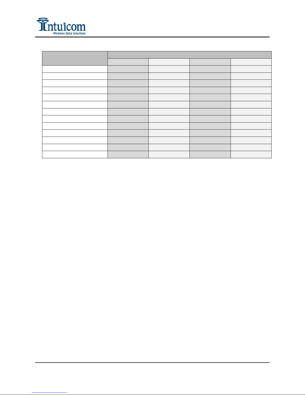
Table 2-2: Profile Configuration Table
Revision 1.4 21 © 2009 Intuicom, Inc.
Page 26
Section 2: Initialization and Configuration
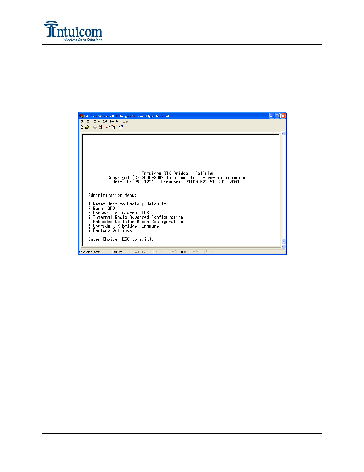
2.3.1 Administrative
Main Menu Option 3 – the Administration Menu – provides options for unit maintenance
and advanced wireless configuration. For most applications it is not necessary to utilize
the Administrative configuration parameters.
Reset Unit to Factory Defaults - Select this option to reset all configuration parameters
including the internal wireless data radio and GPS back to the factory default settings.
Reset GPS - Select this option to force the GPS to clear its ephemeris and almanac and
perform a cold start / sky search. Select this option if the GPS is experiencing issues, or
is taking a considerable time to track in otherwise good conditions (good antenna, good
sky view).
Connect to Internal GPS – This option allows one to be directly connected to the realtime output of the embedded GPS receiver. This is helpful to determine if the GPS
receiver is tracking – for example when testing different GPS antennas or antenna
locations.
Internal Radio Advanced Configuration - Select this option for access to Advanced
Wireless configuration. The Advanced wireless configuration allows the internal
wireless data radio to be fine tuned for compatibility with a range of Intuicom Wireless
Data Transceiver products, and for specific wireless configuration to address a location
specific condition (like lowering the transmit power, or avoiding in-band interference).
Revision 1.4 22 © 2009 Intuicom, Inc.
Page 27

Section 2: Initialization and Configuration
Use the Radio Advanced Configuration to modify such parameters as setting the
appropriate HOP table for the country/regulatory domain in which the unit will operate.
Warning: random changes to the wireless data radio configuration parameters can
render the wireless configuration incompatible with receiving units. Contact Intuicom
for guidance configuring the unit for specific needs. Be exceptionally careful not to
change the setting for “Setup Port” – doing so could require returning the unit to
Intuicom for reset.
Embedded Cellular Modem Configuration – This option is used with first
initializing/provisioning the internal modem. This option can also be used to view the
current signal strength and registration status. It is further possible to modify the default
parameters for the dialup number, username, password and APN. It is recommended not
to change any of these parameters from their defaults.
Upgrade RTK Bridge Firmware – This option allows the unit’s base firmware to be
upgraded or downgraded. Contact Intuicom for the latest firmware and the firmware
upgrade utility.
Revision 1.4 23 © 2009 Intuicom, Inc.
Page 28
Section 3: Operation
3 Operation
The Intuicom Wireless RTK Bridge unit must be properly configured before operation. See
Section 2 for information about how to configure a unit prior to use. Once configured, and
physically setup for operation, the unit will go through a startup routine when powered on,
connect to the GNSS network server, and begin broadcasting corrections.
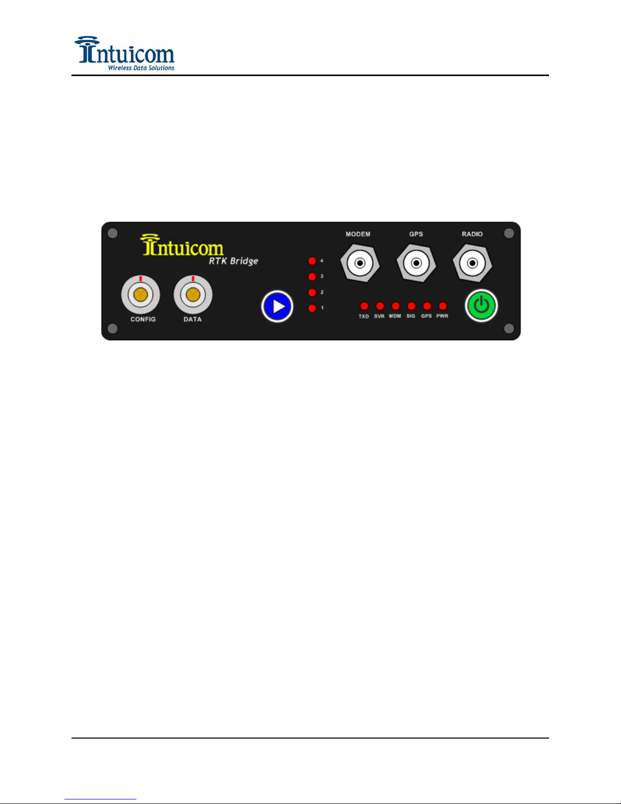
Figure 3-1: RTK Bridge - Cellular Front Panel
3.1 Basic Steps for Operation
1. Connect Wireless Data Antenna – Connect an appropriate data antenna to the TNC
RADIO connector on the front of the unit (Labeled 9 in Figure 3-1). The antenna could
be an omni-directional antenna or a directional yagi antenna. Typically there is a
segment of cable between the unit and the antenna. Suggested cable types include Times
Microwave LMR240 and LMR400 with TNC and N-Type connectors. Contact Intuicom
for more information about antennas and cabling. Position the antenna to provide the
best coverage for your application. In general, antenna height makes a significant
difference in range and performance. “Height is everything.”
2. Connect GPS Antenna – If the configuration utilizes the embedded GPS to obtain a
correction stream, be sure to attach the included L1 GPS antenna to the TNC connector
on the front panel (Labeled 8 in Figure 3-1) and position the antenna such that it has good
visibility to the sky.
3. Connect Modem (Cellular) Antenna – Connect the appropriate Cellular antenna to the
Modem antenna connector on the front panel (Labeled 7 in Figure 3-1). This antenna
will be the included “duck” antenna or an optional directional panel antenna. If the unit
is located in weak wireless coverage, a directional panel antenna may be necessary to
successfully connect to the network. See Cellular Modem Antenna Aiming Mode in
Section 3.5.
Revision 1.4 24 © 2009 Intuicom, Inc.
Page 29
Section 3: Operation
4. Connect to Data Port for copy of correction stream (optional) – If copies of the
correction are to be broadcast using an external third-party base radio, connect the
included Power/Data cable can be used. A null modem or gender changer may be
required. Intuicom manufactures dedicated cables for connections to some external
radios, eliminating the need to connect DB9 ends together. It is also possible to connect
directly to an RTK Rover GPS for testing.
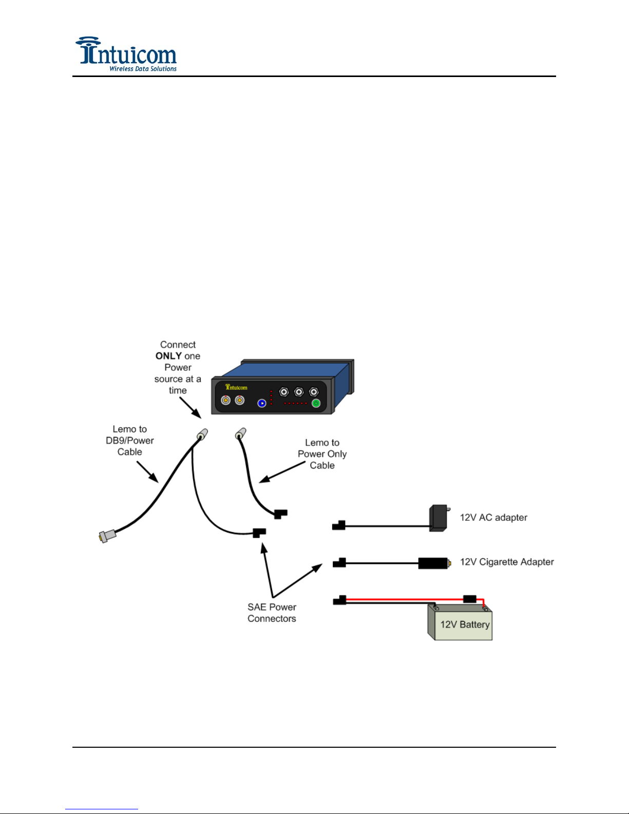
5. Connect Power – Power can be applied to either the Config or the Data port but not both
– be sure power is only being applied to one port. Power is applied using the power only
cable, the power pigtail on the power/data cable, or the power pigtail from one of the
RTK Bridge to external radio cables. CAUTION: Only apply power from one source!
Connect 10-24 VDC power to the front panel using the included power adapter or using
the optional power pigtail. Power could be supplied from an AC adapter, a battery or a
car cigarette lighter adapter.
Figure 3-2: Power Connection options for the RTK Bridge
6. To power on the unit, press and hold green power button (Labeled 6 in Figure 3-1) until
the PWR LED lights red.
Revision 1.4 25 © 2009 Intuicom, Inc.
Page 30
Section 3: Operation
Intuicom
900 M Hz
5dB Omni
Antenna
Intuicom 900 MHz
Spread Spectrum
Wireless Data
LMR240 Coax
Directional
Cellular/3G
Duck Antenna
CDMA/GSM/EDGE
Wireles s Connection
Intuicom RTK
Bridge - Cellular
12V
Battery
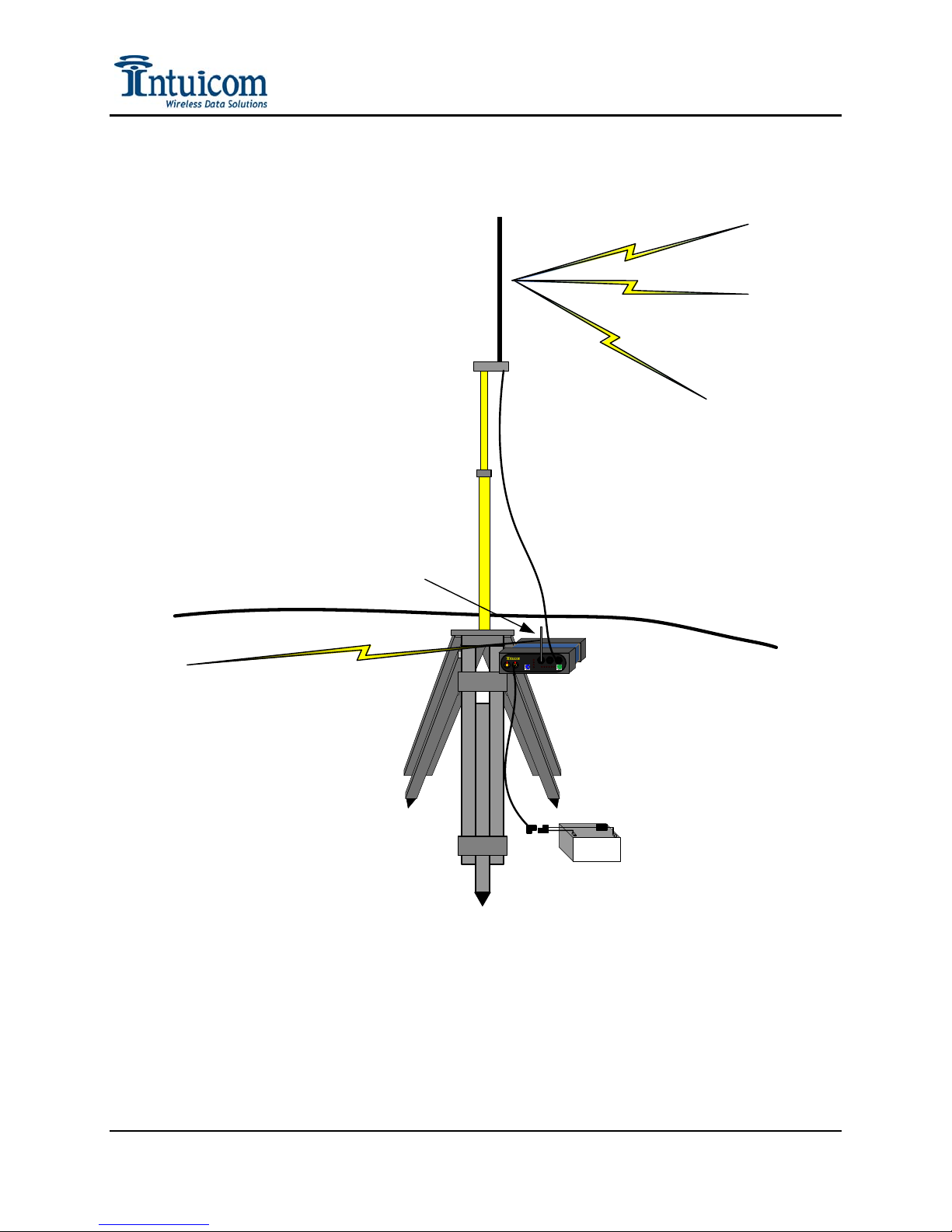
Figure 3-3: Typical RTK Bridge field setup
Revision 1.4 26 © 2009 Intuicom, Inc.
Page 31

Section 3: Operation
3.2 Startup Sequence
Once the unit is properly configured and physically setup it goes through a startup sequence
when power is attached and power button pressed.
1. The PWR LED on the front panel should immediately light RED (If the Profile
Button is held during power up (for about 20 seconds) all Profile (1-4) LEDs will
flash and the unit will enter Antenna Aiming Mode).
2. The currently active profile LED (1-4) will blink – press the Profile button to change
the active Profile at this point. If the Profile is changed, the unit will re-start with the
new Profile.
3. The Cellular signal is sampled – and the SIG light will indicate the current Cellular
signal strength (Solid RED, Flashing RED, or OFF).
4. Assuming the signal strength is sufficient, the embedded cellular modem will registr
with the carrier’s network and the unit will connect to the Internet, a successful
connection is indicated by the MDM light turning RED.
5. The unit will attempt to connect to the Server IP and Port number specified in the
profile, if this connection is successful, the SVR LED will turn RED.
6. If in NTRIP mode, the unit will attempt to connect to the configured mountpoint
using the configured username and password. If this failed, the SVR LED will turn
off.
7. If the unit is configured to send its Real-Time, or Static GPS message, it will do so
within 10 seconds. The GPS LED will indicate if the internal GPS is tracking, or if a
Static GPS message is being sent.
8. The TXD LED will begin to blink as corrections are received and broadcast out the
internal data radio and/or the Data port on the front panel. Operation will continue
until interrupted by power off, or loss of cellular signal.
Revision 1.4 27 © 2009 Intuicom, Inc.
Page 32
Section 3: Operation
3.3 Front Panel LEDs
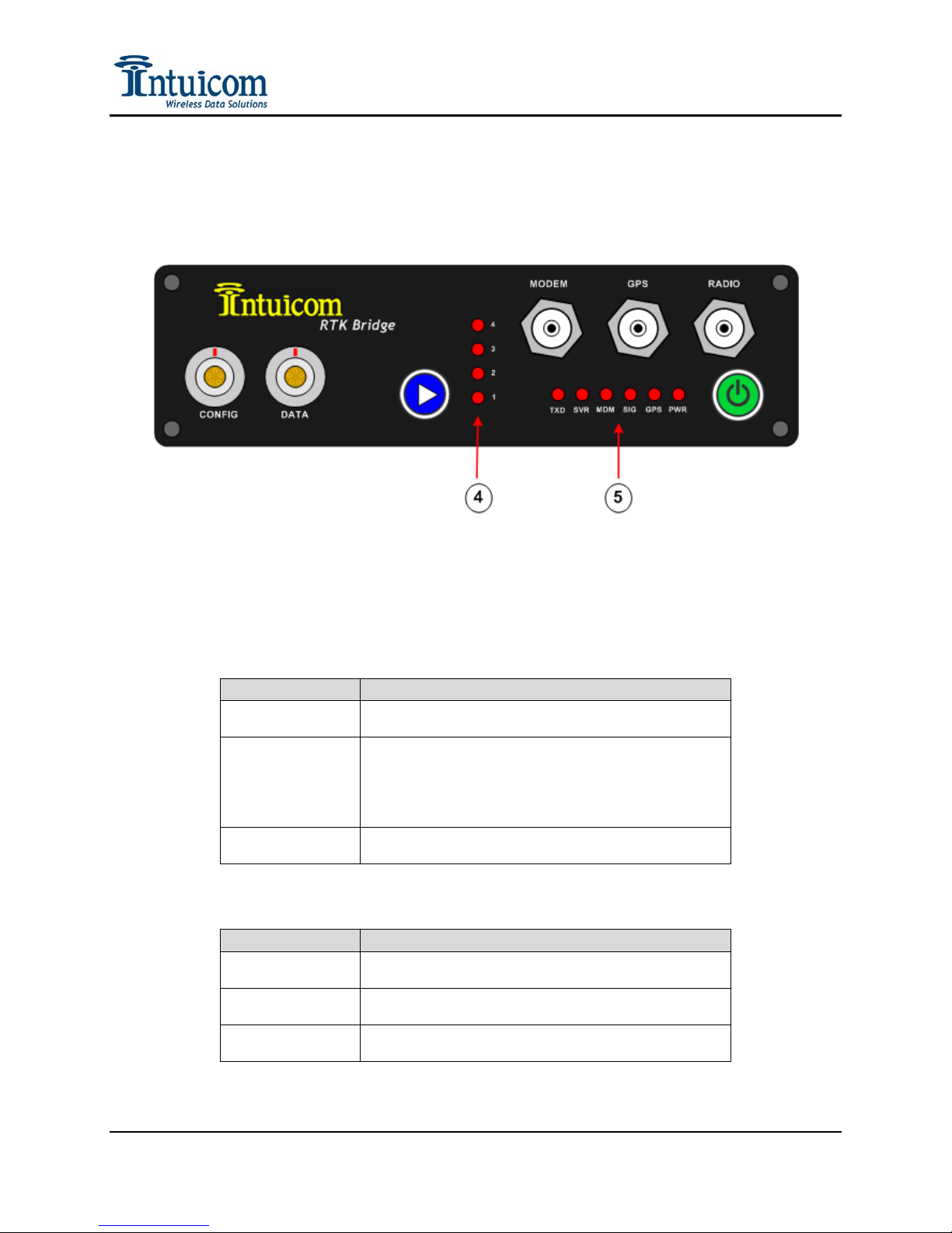
There are eleven red LEDs visible on the front panel (5) and (4).
Figure 3-4: RTK Bridge - Cellular Front Panel
PWR – When illuminated indicates that the unit is powered and has been turned on.
GPS:
LED DESCRIPTION
Solid Red
Flashing Red
Off
Internal GPS is selected for use in the current Profile
and is tracking
Internal GPS is selected for use in the current Profile,
and the GPS is not tracking or Data Port is selected to
receive GGA messages from an external GPS and either
these messages are not being received, or the external
GPS is not tracking.
Either a Static position has been selected or the sending
of a GPS position to the server is disabled.
SIG:
LED DESCRIPTION
Solid Red
Flashing Red
Off
Indicates a strong cellular signal as sampled during the
power-up/boot-up stage
Indicates a marginal cellular signal – communication
may or may not be possible.
Indicates a very weak or absent cellular signal – it is
very unlikely communications will be possible.
Revision 1.4 28 © 2009 Intuicom, Inc.
Page 33

Section 3: Operation
MDM – Indicates a successful connection to the carrier’s IP network (and thus the Internet)
SVR – Indicates a successful network connection to the IP socket (either RAW or NTRIP).
TXD – Indicates data being transmitted out the internal Intuicom Wireless Data Radio,
and/or the Data port (2) on the front panel.
1 – 4 –In normal operation, the LEDs labeled 1-4 indicate the currently selected Profile. In
antenna alignment mode, the LEDs are used as a bar graph to indicate cellular signal
strength.
Revision 1.4 29 © 2009 Intuicom, Inc.
Page 34
Section 3: Operation
3.4 Config Port Status Display/Messages
Current operation status can be monitored by connecting to the Config Port on the front panel
using the Data/Power cable and a PC with a terminal application such as HyperTerminal.
Connect to the Config Port and configure the terminal application as explained in Section 2 –
Accessing the Configuration Menu. When the unit is powered up, it will begin operation as
explained in Section 3.2 – Startup Sequence. The current status of the unit is output as
ASCII text on Config Port. A number of different possible messages may appear as they
become applicable.
Status Messages include:
• Status of the Cellular Modem connection to the Internet.
• Status of the TCP socket connection to the server (or NTRIP Caster).
• Status of the GPS Positional Messages – whether or not they are being sent – and if
so, the actual message.
• Status of data received from the server or NTRIP Caster, and its broadcast on the
wireless network.
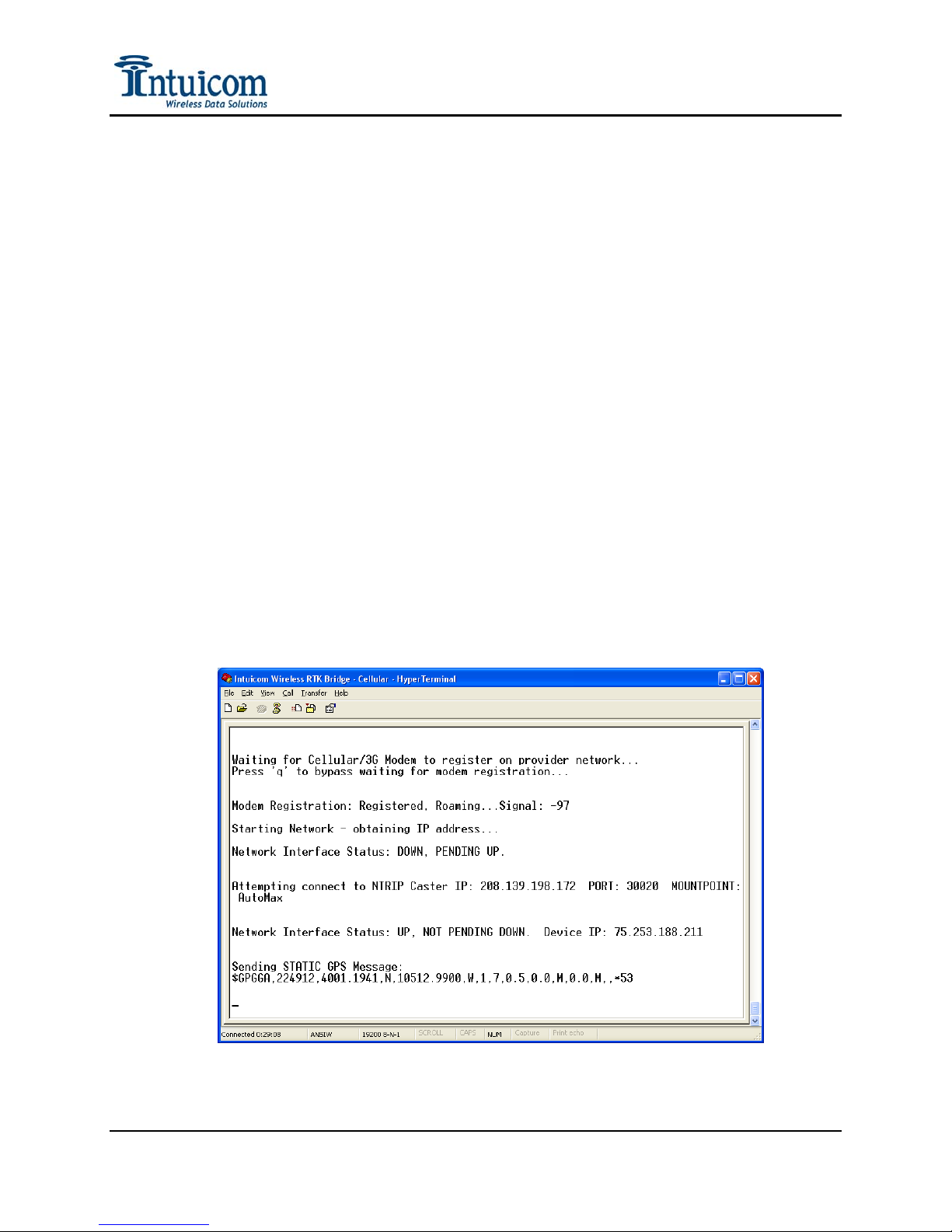
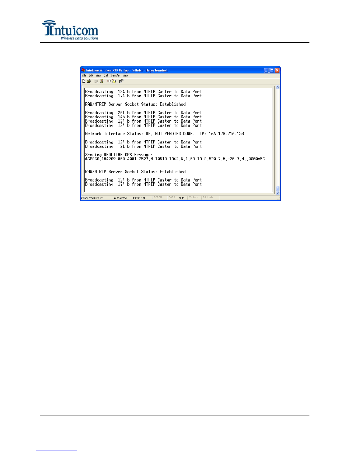
The following screenshots provide example status messages:
Figure 3-5: Example status message output on Config Port
Revision 1.4 30 © 2009 Intuicom, Inc.
Page 35
Section 3: Operation
Figure 3-6: Example status message output on Config Port
Revision 1.4 31 © 2009 Intuicom, Inc.
Page 36
Section 3: Operation
3.5 Antenna Aiming / Cellular Signal Strength Mode
The RTK Bridge - Cellular has a special mode useful when utilizing a directional antenna for
the embedded Cellular modem. A directional antenna is most useful when operating in an
area of weak cellular coverage. The Antenna aiming mode allows the user to see signal
strength feedback from the front panel of the unit while aiming the directional antenna. Once
the signal strength is peaked, the direction antenna can be secured in place.
To enter Antenna Aiming Mode, be sure a directional cellular antenna is attached (often an
outdoor panel antenna – see accessories). Connect power to the unit using the power/data
cable or the power only cable. While holding the blue profile button, power on the unit and
continue holding the profile button until all four profile indicator LEDs (labeled 1-4) flash at
the same time. Release the profile button – the unit is now in Antenna Aiming Mode and
will continue in the mode until the unit is powered down.
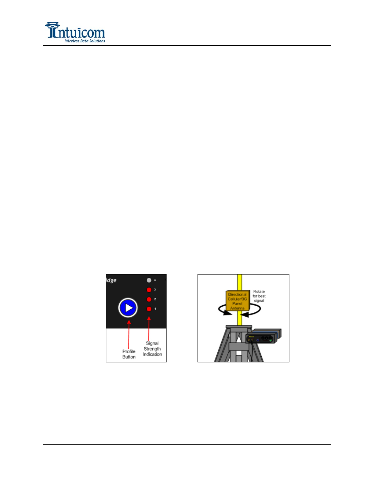
In Antenna Aiming Mode, the profile indicator LEDs (labeled 1-4 on the front panel) will
form a vertical bar graph indicating relative signal strength. When none of the LEDs are
illuminated, it indicates a weak or non-existent signal, while four lit LEDs indicates a very
strong signal.
Rotate the directional antenna while watching the signal strength indication. Identify the
antenna orientation that results in the strongest indicated signal and secure the antenna in that
position. Exit the Antenna Aiming Mode by powering down the unit (press and hold the
green power button until the PWR LED goes out).
Figure 3-7: Cellular signal strength and antenna aimi n g
Revision 1.4 32 © 2009 Intuicom, Inc.
Page 37
Section 3: Operation
3.6 Changing Profiles
The active Profile can be changed in the field without the use of a PC. At least one Profile
must be configured for operation. It is suggested to configure the Profiles in numerical order
– starting with Profile 1.
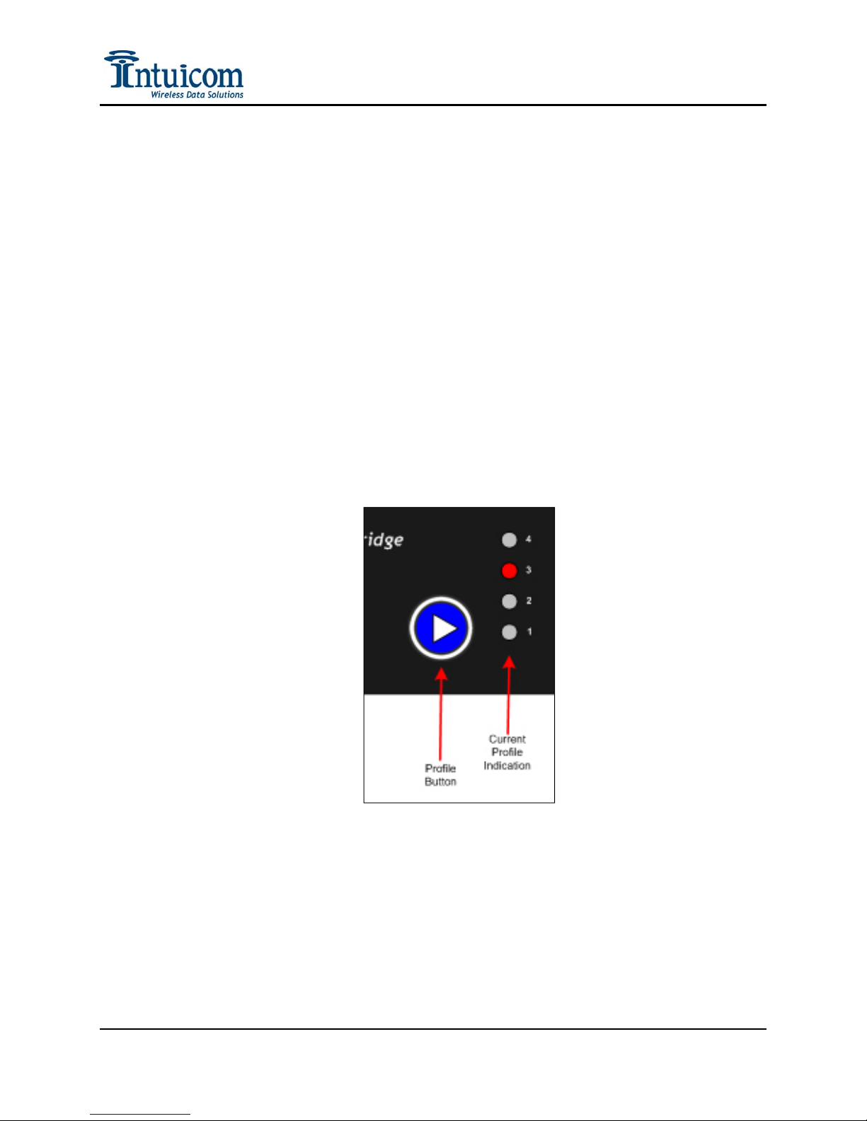
Profiles are changed in the field by pressing the blue Profile button on the front panel at the
appropriate time during the boot up process. To change Profiles, power on the unit and wait
for the currently active profile LED to flash (the profile LEDs are in a vertical column
labeled 1-4 on the front panel). Immediately upon seeing the currently active Profile LED
flash, press the blue profile button – this will result in incrementing the active profile – and
the change will be displayed by the lit Profile LED advancing. Continue to press and release
the blue Profile button until the desired Profile is selected. The unit will timeout waiting for
further changes, then reboot and re-configure for the newly selected active Profile.
The selected active Profile must have been properly configured before being selected. For
information about how to configure the parameters for each individual Profile, see Section
2.3.
Figure 3-8: Changing the active profile on the front panel
Example: A user has two Profiles configured. Each profile is basically the same with
regard to the GNSS network server, and login credentials – the Profiles differ in the
NTRIP mountpoint names. The user wants to be able to switch from an RTCM 3
correction to a Leica message from a specific reference station. The user can change the
RTK Bridge to use the different profile, and change the rover configuration to accept the
different correction message type.
Revision 1.4 33 © 2009 Intuicom, Inc.
Page 38

Section 3: Operation
3.7 Optimizing Wireless Performance
Range performance of the Intuicom 900MHz Spread Spectrum Wireless Data Radio network
can be greatly improved by optimizing the radio location and antenna setup. Height is
everything. If the RTK Bridge and antenna setup can be located at a high-point that
improves line of sight between its antenna and rover units, the performance can be greatly
improved. It may even be desirable to locate the unit farther away, but at a higher location.
Key factors affecting wireless performance:
1) Location and height – In general locating the unit as high as possible and/or using a mast
for the broadcast antenna can greatly improve wireless performance.
Revision 1.4 34 © 2009 Intuicom, Inc.
Page 39

Section 3: Operation
2) Antenna type and proper installation and aiming if applicable – Unless the users are
generally in close proximity to the unit – use of a high gain antenna is desirable. High
gain antennas include a 5 dBi omni-directional antenna and a 10 dBi yagi directional
antenna. For the broadcast radio, if the area to be covered is in a single direction from the
unit, it may be desirable to use a directional antenna to concentrate the antenna gain in
the direction of the user(s).
For the embedded Cellular modem, it may not be adequate to use the included duck
antenna. A higher gain 7 dBi omni-directional antenna as well as a 12 dBi directional
panel antenna is available.
3) Coaxial cable length and type – Keep antenna cables as short as possible. Avoid using
adapters. Use coax that has lower loss for high frequencies – such as Times Microwave
LMR240. Avoid using RG-58 cable.
4) Rover antenna type and condition – confirm that the rover users are using the correct
antenna. Any additional height that can be added to the rover antenna is useful – such as
a backpack with a short pole and adapter for the duck antenna.
Revision 1.4 35 © 2009 Intuicom, Inc.
Page 40
Section 3: Operation
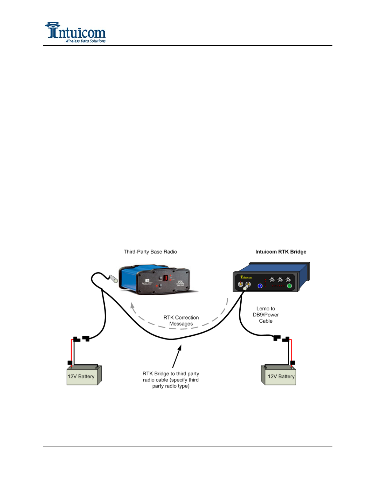
3.8 Connecting to Third-Party Radio
In addition to broadcasting RTK correction messages via the internal Intuicom 900MHz
Spread Spectrum Data Radio (if installed) – the correction messages are available via RS232
on the DATA port on the front panel of the unit and a cable can be used to connect to any
third party radio that accepts data via RS232.
To connect to an external third-party radio:
1. Configure the baud rate of the DATA port on the RTK Bridge to match the baud rate
of the third-party radio.
2. Connect the included Data/Power cable to the Data port on the front of the unit.
3. Connect power to the Data Power cable – being sure that power is only connected to
the unit at one point. Alternatively power could be applied using a different cable on
the Config port – but not both ports simultaneously.
4. Connect the DB9 end of the Data/Power cable to the data cable coming from the
third-party radio. This may require a null modem adapter, and/or a 25 to 9 pin serial
adapter.
5. Power up both units and confirm reception of corrections at rover radios receiving
from the third-party base radio.
Figure 3-9: Connecting to third-party base radio
Revision 1.4 36 © 2009 Intuicom, Inc.
Page 41

Section 4: Troubleshooting
4 Troubleshooting
Issue Possible Cause(s) Solution
No Power LED indicator on Power is not applied
Incorrect power wiring
Non-operable cable assembly
Confirm power-up operation outside
the tractor.
Confirm cable wiring is correct
Replace cable assembly
Unit powers, but SIG LED never lit
or blinking
GPS LED never lights Unit set to STATIC GPS Message
MDM LED never lights Poor Cellular coverage
SVR LED never lights Unit unable to establish TCP
Out of Cellular Coverage
No Cellular antenna attached
Insufficient Cellular antenna for
location
Weak or intermittent signal
Missing or bad GPS antenna
Poor coverage – operating indoors
External GGA message source not
tracking or not sending correct
message(s)
Missing or bad Cellular antenna
Non-activated unit (CDMA)
Non activated unit (GSM)
socket connection to server Incorrect Server Address or Port
Configuration
Confirm operating within carrier’s
coverage area.
Connect adequate Cellular antenna
for location – a directional antenna
may be required in weak coverage
areas.
Move to better coverage or improve
the antenna
Confirm the unit POSITIONING
mode is configured for REALTIME
or DATA PORT.
Confirm a good GPS antenna is
attached to the GPS TNC antenna
port on the front panel – orient the
antenna outdoors with good sky
visibility.
If GPS (GGA) messages are
provided via an external device on
the DATA port, confirm that the
device is actually sending messages
and that its GPS is tracking, baud rate
on data port
Confirm operating within the
carrier’s coverage area.
Confirm good and adequate Cellular
antenna is attached, and if applicable,
oriented.
Confirm unit has been successfully
activated. Also confirm correct
carrier log-in parameters (user name,
password, etc.)
Confirm an active SIM is inserted
and APN parameters correctly
configured.
Configure Server IP Address and
Port
Revision 1.4 37 © 2009 Intuicom, Inc.
Page 42

Section 4: Troubleshooting
Issue Possible Cause(s) Solution
SVR LED blinks on-off slowly
(Unit appears to connect, but the
SVR light goes on and off for a
period before the MDM light goes
off and the unit reboots).
SVR LED on, but no TXT LED and
then reboots.
(Unit unable to connect to NTRIP
mountpoint – source table
continuously displayed (via Config
port status output) )
SVR LED on, but no TXT LED
Unit able to establish connection to
TCP port, and to configured
mountpoint, but no correction
messages are streamed
Incorrect username and/or
password
Username already in use on GNSS
server and GNSS server configured
to not allow multiple simultaneous
logins
Incorrect mountpoint configuration Select valid NTRIP mountpoint
Valid GPS stream required to be
sent to server to obtain corrections
No data available from server
Obtain the correct username and
password for your account on the
GNSS server.
Obtain another username/password
(account) or request the GNSS server
administrator allow multiple
simultaneous logins for your
username/password
Turn on the Sending of GPS
messages to server
Confirm correction server is
operational and capable of outputting
corrections on selected
port/Mountpoint
TXT LED is blinking (correctly) but
the GNSS Rover is not indicating
successful reception of RTK
correction messages
Remote RTK Rover units unable to
establish link via wireless embedded
radio
Remote RTK Rover units link, but
do not receive correction messages
The baud rate between RTK
Bridge and GNSS Rover are
mismatched
The GNSS RTK message type
from the GNSS Server does not
match the message type configured
for the Rover GNSS unit
Channel Configuration incorrect
Wrong channel selected
No antenna, or bad antenna
Correction stream not valid for
Rover configuration
Rover not configured to receive the
correction message type being
broadcast
Confirm proper baud rate on both
devices (matching)
Confirm matching message type on
both sides. Change the message type
on the Rover GNSS unit and/or the
mountpoint from the GNSS Server
Confirm both the RTK Bridge and
Rovers have channel configurations
that match, and have the same
channel selected.
Confirm good antenna/transmission
line
Check correction message type and
rover configuration – either the
correction type on the rover may
need to be changed, or the RTK
Bridge may need to connect to a
different NTRIP mountpoint or
socket.
Revision 1.4 38 © 2009 Intuicom, Inc.
Page 43
Section 5: Accessories
5 Accessories
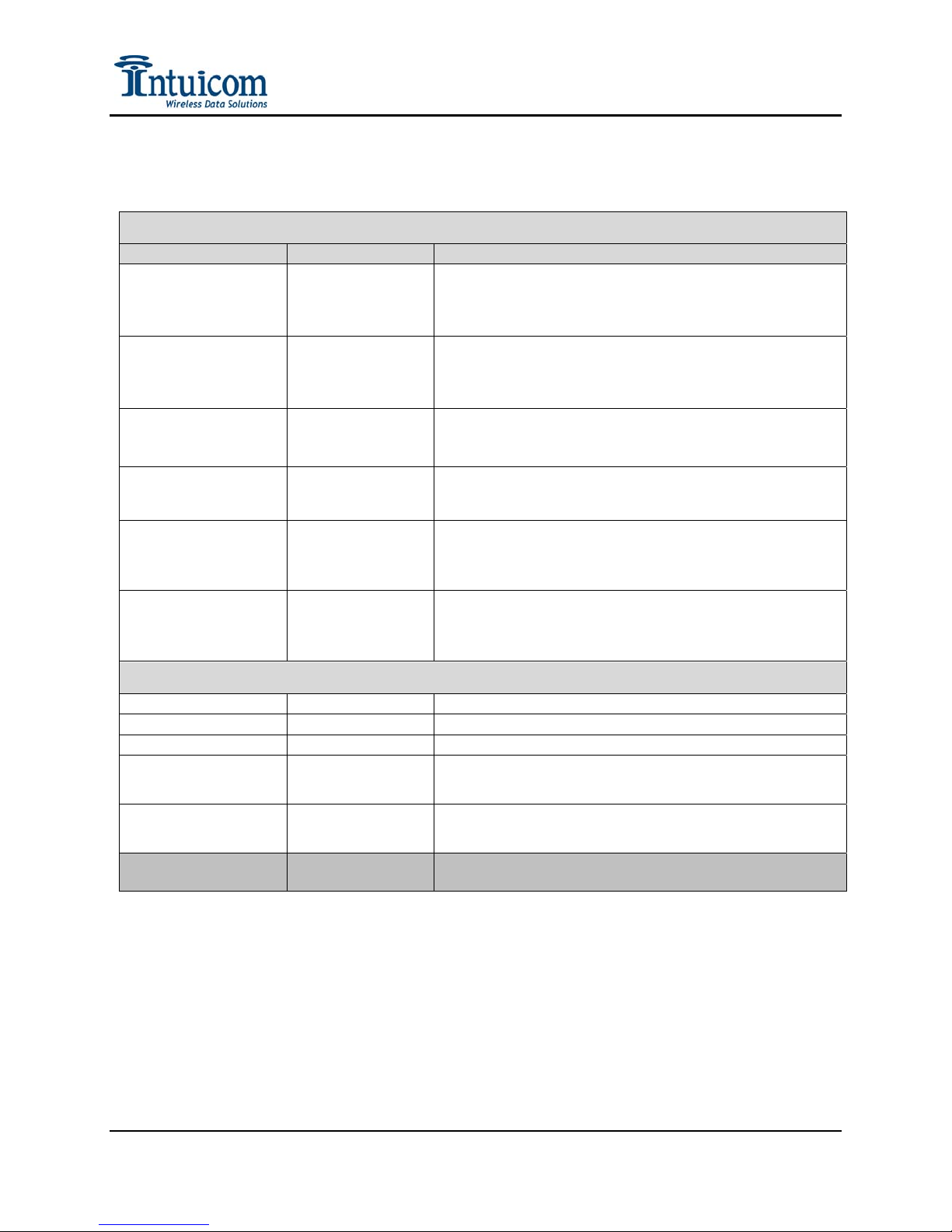
RTK Bridge KITS and Accessories - Typical Survey and Machine control
Product Part Number(s) Description
RTK Bridge
Transceiver Kit with
Verizon modem
RTK Bridge
Transceiver Kit with
AT&T modem
RTK Bridge
Transceiver-Ethernet
Kit
RTK Bridge
Transceiver-Ethernet
Kit (no radio)
RTK Bridge Kit with
Verizon modem (no
radio)
FIP1-900RTK-VKT
FIP1-900RTK-A2KT
FIP1-900RTK-EKT
FIP1-101RTK-EKT
FIP1-101RTK-VKT
Intuicom RTK Bridge with Internal CDMA Modem in Waterproof
Enclosure. Verizon Modem, L1 GPS, 902-928 MHz transceiver, TNC
antenna connectors, two serial interfaces (lemo). Power and data
cables (AC and DC) included with GPS Antenna, Modem Antenna,
Radio Antenna
Intuicom RTK Bridge with Internal GSM Modem in Waterproof
Enclosure. AT&T Modem, L1 GPS, 902-928 MHz transceiver, TNC
antenna connectors, two serial interfaces (lemo). Power and data
cables (AC and DC) included with GPS Antenna, Modem Antenna,
Radio Antenna
Intuicom Bridge & Transceiver for Network RTK Corrections, 902-928
MHz, Embedded GPS, Ethernet interface plus dual serial ports, N-type
RF connector, TNC GPS connector. Kit includes GPS and 900 MHz
antenna.
Intuicom Bridge & Transceiver for Network RTK Corrections,
Embedded GPS, Ethernet interface plus dual serial ports, N-type RF
connector, TNC GPS connector. Kit includes GPS antenna.
Intuicom RTK Bridge with Internal CDMA Modem in Waterproof
Enclosure. Verizon Modem, L1 GPS, TNC antenna connectors, two
serial interfaces (lemo). Power and data cables (AC and DC) included
with GPS Antenna, Modem Antenna.
RTK Bridge Kit with
AT&T modem (no
radio)
FIP1-101RTK-AKT
Intuicom RTK Bridge with Internal GSM Modem in Waterproof
Enclosure. AT&T Modem, L1 GPS, TNC antenna connectors, two serial
interfaces (lemo). Power and data cables (AC and DC) included with
GPS Antenna, Modem Antenna.
General Accessories
Base Antenna kit
GPS Antenna kit
Auto Power Adapter
Cable Assembly-RTK
Bridge to 35W Pacific
FIP4-900BAK-NN20
FIP4-GPSL1-KT
FIP4-SAECIG
FIP4-RTKCAB-PC35
900 Mhz 5 dB Antenna Kit w/ 5/8-11 mount, 20' cable
L1 GPS antenna and cable (tnc) with 15 foot cable
Standard Auto ligher adapter to ASE power plug
Cable assembly to connect RTK Bridge C to a Pacific Crest 35W PDL,
includes power inputs to both units, Lemo to Lemo connection
Crest
Cable Assembly-RTK
Bridge to Trimble
FIP4-RTKCAB-SNB
Cable assembly to connect RTK Bridge C to a Trimble SNB-XXX,
includes power input (SAE) to RTK Bridge. Lemo to Lemo connection.
SNB-XXX
Cable Assembly-RTK
Bridge to Satel XXXXX
FIP4-XXXX-XXX
Cable assembly to connect RTK Bridge C to Satel UHF radio; includes
power inputs to both units, Lemo to Lemo connection
Revision 1.4 39 © 2009 Intuicom, Inc.
Page 44
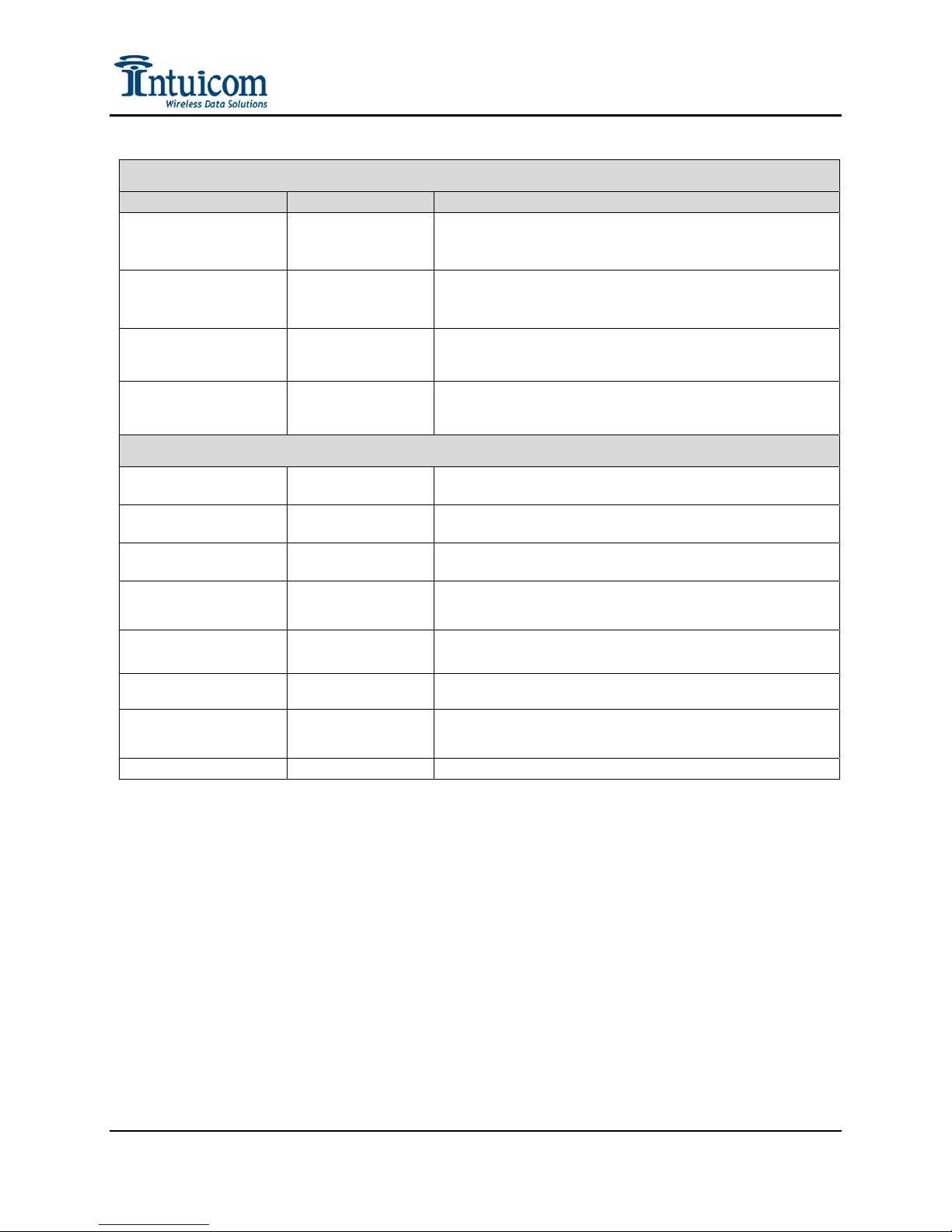
Product Part Number(s) Description
AG- RTK Bridge with
Verizon modem (no
radio)
AG-RTK Bridge with
AT&T modem (no
radio)
AG-RTK Bridge
Transceiver with
Verizon modem
AG-RTK Bridge
Transceiver with
AT&T modem
Dual Mode Antenna magnetic mount
Dual Mode Antenna mirror mount
Dual Mode Antenna stud mount
Cable Assembly-RTK
Bridge to 3rd Party
GPS
252/FMX Cable Kit
EZ-Guide 500 Cable
Kit
Programming Cable
Assembly- RTK
Bridge
Auto Power Adapter
Section 5: Accessories
TRACTOR/AG Applications
Intuicom RTK Bridge with Internal CDMA Modem in Waterproof
FIP1-101RTK-VAG
FIP1-101RTK-AAG
FIP1-900RTK-VAG
FIP1-900RTK-AAG
TRACTOR Mounting Accessories
FIP4-MMDM-MAX-
ANT
FIP4-MRDM-MAX-ANT
FIP4-SMDM-MAX-ANT
FIP4-RTKCAB-UNF
FIP4-RTKCAB-UNF2
FIP4-RTKPWDATA-EZ
FIP4-RTKPWDATA
FIP4-SAECIG
Enclosure. Verizon Modem, L1 GPS, TNC antenna connectors, two
serial interfaces (lemo). Auto power-on. (ON BOARD
APPLICATIONS)
Intuicom RTK Bridge with Internal GSM Modem in Waterproof
Enclosure. AT&T Modem, L1 GPS, TNC antenna connectors, two
serial interfaces (lemo). Auto power-on. (ON BOARD
APPLICATIONS)
Intuicom RTK Bridge with Internal CDMA Modem in Waterproof
Enclosure. Verizon Modem, L1 GPS, 902-928 MHz transceiver, TNC
antenna connectors, two serial interfaces (lemo). Auto power-on.
Intuicom RTK Bridge with Internal GSM Modem in Waterproof
Enclosure. AT&T Modem, L1 GPS, 902-928 MHz transceiver, TNC
antenna connectors, two serial interfaces (lemo). Auto power-on.
Dual mode, hi-gain cellular-GPS magnetic mount antenna assembly,
TNC connnectors, 15-foot length
Dual mode, hi-gain cellular-GPS mirror mount antenna assembly, TNC
connnectors, 15-foot length
Dual mode, hi-gain cellular-GPS stud (through-hole) mount antenna
assembly, TNC connnectors, 15-foot length
Cable assembly to connect RTK Bridge C to a 3rd party GPS device,
Lemo to unfinnished connection, 15-foot length.
Cable assembly to connect RTK Bridge C to a 3rd party GPS device,
Lemo to unfinnished connection, ASE connector to VDC, 15-foot
length.
Cable assembly to power and program the RTK Bridge C, Lemo to
SAE and DB-9; includes DC adapters
Cable assembly to power and program the RTK Bridge C, Lemo to
SAE and DB-9; includes AC adapter
Standard Auto lighter adapter to ASE power plug
Revision 1.4 40 © 2009 Intuicom, Inc.
Page 45

Section 6: Technical Support
6 Technical Support
Contact Intuicom:
email: [email protected]
phone: 303-449-4330 – request technical support for the RTK Bridge - Cellular.
Revision 1.4 41 © 2009 Intuicom, Inc.
Page 46

Section 7: FCC Notification
7 FCC Notification
This device complies with part 15 of the FCC rules. Operation is subject to the following two
conditions: 1) This device may not cause harmful interference and 2) this device must accept any
interference received, including interference that may cause undesired operation. This device
must be operated as supplied by Intuicom, Inc. Any changes or modifications made to the device
without the express written approval of Intuicom may void the user's authority to operate the
device.
CAUTION: The 900MHz Wireless RTK Bridge models have a maximum transmitted output
power of 955mW. It is recommended that the transmit antenna be kept at least 23 cm away from
nearby persons to satisfy FCC RF exposure requirements.
The 2.4GHz Wireless RTK Bridge models have maximum transmitted output power of 500mW.
It is recommended that the transmit antenna be kept at least 23 cm away from nearby persons to
satisfy FCC RF exposure requirements.
This equipment has been tested and found to comply with the limits for a Class B digital device,
pursuant to part 15 of the FCC Rules. These limits are designed to provide reasonable protection
against harmful interference in a residential installation. This equipment generates, uses, and can
radiate radio frequency energy and, if not installed and used in accordance with the instructions,
may cause harmful interference to radio communications. However, there is no guarantee that
interference will not occur in a particular installation. If this equipment does cause harmful
interference to radio or television reception, which can be determined by turning the equipment
off and on, the user is encouraged to try to correct the interference by one or more of the
following measures:
• Reorient or relocate the receiving antenna.
• Increase the separation between the equipment and receiver.
• Connect the equipment into an outlet on a circuit different from that to which the receiver
is connected.
• Consult the dealer or an experienced radio/TV technician for help.
Note: Whenever any Intuicom module is placed inside an enclosure a lab el must be placed on
the outside of that enclosure which includes the module's FCC ID.
Revision 1.4 42 © 2009 Intuicom, Inc.
Page 47

Section 8: Warranty
8 Warranty
LIMITED WARRANTY TO END-USERS
Intuicom, Inc.
1880 South Flatiron Ct., Suite R
BOULDER, CO 80301
A. Standard Limited Warranty for Software Products
limited warranty to the End User that the software will perform substantially in accordance with the accompanying written
materials and that the transfer media on which the Product is provided will be free from defects in materials or workmanship
under normal use and service for a period of ninety (90) days from the date of delivery (the "Limited Warranty") pursuant to
the software license included with the Product. The software license specifically disclaims all other warranties relating to the
Products, including any and all other warranties with respect to the performance of the Products.
B. Hardware and Other Equipment Manufactured By Intuicom
limited warranty for defects in materials or workmanship under normal use and service for a period of one (1) year from the
date of delivery. Intuicom, at its sole discretion, will repair or replace hardware covered under this limited warranty.
Cables, antennas or other accessories manufactured by INTUICOM include a limited warranty for defects in materials or
workmanship under normal use and service for a period of ninety (90) days from the date of delivery. Repairs not covered
under this limited warranty will be billed as set forth in INTUICOM’s current Hardware Service Policy and Instructions.
C. Hardware Manufactured By Others. INTUICOM makes no warranties whatsoever with respect to Hardware manufactured
by third parties. Customers shall look only to the original manufacturer of the Hardware, pursuant to the terms of any
manufacturer warranty for any alleged defects and indemnifies and holds INTUICOM harmless from and against any claims
by any party related directly or indirectly to any defects in the Hardware, and functional failure, improper operation, failure
to operate according to specifications or any other matter related to the Hardware. INTUICOM shall not be liable or
responsible for the failure of the Manufacturer to perform under or honor any warranty with respect to the Hardware.
Customer acknowledges and agrees that Customer shall have the risk of any loss, damage or functional failure related to the
HARDWARE and shall have the responsibility for maintaining the proper operation of the HARDWARE and complying
with all maintenance guidelines and specifications from the Manufacturer and all other conditions to receiving warranty
coverage from the Manufacturer.
D. No Other Warranty
INTUICOM GRANTS NO OTHER WARRANTIES, EXPRESS OR IMPLIED, REGARDING THE PRODUCTS, THEIR
FITNESS FOR ANY PURPOSE, THEIR QUALITY, THEIR MERCHANTABILITY OR OTHERWISE. INTUICOM
DOES NOT MAKE BY VIRTUE OF THIS AGREEMENT OR ANY PRODUCT ORDER, AND HEREBY EXPRESSLY
DISCLAIMS, ANY OTHER REPRESENTATION OR WARRANTY OF ANY KIND WITH RESPECT TO THE
PRODUCTS.
E. Limitation of Liability
CONSEQUENTIAL, INCIDENTAL, BUSINESS INTERUPTION, CATESTROHPIC, PUNITIVE OR OTHER
DAMAGES WHICH MAY BE CLAIMED TO ARISE IN CONECTION WITH ITS PRODU CTS, REGARDLESS OF
THE LEGAL THEORY BEHIND SUCH CLAIMS, WHETHER IN TORT, CONTRACT OR UNDER ANY
APPLICABLE STATUTORY OR REGULATORY LAWS, RULES, REGULATIONS, EXECUTIVE OR
ADMINISTRATIVE ORDERS OR DECLARATIONS OR OTHERWISE, EVEN IF INTUICOM HAS BEEN ADVISED
OR OTHERWISE HAS KNOWLEDGE OF THE POSSIBILITY OF SUCH DAMAGES AND TAKES NO ACTION TO
PREVENT OR MINIMIZE SUCH DAMAGES. IN THE EVENT THAT REGARLDESS OF THE WARRANTY
DISCLAIMERS AND HOLD HARMLESS PROVISIONS INCLUDED ABOVE INTUICOM IS SOMEHOW HELD
LIABLE OR RESPONSIBLE FOR ANY DAMAGE OR INJURY, INTUICOM'S LIABILITY FOR ANY DAMAGES
SHALL NOT EXCEED THE PROFIT REALIZED BY INTUICOM ON THE SALE OR PROVISION OF THE
HARDWARE TO THE CUSTOMER.
. EXCEPT FOR THE EXPRESS STANDARD LIMITED WARRANTY REFERENCED ABOVE,
. IN NO EVENT WILL INTUICOM BE LIABLE FOR ANY INDIRECT, SPECIAL,
. For Products that include a software license, INTUICOM makes a
. Hardware products manufactured by INTUICOM include a
Revision 1.4 43 © 2009 Intuicom, Inc.
 Loading...