

Intuicom NAVIGATOR IIm User Manual

Intuicom®
NAVIGATOR IIm™
Compact Wireless Datalink/GPS Tracker
User Guide
Intuicom, Inc.
1880 S Flatiron Court
Boulder, CO 80301
(303) 449-4330
www.intuicom.com

Navigator IIm User Guide
This manual is for use by purchasers and other authorized users of the Intuicom Products. No
part of this document may be reproduced or transmitted in any form or by any means, electronic
or mechanical, or for any purpose without the express written permission of Intuicom Inc.
© 2000 - 2006 Intuicom Incorporated. All rights reserved.
Intuicom reserves the right to make changes to this manual without notice. Unless otherwise
agreed to in writing, Intuicom assumes no responsibility or liability for the use of this manual or
for the infringement of any copyright or other proprietary right and Intuicom shall deem nothing
contained in this manual a warranty or guarantee.
Intuicom, EB-6 Plus, CommPro, WiGate, Nav-Link, TargeTracker, Intuicom Navigator II,
Navigator IIm and Intuicom Communicator II, Communicator T, 1200 Data Link, and DIO are
trade names of Intuicom, Inc.
Other product names mentioned in this manual may be copyrights, trademarks, or registered
trademarks of their respective companies and are hereby acknowledged.
Revision 1.0a i © 2006 Intuicom Inc.

Navigator IIm User Guide
FCC Notification
This device complies with part 15 of the FCC rules. Operation is subject to the following two
conditions: 1) This device may not cause harmful interference and 2) this device must accept any
interference received, including interference that may cause undesired operation. This device
must be operated as supplied by Intuicom, Inc. Any changes or modifications made to the device
without the express written approval of Intuicom, Inc. may void the user's authority to operate
the device.
CAUTION: The model number FIP1-900N2V-M has a maximum transmitted output power of
955mW. It is recommended that the transmit antenna be kept at least 23 cm away from nearby
persons to satisfy FCC RF exposure requirements.
This equipment has been tested and found to comply with the limits for a Class B digital device,
pursuant to part 15 of the FCC Rules. These limits are designed to provide reasonable protection
against harmful interference in a residential installation. This equipment generates, uses, and can
radiate radio frequency energy and, if not installed and used in accordance with the instructions,
may cause harmful interference to radio communications. However, there is no guarantee that
interference will not occur in a particular installation. If this equipment does cause harmful
interference to radio or television reception, which can be determined by turning the equipment
off and on, the user is encouraged to try to correct the interference by one or more of the
following measures:
• Reorient or relocate the receiving antenna.
• Increase the separation between the equipment and receiver.
• Connect the equipment into an outlet on a circuit different from that to which the receiver
is connected.
• Consult the dealer or an experienced radio/TV technician for help.
Note: Whenever any Intuicom, Inc. module is placed inside an enclosure a label must be placed
on the outside of that enclosure which includes the module's FCC ID.
Revision 1.0a ii © 2006 Intuicom Inc.

Navigator IIm User Guide
This product is licensed by The United States. Diversion contrary to U.S. law
is prohibited. Shipment or re-export of this product outside of The United
States may require authorization by the U.S. Bureau of Export
Administration.
Please contact Intuicom, Inc. for further assistance and information.
Revision 1.0a iii © 2006 Intuicom Inc.

Navigator IIm User Guide
Table of Contents
1 Overview................................................................................................................................1
1.1 General Description........................................................................................................ 1
1.2 Features and Benefits ..................................................................................................... 2
1.3 Common Applications..................................................................................................... 3
1.4 Example Network Architecture....................................................................................... 4
2 Configuration ........................................................................................................................ 5
2.1 Accessing the Navigator IIm Setup Menu....................................................................... 6
2.2 Serial Port Configuration............................................................................................... 7
2.3 GPS Configuration........................................................................................................ 10
2.3.1 Connect To GPS ................................................................................................... 10
2.3.2 Reset GPS – Disable All Output........................................................................... 10
2.3.3 Configure NMEA Output ..................................................................................... 10
2.3.4 Advanced GPS Features ....................................................................................... 13
2.4 Radio Configuration (Wireless Data Transceiver)....................................................... 14
2.4.1 Operation Mode.................................................................................................... 14
2.4.2 Set Baud Rate........................................................................................................ 15
2.4.3 Edit Call Book....................................................................................................... 15
2.4.4 Edit Radio Transmission Characteristics.............................................................. 15
2.4.5 Show Radio Statistics ........................................................................................... 22
2.4.6 Edit Multipoint Parameters................................................................................... 25
2.4.7 TDMA Menu ........................................................................................................31
2.4.8 Chg Password........................................................................................................ 31
2.5 Navigator Configuration............................................................................................... 33
2.5.1 Operation Mode (Master/Slave/Direct/Tracker)................................................... 33
2.5.2 Data Routing Options ........................................................................................... 35
2.5.3 Adaptive Multipoint™ Options............................................................................ 35
2.5.4 Data Packet Configuration.................................................................................... 37
2.5.5 Administration ...................................................................................................... 39
2.5.6 Discrete I/O Configuration ................................................................................... 40
3 Operation............................................................................................................................. 41
3.1 Physical Setup............................................................................................................... 41
3.2 Front Panel LEDs......................................................................................................... 43
3.3 End-to-End Integration using Intuicom Nav-Link........................................................44
4 Pinouts.................................................................................................................................. 45
4.1 Power............................................................................................................................45
4.2 Port A............................................................................................................................ 45
4.3 Port B............................................................................................................................ 45
5 Jumper Settings................................................................................................................... 46
5.1 Power (P6).................................................................................................................... 46
5.2 GPS Antenna (J13) ....................................................................................................... 46
5.3 Port A (J4).....................................................................................................................46
Revision 1.0a iv © 2006 Intuicom Inc.

Navigator IIm User Guide
5.4 Port B (J5).....................................................................................................................47
6 Specifications....................................................................................................................... 48
6.1 General .........................................................................................................................48
6.2 Wireless Transceiver..................................................................................................... 48
6.3 GPS............................................................................................................................... 49
7 Mechanical...........................................................................................................................50
8 Warranty ............................................................................................................................. 51
Revision 1.0a v © 2006 Intuicom Inc.
Section 1: Overview
1 Overview
1.1 General Description
The Intuicom Navigator IIm wireless data transceiver enables wireless connectivity for up
to two external RS232 devices. An optional internal GPS receiver enables position and time
to be included in the wireless data stream as well as be utilized locally. Discrete inputs and
outputs enable remote sensing of states or switch closures as well as remote control.
A Navigator IIm can play many roles in a wireless network including a remote slave, a
slave/repeater or a network master transceiver. Typical applications employ many Navigator
IIm transceivers as slaves wirelessly transmitting data to and from connected RS232 devices
back to a central location where the data is made available via IP sockets.
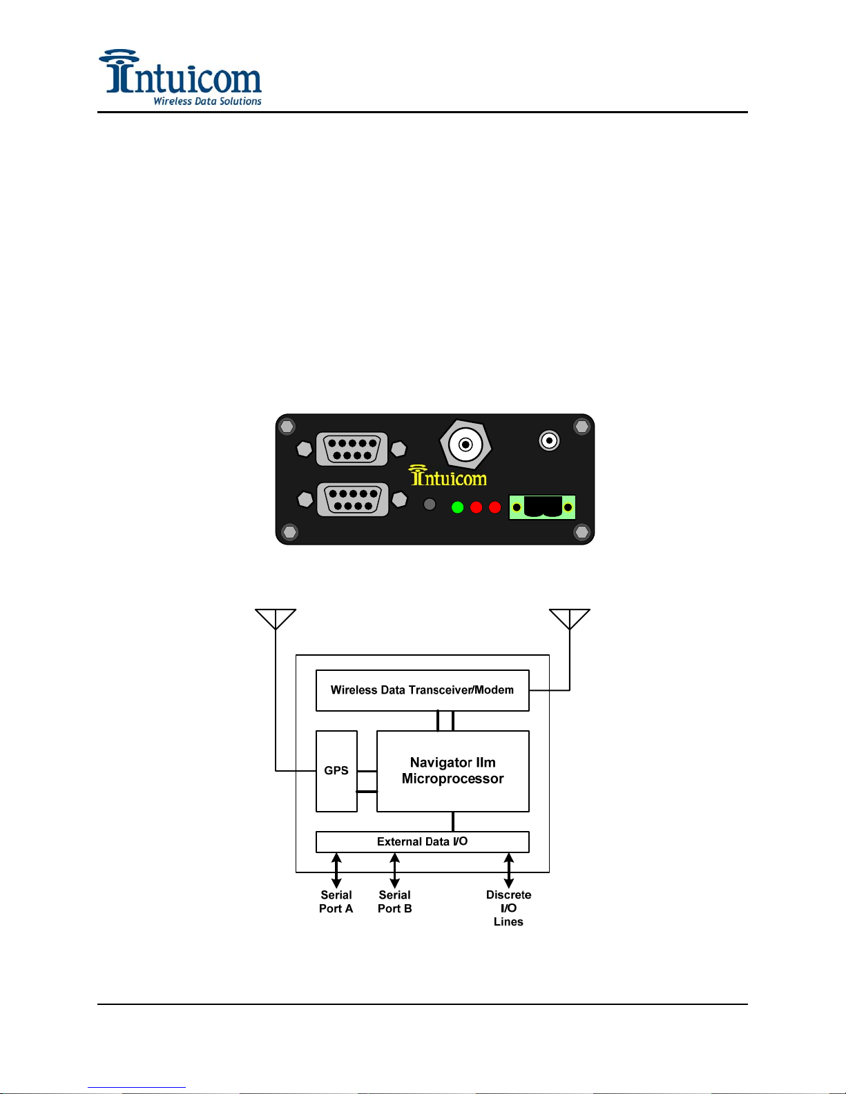
PORT A
PORT B
GPS
NAVIGATOR IIm
RADIO
SETUP
CD TX CTS
- +
Figure 1-1: Intuicom Navigator IIm Front Panel
Revision 1.0a 1 © 2006 Intuicom, Inc.
Figure 1-2: Navigator IIm Block Diagram

Section 1: Overview
1.2 Features and Benefits
• Choice of wireless bands. Intuicom Navigator IIm wireless data transceivers operate
in the license-free 900 Mhz ISM and 1.3 Ghz Military bands.
• Exceptional wireless performance, range and bandwidth.
• Connectivity for up to two external RS232 devices supporting interface baud rates
from 1200 to 115,200 baud.
• Optional integrated GPS receiver for location-based applications. GPS PPS signal
optionally available on Pin 1 of all ports.
• Discrete inputs and outputs for remote sensing and control (up to two inputs and two
outputs with RS232 signal levels).
• Highly flexible and configurable features including: data buffering, I/O routing, data
bursting (Intuicom Adaptive Multipoint), data port prioritization, and remote
diagnostics and configuration.
• Easy integration for remote devices with third party applications using Intuicom Nav-
Link server software and standard IP sockets. Bi-directional wireless communication
with remote serial devices attached to Navigator IIm units is made available on
dedicated IP sockets at a central location.
• Ability to operate in different modes (roles) in a network including slave,
slave/repeater, repeater, or master. Additionally DIRECT mode allows for two
Navigator IIms (or a Navigator II and a Navigator IIm) to operate as peers and create
a two port serial mux with the ability to receive the remote unit’s GPS data stream.
• Compact and ruggedized enclosure offering easy portability and mounting.
• Ability to operate using different wireless (over the air) protocols to tailor
performance to suit your specific application.
• Compatible with Intuicom Navigator II units and network – Navigator II and IIm
units can be mixed in the same network.
Revision 1.0a 2 © 2006 Intuicom, Inc.

Section 1: Overview
1.3 Common Applications
The Intuicom Navigator IIm can provide the key communications component to a wide
variety of customer applications including:
• Automatic Vehicle Location (AVL) and Messaging – Real-time location
information from vehicles as well as bi-directional messaging to mobile data
terminals.
• Seismic monitoring – Simultaneously returning real-time data from multiple
seismometers in the field.
• Weather network data collection – Returning real-time weather data from multiple
weather stations and data collectors in the field.
• Structural monitoring – Returning strain gauge and GPS data from structures such
as bridges, dams and buildings.
• Subsidence monitoring – Streaming GPS data in real time to monitor the ground
motion of a given geographic area.
• Marine towed buoy array – Buoy to ship communications returning GPS or other
sensor information.
• Device remote control – Remote control of power switching as well as remote state
(discrete) monitoring.
• SCADA – Wireless communication with remotely located MTUs.
• Wireless Serial Multiplexing – Using a single radio link to create multiple,
multiplexed serial-to-serial links.
Revision 1.0a 3 © 2006 Intuicom, Inc.

Section 1: Overview
1.4 Example Network Architecture
Figure 1-3 depicts one example of an Intuicom Navigator IIm network. In this application
three Navigator IIm units are operating as slaves, each with two attached serial devices. An
Intuicom Communicator II is operating as a repeater, and another Communicator II is
operating as the network Master transceiver. Intuicom Nav-Link server software is installed
on a PC attached to the Master transceiver and acts as the gateway between IP sockets and
individual remote serial ports.
Note: While Navigator IIm units can play any role in a Navigator IIm based wireless
network, Intuicom Communicator II basic transceivers can only operate as repeaters or as
the Master. Often times it is easier to have a single model of unit that can play any role in a
network and thus be a potential spare for any network role.
IP Network
Communications with remote serial ports made
available via TCP sockets (example):
10001 <-> Serial Device A
10002 <-> Serial Device B
TCP/IP
PC running
Intuicom Nav-Link
Software
RS232
Serial
Wireless
10003 <-> GPS #1
10011 <-> Serial Device C
10012 <-> Serial Device D
10013 <-> GPS #2
10021 <-> Serial Device E
10022 <-> Serial Device F
10023 <-> GPS #3
11000 --> GPS Messages from Units #1, #2, #3...
Communicator II
Master
Communicator II
Repeater
Intuicom
Wireless
Network
Solution
GPS GPS
Navigator IIm
Serial
Serial
Device A
Slave #1
Serial
Device B
Figure 1-3: Example Intuicom Navigator IIm Network
Revision 1.0a 4 © 2006 Intuicom, Inc.
Serial
Device C
Serial
Device D
Navigator IIm
Slave #2
Serial
Device E
GPS
Navigator IIm
Slave #3
Serial
Device F

Section 2: Configuration
2 Configuration
The Intuicom Navigator IIm is highly flexible but must be configured for your application before
use. Because the Navigator IIm can be configured for different roles in a wireless network, this
section covers all configuration options in detail and highlights key configuration steps for
specific network roles.
The Navigator IIm can operate in any of the following roles:
• As the Network Master – There must be one and only one Master transceiver in an
Intuicom wireless network. The Network Master, along with Intuicom Nav-Link
gateway software controls the wireless network and serves as the central gateway
between the wired and wireless. When the Navigator IIm is operating as the Network
master, Port A is dedicated for wireless diagnostics, Port B is dedicated for data.. An
Intuicom Communicator II transceiver can also serve the role of the Network Master.
• As a Network Slave – A Network Slave is the most common role for a Navigator IIm.
When operating as a Network Slave, the Navigator IIm can transfer data to and from
devices attached to its serial port as well as to and from its integrated GPS receiver.
• As a Network Repeater – When operating as a Network Repeater, the Navigator IIm is
only utilizing its integrated wireless data transceiver to repeat signals from other
slaves/repeaters/master, etc. An Intuicom Communicator II transceiver can also serve the
role a Network Repeater.
• As a Network Slave/Repeater – A Navigator IIm has the ability to operate as a Network
Slave and a Network Repeater simultaneously – both transferring data to and from locally
attached serial devices as well as repeating signals for other units in a given network.
• In Direct Mode – Direct mode is a special mode allowing two Navigator IIm transceivers
to communicate as peers, essentially creating a multiplexed wireless serial link mapping
Ports A and B of one of the Navigators to Ports A and B of the other. In addition, the
state of the input discretes can be reflected via the discrete outputs of the other unit.
Commonly a network consists of one Network Master and many Network Slave Navigator IIm
transceivers.
Revision 1.0a 5 © 2006 Intuicom, Inc.

Section 2: Configuration
2.1 Accessing the Navigator IIm Setup Menu
The Navigator IIm is configured via a serial connection using a terminal emulation program
such as Windows HyperTerminal or Symantec ProComm. Interacting with the Setup menu
is not platform specific; a terminal emulator on Unix/Linux, PalmOS, Pocket PC, etc. have
been tested and work. Configure the terminal emulation application for:
Parameter Setting
Baud Rate 19200
Data Bits 8
Parity None
Stop Bits 1
Flow control None
Table 2-1: Serial Settings to Access Setup Menu
The Navigator IIm Setup Menu is accessed by connecting a straight through serial cable
(non-null) between the PC and Port B then pressing the setup button on the front panel until
the menu appears as shown in Figure 2-2. All three status LEDs will turn green once the
setup menu has been activated.
PORT A
GPS RADIO
PORT B
NAVIGATOR IIm
Port B
SETUP
CD TX CTS
Setup
Button
- +
Figure 2-1: Setup Button and Setup Serial Port
To exit the Navigator IIm Setup Menu, press the ESC key (send and ESC sequence). Pressing
the ESC key will always exit the current menu and return to the previous menu. It is
recommended that when configuration is complete the ESC key be pressed a number of extra
times to ensure that Setup Mode is fully exited. The unit returns to Run Mode when not in Setup
Mode.
Revision 1.0a 6 © 2006 Intuicom, Inc.

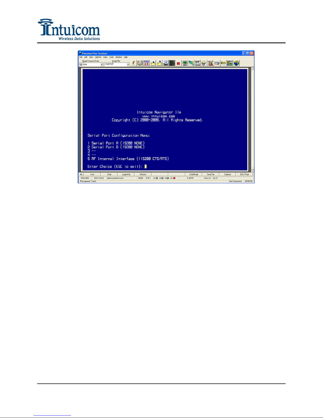
Section 2: Configuration
Figure 2-2: Navigator IIm Main Setup Menu
2.2 Serial Port Configuration
Option (1) from the Main Menu displays the Serial Port/Interface Configuration Menu shown
in Figure 2-3. From this menu, select the interface to configure. Serial Ports A and B are
available on the front panel of the unit. The default baud rate for Ports A and B is 19200
without flow control. Configure the baud rate for Ports A and B necessary to interface with
external equipment
Revision 1.0a 7 © 2006 Intuicom, Inc.
Section 2: Configuration
Figure 2-3: Serial Port Configuration Menu
Options (3) and (4) are reserved for different hardware version.
Option (5) refers to the baud rate between the Navigator IIm Microprocessor and the
integrated Wireless Data Transceiver. The default baud rate for this interface is 115,200 bps
with hardware flow control disabled. This baud rate must match the configured baud rate of
the internal Wireless Data Transceiver (see Section 2.4.2). This baud rate never be changed,
hardware flow control is automatically disabled when operating in Adaptive Multipoint
Mode (see Section 2.5.3).
Figure 2-4 shows the configuration menu for an individual serial port. The current
configuration is shown at the top of the menu with options below for changing baud rate and
flow control.
Revision 1.0a 8 © 2006 Intuicom, Inc.
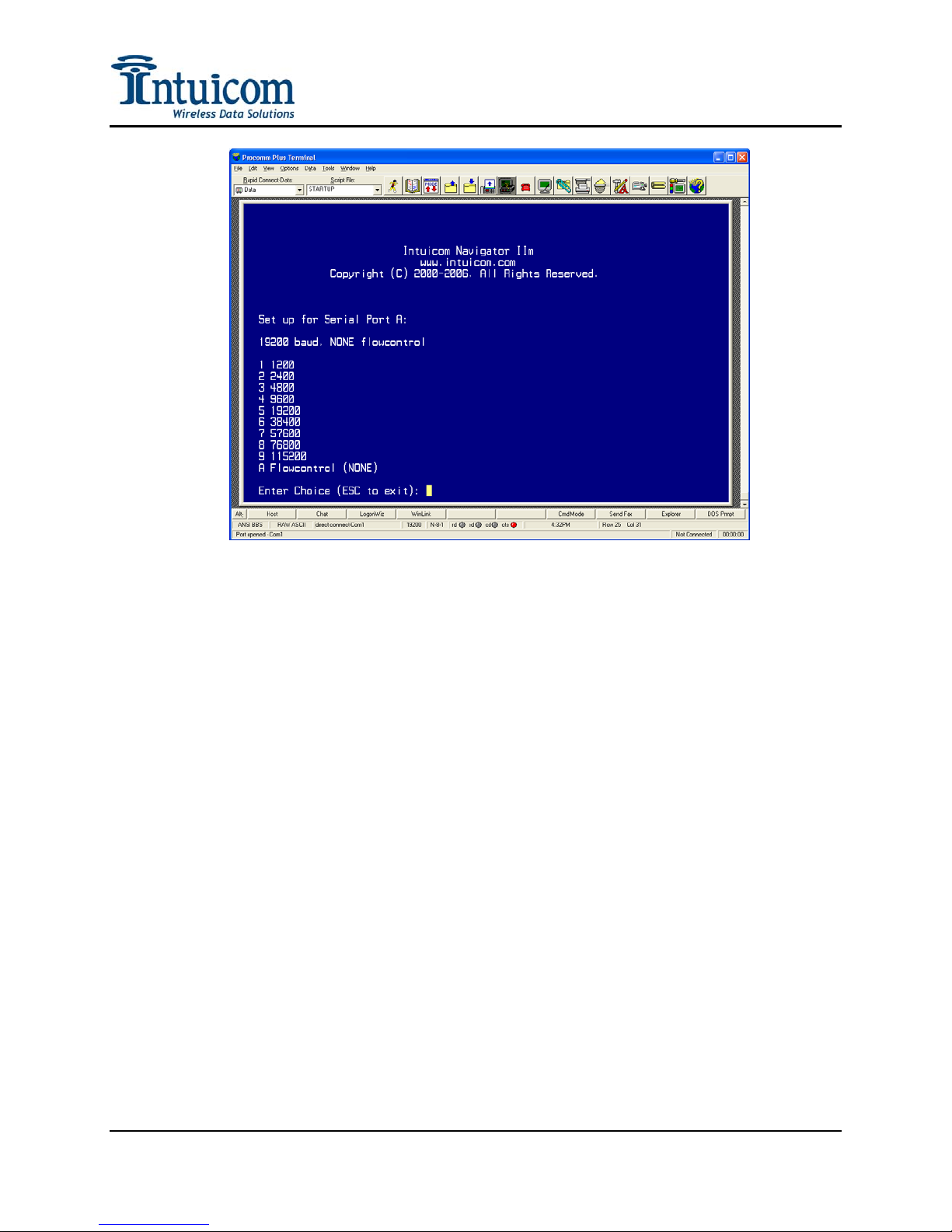
Section 2: Configuration
Figure 2-4: Serial Port A Configuration Menu
Revision 1.0a 9 © 2006 Intuicom, Inc.
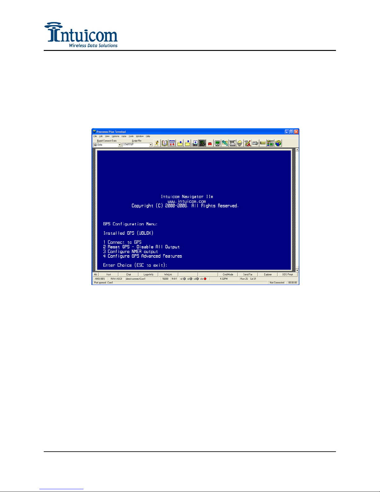
Section 2: Configuration
2.3 GPS Configuration
Select Main Menu Option (2) to configure the embedded GPS receiver. The GPS receiver
can be configured to output different NMEA data strings copies of which can be routed to the
local serial ports or be transmitted wirelessly (see Section 2.5.2). GPS output rates can be
configured at regular intervals or output can be trigged by moving a specified distance.
Figure 2-5: GPS Configuration Menu
2.3.1 Connect To GPS
This option connects the terminal session directly to the embedded GPS allowing the user
to directly see the GPS output. This option is useful when it is necessary to issue specific
configuration commands to the GPS that are not provided in the setup menu and to verify
correct GPS operation.
2.3.2 Reset GPS – Disable All Output
Select this option to disable all NMEA output from the GPS receiver.
2.3.3 Configure NMEA Output
This option allows the user to configure the NMEA output of the embedded GPS
receiver. A menu listing the available NMEA strings is shown. When a string selected
the user is prompted for an update rate in seconds. If the string number is selected again,
Revision 1.0a 10 © 2006 Intuicom, Inc.
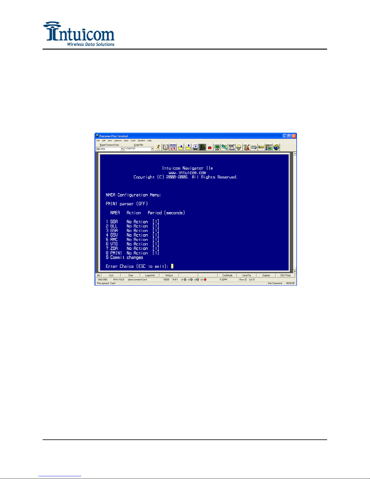
Section 2: Configuration
that string will be turned off, and if that string is selected again, no action will be taken
regarding that NMEA string when the configuration is committed to the GPS. Configure
any number and combination of strings and then select menu option (9) to commit the
configuration changes to the GPS receiver.
Note that the Period refers to the update rate for the selected NMEA string in seconds, i.e.
a setting of 5 would instruct the GPS receiver to output that string every 5 seconds. Not
all periods are supported.
Figure 2-6: GPS NMEA Configuration Menu
The $PMIN1 is a proprietary Intuicom NMEA string that combines the unique data from
the $GPRMC and $GPGGA messages into a single string to save bandwidth by
eliminating redundant data. The $PMIN1 string has the following format:
Revision 1.0a 11 © 2006 Intuicom, Inc.

Section 2: Configuration
$PMIN1,9069800,231524.00,4001.1856,N,10512.9904,W,0.1,164.2,1604.1,170602,2,0*03
| | | | | | | | | | | |
| | | | | | | | | | | PANIC
| | | | | | | | | | DGPS/SBAS
| | | | | | | | | DDMMYY
| | | | | | | | Altitude(m)
| | | | | | | Heading(degrees)
| | | | | | Speed(knots)
| | | | | E/W – East or West
| | | | Longitude
| | | N/S – North or South
| | Latitude
| hhmmss.ss
Unit ID
Figure 2-7: $PMIN1 NMEA String Data Format
$PMIN1,9253504,181319.000,4001.1862,N,10512.9993,W,0.00,19.59,1600.5,281106,2,0*00
$PMIN1,9253504,181320.000,4001.1862,N,10512.9993,W,0.01,19.59,1600.5,281106,2,0*0B
$PMIN1,9253504,181321.000,4001.1862,N,10512.9993,W,0.01,19.59,1600.5,281106,2,0*0A
$PMIN1,9253504,181322.000,4001.1862,N,10512.9993,W,0.00,19.59,1600.5,281106,2,0*08
$PMIN1,9253504,181323.000,4001.1862,N,10512.9993,W,0.01,19.59,1600.5,281106,2,0*08
$PMIN1,9253504,181324.000,4001.1863,N,10512.9993,W,0.00,19.59,1600.4,281106,2,0*0E
$PMIN1,9253504,181325.000,4001.1863,N,10512.9993,W,0.01,19.59,1600.4,281106,2,0*0E
$PMIN1,9253504,181326.000,4001.1863,N,10512.9993,W,0.01,19.59,1600.4,281106,2,0*0D
$PMIN1,9253504,181327.000,4001.1863,N,10512.9994,W,0.01,19.59,1600.4,281106,2,0*0B
$PMIN1,9253504,181328.000,4001.1863,N,10512.9994,W,0.01,19.59,1600.4,281106,2,0*04
$PMIN1,9253504,181329.000,4001.1863,N,10512.9994,W,0.01,19.59,1600.4,281106,2,0*05
Figure 2-8: Example $PMIN1 GPS Messages
Revision 1.0a 12 © 2006 Intuicom, Inc.
 Loading...