

Intuicom RTK Bridge-X, Ag Leader GPS 2500 Installation Manual

Installation Guide
RTK Bridge® -X
Integration with:
Ag Leader® GPS 2500®
4900 Nautilus Ct. Ste. 100
Boulder, CO 80301
(303) 449-4330
www.intuicom.com
Intuicom, Inc.

This Document is for internal use by Intuicom Employees or by Resellers and Distributors who
are authorized and/or licensed to install Intuicom products. No part of this document may be
reproduced or transmitted in any form or by any means, electronic or mechanical, or for any
purpose without the express written permission of Intuicom Inc.
© 2000-2014 Intuicom Incorporated. All rights reserved.
Intuicom reserves the right to make changes to this document without notice. Unless otherwise
agreed to in writing, Intuicom assumes no responsibility or liability for the use of this document
or for the infringement of any copyright or other proprietary right and Intuicom shall deem
nothing contained in this document a warranty or guarantee.
Intuicom is a registered trademark of Intuicom, Inc.
Other product names mentioned in this guide may be copyrights, trademarks, or registered
trademarks of their respective companies and are hereby acknowledged.
Version 1.0 1 Intuicom, Inc.

Section 1: Installation Requirements
Overview
The Ag Leader GPS 2500 smart antenna is typically configured to accept CMR or RTCM format
RTK corrections from an Intuicom RTK Bridge®-X which in turn has been configured to
connect to a GPS/GNSS reference network. The intended audience for this document is a dealer
or integrator familiar with the GPS 2500 as well as general familiarity with the Intuicom RTK
Bridge–X. The Intuicom RTK Bridge–X User Guide covers the steps necessary for its
configuration.
1 Requirements for Installation
1.1 Required Information
In order to operate an Intuicom RTK Bridge–X, you are required to have the necessary
information to access and log in to the Real-Time Network. This information is entered
into the RTK Bridge–X and stored in a profile. More details on setting up an RTK
Bridge–X is available in the RTK Bridge-X manual.
• IP address,
• TCP port,
• NTRIP mountpoint name,
• username and password for access to the real-time GPS/GNSS network
1.2 Required Equipment
1.2.1 Intuicom Equipment and Accessories
1. Intuicom RTK Bridge–X with activated data provider account (Verizon, AT&T, etc…)
2. Intuicom RTK Bridge–X Serial DB-9 data/power cable:
[P/N: XRTKPWDT-EZ]
3. Serial Null-Modem Adapter (Male-Male)
4. Intuicom RTK Bridge–X Cellular/GPS antenna/cable:
[P/N: FIP4-MMDM-MM (magnetic mount)]
1.2.2 Other Equipment and Accessories
1. Ag Leader Integra™ or Versa™ monitor for configuration
2. Ag Leader GPS 2500 with RTK unlock
3. GPS 2500 display cable with Port B available
Version 1.0 2 Intuicom, Inc.
Section 2: Installation Instructions
2 Installation Instructions
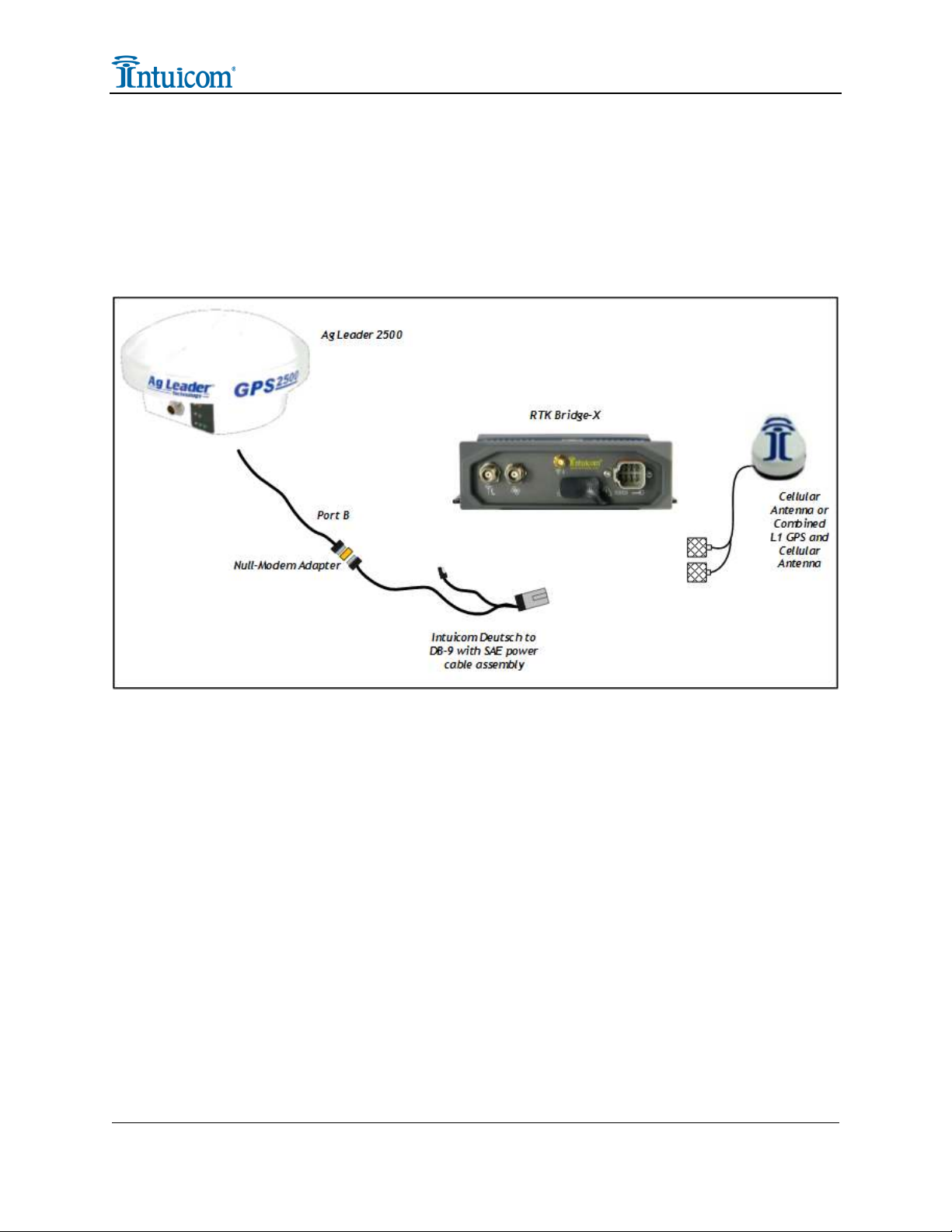
Below is the Installation Diagram for the recommended installation of the Intuicom RTK
Bridge–X utilizing the equipment noted above.
Diagram 1
2.1 Configuration
• Configure the Intuicom RTK Bridge–X to connect to GPS/GNSS Reference network
and obtain CMR or RTCM correction data stream from an appropriate single
reference station, such as a VRS.
• Configure the resulting RTK correction data to be output at a known baud rate (a
baud rate of 38400 is recommended).
• Confirm GPS and cellular antenna (typically a combined antenna with two coaxial
cables with TNC connectors) are connected and placed where they have good sky
view and good cellular signal.
• Using the Intuicom RTK Bridge-X to GPS 2500 data/power cable and null-modem
adapter, connect the RTK Bridge-X data port to Serial 2 (Port B) on the GPS 2500.
Version 1.0 3 Intuicom, Inc.
 Loading...