

Page 1
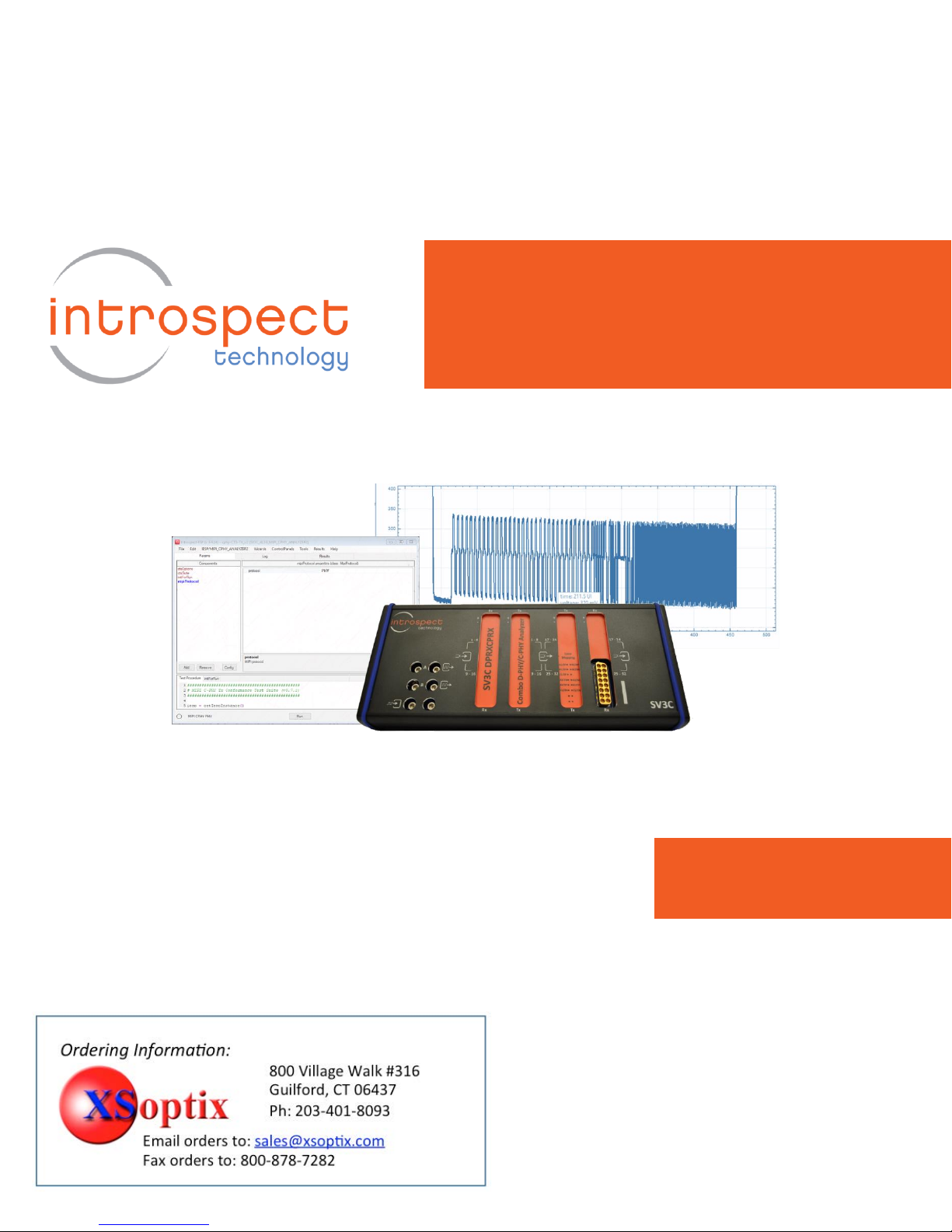
MIPI C-PHY Transmitter
Conformance Test Suite
User Guide
Page 2

Table of Contents
2
Table of Contents
Table of Contents .......................................................................................................................................... 2
List of Figures ................................................................................................................................................ 3
Introduction .................................................................................................................................................. 4
Features .................................................................................................................................................... 4
Hardware Setup and Global Method of Implementation ............................................................................. 5
CTS Application User Interface ..................................................................................................................... 9
Component Classes Visible to the User .................................................................................................... 9
CTS Options Component ....................................................................................................................... 9
Test Case Suite .................................................................................................................................... 10
User-Editable Initialization Function ................................................................................................... 10
Selecting the General Options for the Test............................................................................................. 10
Identifying Which Tests to Execute ......................................................................................................... 11
Confirming DUT Connections .................................................................................................................. 12
Entering Custom Code for Initializing the DUT ................................................................................... 13
Getting More Help ...................................................................................................................................... 14
Page 3

Table of Contents
3
List of Figures
Figure 1 Overall hardware setup for C-PHY Transmitter CTS testing. ........................................................ 5
Figure 2 Overall Method of Implementation involves performing waveform captures and extracting
measurements. Illustration is shown for CTS Test #1.2.2. ............................................................................ 6
Figure 3 Illustration of single-ended measurements. ................................................................................ 7
Figure 4 Hardware setup with attenuators in the signal path. .................................................................. 8
Figure 5 Illustration of the C-PHY Transmitter CTS Test Procedure when opened in IntrospectESP
software. ....................................................................................................................................................... 9
Figure 6 High-level automation options are configured using the ctsOptions data record. ................... 11
Figure 7 Illustration of the Test Case Suite GUI with a listing of all available tests. ................................ 11
Figure 8 Alternative graphical views of the Test Case Suite Window. ..................................................... 12
Figure 9 Illustration of the pop-up dialogs with connection instructions. ............................................... 12
Figure 10 User-editable code area for automatically initializing the test flow or the DUT. .................... 13
Page 4

C-PHY Transmitter CTS User Guide
4
Introduction
The Introspect C-PHY Transmitter CTS Application is a Test Procedure that
executes within the IntrospectESP software environment and that enables
automated testing of C-PHY transmitters using the Introspect SV3C CPRX 4Lane MIPI C-PHY Analyzer. The Test Procedure provides a fast and easy way to
validate and debug C-PHY links as well as execute automated C-PHY electrical
checklists based on the MIPI Alliance Conformance Test Suite.
The Introspect C-PHY Transmitter CTS Application enhances your productivity
and saves valuable time by allowing you to focus on the device under test (DUT)
specific steps of transmitter testing without worrying about test system
programming. It provides an easy to use interface for selecting and sequencing
tests and gives you visibility into the code structure and execution flows.
The Application also includes report generation features and custom code
sections that allow you to achieve true test automation – through a true
software handshake. Specifically, the custom code sections are compatible with
executing external scripts for controlling a device or for accessing your
proprietary .NET DLL for DUT control.
Features
The Introspect C-PHY Transmitter CTS Application offers
• MIPI specification coverage for C-PHY v1.0, v1.1, and beyond
• Configurable lane count and data rate
• Configurable test pattern / packet construction including arbitrary video
frames
• User selection of tests based on the CTS test groups
• User-editable custom code for manipulating external components such
as power supplies, device handlers, or thermal units
• Report generation
• Enhanced debug modes
Page 5
C-PHY Transmitter CTS User Guide
5
Hardware Setup and Global Method of Implementation
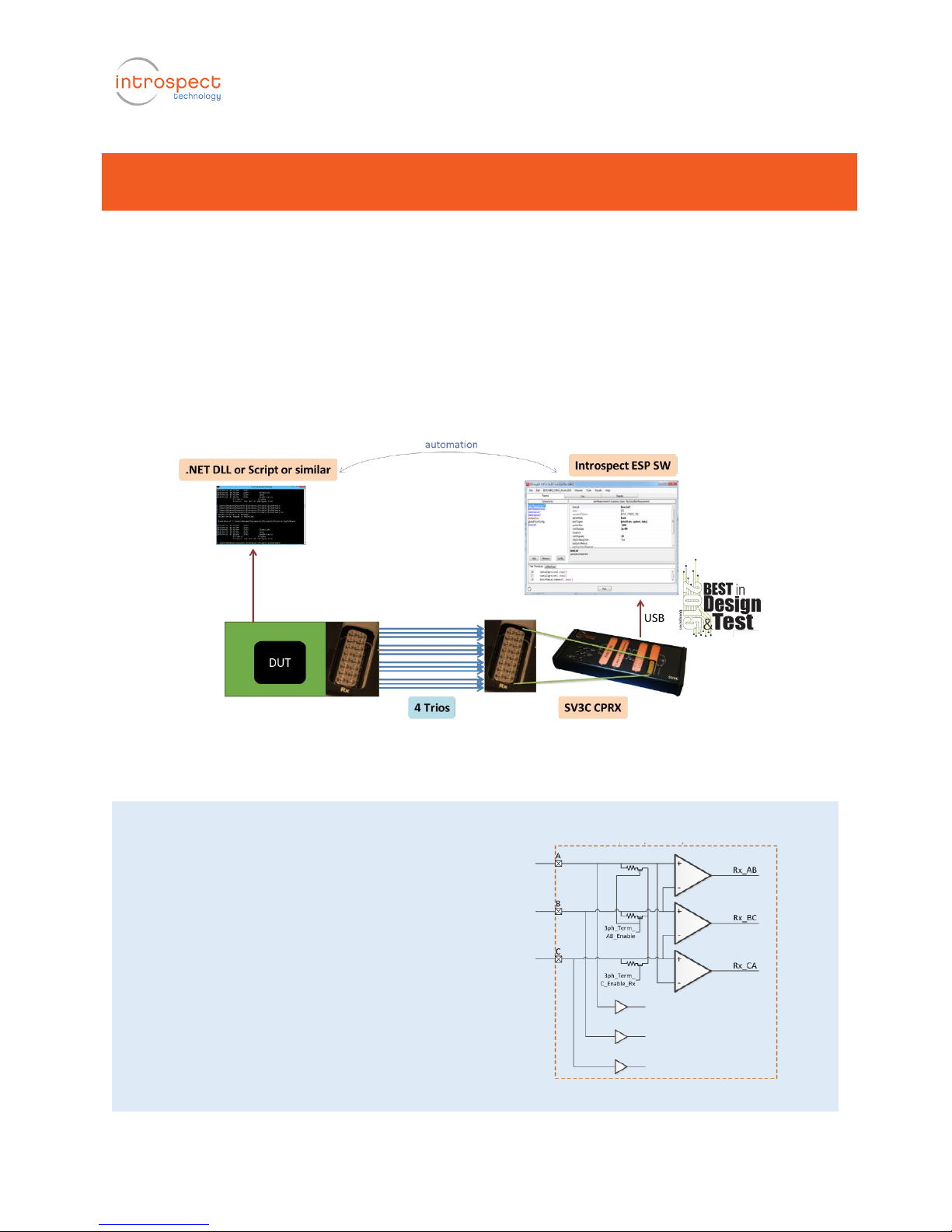
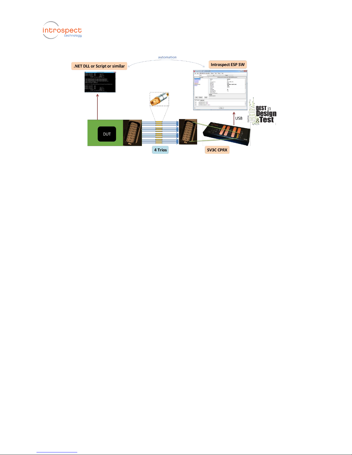
Figure 1 shows the hardware setup for transmitter tests in general. All lanes of
Introspect SV3C CPRX analyzer are connected directly to the Device under Test
(DUT) board. The SV3C CPRX is connected to the control Computer through a
USB cable and provided software drivers; and the DUT is connected to the
control Computer using its own mechanism (e.g. I2C to USB converter). In the
rest of this document, we assume that the DUT is connected to the same control
Computer as the SV3C CPRX, but this is generally not a requirement for the
Introspect CTS Application.
Figure 1 Overall hardware setup for C-PHY Transmitter CTS testing.
Noteworthy!
The SV3C MIPI C-PHY Analyzer contains built-in
dynamic termination circuitry as shown in the
figure on the right. Thus, unlike conventional
oscilloscopes or analyzers, it can be used to
directly connect to a MIPI device evaluation board
using coaxial cables, without requiring an external
Reference Termination Board (RTB) nor external
high-impedance probes!
This architecture results in faster setup time, lower
overall cost of test, and less potential for
connection issues.
Page 6
C-PHY Transmitter CTS User Guide
6
The Introspect ESP Software provides the main control for the SV3C CPRX, and
the features of the CTS Application will be described thoroughly in later sections
of this document. However, in this section, we describe the general scope of
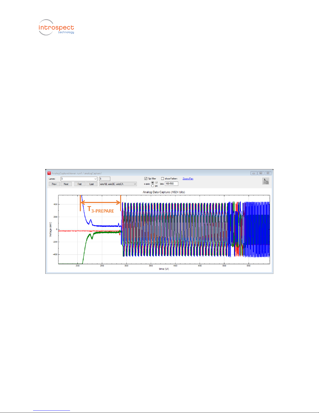
control within the CTS Application. Specifically, transmitter testing typically
requires setting up the DUT to generate repeating signals and measuring such
signals using the oscilloscope feature of the SV3C CPRX. Referring to Figure 2
which illustrates CTS Test #1.2.2, the DUT is configured to transmit a PRBS9
packet loop as defined in the MIPI C-PHY Specifications. Then, the SV3C CPRX is
commanded to perform a triggered oscilloscope capture and to extract the time
duration between the last LP transition and the first HS symbol transmission on
the line. In general, most CTS tests are performed on PRBS9 packet loops,
although this is customizable in the CTS Application.
Figure 2 Overall Method of Implementation involves performing waveform captures and extracting measurements. Illustration
is shown for CTS Test #1.2.2.
In the capture of Figure 2, differential waveforms on the AB, BC, and CA
amplifier signals were displayed because this was appropriate for the particular
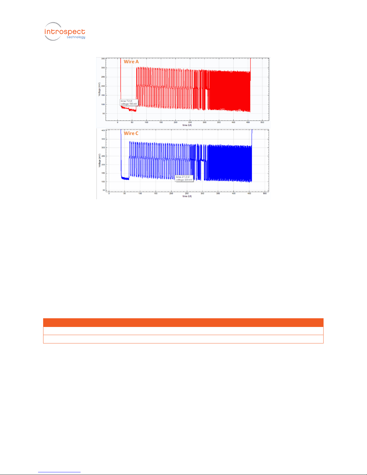
test. For other tests, it is important to measure the high-speed signals in singleended manner, and this is illustrated in Figure 3. The Introspect C-PHY CTS
Application automatically determines whether or not a test requires singleended measurement, and it automatically configures the SV3C CPRX to enable
such measurement.
Page 7
C-PHY Transmitter CTS User Guide
7
Figure 3 Illustration of single-ended measurements.
For some tests (e.g. Group 1) in the MIPI C-PHY CTS Specifications, the SV3C
CPRX is expected to measure large-magnitude LP signals at 1.2V. Since this
exceeds the linear range of the high-bandwidth input amplifiers on the
Analyzer, these tests require the inclusion of a signal attenuator in the
connection between the DUT and the Analyzer. An illustration of such
connection is shown in Figure 4, and a list of recommended attenuator
components is included in Table 1. During execution, each CTS Test instructs the
user to insert the appropriate attenuator into the DUT signal path.
Table 1 Recommended co-axial fixed attenuators for performing voltage measurements in the CTS
Parameter Under Test
Required Attenuation
Recommended Part Number
HS Signal Voltage
6 dB
Mini-Circuits VAT-6+
LP Signal Voltage
15 dB
Mini-Circuits VAT-15+
Page 8
C-PHY Transmitter CTS User Guide
8
Figure 4 Hardware setup with attenuators in the signal path.
Page 9

C-PHY Transmitter CTS User Guide
9
CTS Application User Interface
This section describes the components within the CTS Application. It then
proceeds with instructions on how to configure tests, execute them, and
customize their responses.
Component Classes Visible to the User
Figure 5 shows the Application window when it is first loaded into the
IntrospectESP software. As can be seen, it is populated with a group of
components that are highlighted, and these constitute the principal method for
configuring tests and automating them. In the following sections, each
component will be described briefly.
Figure 5 Illustration of the C-PHY Transmitter CTS Test Procedure when opened in IntrospectESP software.
CTS Options Component
This component defines general test options related to automation and report
generation. For example, it defines the behavior of the Application in case one
of the tests of the CTS fails. Based on the user requirement, the entire test
sequence can be aborted, or the test can be skipped and subsequent tests
executed. Similarly, this component is used to decide whether automated report
generation is required or not. Finally, this component is where DUT parameters
such as data rate and number of lanes are specified.
Page 10

C-PHY Transmitter CTS User Guide
10
Test Case Suite
The Test Case Suite is a powerful automation development tool within the
IntrospectESP software. It allows software developers to create unit test
functions and to handle their execution in a robust manner. The Test Case Suite
has been used in this Application to create Test Case code for each of the tests
in the MIPI C-PHY CTS Specifications.
Double-clicking on the Test Case Suite launches a simple GUI for selecting test,
debugging them, or executing the entire test flow.
User-Editable Initialization Function
This is a function tab (visible in the Test Procedure section of the GUI) that
allows you to enter custom code for initializing the test in general or for
initializing signal transmission from the DUT. In general, the CTS requires the
generation of repeating packet loops. But it is possible that some tests can be
customized in the following manners:
• Replacing the PRBS9 packet loop with an image pattern loop
• Replacing the PRBS9 packet loop with repeating LPDT transmissions
• Configuring the DUT to generate static LP111 or LP000 values
Selecting the General Options for the Test
Figure 6 shows the ctsOptions data record component, which is used to select
the options for the test. Typically, all defaults are valid. The parameter
descriptions include items such as:
• runNominalTest: this commands the CTS Application to execute a quick
pattern check on the device before any test is performed, thus verifying
that the hardware setup is valid
• stopAfterFirstFailure: set this parameter to True if you want the CTS
Application to abort after any of the tests fails
• reportGeneration: enables the creation of a CSV report of executed tests.
Generated reports are accessible in the Results tab of the GUI
Other options in this data record include features related to particular test
configurations. Context help is available for these and other options in the CTS
Application.
Page 11
C-PHY Transmitter CTS User Guide
11
Figure 6 High-level automation options are configured using the ctsOptions data record.
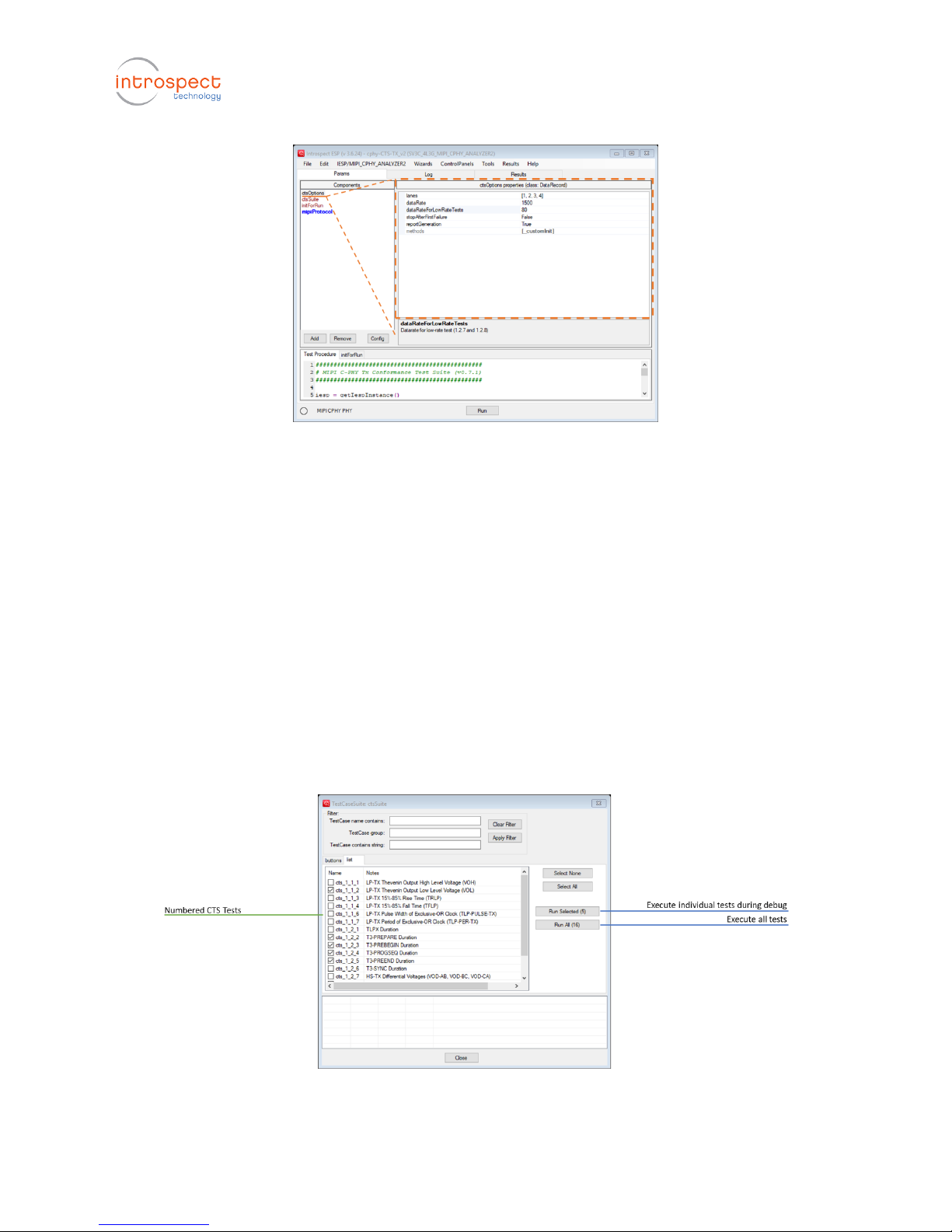
Identifying Which Tests to Execute
Once the general options are established, the next step is to select which CTS
tests to execute. This is done from within the Test Case Suite as shown in Figure
7. This Test Case Suite Window was launched by double-clicking on the ctsSuite
component from within the IntrospectESP software. The window displays the
available tests and allows for a very flexible execution environment for the user.
For example, the user can select to enable all test cases, disable all test cases, or
individually run each test case in isolation. What is important to note is that
each execution is capable of producing the appropriate results data
independent of other tests, and this represents tremendous flexibility during the
debug and validation phase of testing.
Figure 7 Illustration of the Test Case Suite GUI with a listing of all available tests.
Page 12

C-PHY Transmitter CTS User Guide
12
Figure 8 shows an alternative Graphical view of the Test Case Suite Window. This
view allows the user to highlight only a specific group of tests and to arbitrarily
click on them for execution. When a test is clicked (right hand side of the figure),
a context bubble appears indicating execution, and the main window of the
IntrospectESP Software displays the activity log as usual.
Figure 8 Alternative graphical views of the Test Case Suite Window.
Confirming DUT Connections
As was mentioned earlier, some tests require the insertion of attenuators in the
signal path. Determining such connection requirements happens dynamically
within the C-PHY CTS Application, and this is illustrated in Figure 9. When a test
case is selected, a pop-up window describing the required connections appears,
and the test is not executed until the connections have been made.
Figure 9 Illustration of the pop-up dialogs with connection instructions.
Page 13

C-PHY Transmitter CTS User Guide
13
Entering Custom Code for Initializing the DUT
The C-PHY Transmitter CTS Application includes a function tab with user visible
code in it. This function is executed at the beginning of the CTS, and it can be
used to send initialization commands to the DUT. An illustration of the function
tab with pre-populated code is shown in Figure 10. The illustrated code relates
to caching of results or measurement configurations, and it is intended to
demonstrate the flexibility of the tool. Indeed, any Python code or system-call
code to external software can be included in this function tab.
Figure 10 User-editable code area for automatically initializing the test flow or the DUT.
Page 14

C-PHY Transmitter CTS User Guide
14
Getting More Help
This document introduced the Introspect C-PHY Transmitter CTS Application at
a high level, and it provided a detailed description of its user interface. Various
other sources of information are available, and these include
• Online html help files from within the IntrospectESP software
• Context help provided with each of the components and each of the
parameters
• Introspect SV3C CPTX CPRX QuickStart (document number EN-G003E-E-
15279)
• Introspect SV3C CPRX Data Sheet (document number EN-D002E-E-
17339)
Page 15

Introspect Technology http://introspect.ca info@introspect.ca
Revision Number
History
Date
1.0
Initial document release
June 13, 2018
The information in this document is subject to change without notice and should not be construed as a
commitment by Introspect Technology. While reasonable precautions have been taken, Introspect
Technology assumes no responsibility for any errors that may appear in this document.
© Introspect Technology, 2018
Published on June 13, 2018
EN-G026E-E-18164
 Loading...