

Page 1

Intro 850
Intro 950
Instantaneous Electric Shower
Installation and User Instructions
This Step-by-Step guide should be given to the customer
IMPORTANT!
after installation and demonstration.
Page 2
CONTENTS 1. PACK CONTENTS
Intro 850
Intro 850
1. Pack Contents 3
2. Installation Check List 4
3. Important Safety Information 5
Installation
4. General Installation Layout Guide 7
5. Important Installation Information 8
6. Fixing the Shower to the Wall 8
7. Product Positioning Guide 9
8. Plumbing Connections 10
9. Electrical Connections 11
10. Fitting the Front Cover 12
11. Riser Rail Fitting Instructions 13
12. Commissioning the Shower 14
User Guide
13. Operating the Shower 15
14. How Your Shower Works 16
15. Routine Maintenance 16
16. Troubleshooting and FAQs 17
17. Troubleshooting Checklist for the Installer 18
18. Product Warranty 19
19. Service Policy 20
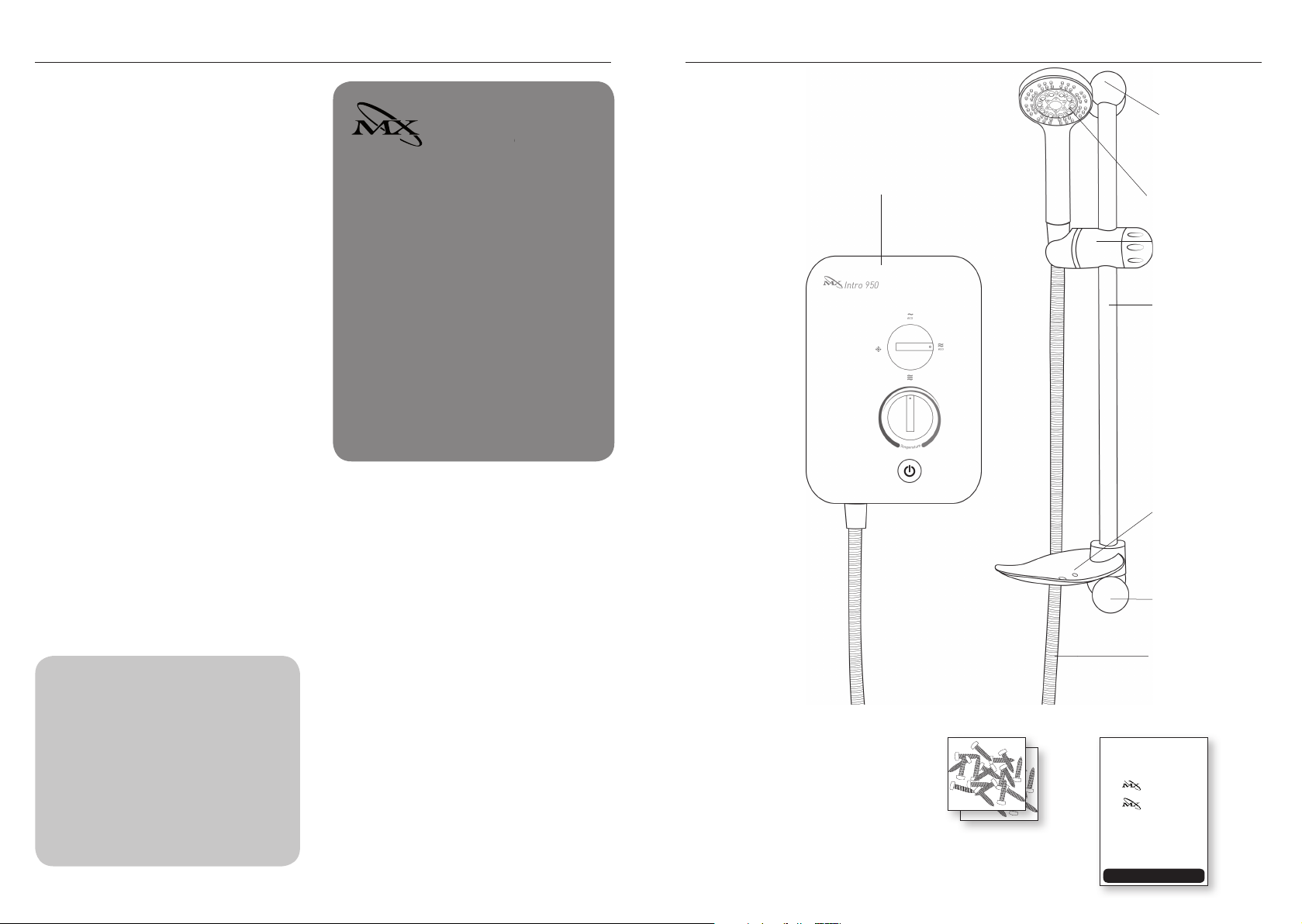
MX Intro 850 and 950 – a guide for installers
The compact MX Intro 850 (8.5 kW) and
950 (9.5 kW) shower models are designed for
quick installation. Both water and electrics enter
the shower unit from the right hand side of the
back plate with top bottom and rear options.
A removable corner section allows easy access
for the plumbing connection. The screw wall
mounting hole positions are visible when the front
cover is removed. The top two fixing holes are
vertical key hole slots and the bottom fixing hole is
a horizontal slot to allow for alignment.
The MX Intro 850 and 950 electric showers are
designed for Domestic and light commercial
applications.
• 1. Shower Unit
Please make sure ALL
components are included
before starting the
installation.
1. Shower Unit
2. Shower Handset
3. Riser Rail Tube
4. Riser Rail Brackets x2
These instructions contain
all the necessary fitting and
operating instructions for
your electric shower. Care
taken during the installation
will provide a long, trouble
free life from your shower.
2 3
5. Riser Rail Height Adjuster
6. Flexible Shower Hose
7. Soap Dish
8. Hose Retaining Ring
9. Screw Packs
10. Installation and User
Instructions plus
Guarantee Card
• 9. Screw Packs
• 4. Riser Rail Bracket
• 2. Shower Handset
• 5. Riser Rail
Height Adjuster
• 3. Riser Rail Tube
• 7. Soap Dish
• 4. Riser Rail Bracket
• 6. Flexible Shower Hose
• 10. Fitting Instructions
& Guarantee Card
Intro 950
Instantaneous Electric Shower
Installation Instructions
IMPORTANT!
This Step-by-Step guide should be given to the customer
after installation and demonstration.
Page 3
!
!
!
!
!
!
!!!
!
!
!!!
!
!
2. INSTALLATION CHECK LIST
3. PLEASE READ THIS IMPORTANT SAFETY INFORMATION
1. Check that the water supply will satisfy requirements .....................................
2. Check that water and cable entry points of the unit meet requirements ......
3. Check that the electric supply will satisfy requirements ..................................
4. Select a suitable position for the shower .............................................................
5. Plumbing installation ..............................................................................................
6. Electrical installation ...............................................................................................
7. Fit to the wall and connect the shower supplies ................................................
8. ONLY Commission the shower in the way described ......................................
9. Fitting the front cover and aligning the controls .................................................
10. Familiarise yourself with the user operating instructions ...............................
Products manufactured by the MX Group are safe and without risk provided
they are installed, used and maintained in good working order in accordance
Tick off as you complete
with our instructions and recommendations.
FOR THE USER:
WARNING: DO NOT operate shower if frozen, or suspected of being frozen.
It must thaw out before using.
DO NOT operate the unit if the showerhead or spray hose becomes
damaged.
DO NOT restrict flow out of shower by placing showerhead in direct contact
with your body or ther solid object.
WARNING: the outlet of the shower acts as a vent and must not be
connected to anything other than the flexible shower hose and handset
supplied or approved by the manufacturer.
DO NOT operate the shower if water ceases to flow during use or if water
has entered inside the unit because of an incorrectly fitted cover.
DO NOT place items such as soap, shampoo or other such bottles on top of
the unit as liquid could leak through the joint between the cover and back
plate and damage the sealing rubber.
The shower spray head MUST be cleaned regularly to remove scale and
debris. The frequency of the cleaning will vary according to the local water
quality. If the water outlet temperature becomes hot and you are unable to
obtain cooler water, immediately check the shower handset for blockage.
See section 15 for cleaning instructions.
IMPORTANT: This appliance is not intended for use by persons (including
children) with reduced physical, sensory or mental capabilities, or lack of
experience and knowledge, unless they have been given supervision or
instruction concerning use of the appliance by a person responsible for
their safety. Children should be supervised to ensure they do not play with
the appliance.
4 5
Page 4
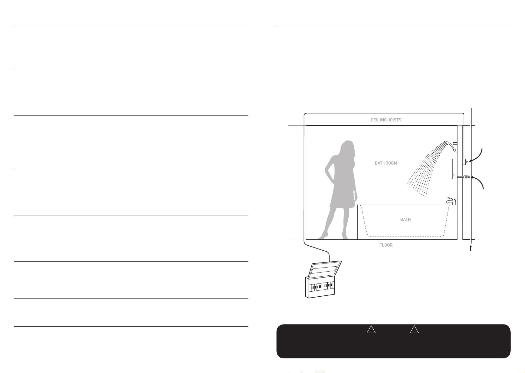
PLEASE READ THIS IMPORTANT SAFETY INFORMATION (CONT.) 4. GENERAL INSTALLATION LAYOUT GUIDE
BATH
BATHROOM
FLOOR
CEILING JOISTS
!!!
!
FOR THE INSTALLER:
MAINS SERVICE CONNECTIONS: The shower unit is supplied for right hand
mains water and electrical connection.
IMPORTANT: To comply with water regulations, building regulations or any specific
local water company regulations and in accordance with BS EN 806 a double check
valve should be fitted where it is possible that the shower head may come into
contact with used water, for example in the bath or a shower tray.
IMPORTANT: Check that there are no hidden cables or pipes before drilling
holes for the wall plugs. Choose a flat piece of wall to avoid the possibility of
distorting the back plate and making the front cover a poor fit. Exercise great care
when using power tools near water. The use of a residual current device (RDC) is
recommended.
IMPORTANT: Before connecting the water supply to the shower
unit the water supply pipe should be flushed out to remove all debris. After
flushing the pipe work make the connection to shower inlet and ensure the
shower is positioned squarely on the wall and all fixing screws are tightened.
Plan your installation carefully. Check on the nearest
and most accessible rising main water supply, this
may be beneath the bath or in the loft, where it feeds
the water storage tank. Use only the cold rising
water main.
Avoid connecting the shower unit if possible where
it will be affected by water drawn off by another
appliance.
For example from the mains feed to the toilet as this
may cause a drop in pressure to a level that is too low
for the shower unit to work correctly.
A WRAS (Water Regulations Advice Scheme) listed
isolating valve must be fitted between the rising main
and the unit to comply with water regulations and to
allow for routine maintenance and servicing.
DOUBLE POLE
HEATER SWITCH
WALL MOUNTED
IN ACCORDANCE
WITH LOCAL
AUTHORITY
REGULATIONS
SHOWER
UNIT
ISOLATING
STOP TAP
IT IS VERY IMPORTANT to ensure that the terminal block screws are FULLY
tightened and that no cable insulation is trapped under the screws. The earth
continuity conductor of the electrical installation must be effectively bonded to
earth on the fuse board.
SEPARATE PERMANENTLY
CONNECTED SUPPLY
FROM CONSUMER UNIT
COLD WATER
MAINS SUPPLY
IMPORTANT: Ensure that the flow / temperature control knob is turned to FULL
flow and the commissioning instructions are followed before switching the unit on.
This will make sure that the unit is full of water when first activated.
IMPORTANT: The shower unit MUST be full of water before the heat settings
are used.
IMPORTANT
This appliance is not intended for use by persons (Including children) with reduced physical, sensory or
mental capabilities, or lack of experience and knowledge, unless they have been given supervision or
instruction concerning use of the appliance by a person responsible for their safety. Children should be
6 7
supervised to ensure that they do not play with the appliance.
Page 5

5. IMPORTANT INSTALLATION INFORMATION
7. PRODUCT POSITIONING GUIDE
n Shower installation must be carried out by a
suitably qualified person and be in accordance with
BS 7671 (IEE wiring regulations) building regulations,
water regulations and or any specific local water
n The shower unit must not be fitted where it may
be exposed to frost, for example in an outdoor area.
The shower must not be used if suspected of being
frozen. Frost damage is not covered by the guarantee.
company regulations in force and should be in
accordance with BS EN 806.
n Plumbers jointing compound must not be used.
In instances of difficult joints use P.T.F.E. Tape.
n This shower unit is designed to be connected to a
15mm cold water mains supply.
n To make sure the heating elements are activated
the shower must be connected to mains water supply
with a minimum running pressure of 100kPa (15lb/
The use of jointing compound will invalidate the
product guarantee.
n DO NOT solder fittings near the shower unit
as heat can travel along pipe work and damage
components.
sq in) – 1 Bar at a minimum flow rate of 8 litres per
minute. The maximum static pressure is 1000kPa
(150lb/sq in) 10 Bar.
n DO complete all plumbing connections before
making the electrical connections.
NOTE: For the Intro 950 9.5kW model, the minimum
running pressure must be obtained at 9 L/min.
6. FIXING THE SHOWER TO THE WALL
Position your shower on the wall so that it will NOT
be in the direct water spray from the shower handset
when fixed.
You may wish to consider mounting the unit so that
the shower handset could be used over a sink for
washing hair.
The shower unit should be positioned so that the
shower head cannot be immersed in the bath or
shower tray when hanging down. A shower hose
retainer is supplied with the accessories (see pages
3 and 9).
Remove the four front cover fixing screws and lift
the cover off complete with the control knobs and
start /stop push button.
Having decided on the water and cable entry points
and chosen a flat piece of wall, hold the shower
vertically against the wall and mark the top two
fixing holes.
Carefully drill the two holes as marked using a sharp
5.5mm masonry drill after first making certain there
are no pipes or wires behind the proposed holes.
Insert the wall plugs and screws provided leaving the
screw head proud by approximately 5mm. The shower
can now be hung on these screws.
Make sure that the shower is positioned vertically now
mark and drill the lower slotted fixing hole. Then fix
the shower to the wall. Do not fully tighten the screws
at this stage.
The shower back plate and removable corner
moulding have moulded knock out sections which
are clearly indicated to allow the chosen service entry
option to be removed prior to final fix.
Shower unit can be mounted
either side of riser rail
Intro 950
eco
eco
T
e
e
r
m
u
t
a
e
p
r
25mm minimum
Outline of bath or
shower tray
Height of
showerhead
and shower
to suit user’s
requirements
Soap dish
Hose retaining ring
Spillover level
Spillover level
8 9
Page 6

!!!
!
!!!
!
8. PLUMBING CONNECTIONS
!!!
!
9. ELECTRICAL CONNECTIONS
The shower back plate incorporates into the lower
right side a removable corner section to allow easy
access when deciding on and connecting to the water
mains supply.
Remove the bottom right hand side corner section
giving access to the water inlet spigot.
The shower unit is supplied for right hand installation.
IMPORTANT: Before connecting the mains water
supply to the shower flush out the pipe work to
remove all swarf and system debris. This is achieved
by connecting a hose to the pipe work and turning on
the mains water supply at the isolating stop tap long
enough to clear the debris to waste.
Turn off the mains water supply at the isolating
stop tap.
Check that the inline filter is fitted to the inlet pipe.
Having decided on the direction of the water inlet
supply: Top (falling) Bottom (rising) or rear inlet it
is necessary to remove the appropriate knock out
(thinned out plastic) cross section from the back
plate before commencing with the installation. The
connection to the unit is made using a 15mm copper,
stainless or plastic pipe with a 15mm compression
elbow or 15mm push fit elbow.
IMPORTANT: Do not use excessive force when
making the connection to the unit.
Now tighten the back plate fixing screws so the
unit is firmly fixed to the wall.
If rear entry pipe work is used we recommend the use
of a suitable sealant to seal around the incoming pipe
NOTE!
PLUMBING THE SHOWER
UNIT MUST PRECEDE WIRING!
IMPORTANT
To comply with water regulations, building regulations or any specific local water company regulations and
should be in accordance with BS EN 806. A double check valve must be fitted with all flexible
shower accessories where it is possible that the showerhead may come into contact with used water
work to prevent water entering the wall.
Turn on the mains water supply and check for leaks.
At this stage no water can flow through the unit.
IMPORTANT: Remember to replace the lower corner
section before refitting the front cover.
Top knock out section for
mains water and cable entry
Water inlet with
removable filter for
cleaning.
Bottom
knock out
section for
mains water
and cable
Removable cover plate for
bottom inlet, accessible once
the cover is removed. Simply
slide this back into place
before replacing the cover.
entry.
The electrical installation must be in accordance with
the current BS 7671 (I.E.E. wiring regulations) and
part P of the building and / or local regulations.
The shower unit is designed for a single phase 50 Hz
a.c. electrical supply.
ELECTRICAL SPECIFICATIONS
Nominal Power rating at 240V
8.5kW - (40A MCB rating)
9.5kW - (40A MCB rating)
IMPORTANT: The heating elements on the UK
models are manufactured to 240V specification and
will give a lower kW rating if the voltage supply is
below 240V.
The shower unit must be permanently connected
to the electrical supply, direct from the consumer
unit via a double pole linked switch with a minimum
contact gap of 3 mm. The switch must be readily
accessible and clearly identifiable and sited out of
reach of a person using the shower over a fixed
bath or shower tray, unless the switch is pull cord
operated. The wiring must be connected to the
switch without the use of a plug or socket outlet.
The supply cable size is determined by the kW rating
of the product (as detailed on the rating plate fixed
to the back plate) and the distance between the
shower and the consumer unit. The table below is
for guidance only but will help you choose the correct
cable for your installation. If you are in any doubt
consult an electrician.
KW
NOMINAL
RATING
AT 240V
7.5 31.25amps 40amps 40amps 29m 48m
8.0 33.33amps 40amps 40amps 27m 44m
8.5 35.41amps 40amps 40amps 23m 38m
9.5 39.58amps 40amps 40amps 21m 32m
10.5 43.75amps 45amps 45amps 18m 30m
Nominal Power rating at 230V
7.8kW - (40A MCB rating)
8.7kW - (40A MCB rating)
MINIMUM
RATING OF
ISOLATING
SWITCH
FUSE
RATING
MAX CABLE
RUN
6mm 10mm
The incoming cable should be hidden. Connect as
follows:
Earth cable to terminal marked
Neutral cable to terminal marked N
Live cable to terminal marked L
The outer sheath of the supply cable must be striped
back to a suitable length and the earth conductor
must have an earthing sleeve fitted.
Connect the cable to the terminal block. Ensure that
ALL the retaining screws are VERY tight and that NO
cable insulation is trapped under the screws. Loose
connections can result in cable overheating.
IMPORTANT: Failure to ensure that the retaining
screws are VERY tight could result in a failure of the
terminal block.
IMPORTANT: DO NOT switch on the electricity supply
until the shower cover has been fitted.
N
L
i.e. In the bath or shower tray.
IMPORTANT
IMPORTANT
Before turning on the water supply to the shower unit the water supply pipe should be flushed out to remove
debris. After flushing the pipework ensure that the shower unit is positioned squarely on the wall and tighten
the screws. Tighten all plumbing connections and check the pipework for leaks.
Ensure that the terminal block screws are fully tightened and that no cable insulation is trapped under
screws. Ensure the cable clamp is used to secure the cable. The earth continuity conductor of the electrical
installation must be effectively connected to all exposed metal parts of other appliances and services in the
room in which the shower unit is installed to confirm
10 11
Terminal
block
Page 7

ELECTRICAL CONNECTIONS (CONT.)
!!!
!
!
!
11. RISER RAIL FITTING INSTRUCTIONS
The diagram below shows a schematic wiring
diagram.
IMPORTANT: The use of connections within the unit
or other points in the shower circuit to supply power
to other equipment such as an extractor fan or pump
etc will invalidate the guarantee.
1. Thermal cut-out
2. Pressure switch
3. Heater body
3
2
1. Establish position for the riser rail, and mark
the wall for the lower mounting bracket. Make
allowances for the tallest person likely to use the
shower regularly.
2. Remove covers from the wall brackets.
3. Position the lower bracket and mark the wall forthe
screw fixing. Then drill and plug the wall and fix the
lower bracket without the rail location notch.
1
L
N
E
10. FITTING THE FRONT COVER
IMPORTANT: it is necessary to align the control
knobs on the cover with the opposite control spindles
mounted of the back plate before the front cover is
fitted.
First turn the power selector knob to the cold position.
Intro 950
Then turn the flow / temperature controlknob
anti-clock wise to the mechanical stop position
(maximum flow).
On the shower back plate make sure that the power
selector spindle key way is pointing down and the
temperature spline spindle is rotated fully anti-
clockwise until it reaches the mechanical stop.
The front cover can now be fitted carefully ensuring
the controls are aligned and secured with the four
fixing screws provided.
Following the installation of the riser rail (see section
11) attach the flexible hose to the shower outlet
positioned centrally on the back plate making sure
that you use the seal washer provided. The shower is
now ready for commissioning.
12 13
STOP
4. Fit the rail into the lower bracket. Place the
remaining bracket with the rail location notch
on top of the rail, making sure that the rail slot is
located into the notch. Ensure the hole position is
vertically aligned and mark the wall. Remove the
rail and bracket, then drill and plug the wall.
5. Slide the height adjuster onto the rail. Tighten to
the rail by turning the locking cap. Then fit the
soap dish, dampening the rail will make it easier to
slide on. Finally fit the hose retaining ring onto the
bottom of the rail below the soap dish.
6. Replace the rail assembly into the lower bracket.
Refit the top bracket, ensuring the slot in the rail is
located into the bracket notch and fix to the wall.
7. Slide covers onto both brackets.
8. Firmly attach flexible hose to showerhead making
sure sealing washer is in place after first passing
through the hose retaining ring.
NOTE: The adjustable height adjuster grips the conical
ends of the hose, not the handle of the showerhead.
CAUTION
Check there are no hidden cables or pipes before drilling holes for wall plugs.
Exercise great care when using power tools near water.
The use of a residual current device (RCD) is recommended.
TIPS
• A piece of insulating or masking tape applied
to the wall before marking out the fixing
holes will help stop the drill from wandering,
particularly on tiled surfaces.
• When working near a basin or bath, insert the
plug in the waste fitting so that small parts
cannot be lost.
• Take care not to drop accessories or tools into
basin or bath.
Page 8

12. COMMISSIONING THE SHOWER
!!!
!
!!!
!
13. OPERATING THE SHOWER
1. Make sure that the electricity supply has been
isolated at the double pole isolating switch.
2. Turn the top rotary power selector knob to the Cold
setting.
3. Turn the rotary flow / temperature control fully
anti-clockwise to the maximum flow position
(direction of blue graphic).
4. Ensure that the water supply is fully on at the mains
stop cock and isolating service valve (if fitted).
5. Check that water is not leaking from the bottom of
the case.
6. Push the start / stop button and check that water
flows freely from the shower within a few seconds.
At this point the water from the showerhead will be
at full force and at a cool temperature.
7. Rotate the bottom flow / temperature control
knob slowly clockwise. This will gradually reduce
the flow of water through the shower. The water
temperature will remain cool.
8. Return the flow / temperature knob to the
maximum flow position (fully anti-clockwise).
9. Switch on the electrical supply at the double pole
switch or pull cord. The power on neon indicator
will light at the switch.
12. Now adjust the bottom rotary flow / temperature
control knob clockwise for hotter water allowing
a few seconds for the temperature to stabilise.
Set the control to a comfortable showering
temperature.
13. Push the start / stop button to switch the unit off.
14. Switch off at the pull cord or wall mounted switch.
15. Finally we recommend that the shower head is
removed to make sure no debris has worked into
it. Clean and re-fit.
eco
eco
• Power selector
1. Switch on the electrical supply at the pull cord
or wall mounted switch. The power on neon will
illuminate indicating the switch is on.
NOTE: We recommend that you do not stand under
the spray from the shower handset when switching
on – wait until the water has reached a stable warm
temperature.
2. Push the start / stop button for immediate water
flow.
3. Select your power setting using the top rotary
control. There are four power settings:
High – Indicated by three red lines
Eco 2 – Indicated by two red lines
eco
Eco1 – Indicated by one red line
eco
Cold – Indicated by blue graphic symbol
NOTE: Eco 1 and Eco 2 settings
These are the low power settings for increased
economy in the warmer months or when a cooler
shower is preferred. Fine tune outlet temperature
adjustment is via the bottom rotary flow / temperature
control.
4. The flow / temperature control knob alters the
outlet temperature by increasing or reducing the
flow rate of water through the shower unit.
5. To increase the temperature turn the control knob
clockwise (in the direction of the red graphic)
and this will decrease the flow. To reduce the
temperature turn the control knob anti clockwise
(in the direction of the blue graphic) and this will
increase the flow.
6. To turn off the shower unit push the start / stop
button.
NOTE: A small amount of water will be retained in the
shower head after the shower has been turned off.
This may drain over a few minutes.
7. Finally switch off at the pull cord or wall mounted
switch.
IMPORTANT: Once the power and temperature
controls are set the shower can be switched on
and off by the separate start / stop push button.
Only occasional adjustment of the rotary flow /
temperature control will be necessary for winter /
summer changes in the incoming cold water ambient
temperatures.
10. Now turn the top power selector knob to the
Eco 1 power setting indicated by one red line.
Allow a few seconds for the warmer temperature
to reach the shower head. This shows that the
Eco 1 power setting is working correctly.
11. Now turn the top power selector to the high
power setting indicated by three red lines. The
temperature should rise further. This shows that
the full power setting is working correctly.
• Flow /
T
e
e
r
m
u
t
a
p
r
e
Temperature
control
• Start / Stop
button
NOTE: High Power setting
This is the full power setting. Fine tune outlet
temperature adjustment is via the bottom rotary flow
/ temperature control.
NOTE: If cold setting is selected the heating elements
are not energised so the water temperature will be
at the incoming water mains ambient which will be
warmer in summer and colder in the winter months.
Adjustment of the rotary flow / temperature control
on this setting will only alter the flow of water not the
water temperature.
IMPORTANT
Turn the flow / temperature control knob anti-clockwise until the valve is fully open before switching
on the unit. This will ensure a fast fill up of the unit when the shower is first switched on.
IMPORTANT: When making a temperature
adjustment the unit can take up to 20–30 seconds to
stabilize at the new temperature. Please wait before
making further adjustments.
IMPORTANT
The shower unit must be full of water before heat settings are used.
14 15
Page 9

14. HOW YOUR SHOWER WORKS
16. TROUBLESHOOTING AND FREQUENTLY ASKED QUESTIONS
1. The cold incoming water is heated instantaneously
as it flows over the heaters in the heat exchanger
assembly.
2. At the start up the shower will reach temperature in
20–30 seconds.
3. The amount of hot water available at the set
temperature is limited by the total power of the
heater.
4. The water is turned on and off by the solenoid valve
built into the shower.
5. A stabiliser built into the water flow valve
automatically compensates for small fluctuations in
water pressure that frequently occur in households.
There are two further controls that cater for
exceptional restrictions in water pressure to prevent
the shower from getting too hot.
6. A two stage mechanical cut-out is mounted on top
of the heat exchanger.
Stage 1 switches the power off to the elements if
it senses an excessive temperature. The switch
operates with an audible click and will re-set if cold
water is run through the shower.
Stage 2 only operates if an extreme temperature
is sensed. The cut-out will permanently switch off
and will then have to be replaced.
7. A pressure relief device is fitted to the bottom of the
heat exchanger body to safeguard against a build
up of pressure in the heater. It provides protection
to the heater should there be an excessive build
up of pressure occur. If this device operates then a
replacement part will be required.
15. ROUTINE MAINTENANCE
SHOWER HANDSET CLEANING INSTRUCTIONS
The shower handset should be cleaned periodically to remove lime scale or debris which will reduce the
performance of the shower. The frequency of the cleaning will vary according to local water quality.
PERIODICAL MAINTENANCE
1. To break away scale
deposits on a daily basis
simply rub your thumb
over the surface whilst
the shower is running.
2. If scale deposits are
stubborn, soak the
showerhead in a
proprietary limescale
remover and rinse
thoroughly before use.
ATTENTION!
DO NOT OPERATE THE SHOWER UNIT IF THE SHOWERHEAD
OR HOSE BECOMES DAMAGED.
THE SHOWER IS DESIGNED AND APPROVED TO EN-60335 WITH THE SHOWERHEAD
PROVIDED. UNDER NO CIRCUMSTANCES MUST ANY SHOWERHEAD THAT IS NOT
APPROVED BY THE MANUFACTURER BE USED WITH THIS PRODUCT.
If the performance of your shower deteriorates in service please follow the self help items detailed below before
seeking professional advice from the installer.
If the actions below fail to restore the shower performance you should initially contact the person or company
that installed the shower.
Q. Water does not flow when start / stop button is
pressed.
A. Three things to check:
1. Check the mains water supply is fully open at
the stop cock.
2. Check that the local isolating valve is fully open.
3. Check that the front cover is correctly mounted
on the back plate and all cover screws are fitted
correctly.
Q. Water too HOT.
A. Five possible reasons:
1. Reduce the temperature by adjusting the rotary
flow / temperature control.
2. Clean the shower handset of any dirt or debris.
3. Check that the mains water stop valve is fully
open.
4. Check that the local isolating valve is fully open.
5. Select a lower power setting.
6. Clean inline filter of any dirt or debris.
Q. Water is dripping from the bottom of the shower.
A. Safety pressure relief may have operated. This
will need to be replaced. Please contact the MX
service line.
Check the inlet mains water connection.
If the pressure relief valve has operated check the
hose and handset are NOT partially or fully blocked.
These would need to be replaced. Please contact
MX Customer Care.
Q. Water too COLD.
A. Eight things to check:
1. Check the mains circuit breaker and/or fuse.
2. Check the isolation pull cord or surface mounted
switch is on.
3. Check the rotary power selector is set to full
power (indicated by three red lines).
4. Increase the water temperature by adjusting the
rotary flow / temperature control in the direction
of the red graphic.
5. Confirm that there is sufficient mains water
pressure.
6. Restart the shower on the full power setting.
7. Allow cold water to run through the shower to
re-set the cyclic over temperature cut-out.
8. If there is still no hot water contact MX
Customer Care.
Q. Spray pattern from the handset is poor.
A. Clean the spray plate. If the handset is adjustable
select a different mode by rotating the spray plate.
Q. The shower filter and/or the handset keeps
blocking or filling up with solid material.
A. Following the initial installation no solid
materials should remain in your cold water supply
or the electric shower unit. There is a problem with
your water supply. Contact a plumber for advice.
Q. The shower hose or shower hand set become
damaged or is leaking.
A. Contact MX Customer Care and they will advise
of a suitable replacement.
16 17
Page 10

TROUBLESHOOTING AND FREQUENTLY ASKED QUESTIONS (CONT.)
18. THE MARLETON CROSS LTD (MX GROUP) - 1 YEAR GUARANTEE
Q. My electric shower is out of the warranty period
and is no longer working.
A. Please contact MX Customer Care for advice.
Q. The shower cycles from hot to cold.
A. If the temperature in the electric shower
has exceeded the safe maximum, then the unit
automatically shuts off the power to the heating
elements. When a safe temperature returns the
elements will turn back on. An audible click can be
heard. See also ‘Water too hot’ above.
17. TROUBLESHOOTING CHECKLIST FOR THE INSTALLER
IMPORTANT: The following check list is provided for the benefit of the qualified installer.
WARNING: SWITCH OFF THE ELECTRICITY AT THE ISOLATOR BEFORE REMOVING THE FRONT COVER TO
MAKE CHECKS.
Q. Water too cold.
A. Check the circuit through the thermal cut out.
Check circuit through the two sheathed heating
elements.
NOTE: Test to be done using a low voltage
resistance meter whilst the power is switched OFF
at the isolating switch.
Check working voltage.
Q. Poor or no control over water flow.
A. Replace the water flow valve head works.
Customer Care Department
Telephone: 0845 505 2211 Fax: 0845 850 0757
9.00 am - 5.00 pm Monday to Friday
Q. No water when start / stop button is pressed.
A. Check the water supply isolating valves are fully
open.
Check the mechanical solenoid is latching.
Q. Pressure relief valve operated.
A. Check for cause of high pressure such as
blocked shower hose or shower handset. Replace
pressure relief valve disc. (Note: this is not covered
under the product guarantee.)
Marleton Cross Limited (MX Group) hopes you are satisfied with your
purchase and in the unlikely event that you encounter a problem which
is caused exclusively by the MX Group manufactured product (the
“product”) we will take responsibility on the terms set out here.
We aim to supply components which have been manufactured to
the highest standards. In respect of the product you have a one year
guarantee which covers any defect in manufacture.
Any part found to be defective during the guarantee period will be
replaced without charge providing that the product has been installed
in accordance with our instructions, used as intended and maintained/
serviced as recommended.
In the unlikely event that any problems are encountered with this
component’s performance on installation, please contact our Customer
Care Department for help, as below.
Please supply proof and date of purchase when contacting MX Group.
The company reserves the right, in the event of a claim not covered by
the guarantee, to charge the claimant for parts and labour at current
rates. This guarantee is given in addition to and does not affect your
statutory rights.
Exclusions:
1. Any product found to be defective during this period, as the result of
misuse, neglect or damage, will not be covered by this guarantee
such as:
• Damage caused by accident
• Those components subject to wear and tear such as ‘O’ rings and
washers etc.
• Effects of scaling
• Damage caused by faulty installation.
• Damage caused by waterborne debris.
• Damage caused by improper cleaning components.
• The components being used for a purpose other than intended.
2. Breakdown due to:
a) Use other than domestic use by you or your resident family
b) Wilful act or neglect
c) Any malfunction resulting from the incorrect use or quality of water
or incorrect setting of controls; and
d) Faulty installation.
3. Repair costs for damage caused by foreign objects of substances or
the inappropriate use of jointing compounds or blow torches.
4. Total loss of the product due to non-availability of parts or other
reason, (MX Group will maintain stocks of spare parts for repair for at
least 5 years from end of product line to cover this guarantee).
5. Compensations for loss of use of the product or consequential loss of
any kind.
6. Call out charges
7. The cost of routine maintenance, adjustments, overhaul
modifications or loss or damage arising there from, including the cost
of repairing damage, breakdown, malfunction caused by corrosion,
furring, pipe scaling, limescale, system debris or frost.
8. Components and/or units including components purchased and
installed other than in the United Kingdom.
Limitations
1. This guarantee lasts for a single continuous period of 1 year from
the date of delivery to you the customer.
2. This guarantee is personal to the original purchaser of the product
and is not transferable.
3. Original proof of purchase(s) must be shown for any claim under
this guarantee.
4. This guarantee does not cover any components that have been
modified, altered or transformed in any way.
5. This guarantee applies to an original installation in accordance
to our fitting instructions and does not cover previously installed
components (showroom displays etc) or components that have been
moved from their original installation position for any reason.
6. This guarantee applies only to manufacturing or material defects.
It does not apply to normal wear and tear, accidental damage,
inappropriate use (including inappropriate cleaning) or other events
outside the manufacturer’s control.
7. This guarantee applies only to the product itself and as a result any
liability attributed to MX Group is limited to the cost of the component.
8. If a product is deemed to be of faulty manufacture MX Group will at
their discretion replace the component. Any related consequential
loss or damage is excluded.
9. No claim will be accepted if a product is installed with a fault (ours or
otherwise) that would have been clearly evident before installation.
10. We make no representations, and exclude any and all liability, in
respect of any third party products or services supplied by way of
extensions to this guarantee.
Liability
1. Except as required or agreed by us, you will not in any circumstances
return any of the product to us, and where the property in any of the
goods returned to us has passed to you, they will nevertheless remain
your property and at your risk unless we have agreed otherwise in
writing before their return.
2. Except as stated above, we will not be liable for any direct,
consequential or other loss, damage or injury suffered or incurred by
you, and you will indemnify us fully against any claims made by third
parties, in respect of the goods or otherwise arising from the contract.
3. Nothing contained in the contract will be treated as excluding or
restricting any liability on our part for death or personal injury
resulting from our negligence.
4. Except as stated above, and to the fullest extent permitted by law,
all conditions, warranties and representations, whether express or
implied, statutory or otherwise in relation to the product (other than
such as relate to title to the component) are excluded.
5. You acknowledge that our prices for the goods reflect these Terms
and Conditions, and accordingly that you accept the above limitations
on and exclusions of liability in exchange for those prices.
6. When providing information to MX-Group you understand that you
are doing this subject to our terms and other policies (including data
protection) we have in place from time to time, copies of which are
available on our website www.mx-group.com or on request as per
the MX Group contact details given herein.
7. This guarantee does not affect your statutory rights.
In the interest of continuous product development we reserve the right
to alter the specification as necessary.
In the unlikely event that you need to make a claim on our guarantee
please contact MX Customer Care on 0845 505 2211 or
sales@mx-group.com
18 19
Page 11

19. SERVICE POLICY
In the event of you needing to contact the MX Group
Customer Care Department, the following procedure
should be followed:-
1. Before telephoning the MX Group Customer Care
Department you should ensure that you have the
model number, power rating, serial number,
this can be found on the bottom of the shower unit
plus the date of purchase.
2. The MX Group Customer Care Department will be
able to inform you whether the fault can be rectified
by the provision of a replacement part or an on site
visit by a Qualified Service Engineer.
Customer Care Department
Telephone: 0845 505 2211 Fax: 0845 850 0757
9.00 am - 5.00 pm Monday to Friday
3. If a service call is booked, you or a representative
must be present during the Engineers visit.
4. A charge will be made where a call under the terms
of the guarantee has been booked and a failure was
not product related, or an engineer arrives and is
not able to gain access.
5. If the product is no longer covered by the
Guarantee, a charge will be made for the site
visit and for any parts supplied.
MXINTRO KL/MAY2016
Marleton Cross Limited Trading as The MX Group
Alpha Close, Delta Drive, Tewkesbury Industrial Estate, Tewkesbury, Gloucestershire GL20 8JF
Tel: 01684 293311 Fax: 01684 293900 Email: sales@mx-group.com www.mx-group.com
CUSTOMER CARE: 0845 5052211
TRADE DESCRIPTIONS ACT
Variations in terms of colour finish, materials and all other aspects of appearance may occur on occasions, either
through non-availability of materials or due to our policy of continuing technical improvement. Therefore the Company
reserves the right to change specification or withdraw products from this list without prior notice being given.
 Loading...