

Page 1
Generic / Preliminary
Sirona
USER MANUAL
Caution: FEDERAL LAW RESTRICTS THIS DEVICE FOR SALE TO OR ON THE
ORDER OF A PHYSICIAN.
Carefully read all instructions prior to use. Observe all warnings and
precautions noted in these directions. Failure to do so may result in
patient complications.
IntriCon Datrix
340 State Place
Escondido, CA 92029
Sirona User Manual Rev D02
-1-
Page 2

Table of Contents
Notices ................................................................................................................................ 3
User Safety Information...................................................................................................... 4
Warnings............................................................................................................... 4
Cautions ................................................................................................................ 5
Notes:.............................................................................................................................. 5
Section 1: Introduction....................................................................................................... 6
Section 2: Getting Started.................................................................................................. 6
Front Panel.......................................................................................................................... 7
Section 3: Initial Device Setup ........................................................................................... 8
Section 4: Attaching Recorder to Patient............................................................................ 8
Patient Cable...................................................................................................................9
Patient Preparation.......................................................................................................... 9
Patient Hookup................................................................................................................9
Section 5: Instructions for Patient.................................................................................... 10
RECORD Button .......................................................................................................... 11
SEND Button................................................................................................................ 11
SIRONA Patient Interface Light Signals...................................................................... 13
Section 6: Device Maintenance ....................................................................................... 14
Inspection and Cleaning................................................................................................ 14
Testing...........................................................................................................................14
SIRONA DATASHEET................................................................................................... 17
Service/Technical Support:............................................................................................... 18
Sirona User Manual Rev D02
-2-
Page 3

Notices
Conventions Used in this Manual
WARNING Warning statements describe conditions or actions that can result in
CAUTION Caution statements describe conditions or actions that can result in
NOTE Notes contain additional information on usage.
Manufacturer’s Responsibility
IntriCon Datrix considers itself responsible for effects on safety and performance only if:
1. Readjustments, modifications or repairs to the IntriCon Datrix Holter/Event recorders are
carried out only by IntriCon Datrix authorized personnel.
2. The IntriCon Datrix SIRONA is used as presented in this manual.
The warranty is only valid if you use IntriCon Datrix approved replacement parts and accessories.
User Responsibility
The user of this product is responsible for ensuring the implementation of a satisfactory
maintenance schedule. Failure to do so may cause undue failure and possible health hazards.
Equipment Identifica tion
IntriCon Datrix equipment is identified by a serial number on the back of the device. Take care
not to deface these numbers.
Copyright and Trademark Notices
This document contains information that is protected by copyright. All rights are reserved. No
part of this document may be photocopied, reproduced or translated to another language without
prior written consent of IntriCon Datrix.
Other Important Information
IntriCon Datrix reserves the right to change or amend this manual at anytime without notice.
IntriCon Datrix makes no warranty of any kind with regard to this material, including, but not
limited to, the implied warranties of merchantability and fitness for a particular purpose. IntriCon
Datrix shall not be liable for errors or omissions that may appear in this document. IntriCon Datrix
makes no commitment to update or to keep current the information contained in this document.
Before using the IntriCon Datrix SIRONA Holter/Event recorder read this manual in its entirety
and become thoroughly familiar with the contents.
personal injury or loss of life.
damage to the equipment or loss of data.
AND
Sirona User Manual Rev D02
-3-
Page 4
User Safety Information
Intended Use
The SIRONA APETS recorder is a small, portable, digital Holter/Event recorder intended for use
by medical professionals to acquire ECG data from a single patient in a clinical, point of care or
outpatient setting. ECG data is first recorded to a Secure Digital (SD) card and then transferred
to a Holter/Event analysis system for review by a physician or other qualified professional.
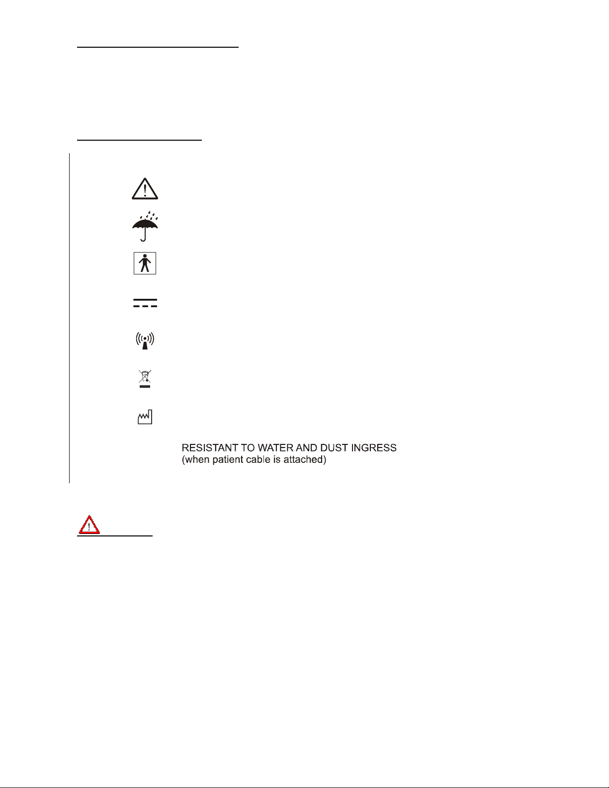
Explanation of Symbols
IP54
READ MANUAL FIRST
KEEP AWAY FROM MOISTURE
TYPE BF DEVICE
DC CURRENT
NON-IONIZING RADIATION
ELECTRONIC EQUIPMENT
DISPOSE OF PROPERLY
MANUFACTURER / MANUFACTURE YEAR
Warnings
1. This device captures and presents data reflecting a patient’s physiological condition that
when reviewed by a trained medical professional can be useful in determining a
diagnosis. However, the data should not be used as sole means for determining a
patient’s diagnosis.
Sirona User Manual Rev D02
-4-
Page 5
2. Use of accessories other than those recommended by IntriCon Datrix may compromise
product performance.
3. To maintain designed operator and patient safety, any peripheral equipment and
accessories that can come in direct patient contact must be in compliance with IEC
60601-1.
4. Hardware is designed to meet or exceed IEC 60601-1-2, however some environmental
electrical interference may cause an artifact in the ECG. The quality of ECG signals may
be adversely affected by electromagnetic interference from environmental sources
resulting in non-physiological waveforms with the potential for misinterpretation.
5. This device is not intended for use during an MRI.
6. Before performing defibrillation or applying any high frequency surgical equipment to a
patient, remove SIRONA leads and electrodes from the chest area. Cable leads or
electrodes trapped under defibrillator pads or paddles during defibrillation or electrodes in
contact with high frequency electrosurgical equipment can cause patient burns.
7. Once one or more SIRONA patient leads are connected to a patient, do not allow patient
leads to meet with any grounded or live parts. Contact could cause unacceptable levels
of electrical current to flow to the patient.
8. The equipment is not intended for infants weighing less than 10 kgs.
Cautions
1. Although the plastic enclosure is designed for a clinical environment and can resist
moisture, neither the device nor patient cables should be subjected to autoclaving or
steam cleaning.
2. Recommended cleaning procedure is to wipe the exterior surfaces with a cloth
dampened with warm water and mild detergent solution and then dry with a clean soft
cloth.
3. No serviceable parts are inside. The case cannot be opened without destroying it.
4. Do not pull or stretch patient cables, as this could result in mechanical and/or electrical
failures. Store patient cables after use by forming them into a loose loop.
5. Align patient cable connector key and SIRONA key before plugging in patient cable.
Forcing misaligned connectors can damage connector pins.
6. Avoid shock or sudden impact.
Notes:
1. Excessive patient movement could interfere with the operation of the device.
2. Proper patient preparation is important to successful application of ECG electrodes and
operation of the device.
3. This device complies with part 15 of the FCC Rules. Operation is subject to the following
two conditions: (1) This device may not cause harmful interference, and (2) this device
must accept any interference received, including interference that may cause undesired
operation. Changes or modifications not expressly approved by IntriCon for compliance
could void the user’s authority to operate the equipment.
4. This equipment has been tested and found to comply with the limits for a Class B digital
device, pursuant to part 15 of the FCC Rules. These limits are designed to provide
reasonable protection against harmful interference in a residential installation. This
equipment generates, uses and can radiate radio frequency energy and, if not installed
and used in accordance with the instructions, may cause harmful interference to radio
communications. However, there is no guarantee that interference will not occur in a
particular installation. If this equipment does cause harmful interference to radio or
television reception, which can be determined by turning the wireless transmission off
and on,then the user is encouraged to consult the dealer.
Formatted: Bullets and Numbering
Sirona User Manual Rev D02
-5-
Page 6
Section 1: Introduction
This manual is written for clinical professionals. It is assumed that the reader has a working
knowledge of medical terminology and procedures as required for monitoring cardiac patients.
Purpose of the User Manual
The User Manual describes how to safely operate the SIRONA Holter/Event recorder, Smart
Dock and linkStream. In the manual, the following are described:
Preparing the device for use
Understanding and using the keyboard
Acquiring and storing ECG data
Transmitting stored ECG data
Maintenance
System Description
The SIRONA Holter/Event recorder is a portable, battery-operated ambulatory ECG recorder
used by trained technicians to collect ECG data from patients in a clinical, point-of-care or
outpatient setting. SIRONA provides ECG waveform analysis and automated transmission of
ECG data for review by a physician or other qualified professional. ECG data is stored on an
internal SD card and can be accessed through the Smart Dock interface or by transmitting the
data over a telephone line. Smart Dock is an interface between a PC based application called
Sirona Viewer and the SD card in Sirona. Smart Dock has two functions –
linkStream is an accessory which provides the convenience of checking lead hook-up wirelessly.
1) Charge the battery in Sirona
2) Access the data stored on the SD card in Sirona
Deleted: ¶
Deleted: ¶
Section 2: Getting Started
Batteries
The Sirona uses an internal lithium polymer battery that is not accessible in the field. The battery
is designed to last for the life of the product.
Caution: THE BATTERIES USED IN THIS DEVICE MAY PRESENT A FIRE OR
CHEMICAL BURN HAZARD IF MISTREATED. DO NOT DISASSEMBLE, HEAT
ABOVE 100 C (212 F) OR INCINERATE.
Caution: DISPOSE OF ALL BATTERIES IN ACCORDANCE WITH ALL
APPLICABLE LOCAL REGULATIONS
KEEP AWAY FROM CHILDREN.
Sirona User Manual Rev D02
-6-
Deleted: IRONA
Page 7
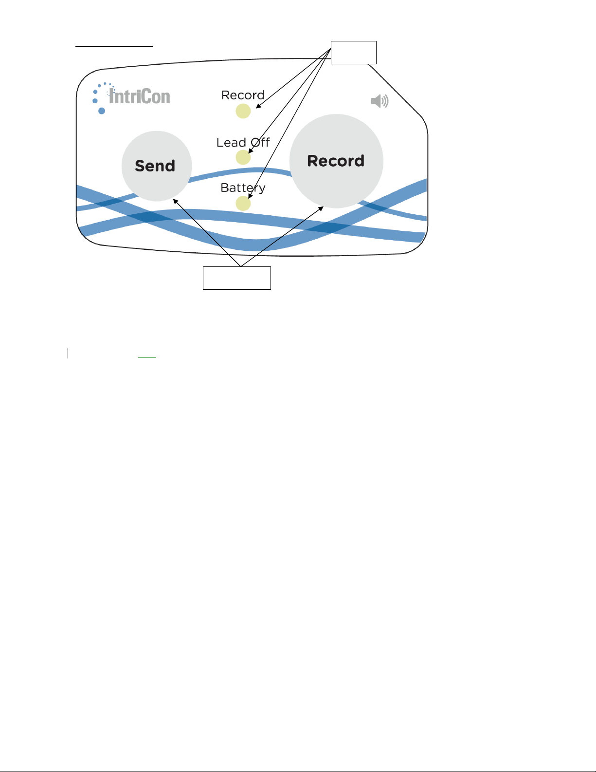
Front Panel
LED
The Sirona front panel contains two buttons and five LED lights (Light Emitting Diodes) as
follows:
Record Button
Send Button
Record Green or Red LED
Lead-off Red
Battery Green or Red LED
LED
Button
Sirona User Manual Rev D02
-7-
Page 8

Section 3: Initial Device Setup
Setting Parameters
One of the advantages of this device is that it can easily be configured to work in different modes,
and with different operational parameters. In order to enable this, the device has an internal nonvolatile microSD card where it will store configuration parameters. These parameters are
retrieved from microSD card upon device start-up.
Device ID is set by the manufacturer . The device ID is secured from accidental modification. It is
readable but not modifiable by the cardiac technician. A technician can read and modify several
parameters before connecting the device to the patient. This configuration is done using the
Smart Dock docking station, coupled with the Sirona Viewer PC application.
Examples of parameters which can be modified
- Recording length
- Pre-trigger time length
- Post-trigger time length
- Recorded Event Threshold for LED and Audible Alarm: number of recordings that will
trigger LED to flash periodically to inform the patient that he should send data to the
monitoring center.
- Audible Alarm Enable: Enable/disable an audible alarm to the patient when the number of
recorded events reaches the preset limit.
- Tachycardia threshold
- Bradycardia threshold
- Cardiac Pause threshold
Configuration
The device is designed to use several cables configurations as listed below in Error! Reference
source not found.. The device detects the type of cable attached and configure itself
accordingly.
are:
Deleted: used
Sirona User Manual Rev D02
-8-
Page 9

Section 4: Connecting Devices
4.1 Attaching Recorder to Patient
Patient Cable
The Patient cable connects to the Walta
cable is keyed for proper alignment. Be sure to align the key. Do not force a cable into position.
Use only IntriCon Datrix cable part numbers listed in table 1.
connector on the side of the SIRONA recorder. The
Patient Preparation
Note: Proper patient preparation and electrode placement are important for acquiring a
1. Prepare the electrode site by removing oils and lotion from the skin. If necessary, shave
the area where electrodes will be placed.
2. Clean the skin at the placement site with an alcohol prep pad.
high quality ECG.
3. Dry the area with a lint-free cloth.
4. Use Silver Chloride disposable electrodes designed for 24 hour Holter/Event monitoring.
Do not use 12-lead ECG or Stress Test Electrodes.
Patient Hookup
In order to obtain a high-quality ECG signal it is necessary to maintain good electrical contact
between the electrodes, patient cables and the patient’s skin. A suggested electrode placement
is shown in the diagram below. However, it is up to the physician to make the final placement
determination.
Deleted: Attaching Recorder to
Patient
Deleted: circular
Deleted: The recorder’s ECG display
screen can be used to verify a proper
patient hookup.
Warning: CONDUCTIVE PARTS OF ELECTRODES AND ASSOCIATED
CONNECTORS, SHOULD NOT CONTACT OTHER CONDUCTIVE P ARTS.
Sirona User Manual Rev D02
-9-
Page 10

3-Lead 1-Channel Electrode Placement
Read and follow instructions included with the electrodes.
1. Check the patient cable for damage or wear. Replace if necessary. Use Silver Chloride
disposable electrodes designed for 24 hour Holter/Event monitoring.
2. Place the electrodes onto the ECG leads.
3. Remove the backing from the pre-gelled disposable electrode.
4. Firmly place an electrode on each of the prepared skin surface sites. Dispose of any
electrode that does not properly adhere to the skin.
Warning: ECG REPORTS MUST BE READ BY A PHYSICIAN WHO IS TRAINED
TO INTERPRET AN ECG STUDY.
4.2 Connecting Smart Dock to a PC or to a wall socket using a
wall adapter
The Smart Dock is connected to a PC through a mini-USB to USB cable. The miniUSB end plugs into the Smart Dock and the USB end plugs into the PC or to a wall
adapter ( only when the Smart Dock is being used to charge the Sirona )
Sirona User Manual Rev D02
-10-
Page 11

4.3 Connecting the linkStream to a PC
The linkStream is connected to a PC through a mini-USB to USB cable. The mini-USB end
plugs into the linkStream and the USB end plugs into the PC
Section 5: Instructions for Use
5.1 Instructions for Patient
Before the patient leaves the office inform the patient about:
a) Proper use of the Record button and patient diary.
b) Transmitting ECG by TTM.
c) Light message displays
5.2 Instructions for Technician
Before putting the Sirona on the Smart Dock make sure the Sirona is in docking mode.
Sirona can be put in docking mode by pressing the Send and Record button simultaneously
for 5 seconds.
Start Up
Upon the connection of a cable, the SIRONA performs a system check and briefly flashes each
LED. It will then sound three tones using the speaker.
RECORD Button
The event button is the large round Record button on the device with a raised ring around it.
Press the Record button to store ECG data before and after the button press to the SD card. The
event time, when used in conjunction with a patient diary, provides a physician with the ability to
correlate patient symptoms with the ECG data.
SEND Button
The recorder will sound an audible alert when the number of events stored is equal to or greater
than the number previously set in the event threshold option. The patient must contact the call
center using a traditional land line. After the technician answers, the patient will be instructed to
hold the Sirona’s speaker up to the phone’s mouthpiece and
for 5 seconds. This will transmit the stored events to the doctor or service via Trans-Telephonic
Monitoring (TTM). The unit should be held up to the phone until the sound stops. When the
sound stops the patient should get back on the phone to talk to the technician. The technician
will then inform the patient of a successful transmission or instruct the patient to repeat the
process in the case of an incomplete transmission.
Heart Rate and Pause Calculation
The method used by the Sirona device to detect beats and derive heart rates for preprocessing
uses digital filtering and peak detection to create event vectors. The event vectors are further
processed using decision rules based on MIT/BIH database testing. Once an ECG complex has
been identified, a corresponding time is logged in milliseconds. The distance between each ECG
complex is used to calculate heart rate.
Pauses are classified when the interval of any beat is longer than the user specified threshold for
pause and is less than 30000 milliseconds.
then press and hold the Send button
Deleted: Page Break
Deleted: Patient
Deleted: ¶
Formatted: Bullets and Numbering
Deleted: . The Green Record LED
will flash a number of times
corresponding to the number of
recordings saved in memory
Deleted: mouthpiece and
Sirona User Manual Rev D02
-11-
Page 12

Smart Dock Operation
When Sirona is placed on the dock Smart Dock will charge battery. The charging status is
indicated by the battery LED on Sirona. The table in charging section below explains the battery
LED behavior.
To extract data from the SD card in the Sirona. Put the Sirona in “dock mode” by pressing
“Send+Record” together for 5 seconds. Place the Sirona on the Smart Dock. Open the Sirona
Viewer application on the PC and hit the “Save Holter Data” tab to save the data as a bin file.
linkStream Operation
After connecting the linkStream to the PC, open the Sirona Viewer application on the PC. Press
“Send” button on the Sirona for more than 5 seconds to start wireless transmission mode. On the
Sirona Viewer hit the “Scan for device” button. And then press Start ECG to see the signal that is
being wirelessly transmitted by the Sirona.
Press “Stop ECG” button to stop wireless ECG transmission.
Sirona User Manual Rev D02
-12-
Page 13

SIRON A Patient Interface Light Signals
There are several messages that could appear to alert you that action may be required, or simply
to alert you that an error has occurred. These messages include:
LIGHT MESSAGE ACTION
Battery LED solid Red when
device is on the Smart Dock
Battery LED off when device
is on the Smart Dock
Battery LED flashes green
every 10 seconds
Battery LED flashes red
every 2 seconds
Battery LED flashing red
every 500ms when on the
Smart Dock
Lead-off LED flashes red
every 2 seconds
Record LED lights up green
for 5 seconds
Record LED flashes red
continuously
Battery is charging
Battery is fully charged
Device is functioning normally None
Low Battery
Faulty Battery Contact technician/service
Indicated lead disconnected or
poor patient connection
Record button has been pressed None
Recording
error Contact technician / service
Leave the device on the Smart
Dock until the Battery light turns
off
Remove the device from the
Smart Dock
Charge the Sirona by placing it
on the Smart Dock
Check lead / electrode
Deleted: flashes green every 0.5
seconds
Deleted: becomes solid green
Deleted: solid green
Deleted: Record LED flashes green
Deleted: System
... [1]
Sirona User Manual Rev D02
-13-
Page 14

Section 6: Device Maintenance
Inspection and Cleaning
Routine inspection will help maintain the safety and performance of your SIRONA Holter/Event
recorder, Smart Dock and linkStream
identify any damage or excessive wear.
The outside surfaces can be cleaned with a cloth dampened with a mild soap and water solution.
Do not dispose of the unit
(WEEE) regulations for your area require.
in trash. Dispose of as the Waste Electrical and Electronic Equipment
Caution: DO NOT IMMERSE THE DEVICE IN LIQUID!
Caution: DO NOT CLEAN THE PATIENT CABLES WITH ALCOHOL. DO NOT
AUTOCLAVE THEM, OR USE ULTRASONIC CLEANERS.
Caution: DO NOT USE ANY HARSH CHEMICALS SUCH AS ACETONE,
AMMONIA OR IODINE TO CLEAN THE SIRONA.
Testing
The SIRONA executes a self-diagnostic check at these three times:
Any errors in the unit’s subsystems will be reported with an appropriate error message. If error
messages persist contact your IntriCon Datrix service representative. There are no user
serviceable parts in the SIRONA. The unit must be returned to IntriCon Datrix for service.
The SIRONA may also be tested by attaching the patient leads to a commercially available ECG
simulator and verifying each lead has amplitude and morphology as described in the simulator’s
manual. Excessive artifact usually indicates the patient cable needs replacing. Use only
replacement cables purchased from IntriCon Datrix.
a. At power-up
b. At the insertion of any cable
c. Upon removing the PWM device from the Smart Dock
d.
. Before operating the device perform a visual inspection to
Deleted: unit
Sirona User Manual Rev D02
-14-
Page 15

Charging
The Sirona should only be charged with equipment supplied by Intricon Datrix (Model Number –
RX 92446-0009 and Model Number – RX92598) intended for that purpose. The charging cable is
attached to either a PC or a wall adapter through USB on one end and through a Walta connector
to the Sirona on the other end, The Smart Dock(Model Number RX92446-0009) and Charging
cable (Model Number RX92598) should only be used with the wall adapter(Model Number
RX83103) when they are connected to the wall adapter through the USB cable.
Patient Worn Module will inform the user of the state of the charge of the battery as described
below:
Condition Battery LED Meaning
PWM on the Smart Dock Solid Red Charging
PWM on the Smart Dock Off Battery is fully charged
PWM on the Smart Dock Flashing Red Charger is not charging
PWM attached to a patient Green flash every 10
PWM attached to a patient Flashing Red Battery Voltage is LOW
PWM attached to charging
cable
PWM attached to charging
cable
seconds
Flashing Green Charging
Solid Green Battery is fully charged
Normal Operation
The lights on the
Storage
The Sirona, Smart Dock and linkStream should be stored between 10oC and 70oC and 10% to
95% relative humidity (non-condensing).
Transport
The Sirona, Smart Dock and linkStream should be transported between 10oC and 70oC and 10%
to 95% relative humidity (non-condensing).
Deleted: Flashing Green
Deleted: Solid Green
Comment [NP2]: Only true for
holter?
Deleted: 65
Caution: DO NOT IMMERSE IN WATER. KEEP AWAY FROM CHILDREN.
Sirona User Manual Rev D02
-15-
Deleted: ¶
Page 16

Sirona Accessory List
Description Part Number
3 Wire 1-Channel Event Cable 20" RX92368-001
5 Wire 2-Channel Holter Cable 20" RX92368-003
5 Wire 5-Channel Event Cable 20" RX92368-004
7 Wire 3-Channel Holter Cable 20" RX92368-005
3 Wire 1-Channel Event Cable 39" RX92368-006
5 Wire 2-Channel Holter Cable 39" RX92368-008
5 Wire 2-Channel Event Cable 39" RX92368-009
7 Wire 3-Channel Holter Cable 39" RX92368-010
5 Wire 3-Channel Holter Cable 20" RX92368-011
5 Wire 3-Channel Holter Cable 39" RX92368-012
2 Wire 1-Channel Event Cable 20" RX92368-013
2 Wire 1-Channel Event Cable 39" RX92368-014
3 Wire 2-Channel Event Cable 20" RX92368-015
3 Wire 2-Channel Event Cable 39" RX92368-016
Belt Clip
USB Cable
Wall Charger
Smart Dock
Charging Cable
RX82765-000
RX82929-000
RX83103-000
RX92518-000
RX92598-000
Sirona User Manual Rev D02
-16-
Page 17

SIRONA DATASHEET
General Specifications:
Input impedance: ≥ 10 MΩ
CMRR: > 60 dB
AC signal range: ± 5mV
DC signal range: ± 300mV
Bandwidth: 0.05 –40 Hz.
Sampling rate: 250 samples/sec.
Resolution: 10 bits
Battery: Lithium-Polymer rechargeable
Memory type: Flash
Waterproof rating: IP54 and brief immersion to 6” (when patient cable attached)
Lead status: Automatic lead-off detection
User alerts: LED indicators and audible alerts.
Wireless link option: 2.4Ghz PhysioLink internal transceiver
Operating temperature range: 0 –60 °C
Operating humidity range: 10 –90% r.h. (non-condensing)
Weight: 42 gr. (1.5 Oz.) excluding cable.
Holter Monitor Specifications:
2 or 3 channel recording depending on cable
24, 48 and 192 hour recording length
Typical battery life: 192 hours minimum between charges†
Upload to PC via smart-dock USB 2.0 accessory
Event Recorder Specifications:
1 or 2 channels depending on cable
Pre-trigger length: 30, 45, 60, 90, or 300 seconds*
Post-trigger length: 30, 60, 90, 120 and 180 seconds
Maximum number of events: 2048
Automatic arrhythmia detection: brady, tachy, pause and AF
Pacemaker pulse detection
TTM event data transmission
Typical battery life: 15
days between charges*
The Sirona
is compliant with IEC 60601-1 as a Type BF, internally powered device designed for
short time operation. The equipment is not suitable for AP or APG category environments.
The Sirona complies with Part 15 of the FCC rules.
Comment [NP3]: Ingress Protection
Rating: IP54 and brief immersion to
6”(when patient cable attached)
Deleted: X
Deleted: > 1000
Deleted: 30
Deleted: SIRONA
Sirona User Manual Rev D02
-17-
Page 18

Service/Technical Support:
¶
IntriCon Datrix
340 State Place
Escondido, CA 92029
Tel: 760-480-8874
Fax: 760-480-9474
Warning: THE SIRONA SHOULD NOT BE USED ADJACENT TO OR STACKED
WITH OTHER EQUIPMENT. IF ADJACENT OR STACKED USE IS NECESSARY, THE
SIRONA SHOULD BE OBSERVED TO VERIFY NORMAL OPERATIO N IN THE
CONFIGURATION IN WHICH IT WILL BE USE D.
Guidance and manufacturer's declaration - electromagnetic emissions
The Sirona is intended for use in the electromagnetic environment specified below. The
customer or user of the Sirona should assure that it is used in such an environment.
Emissions test Compliance Electromagnetic environment - guidance
Deleted:
Deleted: ¶
¶
¶
¶
RF emissions
CISPR 11
RF emissions
CISPR 11
Harmonic emissions
IEC 61000-3-2
Voltage fluctuations/
flicker emissions
IEC 61000-3-3
Group 1
Class B
N/A
N/A
The Sirona uses RF energy only for its internal
function. Therefore, its RF emissions are very low
and are not likely to cause any interference in
nearby electronic equipment.
The Sirona is suitable for use in all establishments
other than domestic and those directly connected
to the public low voltage power supply network
that supplies buildings used for domestic
purposes
Guidance and manufacturer's declaration - electromagnetic immunity
The Sirona is intended for use in the electromagnetic environment specified below. The customer or user of
the Sirona should assure that it is used in such an environment.
Sirona User Manual Rev D02
-18-
Page 19

Immunity test IEC 60601 test level
Conducted RF
IEC 61000-4-6
Radiated RF
IEC 6100-4-3
150 kHz to 80 MHz
80 MHz to 2.5 GHz
3 Vrms
3 V/m
Compliance
level
N/A
3V/m
80 MHz to 2.5
GHz
Electromagnetic environment - guidance
Portable and mobile RF communications
equipment should be used no closer to any part of
the Sirona, including cables, than the
recommended separation distance calculated for
the equation applicable to the frequency of the
transmitter.
Recommended separation dist a nce.
17.1
Pd
17.1
Pd
33.2
Pd
MH z800toMHz80
GHz 2.5 to MH z 800
where P is the maximum output power rating of the
transmitter in watts (W) according to the transmitter
manufacturer and d is the recommended
separation distance in meters (m).
Field strengths from fixed RF transmitters, as
determined by an electromagnetic site survey,a
should be less than the compliance level on each
frequency range.
b
Interference may occur in the vicinity of equipment
marked with the following symbol:
NOTE 1 At 80 MHz and 800 MHz, the higher frequency range applies.
NOTE 2 These guidelines may not apply in all situations. Electromagnetic propagation is affected by
absorption and reflection from structures, objects and people.
a
Field strengths from fixed transmitters such as base stations for radio (cellular / cordless) telephones and
land mobile radios, amateur radio, AM and FM radio broadcast and TV broadcast cannot be predicted
theoretically with accuracy. To access the electromagnetic environment due to fixed RF transmitters, an
electromagnetic site survey should be considered. If the measured field strength in the location in which the
Sirona is used exceeds the applicable RF compliance level above, the Sirona should be observed to verify
normal operation. If abnormal performance is observed, additional measures may be necessary, such as
reorienting or relocating the Sirona.
b
Over the frequency range 150 kHz to 80 MHz, field strengths should be less than [V1] V/m.
Sirona User Manual Rev D02
-19-
Page 20

Guidance and manufacturer's declaration - electromagnetic immunity
The Sirona is intended for use in the electromagnetic environment specified below. The customer or user
of the Sirona should assure that it is used in such an environment.
Immunity test
Electrostatic
discharge (ESD)
IEC 61000-4-2
Electrical fast
transient/burst
IEC 61000-4-4
Surge
IEC 6100-4-5
IEC 60601 test
level
+/- 6 kV contact
+/- 8 kV air
+/- 2 kV for power supply
lines
+/- 1 kV for input/output
lines
+/- 1kV line(s) to lines(s)
+/- 2kV line(s) to earth
Compliance level
+/- 6 kV contact
+/- 8 kV air
N/A N/A
N/A N/A
Electromagnetic environment -
guidance
Floors should be wood, concrete or
ceramic tile. If floors are covered with
synthetic material, the relative humidity
should be at least 30%.
Voltage dips, short
interruptions and
voltage variations
on power supply
input lines
IEC 61000-4-11
<5 % U
(>95% dip in U
for 0,5 cycle
40% U
(60% dip in U
T
T
)
T
)
T
for 5 cycles
70% U
T
(30% dip in U
)
T
N/A N/A
for 25 cycles
<5% U
T
(>95% dip in U
)
T
for 5 sec
Power frequency
(50/60 Hz)
IEC 61000-4-8
NOTE U
is the a.c. mains voltage prior to application of the test level
T
Power frequency magnetic fields
3 A/m 3 A/m
should be at levels characteristic if a
typical location in a typical commercial
or hospital environment.
Recommended separation dist anc e s between
portable and mobile RF communicatio ns e qui pme nt and t he Sir ona
Sirona User Manual Rev D02
-20-
Page 21

The Sirona is intended for use in an electromagnetic environment in which radiated RF disturbances are
controlled. The customer or the user of the Sirona can help prevent electromagnetic interference by
maintaining a minimum distance between portable and mobile RF communications equipment
(transmitters) and the Sirona as recommended below, according to the maximum output power of the
communications equipment.
Rated maximum output power
of transmitter
W
Separation distance according to frequency of transmitter
150 kHz to 80 MHz
80 MHz to 800 MHz
Pd 17.1
m
800 MHz to 5 GHz
Pd 17.1
Pd 33.2
0.01 0.12 0.12 0.23
0.1 0.37 0.37 0.77
1 1.17 1.17 2.33
10 3.69 3.69 7.37
100 11.67 11.67 23.3
For transmitters rated at a maximum output power not listed above, the recommended separation
distance d in meters (m) can be estimated using the equation applicable to the frequency of the
transmitter, where P is the maximum output power rating of the transmitter in watts (W) according to the
transmitter manufacturer.
NOTE 1 At 80 MHz and 800 MHz, the separation distance for the higher frequency range applies.
NOTE 2 These guidelines may not apply in all situations. Electromagnetic propagation is affected by
absorption and reflection from structures, objects and people.
Sirona User Manual Rev D02
-21-
Page 22

Page 13: [1] Deleted Nidhi Panday 7/24/2012 12:38:00 PM
Number of flashes corresponds
Record LED flashes green
to the number of stored
None
recordings[NP1]
 Loading...