


Table of Contents
........................................................................................................................................................................................................................................................................................................................
..........................................................................................................................................................................................................................................................................................................
.....................................................................................................................................................................................................................................................................................................
Connecting to Your PC
Connecting to Your Vehicle
ValueCAN Connection
neoVI Blue Connection
neoVI FIRE / RED Connection
neoVI Yellow
Application Software
Hardware Configuration
Firmware Updates
CAN networks
High Speed CAN
Medium Speed CAN
Single Wire CAN
Low Speed Fault Tolerant CAN
CAN Baud Rates and Bit Timing
Terminating a Dual Wire CAN Network
Terminating a Low Speed Fault Tolerant CAN Network
.................................................................................................................................................................................................................................................................................................
Bit Timing Calculator ...................................................................................................................................................................................................................................................................
J1850 VPW (Class 2)
J1850 PWM (Ford PWM)
J1708
..................................................................................................................................................................................................................................................................................................................
UART/ISO9141/KW2K/LIN
UART Timing
Initialization Waveforms
Error Checking
Local Interconnect Network (LIN)
LIN Slave Table ...........................................................................................................................................................................................................................................................................
...................................................................................................................................................................................................................................................................................
..........................................................................................................................................................................................................................................................................
...........................................................................................................................................................................................................................................................................
.........................................................................................................................................................................................................................................................................
.........................................................................................................................................................................................................................................................
.........................................................................................................................................................................................................................................................................................
....................................................................................................................................................................................................................................................................................
..............................................................................................................................................................................................................................................................................
...............................................................................................................................................................................................................................................................................
...........................................................................................................................................................................................................................................................................................
.................................................................................................................................................................................................................................................................................
...........................................................................................................................................................................................................................................................................
.................................................................................................................................................................................................................................................................................
........................................................................................................................................................................................................................................................
.....................................................................................................................................................................................................................................................
.........................................................................................................................................................................................................................................
............................................................................................................................................................................................................
..................................................................................................................................................................................................................................................................................
..........................................................................................................................................................................................................................................................................
.......................................................................................................................................................................................................................................................................
........................................................................................................................................................................................................................................................................................
....................................................................................................................................................................................................................................................................
.....................................................................................................................................................................................................................................................................................
...................................................................................................................................................................................................................................................
............................................................................................................................................................................................................................................................................................
1Overview
2Getting Started
3Hardware Basics
4
5
6
8
10
12
14
15
17
18In-vehicle Networks
19
20
21
22
23
24
25
26
27
28
29
31
32
34
35
36
37
38
39Hardware Features

neoVI Blue
neoVI FIRE / RED
neoVI Yellow
ValueCAN 3
SAE OBD Book
Internet Resources
Glossary
.........................................................................................................................................................................................................................................................................................................................
........................................................................................................................................................................................................................................................................................................
Theory of Operation
LED
.........................................................................................................................................................................................................................................................................................................
General Purpose IO
DAQ Pacer Clock
Specifications
Hardware Settings
General Purpose IO
Specifications
Hardware Settings
LED Blinking
....................................................................................................................................................................................................................................................................................................
General Purpose IO
Specifications
Hardware Settings
LED Blinking
.....................................................................................................................................................................................................................................................................................................
General Purpose IO
Specifications
..............................................................................................................................................................................................................................................................................................................
..............................................................................................................................................................................................................................................................................................
............................................................................................................................................................................................................................................................................................................
............................................................................................................................................................................................................................................................................
............................................................................................................................................................................................................................................................................
................................................................................................................................................................................................................................................................................
.......................................................................................................................................................................................................................................................................................
...............................................................................................................................................................................................................................................................................
.........................................................................................................................................................................................................................................................................................
............................................................................................................................................................................................................................................................................
.......................................................................................................................................................................................................................................................................................
........................................................................................................................................................................................................................................................................................
40
41
44
45
47
48
50
51
52
54
56
57
59
60
62
63
57
64
65
66
67Related Info
68
69
70
71Contact

Hardware O verv iew
Ma in
ne o VI a nd Valu eC AN ha rd ware from I ntre p id C ontro l System s o ff er a way to inte rfa ce you r P C to a varie ty o f d if fe ren t ne twork s co m m on ly us e d in to day' s ve hicles . Us ing ne o VI o r Valu e C AN d e vice s, yo u ca n m onitor a n um ber
of d iff eren t n etwork s s im ultane o us ly.
Mo st neo VI d e vice s con ne ct to the v eh icle thro ug h a 25 p in DSUB con ne cto r while Valu eC AN de vice s co nn ect throu gh a 9 p in DSU B con ne cto r. ne oVI an d Valu e C AN devi ces ca n s im ultan e ou sly re a d an d tra ns m it m essa ge s o n all
of its co n ne cte d ne twork s, tim e-s ta m p ev en ts , a n d tran sf e r the me s sa g es to the P C .
Ha rdware co n fig ura tio n ca n be d o ne in Ve hicle Sp y o r th rou gh th e u se o f a h ard ware e xplo re r. T h e ha rd ware ex p lo rers a llo ws yo u to s e tup b a ud ra te s, e na b le /disa b le n etwork s a nd co ntrol de vice be havi or.
Figure 1 - Intrepid Control Sys tem 's Vehicle Int erf aces.
neo VI D ocumenta tion - (C) Copyright 2000-2019 Intrepid Control Sys tem s, Inc.
La st Up d ate: Tues day, J anuary 17, 2012
Intrepid Hardware Help Overview
1 / 71

Gett ing Start ed
Ma in
Inst alling Software and Configura tion Tools
The first step to using the API, is installing the needed drivers and dlls. T his can be done in a few different ways. Installing Vehicle Spy 3 (full and free version) or the API install kit found
on the CD that shipped with t he hardware will take care of this step. Software can also be found on support page of Intrepid Control Syst ems Website.
From the CD that shipped with t he unit, run the icsAutoPlay.exe from the root of the disc (if it does not start automatically). This will give you the option of installing Vehicle Spy 3 or t he
API install kit. From the Website, the following links will have t he latest software.
-Vehicle Spy 3 Trial includes everything in the API install kit and has Vehicle Spy 3 Trial.
-API install kit for RP1210, J2534, and Intrepid Controls Systems' API.
Inst alling the neoVI dev ice on USB
Next, verify that you have the following minimum system requirement s:
One free USB port
Windows XP (SP3), Vista, 7, 8, 8.1, or 10 (Windows RT is not supported)
If Veh icle S py 3 is in sta lle d , t he h a rdware d rive rs are a ls o in stall ed . W hen a d e vice is p lu gg e d in, W in do ws s ho u ld re cog ni ze it a nd f ini sh th e driver insta ll.
Inst allation Support
If you have any problems installing neoVI or ValueCAN devices, please c all Intrepid Control Systems, Inc. at 810-731-7950.
Vehicle Conne ctions
ne o VI a nd Val ue C AN d evice s inclu d e a copy of th eir p ino u ts on th e d ev ice. Also, please see the neoVI user documentat ion.
A dditional Inf ormation
Please review t he following sources for more information on the neoVI vehicle interface.
De scription Locat ion
ne o VI O nline D ocu m e nta tio n In stalled with neo VI Ex plore r
ne o VI We bsite http :/ /www.intre pi dcs .co m /neo vi/
Veh icle Sp y 3 web s ite http :/ /www.intre pi dcs .co m /vs py/
neo VI Doc ument ation - (C) Copyright 2000-2019 Intre pid Control Syst ems, Inc.
La st Up d ate: Tues day, May 31, 2016
Intrepid Hardware Help Getting Started
2 / 71

neoV I Bas ics
Ma in
A pplies to
neoV I Blue, neoVI Red, neoVI FIRE , neoVI Ye llow, and ValueCA N
To us e n eo VI o r Value C AN d e vice s the f ollo wing ste p s are n e ed e d:
1) co nn ect to yo ur PC
2) C on nect to yo ur veh icle or d e vice
3) s etu p th e de vice
4) use a p pli cati on s o ftware to d o yo ur tas k .
neo VI Doc ument ation - (C) Copyright 2000-2019 Intre pid Control Syst ems, Inc.
La st Up d ate: Thursday, July 09, 2009
Intrepid Hardware Help Hardware Basics
3 / 71

Connect ing To Your PC
Ma in
A pplies to
neoV I Blue, neoVI Red, neoVI FIRE , neoVI Ye llow, and ValueCA N
Th e P C co nn ection to th e hard ware is USB . If th is is the first time that the hard ware ha s be e n co nn ecte d to the PC , W in do ws will a s k for drive s. Drive rs fo r the hard ware ca n be fo un d in two lo ca tio ns . T he Veh icle Sp y 3
ins ta lla tio n will ins tall th e d rive rs fo r the ha rdware. D rive rs ca n a ls o be f oun d on th e C D tha t s hi ps with the ha rdware .
neo VI Doc ument ation - (C) Copyright 2000-2019 Intre pid Control Syst ems, Inc.
La st Up d ate: Thursday, July 09, 2009
Intrepid Hardware Help Connecting to Your PC
4 / 71

Vehicle Conne ctor - OBD Pin-out
Ma in
A pplies to
neoV I Blue, neoVI Red, neoVI FIRE , neoVI Ye llow, and ValueCA N
Th e O BD-I I / J1 96 2 conn e ctor is p res e nt on eve ry no rth Ame rica n veh icle si nce 19 96 . T he co nn e ctor, d e fin e d in th e J1 96 2 spe cifi cati on , a llo ws yo u to co nn ect to the vehicle 's n etwork s yst em . T h is conn e ctor is us uall y fo un d
un de r the d a sh b oa rd (f ig ure 1 ).
Figure 1 - The J1962 Connector is usually locat ed under the dash board. Here we show the conne ctor on a 1999 GM Saturn SL.
Th e d ev ice pi n- ou t d e pe n ds o n the type of h ard ware yo u are co n ne ctin g and th e cab le y ou h ave. To se e th e pi n- ou t f or you r h a rdware s elect yo ur ha rdware type b e lo w.
- ValueCAN3
- neoVI Blue
- neoVI RED \ neoVI FIRE
- neoVI Yellow
neo VI Doc ument ation - (C) Copyright 2000-2019 Intre pid Control Syst ems, Inc.
La st Up d ate: Thursday, July 09, 2009
Intrepid Hardware Help Connecting to Your Vehicle
5 / 71

ValueCAN 3 Vehicle Side Conne ctions
Ma in
A pplies to
ValueCAN
Th e Val ue C AN 3 ha s a s ta nd a rd 9 p in C AN C o nn e ctio n. T his pin -o ut is in Ta b le 1.
Note tha t the Va lue C AN 3 co nn e ctor pi n-o u t is a ls o d ia gra m m e d on th e to p sti cke r o f the de vice .
Table 1 - The Value CAN 3 Connector Pin D escriptions
Pin Name De scription
1 Trigg e r P in Mis ce lla ne o us S ign a l 1
2 CAN 1 Lo w Hig h Sp ee d C AN L ow
3 GND Ele ctrical Gro un d
4 CAN 2 Lo w Hig h Sp ee d C AN L ow
5 GND ( Sh ie ld) Shi el d
6 GND Ele ctrical Gro un d
7 CAN 1 Hig h Hig h Sp ee d C AN H ig h
8 CAN 2 Hig h Hig h Sp ee d C AN H ig h
9 VBa tt Ele ctrical P os itive Su pp ly 6 .5 -4 0 VDC
Veh icle in te rfa ce con necto rs ca n be p urch ase d fo r th e Value C AN 3. For a comp le te list pl ea s e see I n trep id C o ntro l S yste ms web site. T he table s b el ow d es crib e two o f the com m o nl y u se d ca bl es f or the Va lueC AN 3 .
Figure 1 - The OBD -I I / J1962 Connector Ve hicle End View
Table 2 - The Value CAN 3 OB DI I Connector Pin D escription
Pin OB DI I Pin Value CAN 3 Name
6 7 CAN 1 Hig h
14 2 C AN 1 L ow
3 8 CAN 2 Hig h
11 4 C AN 2 L ow
16 9 V Batt
5 3 GND
4 5 GND ( Sh ie ld)
Table 3 - The Value CAN 3 J1939-RP1210 Conne ctor P in Description
Pin Vehicle Pin Value CAN 3 Name
1/ A 3 B attery (-) Gro u nd
2/ B 9 B attery (+)
3/ C 7 C AN_H
4/ D 2 C AN L
5/ E 5 CAN Sh el d
Figure 2 - The J1939-RP1210 Connec tor Ve hicle End View
Intrepid Hardware Help ValueCAN Connection
6 / 71

neo VI Doc ument ation - (C) Copyright 2000-2019 Intre pid Control Syst ems, Inc.
La st Up d ate: Wednes day, January 09, 2013
Intrepid Hardware Help ValueCAN Connection
7 / 71

neoV I Blue Ve hicle Side Connect ions
Ma in
A pplies to
neoV I Blue
You ca n conn ect ne o VI to th e Veh icle via the 25 p in D-S ub co nn e ctor. All of th e Veh icle n e twork s an d po wer f or the ne o VI de vice itself co m e fro m th is co nn e ctor. A lis ting o f the pin s o f this co nn e ctor is provid e d in Ta ble 1 be lo w.
Note tha t the n e oV I con ne cto r p in- out is al so d ia gram m e d o n the b o ttom o f th e n eo VI d e vice .
Table 1 - The neoV I Connec tor Pin Descript ions
Pin Name De scription
1 SW C AN Sin gle Wire C AN
2 J1 85 0 VPW J1 85 0 VPW (C lass 2 )
3 LSFT CAN H Lo w Spe e d Fau lt To le ra nt CA N Hig h
4 LSFT CAN L Low Sp e ed Fa ult To le ran t C AN L ow
5 J1 85 0 PW M L J1 85 0 PW M (F ord SC P ) Lo w
6 J1 85 0 PW M H J1 85 0 PW M (F ord SC P ) Hig h
7 ISO L UAR T/I SO 91 41 /Ke yword Li ne " L"
8 ISO K UAR T/I SO 91 41 /Ke yword Bi- di rection al Li ne " K"
9 MI SC 3 Mis ce lla ne o us S ign a l 3
10 M IS C 4 Mis cel la ne o us Sign al 4
11 M IS C 5 Mis cel la ne o us Sign al 5
12 M IS C 6 Mis cel la ne o us Sign al 6
13 P W R GND Ele ctrical Gro un d
14 H S C AN H High Spe e d CA N Hig h
15 H S C AN L H ig h Spe e d C AN Lo w
16 M S C AN H Me d ium Spe e d CAN High
17 M S C AN L Me d ium Spe e d C AN Lo w
18 L IN LI N
19 J 17 08 H J1 70 8 Hig h
20 J 17 08 L J1 70 8 Lo w
21 M IS C 1 Mis cel la ne o us Sign al 1
22 M IS C 2 Mis cel la ne o us Sign al 2
23 S CI T x Not Us e d
24 S CI R x Not U se d
25 V BATT Electrica l P o si tive Su pply 7- 25 VD C
Figure 2 - The OBD -I I / J1962 Connector Ve hicle End View
Table 2 - OBD -II Pins and the ir corresponding neoVI signal
J1962 Pin J1962 Pin Description neoV I Connect ion neoV I Pin
1 Dis cretion a ry* (GM LAN SW C AN Li ne ) SW C AN 1
2 + line o f SAE J 18 50 J1 85 0 VPW or J 18 50 P W M H 2 or 6
3 Dis cretion a ry* (GM LAN MS CA N H) MS C AN H 16
4 Cha ss is Gro u nd Do n ot us e fo r n e oV I.
Intrepid Hardware Help neoVI Blue Connection
8 / 71

5 Sig na l Grou nd PW R GND 13
6 Dis cretion a ry* (GM LAN HS CAN H) H S C AN H 1 4
7 K L ine of I SO 914 1-2 ISO K 8
8 Dis cretion a ry*
9 Dis cretion a ry* (GM AL DL)
10 - l ine of SAE J1 85 0 J1 85 0 PW M L 5
11 Dis cretion a ry* (GM LAN MS CA N L) MS C AN L 1 7
12 Dis cretion a ry*
13 Dis cretion a ry*
14 Dis cretion a ry* (GM LAN HS CAN L) H S C AN L 15
15 L l ine of I SO 9 14 1-2 ISO L 7
16 Un -s witche d Vehicle Ba tte ry P o si tive VBATT 25
* Dis creti on a ry m e ans th at the J1 97 9 sp ecifica tio n le a ves t his p in fo r u se by the m an uf acture r.
neo VI Doc ument ation - (C) Copyright 2000-2019 Intre pid Control Syst ems, Inc.
La st Up d ate: Thursday, July 09, 2009
Intrepid Hardware Help neoVI Blue Connection
9 / 71

neoV I FI RE and neo VI RE D - Ve hicle Side Connections
Ma in
A pplies to
neoV I Red, and neoV I FI RE
You can con ne ct ne o VI to the Veh icle via the 25 p in D-Su b co n ne cto r. M os t o f the Veh icle ne twork s a n d p ower fo r the ne o VI d e vice itself com e from th is con ne cto r. A listin g o f th e p in s o f th is co nn e ctor is pro vid e d in Tab le 1
be lo w. A dd itio nal conn ecti on s a re fo un d on th e 9 p in D-S ub co nn e ctor. A lis ting o f the pin s o f this co nn e ctor is provid e d in Ta ble 2 b e low
Note tha t the n e oV I con ne cto r p in- out is al so d ia gram m e d o n the b o ttom o f th e n eo VI d e vice .
Table 2 - NeoVI F IRE and RED 25 pin Connect or Pin De scriptions
Pin Name De scription
1 SW C AN Sin gle Wire C AN
2 J1 85 0 VPW J1 85 0 VPW (C lass 2 )
3 LSFT CAN H Lo w Spe e d Fau lt To le ra nt CA N Hig h
4 LSFT CAN L Low Sp e ed Fa ult To le ran t C AN L ow
5 MS C AN H Med iu m Sp e ed C AN Hig h
6 MS C AN L M ed iu m Sp e ed CAN Lo w
7 ISO L UAR T/I SO 91 41 /Ke yword Li ne " L"
8 ISO K/L IN 1 UAR T/ ISO9 14 1/ Ke yword Bi- dire ctio nal Lin e "K "
9 DBG C LK Not Us e d
10 M IS C 1 Mis cel la ne o us Sign al 1
11 M IS C 2 Mis cel la ne o us Sign al 2
12 D BG Da ta Not Us ed
13 P W R GND Ele ctrical Gro un d
14 H S C AN H H ig h S pe e d C AN Hi gh
15 H S C AN L H ig h Spe e d C AN Lo w
16 H S C AN 2 H H ig h Spe e d C AN 2 Hi gh
17 H S C AN 2 L Hi gh Sp e ed C AN 2 L ow
18 M IS C 4 Mis cel la ne o us Sign al 4
19 H S C AN 3 H H ig h Spe e d C AN 3 Hi gh
20 H S C AN 3 L Hi gh Sp e ed C AN 3 L ow
21 T SY NC C LK H / C GI H CGI Hig h
22 T SY NC C LK L / C GI L CGI Lo w
23 M IS C 3 Mis cel la ne o us Sign al 3
24 D BG RESET Not Us e d
25 V BATT Electrica l P o si tive Su pply 6- 27 VD C
Table 2 - NeoVI F IRE and RED 9 pin Connect or Pin De scriptions
Pin Name De scription
1 LI N 1 LI N 1
2 LI N 2 LI N 2
3 LI N 3 LI N 3
4 LI N 4 LI N 4
5 GND Gro un d Re f ere n ce
6 MI SC 5 Mis ce lla ne o us S ign a l 5
7 MI SC 6 Mis ce lla ne o us S ign a l 6
8 NC No Co n ne ct
9 VBa tt O ut No C on ne ct
Intrepid Hardware Help neoVI FIRE / RED Connection
10 / 71

Figure 2 - The OBD -I I / J1962 Connector Ve hicle End View
Table 1 - OBD -II Pins and the ir corresponding neoVI signal
J1962 Pin J1962 Pin Description neoV I Connect ion neoV I Pin
1 Dis cretion a ry* (GM LAN SW C AN Li ne ) SW C AN 1
2 + line o f SAE J 18 50 J1 85 0 VPW 2
3 Dis cretion a ry* (GM LAN MS CA N H) MS C AN H 5
4 Cha ss is Gro u nd Do n ot us e fo r n e oV I.
5 Sig na l Grou nd PW R GND 13
6 Dis cretion a ry* (GM LAN HS CAN H) H S C AN H 1 4
7 K L ine of I SO 914 1-2 ISO K 8
8 Dis cretion a ry*
9 Dis cretion a ry* (GM AL DL) HS CAN 3 H 19
10 - l ine of SAE J1 85 0 HS CAN 3 L 20
11 Dis cretion a ry* (GM LAN MS CA N L) MS C AN L 6
12 Dis cretion a ry* HS C AN 2 H 16
13 Dis cretion a ry* HS C AN 2 L 17
14 Dis cretion a ry* (GM LAN HS CAN L) H S C AN L 15
15 L l ine of I SO 9 14 1-2 ISO L 7
16 Un -s witche d Vehicle Ba tte ry P o si tive VBATT 25
* Dis creti on a ry m e ans th at the J1 97 9 sp ecifica tio n le a ves t his p in fo r u se by the m an uf acture r.
neo VI Doc ument ation - (C) Copyright 2000-2019 Intre pid Control Syst ems, Inc.
La st Up d ate: Thursday, July 09, 2009
Intrepid Hardware Help neoVI FIRE / RED Connection
11 / 71
neoV I Ye llow Vehicle Side Conne ctions
Ma in
A pplies to
neoV I Ye llow
Th e n eo VI Ye llo w ha s a 1 5 pin C o nn e ctio n. T hi s pin -o u t is in Ta b le 1 .
Note tha t the n e oV I Yel low co nn e ctor pin -o ut is a ls o di ag ra m m ed o n th e bo tto m s tick e r o f the d e vice .
Table 1 - The neoV I Ye llow 3 Connector Pin De scriptions
Pin Name De scription
1 TS YNC C LK H T SY NC CL K H
2 TS YNC C LK L TSY NC CL K L
3 ISO L UAR T/I SO 91 41 /Ke yword Li ne " L"
4 MI SC DI O 1 Misce llan e ou s Sig na l 1
5 J1 93 9 2 H ( CA N 2 H) / J18 50 V PW H igh Spe e d CA N Hig h / J1 85 0 VPW (Class 2 )
6 GND Ele ctrical Gro un d
7 Shi el d Shi el d
8 V BAT T Electrica l P o sitive Sup ply 6-32 VDC
9 MI SC DI O 2 Misce llan e ou s Sig na l 2
10 J 19 39 2 L (C AN 2 L ) / I SO K Hig h Sp ee d C AN L ow / UA RT /I SO 9 14 1/Key word Bi-d ire ctio na l Lin e "K"
11 M IS C DI O 3 Mis ce lla ne o us S ign a l 3
12 J 19 39 1 L (C AN 1 L ) Hig h Sp ee d C AN L ow
13 J 19 39 1 H (C AN 1 H ) Hig h Spe e d C AN High
14 J 17 08 L (-) J1 70 8 Lo w
15 J 17 08 H (+) J1 70 8 Hig h
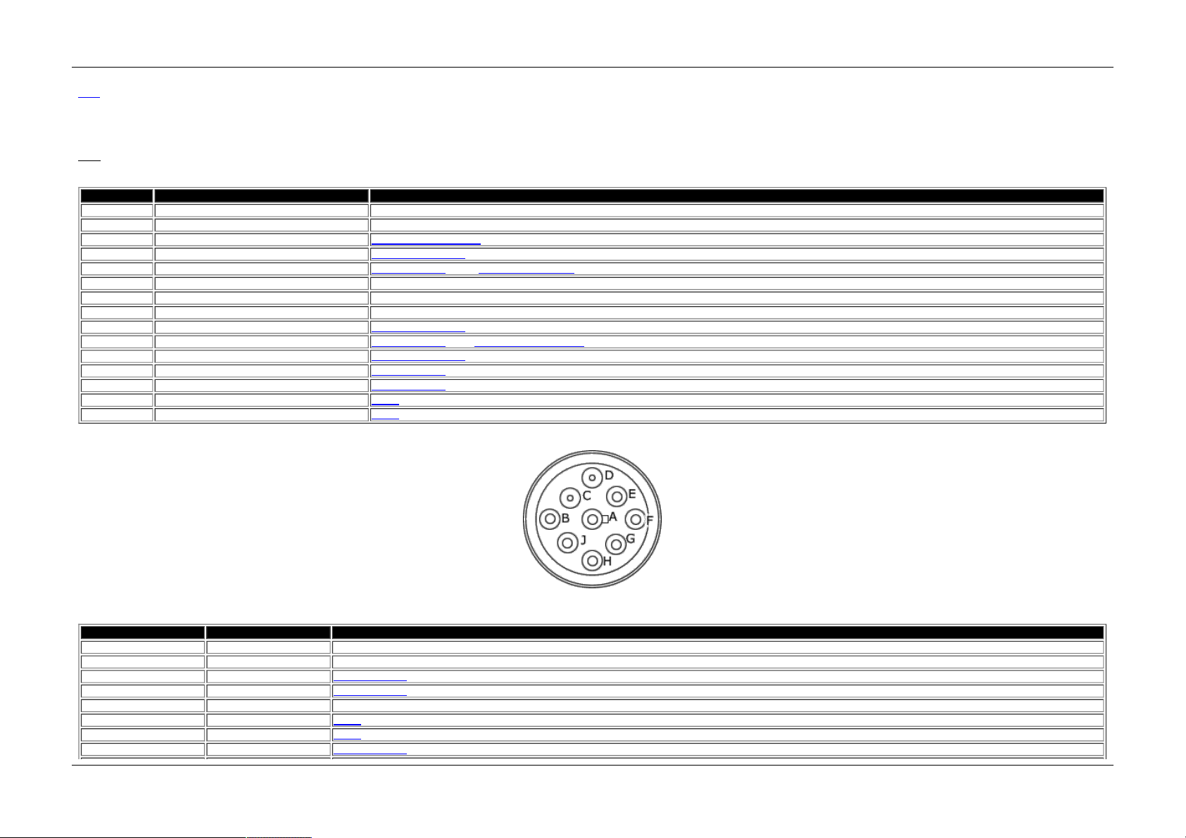
Figure 1 - The J1939-RP1210 Connec tor Ve hicle End View
Table 2 - The neoV I Ye llow J1939-R P1210 Conne ctor P in Description
De utsch P in Pin neoV I Ye llow Name
1/ A 6 Ele ctrical Gro un d
2/ B 8 Ele ctrical P os itive Supp ly 6 -3 2 VDC
3/ C 1 3 Hig h Sp ee d C AN H ig h
4/ D 12 H igh S pe e d CAN Lo w
5/ E 7 Sh ie ld
6/ F 1 5 J1708 H ig h
7/ G 14 J 17 08 Lo w
8/ H 5 H igh S pe e d CAN 2 Hig h
Intrepid Hardware Help neoVI Yellow
12 / 71

9/ J 10 H igh S pe e d CAN 2 Lo w
neo VI Doc ument ation - (C) Copyright 2000-2019 Intre pid Control Syst ems, Inc.
La st Up d ate: Thursday, July 09, 2009
Intrepid Hardware Help neoVI Yellow
13 / 71

A pplication Sof tware - neoVI
Ma in
A pplies to
neoV I Blue, neoVI Red, neoVI FIRE , neoVI Ye llow, and ValueCA N
To us e n eo VI o r Value C AN, you n e ed a p plicati on s o ftware . A pp lica tio n sof tware is s of tware that le ts yo u vie w Vehicle Network d a ta a s well as g e ne ra te it.
Th e u ltimate a pp lica tio n s o ftware fo r work in g with ve hicle n e twork s is Vehi cle Spy fro m In tre pid C on trol System s. It le ts you us e n e oV I a nd Valu eCAN a s a bu s m onitor, simula to r, a n d a flig ht re co rde r. M ore in fo rm ation can be
fo un d a t h ttp: //intre p idcs .co m /Vehicle Sp y/.
If a full ve rsion o f Vehi cle Sp y is n o t p urch as e d, a li m ite d fre e ve rsio n is inclu de d with the h a rdware . Th is s of tware le ts yo u do th e b as ics - vie w me s sa g e tra ffi c a nd g ene rate it.
Fin al ly, yo u ca n write yo ur o wn a p pli cati on so ftware . n eo VI inclu des an API fo r you to write yo ur own ne oVI a pp lica tio n s with La bVIEW, Vis ua l Ba si c, Borlan d C ++ Buil de r, L abW in do ws CV I, o r V isu a l C++. M o re in fo rm ati on on the
AP I, in clud in g ex am ples , can a ls o be fo un d in the In trepid API h elp which is in stal le d with Veh icle Spy. Th is is a ls o in sta lle d with the li m ite d fre e ve rsion o f Vehi cle Sp y.
neo VI Doc ument ation - (C) Copyright 2000-2019 Intre pid Control Syst ems, Inc.
La st Up d ate: Thursday, July 09, 2009
Intrepid Hardware Help Application Software
14 / 71

Hardware Configurat ion
Ma in
A pplies to
neoV I Blue, neoVI Red, neoVI FIRE , neoVI Ye llow, and ValueCA N
Ov erview
Ba sic ha rdware conf igu ra tio n fo r ne o VI and Valu e CA N is do n e throu g h Intre p id Hardware Ex plo re r. T his ca n be f ou nd in Veh icle Spy. This is d on e b y clickin g the "Se tup H ard ware " Butto n ( ) o r by s e le cting Setu p the n
Ha rdware f rom the m enu b a r (Fi gu re 1) . Cli cki ng o n the "Ha rd ware Setup ... " b utton will brin g up th e H ard ware Ex plo re r (f ig ure 2 ).
Figure 1 - Network Setup SpreadShee t
Intrepid Hardware Help Hardware Configuration
15 / 71

Figure 2 - neoVI Hardware Explorer
Connect ing to a neoV I
You can se le ct the de vice yo u want to con nect to by s el ecti ng i t in th e list o n th e le ft ( fig ure 2 : b ub bl e 1 ). T he "C o nn ect" bu tto n (f igure 2 : bu b ble 2) will co nn e ct to th e h ard ware a n d re ad the se ttin g s curre ntly s to red in t he
de vice . Th e sta tu s wind ow (figu re 2 : bu bb le 2) n oti fie s y ou if th ere a re any is s ue s talk ing to the h ard ware . Th e f irm ware ve rsi on s are sho wn un de r Firm ware (fi gu re 2 : bu bb le 4) . De vice se ttings ca n be s et to de fa ult s b y
click in g on th e Lo a d De fa ults bu tto n (fi gu re 2 : bu bb le 5 ) i n the u ppe r rig ht.
neo VI Doc ument ation - (C) Copyright 2000-2019 Intre pid Control Syst ems, Inc.
La st Up d ate: Thursday, July 09, 2009
Intrepid Hardware Help Hardware Configuration
16 / 71

Firmware Maintenanc e - neoV I
Ma in
Ov erview
Firm ware f or the ha rd ware is store d in the s o ftware us ed to co nn ect to the ha rdware . Ve hi cle Sp y, n eoVI H a rdware Ex p lo rer, an d cu sto m ap p lica tio ns u s ing the icsn e o4 0. dll a n d pro gra m m in g AP I a re a pp lication s th at will up da te
the firm ware in th e d evice. B y d e fa ult firmware i s au to m atical ly l oa d ed i f th e co nn e cting s o ftware d e te cts a diffe re nt ve rsio n in th e ha rd ware tha n wha t th e sof tware ha s .
Your Current Firm ware
W he n you co nn ect to yo ur h a rdware , neo VI Ha rd ware Explo re r will lis t th e curren t firmware in the n eo VI d evice (Fig ure 1: Bu bb le 4 ). I f the firm ware doe s no t m a tch the firm ware in th e sof tware , th e ve rsi on n um b er will be
fla g ge d re d. I f au to m at ic fi rmware up da te s a re dis a bl ed , firm ware ca n be up lo ad e d us in g the " Ma n ua l R e fl as h" b utton . After up da tin g the de vice s fi rmware , che ck yo u r ne twork s setting s to e ns ure tha t th e y a re co rrect.
Figure 1 - neoVI Hardware Explorer
neo VI Doc ument ation - (C) Copyright 2000-2019 Intre pid Control Syst ems, Inc.
La st Up d ate: Monday, March 09, 2009
Intrepid Hardware Help Firmware Updates
17 / 71

In-v ehicle Network s - neoVI
Ma in
ne o VI a nd Val ue C AN h as the ca pab ilit y to s im u lta ne o us ly acce ss a nu m be r o f in -ve hi cle ne twork s . T hes e n etworks a re s ho wn in ta b le 1 be low.
Each n etwork can b e e na b le d or dis a bled ( fig ure 1 ) in the ha rdware e x p lorer.
Figure 1 - Eac h Network can be enabled or disable d.
Table 1 - Indepe ndent Vehicle Networks in the neoVI D ev ice
Name Hardware De scription
Hig h Sp ee d C AN neoVI Blue, neoVI Red, neoVI FIRE, neoVI Yell ow, and ValueCAN CAN ne twork with o ptimi ze d h ard ware fo r h ig h sp eed
Me d ium Spe e d CAN neoVI Blue, neoVI Red, and neoVI FIRE Du al W ire C AN n etwork
Sin gle Wire C AN neoVI Blue, neoVI Red, and neoVI FIRE CAN Network with Sin g le W ire Tra ns ceive r
Lo w Spe e d Fau lt To le ra nt CA N neoVI Blue, neoVI Red, and neoVI FIRE CAN Network with Lo w Sp ee d Fau lt Tolera nt Tra ns cei ve r
J1 85 0 VPW (C lass 2 ) neoVI Blue, neoVI FIRE, and neoVI Yellow J1 85 0 VP W Network Tra n sce ive r
J1 85 0 PW M (F ord SC P ) neoVI Blue J1 85 0 PW M Ne twork Tran sceiv er
ISO9 14 1/ Ke yword 2K/ UA RT /L IN neoVI Blue, neoVI Red, neoVI FIRE, and neoVI Yellow UAR T network tran sce ive r
J1 70 8 neoVI Blue and neoVI Yellow J1 70 8 ne twork tra ns ce ive r
CGI neoVI FIRE Exp a ns io n Mo dule Ne twork
ne o VI De vice V irtua l Network
neoVI Blue, neoVI Red, neoVI FIRE, neoVI Yell ow, and ValueCAN
A " im a gin a ry" n e twork th at is use d to co ntro l n e oVI de vice fe ature s su ch as g e ne ra l p urpo se I O o r th e
LED
neo VI Doc ument ation - (C) Copyright 2000-2019 Intre pid Control Syst ems, Inc.
La st Up d ate: Tues day, J uly 07, 2009
Intrepid Hardware Help In-vehicle Networks
18 / 71

CA N Networks - neoV I
Ma in
A pplies to
neoV I Blue, neoVI Red, neoVI FIRE , neoVI Ye llow, and ValueCA N
Th e C AN co ntro lle rs us e d in ne o VI a nd Val ue C AN s up po rt a fe w dif fe rent CAN m od e s (fi gu re 1) . A s um m a ry o f the mo d e s are g ive n b el ow in ta ble 1.
Table 1 - CAN Controller Dev ice Modes
Mode Description
Norm a l M o de Norm a l C AN Co m m unica tio ns.
Lis te n O nly CAN R x o nly with n o e rror frames g e ne ra ted o r a ck no wled g es
Lo opb ack (Blu e O nl y) No Ne twork o pe ra tio n. All m e ss a ge s tra ns m itte d a re se e n a s rece ive d m e ss a ge s .
Lis te n All (Ex cep t Blue ) No Network o p era tio n . Al l m e s sa g es tra n sm itted a re s een a s re cei ved m essa ge s. All m es s ag e s are re ce ive d re ga rdl es s o f erro rs in fra m e
Dis a ble No Ne twork o pe ra tio n.
Figure 1 - Yo u can select the CA N controller mode in the neo VI Ex plorer.
neo VI Doc ument ation - (C) Copyright 2000-2019 Intre pid Control Syst ems, Inc.
La st Up d ate: Wednes day, March 11, 2009
Intrepid Hardware Help CAN networks
19 / 71

High Speed CA N - neoVI
Ma in
A pplies to
neoV I Blue, neoVI Red, neoVI FIRE , neoVI Ye llow, and ValueCA N
Th e ne o VI high sp e ed CAN cha n ne l is a n ISO 11 89 8 Dua l W ire C AN Phys ica l La ye r (8 2C2 51 ) CAN cha n ne l. Lik e a ll CAN C ha nne ls , th is cha n ne l has p rog ra m mab le b a ud rate/ bit tim in g an d C AN de vice mo de . Thi s chan nel is
fu nctio n al ity e q ui val en t to the m edi um sp e ed ch a nn el e x cep t f or tha t the n e oV I circuits f or hig h spe e d are o p tim iz e d.
Accord in g to the ISO 118 98 s pe cifi cati on , the e n ds o f the CAN ne twork ca bl ing s hou ld b e te rmi na te d. T his is de s cribe d in a s e pa ra te to pic.
neo VI Doc ument ation - (C) Copyright 2000-2019 Intre pid Control Syst ems, Inc.
La st Up d ate: Wednes day, March 11, 2009
Intrepid Hardware Help High Speed CAN
20 / 71

Medium Spee d CAN - neoVI
Ma in
A pplies to
neoV I Blue, neoVI Red, and neoVI FIR E
Th e n e oV I m e diu m sp e ed CA N cha n ne l is a n I SO 118 98 D ua l W ire C AN Ph ys ical L ay er (8 2C 2 51 ) CA N ch an ne l. L ik e a ll C AN Ch a nn els, th is cha nn e l ha s p rog ra mmab le b a ud ra te /b it tim in g an d C AN d e vice mod e . Th is cha nn e l is
fu nctio n al ity e q ui val en t to the h ig h sp e ed ch a nn el e x cep t f o r tha t the n e oVI circuits f or the hig h sp e e d cha nn e l a re o pti m ize d .
Accord in g to the ISO 118 98 s pe cifi cati on , the e n ds o f the CAN ne twork ca bl ing s hou ld b e te rmi na te d. T his is de s cribe d in a s e pa ra te to pic.
neo VI Doc ument ation - (C) Copyright 2000-2019 Intre pid Control Syst ems, Inc.
La st Up d ate: Thursday, July 09, 2009
Intrepid Hardware Help Medium Speed CAN
21 / 71

Single Wire CA N - neoVI
Ma in
A pplies to
neoV I Blue, neoVI Red, and neoVI FIR E
Th e n eo VI s in gle wire C AN ch an ne l is a GM W3089 / SAE J2 41 1 (Si lico n: TLE62 55 ) CA N cha nne l. Lik e a ll C AN C ha n ne ls , th is ch an nel ha s p rog ra m m ab le b a ud ra te /b it ti m ing a n d CA N de vice mod e .
Th e s in gle wire CAN ph ys ica l l ayer con ta ins thre e o p era tio n al m o de s . Th e y a re th e f ol lo wing 1) n orm a l com mu nica tio n m o de , 2) h ig h-vol tag e wak e u p m o de , a nd 3 ) hi gh -s pe e d m o de . T he de fa u lt ba ud rate is u se d for no rm a l
an d high -vo lta g e m o de s . For the h ig h-sp eed m o de, yo u ne e d to s pe cify a n ad d itio na l ba u d rate ( thi s is do n e o n t he H igh S pe e d Mo d e pa n el ).
ne o VI provid e s two m ode s fo r the h ig h sp eed s e ttin g, o ne is u s ed f or m on ito rin g hig h sp e e d an d the othe r is to op e rate as a te st to ol. G MW 3 08 9 req ui res a te st to ol to s witch i n a sp e cifie d te s t to o l re s isto r whe n tra ns m itting in
hig h s pe e d m od e .
neo VI Doc ument ation - (C) Copyright 2000-2019 Intre pid Control Syst ems, Inc.
La st Up d ate: Thursday, July 09, 2009
Intrepid Hardware Help Single Wire CAN
22 / 71

Low Speed Fault Tolerant CAN - neoVI
Ma in
A pplies to
neoV I Blue, neoVI Red, and neoVI FIR E
Th e n eo VI h a s an I SO 11 51 9 Lo w Spe e d Fau lt Tole ra nt C AN P hys ica l L a yer (T JA1 05 4) C AN ch ann el . L ik e a ll C AN Ch a nn el s, th is cha nne l h a s pro gram m a bl e ba u d rate / bit tim in g a nd C AN d e vice m o de .
Th e Lo w Sp ee d Fault Tol era n t C AN n etwork req ui res te rm in ation with spe cifi c re sis to rs. T his i s de scribe d in a s epa rate to pic.
neo VI Doc ument ation - (C) Copyright 2000-2019 Intre pid Control Syst ems, Inc.
La st Up d ate: Wednes day, March 11, 2009
Intrepid Hardware Help Low Speed Fault Tolerant CAN
23 / 71

CA N Bit Timing - neoVI
Ma in
A pplies to
neoV I Blue, neoVI Red, neoVI FIRE , neoVI Ye llow, and ValueCA N
Th e Ba ud Ra te o f e ach C AN n e twork is p rog ram ma bl e. n eo VI a llo ws y ou to s e le ct a d e fa ul t b au d rate fro m a li st or al lows you to sp e cify a cus to m b it ra te (fig ure 1 ).
W hil e the ne oVI exp lo rer gives y ou d e fa ult Ba ud R a te s to p ick fro m , you m ay n eed to h a ve s pe cific b it ti m ing o r a n oth e r b au d rat e. I f you h av e thi s, yo u m us t s pe cif y cu sto m b it tim in g. To d o thi s click e di t a s sh o w in fig ure 1 .
W he n yo u click "Edit" , yo u will s e e th e C AN Bit T im ing Dia lo g (fi gu re 2) . T h is di al og a llows you to en te r th e C NF1, C NF2, C NF3 pa ra m eters f or the MC P2510 C AN co ntro lle r. I nt rep id C ontro l S yste m s p rovide s a n a dd itio n al s of tware
uti lity to he lp yo u fi gu re ou t t he se va lue s . T h is uti lity is the MC P 25 10 Bit tim in g ca lculato r, you ca n la un ch this utility by click ing " La unch Bit Ti m ing C a lculator"
Figure 1 - neoVI lets specify a def ault or cust om baud rate/ bit timing.
Figure 2 - neoVI Custom Bit Timing Entry
neo VI Doc ument ation - (C) Copyright 2000-2019 Intre pid Control Syst ems, Inc.
La st Up d ate: Thursday, July 09, 2009
Intrepid Hardware Help CAN Baud Rates and Bit Timing
24 / 71

CA N Bit Timing Calculator - neoVI
Ma in
A pplies to
neoV I Blue, neoVI Red, neoVI FIRE , neoVI Ye llow, and ValueCA N
Th is to pi c co ve rs the M CP2 51 0 an d P IC m icro C o ntro lle r Area Ne twork (C AN) Bit Ti m ing ca lcu la tor. The u tilit y h el ps yo u setu p th e con figu rati on re gi ste rs o n the M icro chip M C P2 51 0 and P IC m icro s ta nd a lo ne Co n troll er Are a
Network ( C AN) co ntroll er.
Scree n 1 - Select Oscillator Freq and Controller A rea Network (CA N) Target Baud Rat e (click for large r image )
Th e fi rst ste p is to tell th e so ftware yo ur o s cilla to r fre q ue n cy a nd ta rg et C on tro lle r Are a Ne twork (C AN) ba ud rate . Th e n the s o ftware will de te rm ine the p o te ntia l Ba ud R a te P res ca le r (BRP ) and n um b er of time qu a nta ( Tq )
req uired ( scre e n 1).
Th e n ex t ste p is to a d jus t th e va rio us p aram e te rs of th e bit timi ng . Th es e in clu de p ro pa g ati on d e la y, ph a se 1 s e gm ent width, p ha s e 2 se g m en t wid th, a nd s ynch roniz a tio n jum p width. T he actu a l b it t im ing i s dis p la ye d
gra phica lly (s cree n 2) .
Scree n 2 - Adjust ment of v arious bit timing parame ters (click fo r larger image)
Th e ca lcul ato r will che ck yo ur se tu p ve rsu s diffe re nt rule s fo r the va rio us tim ing . W he n yo ur se tup che cks ou t, you ca n ge n e rate a se tu p rep ort.
Th e s etup re po rt i nclu de s yo u r com ple te s etu p . T hi s includ es the b it-tim ing, a grap h of b it tim ing , an d th e va lue s for the C NF1 , C NF2 , a n d CNF3 re giste rs fo r y ou to co p y in yo u r so u rce cod e . S ee the e x a m ple HT ML he re
(M CP 2 51 0R e po rt.h tm ).
Links
Micro chi p Tech no lo g y h ttp: //www.microch ip.com (Ven do r o f the MC P25 10 )
neo VI Doc ument ation - (C) Copyright 2000-2019 Intre pid Control Syst ems, Inc.
La st Up d ate: Thursday, July 09, 2009
Intrepid Hardware Help Bit Timing Calculator
25 / 71
Terminating a Dual Wire CAN Network - neoVI
Ma in
A pplies to
neoV I Blue, neoVI Red, neoVI FIRE , neoVI Ye llow, and ValueCA N
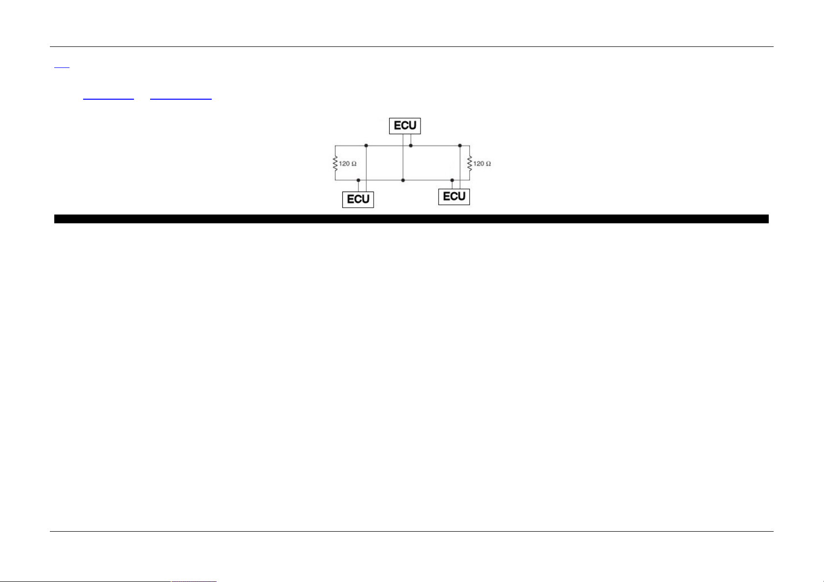
Bo th the H ig h Spe e d C AN a nd M e diu m Spe e d CA N cha n ne ls re qu ire th e e nd s o f th e C AN n e twork to be termi na te d with a 1 20 o h m re sis to r.
Typi cally, if yo u are co n ne ctin g to a e xisti ng C AN n e twork the s e te rm ina tion re si sto rs will b e p res e nt. If yo u a re bu ild in g a te st ne twork yo u m a y h a ve to in stall th es e re si sto rs .
neo VI Doc ument ation - (C) Copyright 2000-2019 Intre pid Control Syst ems, Inc.
La st Up d ate: Thursday, July 09, 2009
Intrepid Hardware Help Terminating a Dual Wire CAN Network
26 / 71

Terminating a Low Speed F ault Tolerant CA N Network - neo VI
Ma in
A pplies to
neoV I Blue, neoVI Red, and neoVI FIR E
Th e Lo w Sp ee d Fault Tol era n t C AN n etwork req ui res e a ch no de to be term inated with two re s istors . T h e size o f the res is tors a re b as e d on th e o ve ral l n um ber of n od e s in the ne twork .
Each n od e s te rmina tio n re sis to rs are in pa ra lle l. Th e re su ltin g resis ta nce f or all o f the res is tors s ho u ld be be twee n 10 0 an d 50 0 oh m s . n e oVI s h ips with 51 0 ohm re s istors in stal le d.
Th e te rm in ati on re sisto rs a re insta lle d in s o cke ts o n the ne o VI prin te d circui t b oa rd . T he y can b e re pl ace d e asil y. Pl ea s e see the h a rdware s e ttings to pi c fo r info rm a tio n on h o w to ch ang e the term ination re s istors .
Pl ea s e s ee the T JA1054 d ata sh ee t an d relate d a pplication n ote s f or furth e r in fo rm at ion o n Lo w Sp ee d Fau lt Tol era nt C AN n et work term ination a n d ne twork d esig n.
neo VI Doc ument ation - (C) Copyright 2000-2019 Intre pid Control Syst ems, Inc.
La st Up d ate: Thursday, July 09, 2009
Intrepid Hardware Help Terminating a Low Speed Fault Tolerant CAN Network
27 / 71

J1850 VP W (Class 2) - neoVI
Ma in
A pplies to
neoV I Blue, neoVI FIRE, and neoV I Ye llow
Th e n etwork pro tocol do e s no t us e a s pe cifi c J1 85 0 pro to col chi p, it ge n era te s the VPW sym b ols with a s o ftware p e riph e ral. Th ere are n o s ett ing s fo r th is n etwork .
neo VI Doc ument ation - (C) Copyright 2000-2019 Intre pid Control Syst ems, Inc.
La st Up d ate: Wednes day, March 11, 2009
Intrepid Hardware Help J1850 VPW (Class 2)
28 / 71
J1850 PWM (Ford SCP ) - neoVI
Ma in
A pplies to
neoV I Blue
To imp le m ent J1 85 0 PW M co m m un ications ne o VI u se s the Fo rd SC P LBC C com mu nica tio n s I C wi th th e F ord sp e cifie d ph ysical lay er. It o p tio na lly lets yo u mo nitor th e e n tire n e twork u sing sp e cia l m on ito r m od e firm ware . T he
LBC C I C a llo ws yo u to s etup a n um ber of p ara m e te rs tha t co ntrol its o pe ra tio n. Wh e n en a bled , the n e oV I Firm ware s up pl ie s mon ito r m o de a n d the LBC C p rovi de s tra ns m it o p e ration s.
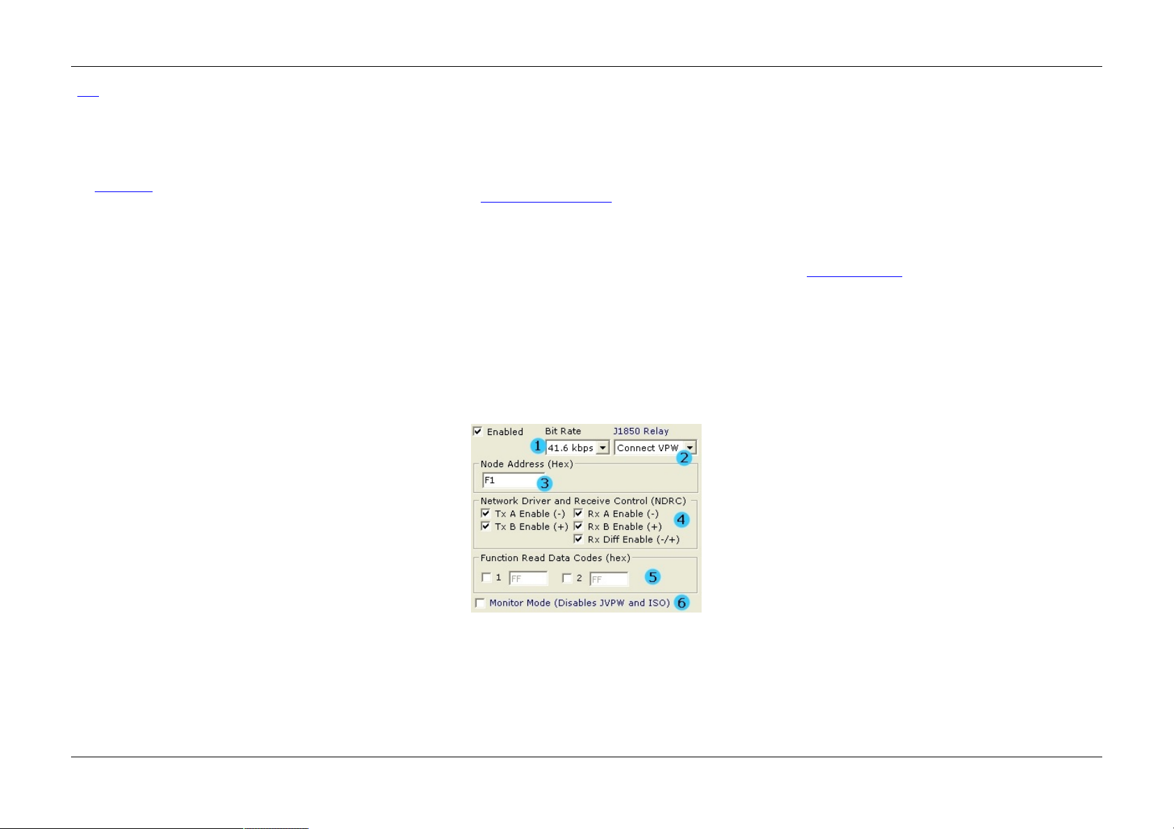
Firs t, you ca n set the bit rate of the SCP network (figure 1 : bubble 1). The standard network bit rate is 41.6 kbps. The higher speed 83.3 kbps is sometimes used on the network for special network operations. Special Monitor mode only supports the 41.6 kbps rate.
The OBD connector used in neoVI connects the J1850 VPW network to the J1850 + line. neoVI contains a relay the can switch the JPWM + si gnal on to that line instead of JVPW. This allows you to use one connector with both protocols. You can have neoVI default to
either connecting VPW (default) or PWM (Figure 1: bubble 2). You can control the relay at run time using a neoVI virtual network can message.
You can set the Node Address of the Ford SCP node. This is shown in the figure 1: bubble 3. This is used for setting the source id and is used when the LBCC generates In frame responses (IFRs). This address must be unique for each node on the SCP network.
Next, you can set the Network Driver and Receive Control Register (NDRC) of the LBCC. This is shown in figure 1 bubble 4. The NDRC is a register in the LBCC which allows you to transmit o r rece ive on p orti on s of the d ua l wire n etwork. Norm a lly, thes e
sh o uld a ll be che ck ed .
Th e LBC C a llo ws yo u to o pti on a lly han dl e two fun ctio n re a d d a ta me s sa ge para m e te rs. The s e are s et up in fig ure 1 : b ub bl e 5. I f yo u wan t to ha ndle a fu nction re ad d ata me ss a ge , check the num b e r 1 o r 2 and e nte r th e
fu nctio n co de . Th e se s e ttin gs a re e nt ere d in Lo o k up Ta ble 2 of th e LB CC de vice . You ca n se t the a ctual da ta f or the fun ctio n code with the "LBCC S et FR e ad d a ta " n e oV I virtua l ne twork co m m a nd .
You ca n setup th e LBCC loo k up ta ble 1 (fig ure 2) . Loo k up ta ble 1 con tro ls what fun ctio na l me ss a ge s the LB CC sho ul d receive . Yo u can have up to 31 e nt ries in th is ta ble . In figu re 2, we s etup the LBCC to re cei ve thre e
fu nctio n al m e ss a ge s in cludin g 0x 1 E, 0 x F1, a nd 0 x 22 . Bl an k s pa ce s in th e ta ble are i gn ore d .
Special Monitor mode allows you to monitor all traffic on the SCP network. To enable this node click the check box in figure 1 bubble 6. This enables special firmware in neoVI that monitors and decodes the raw SCP waveform. When this is done, both J1850 VPW and
ISO/KW2k protocols are disabled. You can still use the Ford LBCC channel. All monitor mode messages come across on the J1850VPW network.
Node Address - Th e SCP Nod e a d dre ss is us ed fo r thre e pu rpo ses . First, th e n o de a dd ress is th e third byte of every trans m itte d me ss a ge (th e so urce a dd res s ). Ne xt, the a dd re ss is u se d f or n od e ad d res s ackn o wled ge m e nt.
Fin al ly, it is us e d to dete rm in e which phys ica lly ad d res se d SC P m ess a ge s s ho ul d be re ce ive d.
Tx Driver Enable -Thes e two bits e n ab le n e twork d rive rs A (b us -) an d b (b us +) . W h e n s e t, ea ch b it will en a ble the co rre sp ond ing o u tpu t p in d rive r. W he n the bit is cle a r th e pi n is tristated .
Rx Enable Bits - T he s e th ree b its co ntrol the inp uts into the L BC C bit d eco d er. Th e re ceivers a re e na b le d when th e b its a re a "1 ". Dis a ble d re ceivers f orce a " stuck a ctive " con d itio n to the bit deco d ers .
Figure 1 - The LBCC Node A ddress, NDRC, and Function Re ad Da ta Code s Setup
Intrepid Hardware Help J1850 PWM (Ford PWM)
29 / 71

Figure 2 - LBCC Lookup Table 1 set up.
neo VI Doc ument ation - (C) Copyright 2000-2019 Intre pid Control Syst ems, Inc.
La st Up d ate: Thursday, July 09, 2009
Intrepid Hardware Help J1850 PWM (Ford PWM)
30 / 71

J1708 - neoV I
Ma in
A pplies to
neoV I Blue, and neoVI Yellow
Th e re are no s etting s fo r th is n etwork.
neo VI Doc ument ation - (C) Copyright 2000-2019 Intre pid Control Syst ems, Inc.
La st Up d ate: Wednes day, March 11, 2009
Intrepid Hardware Help J1708
31 / 71

UA RT/ISO9141/KW 2K/LIN - neoVI
Ma in
A pplies to
neoV I Blue, neoVI Red, neoVI FIRE , and neoV I Ye llow
Th e n e oVI su ppo rts a U AR T /ISO 91 41 /Ke yword 2 00 0/ LI N n etwork . T his ne twork i s ba s ica lly a U AR T/ SC I u nit with a h ard ware leve l s hif te r (Fig ure 1 ). T he re a re m any va ria nt s of a UA RT ne twork s chem es which ca n b e m o nitore d
with th is n etwork.
As s ho wn in fi gu re 1 , the ne twork ha s a pu ll u p vo lta ge fo r the K an d L li ne of V BATT. I n ne o VI Blue , the pu ll up res is to r ca n a ls o b e ch ang ed . Pl ea s e s e e th e Ha rd ware Se ttin gs topic for m o re in fo rm a tio n o n ch an gi ng the s e
ite m s. P le ase n ote tha t the f a ctory de fa u lt p u ll u p vo lta ge is VBATT with a p ull up re s istor of 510 o hm s .
Figure 1 - neoVI implem ent s a hardware lev el shifte r for each K and L line.
As sho wn in fi gu re 2, th ere are m any se tti ng s you ca n a dju st fo r yo ur UART n e twork. T h es e o ptions a re di scu ss e d in the fo llo wing to pics :
Ti m ing /Ba u d Rate , In itia li za tio n, a nd Erro r C he ck in g.
Intrepid Hardware Help UART/ISO9141/KW2K/LIN
32 / 71

Figure 2 - There are many sett ings for UA RT Communications.
neo VI Doc ument ation - (C) Copyright 2000-2019 Intre pid Control Syst ems, Inc.
La st Up d ate: Thursday, July 09, 2009
Intrepid Hardware Help UART/ISO9141/KW2K/LIN
33 / 71

UA RT Timing - neoVI
Ma in
A pplies to
neoV I Blue, neoVI Red, neoVI FIRE , and neoV I Ye llow
Th e U AR T ne twork s up ports s of tware p rog ram ma bl e tim in g pa ra m e ters . Th e se i nclu de the b a ud ra te a nd ti m e de li m ite rs as d e scrib e d in the ISO 9141/Keyword 2 00 0 sp e cs.
Firs t, you ca n se tu p a bau d rate . I ntre pid Ha rdware Ex p lo rer pro vid es y ou with m any com m o n UART s p ee d s pre s en t i n Vehi cle Network s to ch oo s e fro m .
In n orm al U AR T o pe ra tio ns timi ng d e lim ite rs spe cify how m e ss a gin g ta k es p la ce . Th e se s e ttin gs a re s ho wn in F igu re 2 be low. Th e s e ttings a re e xp la in e d in table 1 b e lo w.
Figure 1 - Yo u can setup a baud rate for UART communicat ions.
Figure 2 - The timing specifications used in ISO com municat ions for m essa ge delineat ion.
Table 1 - Descr iptions of t iming param ete rs in ISO/UA RT
Timing Param ete r P ara met er Name D escription
Rx In ne r F ram e Sp a cing Rece ive In ter-fra m e Se para tio n
ne o VI dete rm in e s whe n a m e ssa ge en ds us ing th is p aram e te r. If n o da ta b yte h a s be e n
rece ive d withi n t his p e riod the e n d of m e ss a ge is sign al ed .
Tx In ne r Fram e Spa cing Tran sm it In te r-fra m e Se p ara tio n T his i s the d e la y th e tra ns m itte r will wait b e twee n two m e s sa ge tran s m iss io ns .
Tx In ter byte Sp acing Tran sm it In te r-b yte Se p ara tio n Th is is th e d el ay th at ne o VI use s betwee n e ach tra nsm it byte.
The Message Termination section allows you to choose how frames are spaced. Select Inner Frame Time for ISO9141 or Keyword 2000 networks. For GME CIM-SCL networks select GME CIM-SCL.
Figure 3 - If working with a GME CIM-SCL network select GME CIM-SCL.
neo VI Doc ument ation - (C) Copyright 2000-2019 Intre pid Control Syst ems, Inc.
La st Up d ate: Monday, May 24, 2010
Intrepid Hardware Help UART Timing
34 / 71
UA RT Initialization Wave form s - neoV I
Ma in
A pplies to
neoV I Blue, neoVI Red, neoVI FIRE , and neoV I Ye llow
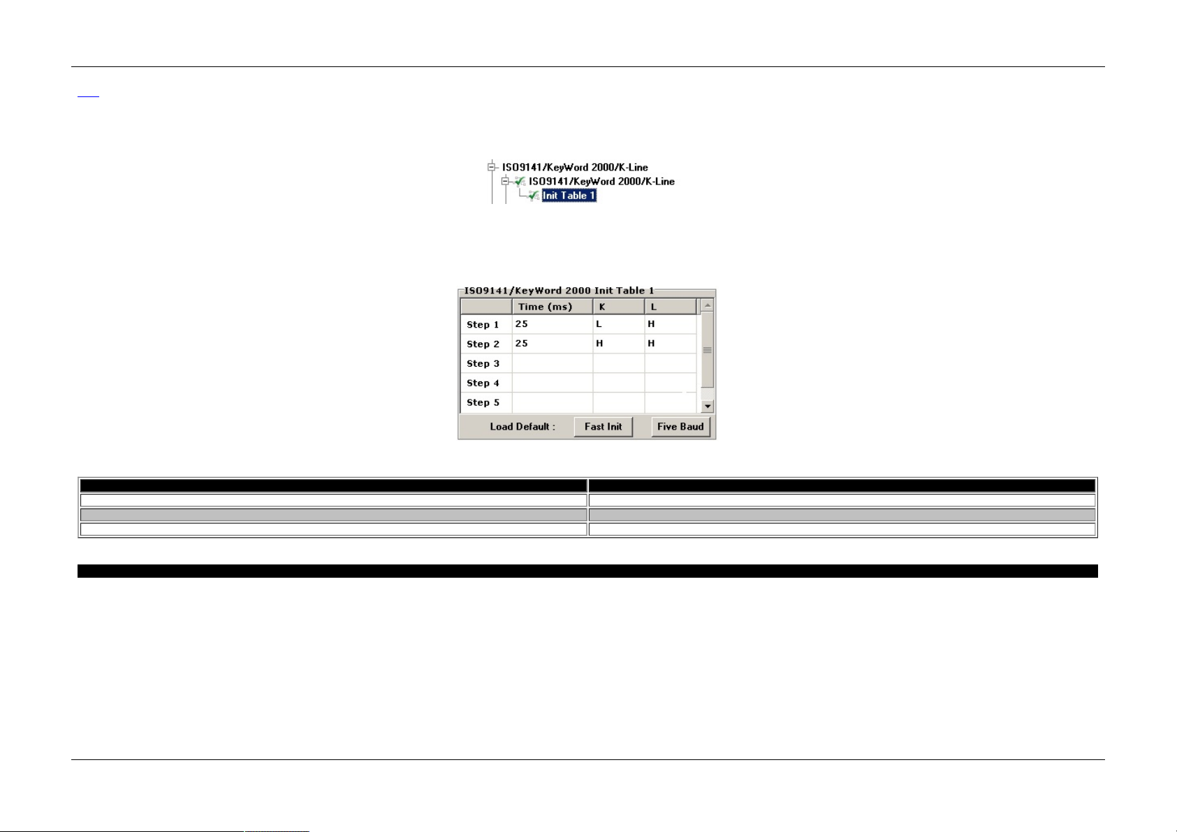
So m e U AR T s ta nd ard s s uch as Ke yword 2 00 0 a nd ISO 914 1 requ ire yo u to in itia liz e an ECU be fo re a tte m p tin g to se nd m e ss a ge s to it. U su a lly th is in itia li za tio n in vo lve s s ig na ling o n e ithe r o r bo th of th e K a n d L li ne . Yo u ca n
se le ct the initializa tio n fro m th e I nit ta ble se ctio n o f th e I SO 91 41 /Ke yW ord 2 00 0/ K-Line se ctio n o f the h ard ware Ex pl ore r ( fig ure 1 )
Figure 1 - Init table opt ion in hardware explorer.
You can ca u se a in itia li za tio n to occu r o n th e n etwork by clickin g th e I ni t co lu m n in Ve hicle Sp y or setting the init f la g in th e s ta tus bit-fi eld in th e m ess a ge yo u se n d via the DLL . Th e m essa ge ca n ha ve no da ta b yte s ( fo r f ive
ba u d initia liz ati on f or ex a m ple).
ne o VI sup po rts the sta n da rd in itia liz a tio ns li ke Fast I nit and Five Ba ud . Als o, neo VI a ls o offe rs a custo m in itiali za tio n beca use th e re ha s b ee n a va rie ty of in itia liza tio n im p lemen ta tio ns .
Fo r cus to m in itia li za tio ns y ou ca n ha ve a 16 step wav ef orm . Th is is d e fin ed in the cu stom initi al iza tio n ta bl e in hard ware e xp lo re r. Ea ch s te p ca n las t up to 3 2. 76 7 se cond s an d ca n con trol both th e K an d the L lin e .
Figure 2 - Yo u can select the init type from the dro p down list in neoVI explorer.
Table 1 - Initialization opt ions in Vehicle Spy
Initializat ion De scription
Fas t I nit A 2 5 m s lo w o n the K lin e f oll owed b y a 25 m s h igh f ol lowed b y the s ta rt co m m un ica tio n m es s ag e
Five B au d Addre ss 0 x 55 tra ns m itte d a t 5 Ba u d (0 .12 5 m s / bit)
Cus tom Wa ve fo rm is u se r d e fin e d by a si xtee n e ntry ta ble
neo VI Doc ument ation - (C) Copyright 2000-2019 Intre pid Control Syst ems, Inc.
La st Up d ate: Saturday, March 21, 2009
Intrepid Hardware Help Initialization Waveforms
35 / 71

UA RT Error Checking - neoVI
Ma in
A pplies to
neoV I Blue, neoVI Red, neoVI FIRE , and neoV I Ye llow
Th e I SO 914 1 and Keyword 20 00 p rotoco ls u s e a che cksu m f ie ld to pro te ct the da ta th a t is tra ns m itte d . n e oV I a llo ws yo u to di sa b le th e a u tom atic a dd itio n o f th is ch eck s um to tra ns m itte d m essa ge s a nd the che ck in g o f it on
the rece pt ion o f m e ss a ge s . T hi s m aybe u se f ul fo r a U AR T pro to col th at do e sn 't us e th e che ck su m o r ca lcu la tes it d iff eren tly. A p arity s etting i s al so a va ila b le if yo ur ne twork re qu ire s thi s.
Figure 1 - The standard check sum f or ISO comm unications ca n be disabled. Parity can also be adde d if neede d.
neo VI Doc ument ation - (C) Copyright 2000-2019 Intre pid Control Syst ems, Inc.
La st Up d ate: Saturday, March 21, 2009
Intrepid Hardware Help Error Checking
36 / 71

LIN : Local Interconnect Network - neo VI
Ma in
A pplies to
neoV I Blue, neoVI Red, neoVI FIRE , and neoV I Ye llow
ne o VI sup po rts commun ication o n LI N (Lo cal In te rcon nect Network ).
O nce de te ctin g a pro pe r Syn c Brea k an d Sync fie ld , th e n eo VI will wait fo r th e Ms g I de ntifie r fie ld . T he m e ss a ge rece p tio n will be g in wi th th e M sg ID f ie ld. Th e n e oV I will rece ive th e e ntire m e s sa g e a ccord in g to the LI N s pec.
Afte r re ce ivin g the m es s ag e e rror fre e, th e neo VI will s e nd th e re ce ive d m es s ag e to th e h os t s ta rtin g with th e Ms g ID fi el d.
If th ere are a n y e rrors n eoVI will rep o rt th e e rrors b ack to the h o st. Ta ble 1 be lo w lis ts the e rro rs che ck ed f or by the ne o VI de vice.
ne o VI sup po rts a cting a s a m onitor, m aste r, a nd sla ve .
Ena bl ing LI N is don e in th e Ha rd ware Explo re r. F or n eo VI Blu e L IN is en a bl ed un der th e ISO 91 41 /KWo rd 2K/U AR T/ LI N o p tio ns . Se t the Mod e t o "LIN M od e " a nd the "R x Tran s ceiver" to LI N. Als o m a k e s ure th e b a ud rate is
corre ct f or you r n e twork (Fi gu re 1) .
Figure 1 -LIN mo de is ente red via the neoVI Explore r.
To Ena ble LI N o n a ne o VI FI RE, ne oVI R ed , an d ne oVI Ye llo w is do ne in Ha rdware Exp lo rer by Se le cting the ch an n el un d er ne twork En ab le s a nd th e n se ttin g the pro pe r b a ud ra te for tha t L IN ch a nn e l (Fig ure 2 )
Figure 2 -LIN mo de is enabled v ia the neoVI 3G Explorer.
Figure 3 - A LIN Message
Table 1 - Errors det ecte d in LIN mode.
Error De scription
ISO_L IN_SY NC_BR K_ER R Th e Syn c Bre a k d id no t ha ve a ll ze ro 's
ISO_L IN_SY NC_LEN_ER R Th e Syn c Bre a k d id no t ha ve a t l ea s t 9 z ero 's
ISO_L IN_SY NC_W AV_ER R Th e Syn c Wa ve form re ce ive d a fte r a va li d Sync Bre ak was no t 0 x55
ISO_L IN_MSG_ID_PR T Y Th e M SG I D fie ld was n ot va lid b a se d o n the M SG ID p arity b its
neo VI Doc ument ation - (C) Copyright 2000-2019 Intre pid Control Syst ems, Inc.
La st Up d ate: Monday, June 01, 2009
Intrepid Hardware Help Local Interconnect Network (LIN)
37 / 71

LIN Slave Table - neoVI
Ma in
A pplies to
neoV I Blue, neoVI Red, neoVI FIRE , and neoV I Ye llow
LI N Sl ave m e ss a ge s se nt to th e ha rdware a re s tore d in th e h ardware 's inte rna l s la ve ta b le un til it is req ue s te d by a m as te r m essa ge re qu e st. Da ta in th e inte rna l Sla ve Ta ble ca n up d ated b y res e nd in g th e s la ve mes sag e i n
your s o ftware a p pli cati on . W he n a m a st er req ue s t is re ce ive d by th e ha rd ware, th e la te st da ta f or tha t I D in the LI N Sla ve ta b le will b e s ent.
neo VI Doc ument ation - (C) Copyright 2000-2019 Intre pid Control Syst ems, Inc.
La st Up d ate: Monday, June 01, 2009
Intrepid Hardware Help LIN Slave Table
38 / 71

Hardware F eat ures - neoV I
Ma in
A pplies to
neoV I Blue, neoVI Red, neoVI FIRE , neoVI Ye llow, and ValueCA N
Be cau se of th e diffe ren ce s in ha rd ware, th es e s e ctions a re sp lit up b e twee n the dif fe rent ha rdware type s .
- neoVI Blue
- neoVI RED \ neoVI FIRE
- neoVI Yellow
- ValueCAN3
neo VI Doc ument ation - (C) Copyright 2000-2019 Intre pid Control Syst ems, Inc.
La st Up d ate: Thursday, July 09, 2009
Intrepid Hardware Help Hardware Features
39 / 71

Hardware F eat ures
Ma in
A pplies to
neoV I Blue
Th e n e oVI d ev ice h a s m a ny co nf ig ura ble fe ature s which are no t in -ve h icle ne twork s. T h is s e ction de tails the m . T his section also con ta ins the neo VI th e ory o f ope ra tio n. T he hard ware fea tures dis cus s ed in th is se ctio n inclu de
the fo llo wing:
1) neo VI LED
2) Ge n era l Pu rpo s e IO
3) DAQ Pa ce r C lo ck
4) Sp e cifica tio ns
5) Ha rd ware Se ttin gs
neo VI Doc ument ation - (C) Copyright 2000-2019 Intre pid Control Syst ems, Inc.
La st Up d ate: Thursday, July 09, 2009
Intrepid Hardware Help neoVI Blue
40 / 71
Theory of Oper ation - neoV I
Ma in
A pplies to
neoV I Blue
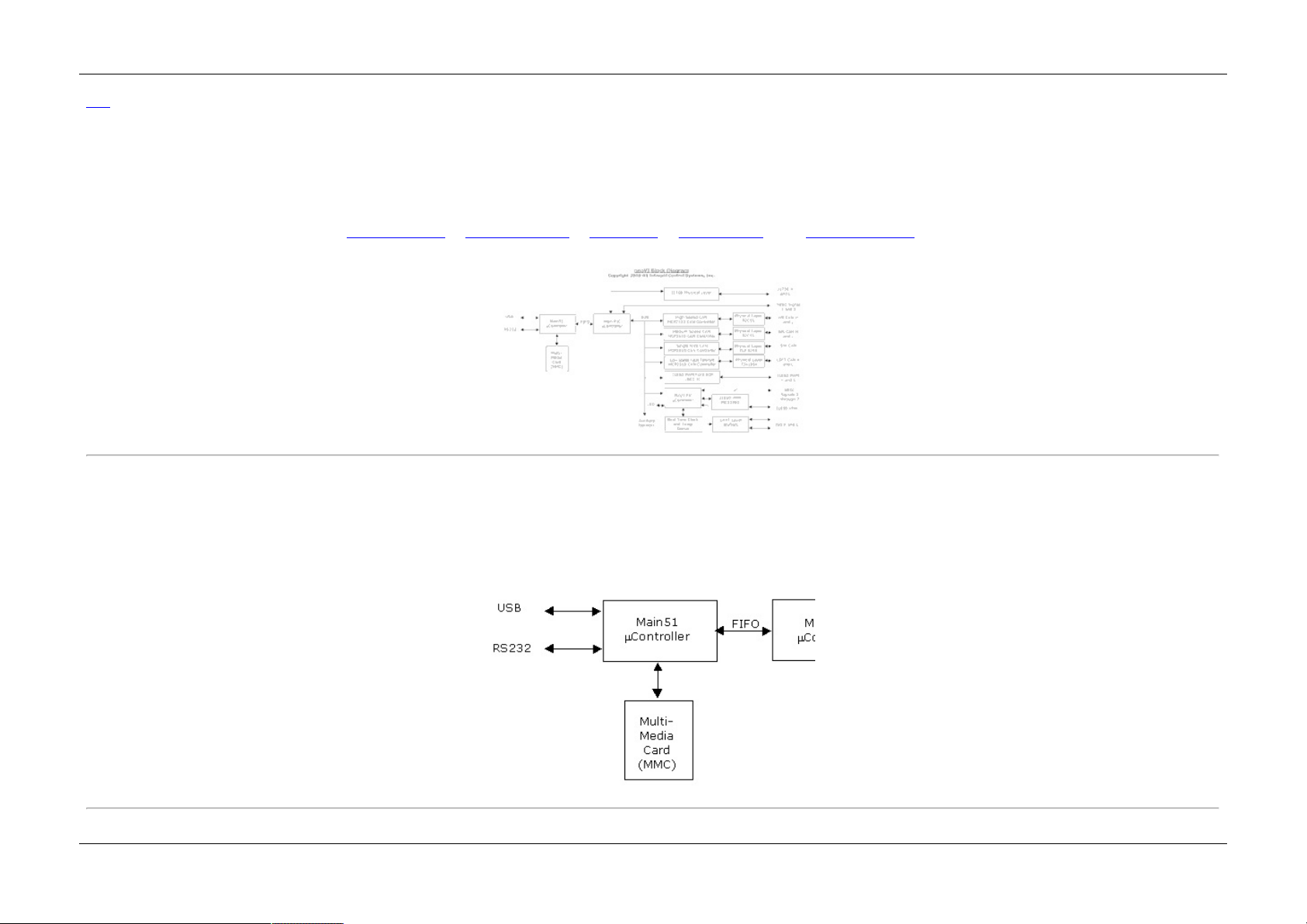
Th is s ection d e ta ils th e the o ry-o f- op e ration o f the ne o VI de vice. A b lo ck d ia gra m o f the de vice is sh own in fig ure 1 b e lo w.
Th e n eo VI d e vice co ns is ts of th ree ind e pe n de n t µ Co n trollers which h a ve a to ta l o f 20 M IP S ( m illi on s o f i ns tructio n s pe r s e con d) o f pro ce ss ing po wer. T his p ro ces sing p ower can re a d m ess ag e s fro m 9 in de p e nd ent ne twork s. Aft er
rea d ing the m e s sa g es th e n eo VI ca n do on e o r a ll of th e fo llo wing th ing s : 1 ) se nd the m to the P C via RS 23 2 or USB, 2 ) p ro ces s the m es s ag e , o r 3 ) sto re th e m e ss a ge i n on bo a rd sto ra ge .
Th e fun ctio na li ty of the ne o VI i s b as e d o n its firm ware . All th ree o f th e µ Co n trollers in th e ne o VI d e vice ha ve fie ld up gra dea b le f irm ware . Th is mea n s th e neo VI de vice ca n be u pd a ted with ne w f un ctio na lity a t a ny tim e i n th e
fu ture .
Th e fo ll owing to p ics e xp la in th e diag ra m fu rthe r: 1 ) Ma in 5 1 µ C on tro lle r, 2 ) Ma in P IC µC ontro lle r, 3 ) CAN Network s , 4 ) LBC C P rot oco l I C , an d 5) I SO /J P IC µ C on trolle r s ecti on .
Figure 1 - the neoVI block diagram (click for large r image)
Main 51 µController
Th e Ma in 51 µC o ntro lle r (f igu re 2) is resp on s ibl e for co lle ctin g me ss a ge s fro m the Main P IC µ Co n troller and proce ss in g them. Norm a lly, whe n n e oVI is us e d as a P C inte rfa ce this mea n s s e nd ing th em to th e PC via USB or
RS23 2. It a ls o cou ld s tore the m e s sa g es o n it's M MC (m ultim edia ca rd s tora g e de vice) . I t co ul d al so p roces s the m es s ag e s an d do so m e thi ng s uch a s trans m it a re s po n se o r ch ang e a gen e ral pu rpos e I O bi t.
Th e RS232 p ort is cap ab le of 11 5.2 kb , 57. 6 kb , 38 .4 k b, 28 .8 kb, 19.2 kb , 960 0 bp s, and 480 0 bp s ba u d rate s . It inclu de s RS2 32 contro l line s for ha rdware hand sh a ki ng (RT S/C TS) an d DT R a cting as a DCE (Da ta
Com m u nica tio n Equip m e nt) d ev ice.
Th e U SB p o rt s up po rts U SB 1 .1 fu ll sp e e d 12 Me g a -Bits p e r s eco n d. The d e vice is s o ftware p rog ra mmab le to u s e eithe r B ulk on ly or I s och ron o us in /b ul k out tran sf e rs.
Th e n eo VI d e vice d ef a ults to 56 k Ba ud R S2 32 co m m un ica tio n on p o wer up. Th e co m m un ica tio n can th e n be ch a ng ed b y the h o st so ftware by se n din g co m m an ds o n U SB o r R S2 32 .
Figure 2 - The Main 51 µController
Main PIC µController
Intrepid Hardware Help Theory of Operation
41 / 71

Th e M ain P I C µC o ntroller is the he a rt o f the Vehicle ne twork fu nction s . I ts job i s to rea d n etwork mes sa g e s fro m th e sp e cific su bs e ctio ns , tim e sta m p th em a nd s end th em to the M a in 51 µ Con trol le r.
Th e M ain PI C µCo ntroll er is directl y re sp o ns ib le fo r the M IS C 1 an d MI SC 2 s ig na ls , the J 17 08 p rotoco l, a nd co nf igu ra tio n of th e LBC C a n d CAN contro lle rs. As th e o wne r o f th e times ta m p clo ck, th e Ma in P I C ge n erate s th e tim e sta m p clo ck fo r the DAQ p ace r f un ctio na lity. It al so o wns the trigg e r s igna ls fo r J 17 08 , F ord SC P ( LBC C ), a nd a ll of th e C AN n etwork s .
Th e M ain P I C µC o ntroller is p rote cte d b y a in te rna l watchd og ti m er an d co ntro ls th e res e t line s fo r a ll o f th e o ther circuits .
Figure 3 - The Main PIC µController
CA N Networks
ne o VI ha s f ou r in de p e nd ent CAN ne twork s. T he CAN pro to col IC is the M C P2 51 0 IC fro m Mi croch ip Te chn olog y. Ea ch pro toco l chip , is conn ecte d to the a p pro pria te p h ysi cal la ye r fo r th a t C AN n e twork. Al l s ta tus a n d con trol s ign a ls
fo r e a ch p h ysical la ye r a re m ap p ed to inte rn al µC o nt roll er pin s . T hi s al lows com ple te so ftware con trol o f the C AN f un ctio na lity.
Figure 4 - The neoVI CA N Networks
LBCC Prot ocol IC
Th e LBC C pro to col is a pro to col I C fro m Vis te on which perf orm s the J18 50 PW M Fo rd SC P pro to col . It sup po rts a prog ra mmab le fu nction id tab le with 3 1 lo ca tio ns , a pro g ram m a b le ne twork ad d res s, and two pro gra m m a bl e
fu nctio n re ad d a ta re gis te rs.
Figure 5- The neoV I LBCC interf ace
ISO /J PI C µController Sec tion
Th e I SO /J P IC µC o ntro lle r m ain fun ctiona lity is to ge nera te th e J 18 50 VP W an d I SO /U AR T pro to cols. O the r res pon si bil itie s in clud e th e f ollowing: 1) L ED C o nt rol, 2 ) Re a l-Ti m e C lo ck In te rfa cin g, 3) O n-bo a rd Te m pe ra ture S en s or
Intrepid Hardware Help Theory of Operation
42 / 71
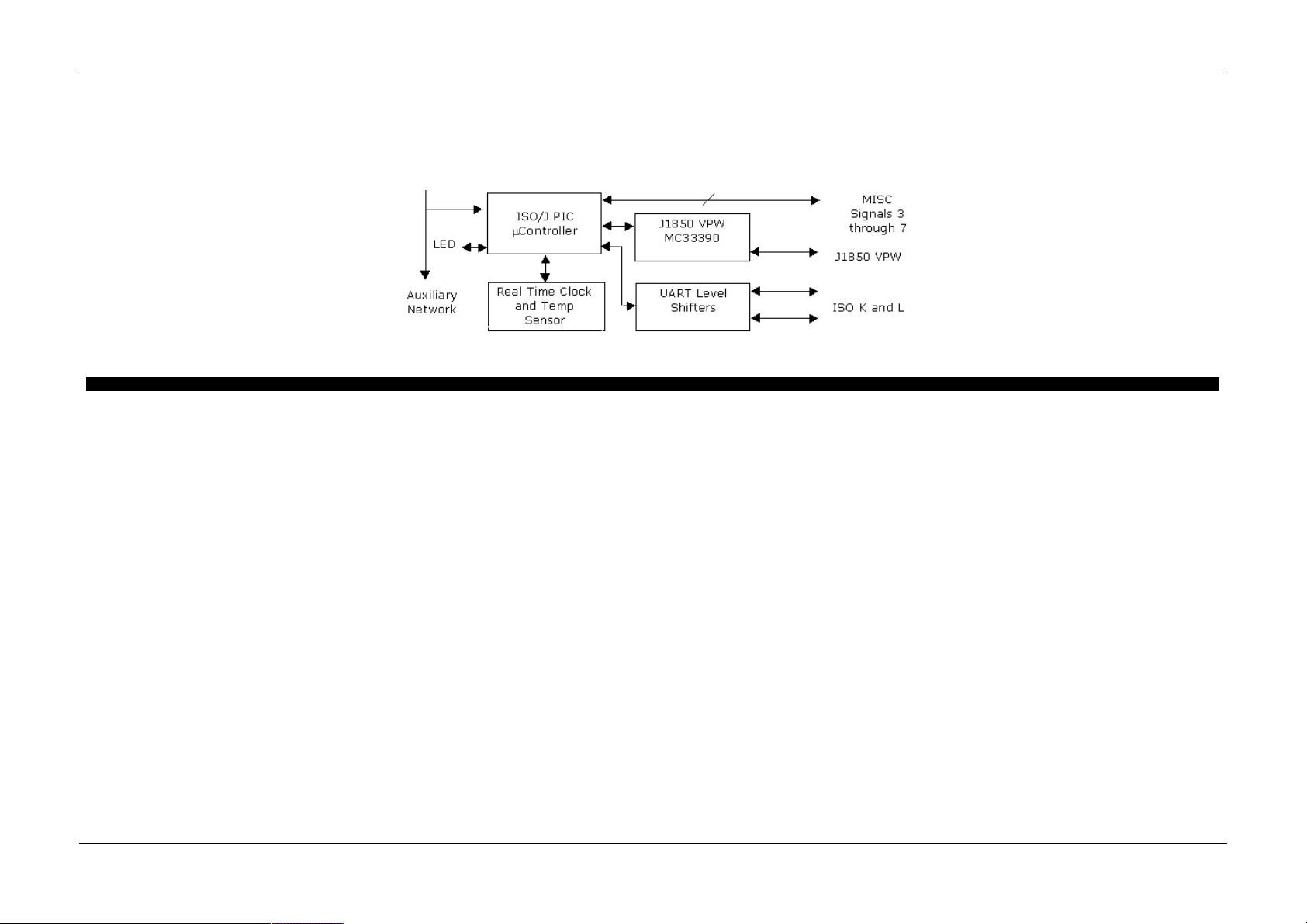
In te rfa cing , an d 4) M ISC sig n al s 3 thro ug h 7.
Th e J 18 50 V PW so ftware is s o ftware co n troll ed pe rip he ra l ba s ed VP W g ene rat ion . T his m ea n s th at th e ISO /J P IC µC o ntro lle r us e s a timing p e riph e ral to ge n era te an d re cei ve va ria b le p ul se width (VPW ) wave fo rm s . Th is a llo ws
the ne o VI d ev ice to cre a te f au lts a n d ana lyz e VP W wavef orms tha t wou ld n o t b e p os s ible with ot he r p rotoco l IC s . It also al lows s up po rt of d iff eren t i n-frame resp on s es which cau se inco m p atibilitie s b e twee n J1 85 0 VP W p roto co l
IC s .
Th e I SO /U AR T se ctio n is ve ry f le x ibl e. T he K a nd L lin e s ha ve s o ftware co ntro lle d tra ns m it ena bl e lin es all owing m any di ffe re nt va ria nts o f UAR T o r ISO 91 41 co m m un ica tio ns in clu din g: T x o n L Rx o n K; T x a nd R x o n K; Tx o n K
an d L an d R x o n K.
Th e M ISC sig na ls co n tai n fo ur 1 0 bi t a na lo g in pu ts a nd o ne ex terna l wake -up in pu t.
Figure 6 - The ISO/J PI C µController Section
neo VI Doc ument ation - (C) Copyright 2000-2019 Intre pid Control Syst ems, Inc.
La st Up d ate: Thursday, July 09, 2009
Intrepid Hardware Help Theory of Operation
43 / 71

LED - neo VI
Ma in
A pplies to
neoV I Blue
Th e b eh a vio r o f the n e oVI LED i s pro gra m m a bl e. T h e LED can b e s etu p to a ctiva te o n ne twork a ctivity, d isp la y the s ta te o f a MI SC p in, o r cha n ge s ta te a ccordin g to a s cript. Yo u can s e tup th is b eh a vio r in th e ne o VI Ex pl ore r.
Th e LED O pe ra tin g Mo de se le ctio n (figu re 1 : b ub b le 1 ) s e ts the be ha vi or. T he LED se ttin gs are liste d in Ta b le 1 below.
Fo r setting s tha t cau se the L ED to fla sh the n eoVI p ro vides two add itio na l se tti ng s. T he f irst setti ng is th e flash typ e . Yo u ca n eithe r h av e the LED t urn gree n a nd th e n t urn o ff or fla s h gre e n an d res u m e red f la sh in g. The s e con d
se tting is th e fl as h du ra tio n. Th is is the time the g ree n e le m e nt is a ctive fo r e a ch fla s h.
Th e LED ca n also b e co ntro lle d th rou gh th e n eo VI D evice virtu al n etwork .
Figure 1 - How the neoV I LED works can be set in neoVI ex plorer.
Table 1 - The LED O perat ing Modes
LED Operat ing Mode De scription
Sta nd a rd Mo de
Th e s tand ard L ED s e tting. Th is s etting will cau s e the LED to tog g le b etwe en R e d a nd o ff e ve ry 104 m s. Yo u can
al so co ntrol the LED with scripts u si ng th is setti ng .
Dis pl ay MI SC 3 Dis pl ays the s ta te o f the M ISC3 p in . I t will dis p la y g ree n if th e pi n is on o th erwise it will b e o ff.
Dis pl ay MI SC 4 Dis pl ays the s ta te o f the M ISC4 p in . I t will dis p la y g ree n if th e pi n is on o th erwise it will b e o ff.
Dis pl ay MI SC 5 Dis pl ays the s ta te o f the M ISC5 p in . I t will dis p la y g ree n if th e pi n is on o th erwise it will b e o ff.
Dis pl ay MI SC 6 Dis pl ays the s ta te o f the M ISC6 p in . I t will dis p la y g ree n if th e pi n is on o th erwise it will b e o ff.
Dis pl ay MI SC 7 Dis pl ays the s ta te o f the M ISC7 p in . I t will dis p la y g ree n if th e pi n is on o th erwise it will b e o ff.
neo VI Doc ument ation - (C) Copyright 2000-2019 Intre pid Control Syst ems, Inc.
La st Up d ate: Wednes day, July 15, 2009
Intrepid Hardware Help LED
44 / 71

General Purpose IO
Ma in
A pplies to
neoV I Blue
Ov erview
ne o VI ha s s ix g e ne ral p urp os e 5 VD C IO pin s. T he s e a re la be le d a s MI SC s ig na ls o n the ne o VI con ne ctor. T he s e pi ns ca n be us ed f or con tro llin g or m on ito rin g ex te rna l de vices .
Basic Setup
Th e g en e ral p urp os e I O a re se tu p in the ne oVI ex p lo rer. T he ge n era l IO t ree n o de i s sh own in fig ure 1. O n the p a ne l you ca n setu p th e directio n , ty pe , an d in itia l sta te o f ea ch I O pi n.
Each M ISC sig na l ha s a d rop d own bo x ( fig ure 1 : b ub ble 1). I n thi s dro p do wn b ox yo u can s et if the MI SC p in is a n inp u t, o u tpu t initi ally o ff, or an o u tpu t initially o n.
Th e outp uts a re cap a ble of L ED drive thro ug h a curren t lim iting resis to r. The m a xim um curren t of a ll outp uts sho ul d not ex cee d 50 m A. Fo r pro te ctio n, ea ch IO pin h as a s eries 100 oh m re sisto r a nd a trans ie nt prote ctio n
de vice .
A nalog Input s
If s etup a s in pu t, MI SC p ins 3 t hro ug h 6 can b e s e tup a s a na lo g in pu ts . Yo u ca n se tu p ana lo g inpu ts via th e " Ana lo g Se ttin g" d rop do wn (fig ure 1 : b ub bl e 2) . T h e setti ng s a re : 1) no an a log inp uts, 2) a na lo g in put on M IS C 3,
an d 3) a nalog in puts o n MI SC 3 -6 .
W he n se tti ng u p MI SC 3 on ly, th e s am plin g rate will be on ce pe r m ill ise con d . If th e se tti ng is f or MI SC 3- 6, the sa m pl e rat e will b e e very fo ur m illi se co nd s.
General IO Re porting
You ca n s et up the g en e ral IO to be a uto m a tica lly repo rte d to the ho s t in ne o VI ex plo re r (fi gu re 2). Yo u can s e tup the gen e ral IO to be repo rte d a t a n in te rva l or bas e d on d ig ita l in pu ts chan gi ng (figu re 2 : bub bl e 1). T he
rep o rt will b e s ent to the h o st as a ne o VI De vice V irtua l Network m ess a ge .
W he n repo rting ba se d o n inte rva l is se le cte d yo u can s e le ct th e interva l fro m th e drop d own bo x s ho wn in b ub b le 2 in fi gu re 2. Yo u can s elect a n inte rva l fro m 1 to 125 m s.
If yo u se le cte d a re po rt b a se d o n di gita l cha n ge , you ca n s el ect bo th a n int erva l the inp uts a re te s te d (figu re 2 : b ubb le 2 ) a n d which d ig ita l i np uts to tes t (fig u re 2 : b ub b le 3). You ca n se le ct as m a ny a s are lis ted .
Th e re po rt b a se d o n digita l cha nge will "de- bo unce " the re a ding b y te s ting t he in p uts twice . Ea ch te st will o ccur a t on e -ha lf th e tim e in te rval.
Figure 1 - neoVI MISC pins can be setup as digita l outputs, digital inputs or analog inputs.
Intrepid Hardware Help General Purpose IO
45 / 71

Figure 2 - Yo u can have the neo VI de vice aut oma tically repo rt the state of MISC I O pins.
neo VI Doc ument ation - (C) Copyright 2000-2019 Intre pid Control Syst ems, Inc.
La st Up d ate: Tues day, J anuary 08, 2013
Intrepid Hardware Help General Purpose IO
46 / 71

DA Q Pacer Clock - neoVI
Ma in
A pplies to
neoV I Blue
Ov erview
Th e ne o VI de vi ce can ge ne ra te a clock (f ig ure 1) o n the MI SC 2 pin th at can b e use d to corre la te data co lle cte d with the neo VI devi ce with othe r d at a acqu is itio n eq u ipm ent tha t a cce pts a n ex te rna l clo ck . T he clo ck rate is
pro gram m a bl e be twee n 1 .25 Kh z a nd 2 .5 Mh z (See tab le 1 for f requ en cie s).
Th e n eo VI d e vice s tim e sta m p s the ex a ct s ta rt tim e o f the p u lse s . Th is st art tim e sta m p p rovi de s a m a rk er to com pare da ta fro m the DAQ boa rd a nd th e ne oVI.
How to use it
Th e fo ll owing list of s te ps s ho ws h o w to us e this fe a ture :
Step 1 : W ire th e MISC 2 s ig na l to the DAQ ca rd ex te rnal clo ck in pu t
Step 2 : S etup th e MI SC 2 Si gn al a s a digital o utp ut in n eo VI e x pl ore r
Step 3 : S tart Mo n ito ring th e network
Step 4 : Sta rt th e DAQ Card Da ta A cqu isitio n fo r a n ex terna l clock with th e de s ire d nu m be r o f sa m p le s
Step 5 : S en d th e Sta rt DA Q ne o VI De vice Virtual Network C om m an d to s tart the clock. ne o VI will s e nd a n e oVI De vice Ne twork m e ss a ge tim e-st am ped whe n the DAQ C lo ck was s ta rted.
Step 6 : R e co rd ne twork m e ss a ge s fro m the n eoVI u ntil the DAQ ca rd h a s acqu ired the p rop e r n um b er of s a m ple s
Step 7 : A fte r th e DAQ Ca rd com ple tes its sca n , a s se m b le th e DAQ card d ata an d ne oVI m e ss age b uf fe r in to on e buff e r us in g the sta rt ti m es ta m p. An a lyze, d isp la y o r s to re yo ur res ults.
Step 8 : S en d th e Sto p DAQ n e oVI De vice Vi rtua l Ne twork C o m m an d to s top t he D AQ C lo ck.
Figure 1 - neoVI generat es a pulse at a frequency which is time corre lated with the neoVI timest amp.
Table 1 - Sampling Frequency f or the DA Q P acer
neoV I Virtua l Network Comm and By te 1 Set ting Samp le Freque ncy
0 2.00 0 K Hz
1 8.00 0 K Hz
2 32 .0 00 KHz
3 40 .0 00 KHz
4 80 .0 00 KHz
5 16 0. 00 0 KHz
6 40 0. 00 0 KHz
7 80 0. 00 0 KHz
8 1.60 0 M Hz
9 4.00 0 M Hz
neo VI Doc ument ation - (C) Copyright 2000-2019 Intre pid Control Syst ems, Inc.
La st Up d ate: Thursday, July 09, 2009
Intrepid Hardware Help DAQ Pacer Clock
47 / 71

Specif ications
Ma in
A pplies to
neoV I Blue
De vice
* Po wer C o ns u m ptio n (typical) : 15 0m A @ 1 4.4 V DC
* Sle e p Mo de Po wer C o ns ump tio n (ty pica l) : 3m A @ 1 4.4 VDC
* Po wer S up pl y: v eh icle co m p ati ble 5.5 -2 0. 0 VDC
* Ph ys ical Di m en sion s : 12 0 x 70 x 2 5 m m ( 4. 8 " x 2.8 " x 1 .0" )
* We igh t: 1 13 g ( 4 oz )
* Non U SB Te m p era tu re R an ge : -4 0 t o 85 C
* USB Te m pe ra ture R a ng e : 0 t o 70 C
* Vehi cle C on necto r : 2 5 P in m ale D- SU B
* Sta nd ard P C /H os t Co nne cto rs: US B d owns tre am , RS23 2 9P IN D-S UB Fe m al e
* RS 23 2 po rt ca pa b le o f 11 5.2 k b , 5 7.6 kb , 38 .4 k b, 2 8.8 k b , 1 9. 2 kb , 96 00 b ps , an d 48 00 b ps b a ud ra te s. C o ntro l l ine s in clude h a rdware h an d sh aking (R T S/C T S) a nd DT R a ctin g as a DC E (D ata Co m m unica tio n Equ ip m en t)
de vice .
* Wa rran ty: On e ye a r limite d warran ty
* Firm ware : F ie ld up g rad e ab le d e sign (f la sh EEP ROM )
* On b o ard P ro ces sing : 20 MIP S R ISC bas e d m ulti -co ntro lle r d e sign
* Exp a ns io n: I nte rna l 5M hz SP I in te rfa ce a nd Ex te rna l D e vice T im e sta m p Syn chro niza tio n
* Bico lo r us e r notifica tio n LED (re d- gre e n) is u se r co nfig ura ble o r can ch a ng e o n ne twork a ctivity, trigg e r o r I O pi n.
* Ge ne ra l P urp o se I O : Se ven I O co nf ig ura bl e a s inp ut o r o utp ut. Fo u r con fi gu rab le a s 1 0 bit ana lo g inp u ts. O ne con fig ura b le fo r e x te rna l wake u p. ISO K an d L Lin es a va ila b le a s gen e ral pu rpo s e o utp uts. K L ine ava il ab le i s
ge n era l pu rpo s e inp u t.
* Ge ne ra l P urp o se I O ra te re po rt i nte rva l 1 -1 00 m s o r ba s e d on d ig ita l ch an g e. An a log i np ut sa m p lin g rate is 1 m s pe r ch ann el .
* On b o ard 9 -b it I C te m p era tu re se n so r with a ra ng e o f - 55 to 1 25 C ( -6 7 t o 25 7 F) .
* On b o ard n on-v olati le stora g e: 3 2KBy te EEPR O M a nd M MC ( Mu ltim e d ia C ard C a rd) s lo t fo r u p to 6 4M byte s o f on b o ard s to rag e .
* EMI Sh ie lded En closu re
* Emu la tio n o f G en e ral Mo to rs VSI I nte rfa ce vi a R S23 2
Networks - General
* Tim e s ta m ping to a ccura cy o f 10 0u S on C AN n e tworks , J1 70 8 ne twork , a n d Fo rd S CP ne twork . 2 50 µ s on C la s s 2 / J 18 50 VP W a n d ISO /KW2 K. T im e sta m p ro llo ve r is g rea te r th a n 1 yea r.
* Sim ulta ne o us o pe ra tio ns o n a ll ne twork s with a g gre ga te b a nd width p erf orm ance o f 2 m eg a b aud o ve r USB.
* Tran sm it m es s ag e d oub le -b uffe ring o n a ll n e twork s allows ba ck to b a ck m e ss a ge tra n sm is s ion.
* Mu ltip le h ard ware trig ge rs a llo w bit-wise filte r s pe cif icat ion s o n en tire m ess a ge ( firs t 1 2 bytes f or block ty pe m ess a ge s )
* Ge ne ra tio n of s can clo ck with corre la te d sta rt m essa ge tim e sta m p for s yn chro ni za tio n of e x te rna l da ta a cqu is itio n e qu ip m en t
* De vice wak e u p on n e twork a ctivity on a n y n etwork .
High Speed CA N
* ISO 11898 Du al W ire C AN P h ysi cal La ye r (82 C2 51 )
* CA N 2. 0B acti ve
* MC P 25 10 C AN co ntro lle r with su pp o rt fo r loo p -back a n d lis te n- only ope ration.
* Op tim ize d Rx an d Tx circuitry
* Up to 1 M -Bit sof tware se le cta b le bau d rate
* Graph ical Bit T im e /Ba ud R ate C al cula to r
Medium Spee d CAN
* ISO 11898 Du al W ire C AN P h ysi cal La ye r (82 C2 51 )
* CA N 2. 0B acti ve
* MC P 25 10 C AN co ntro lle r with su pp o rt fo r loo p -back a n d lis te n- only ope ration.
* Up to 1 M -Bit sof tware se le cta b le bau d rate
* Graph ical Bit T im e /Ba ud R ate C al cula to r
Low Speed Fault Tolerant CAN
* ISO 11519 Lo w Spee d Fau lt Tole ran t C AN Ph ys ical La ye r ( TJ A1054)
* CA N 2. 0B acti ve
* MC P 25 10 C AN co ntro lle r with su pp o rt fo r loo p -back a n d lis te n- only ope ration.
* Software s el ectab le b a ud ra te /b it timing u p to lim itatio n s of p hys ica l l ayer.
* Graph ical Bit T im e /Ba ud R ate C al cula to r
Single Wire CA N
* Sin gle Wi re CA N ph ys ica l la ye r G MW 30 89/ SAE J 24 11 ( TL E6255 )
* CA N 2. 0B acti ve
* MC P 25 10 C AN co ntro lle r with su pp o rt fo r loo p -back a n d lis te n- only ope ration.
* Hig h Sp ee d M od e , H ig h Spe e d Te st Too l Mo de , an d High Volt ag e Wa k e up s up port
Intrepid Hardware Help Specifications
48 / 71

* Software s el ectab le b a ud ra te /b it timing u p to lim itatio n s of p hys ica l l ayer.
* Graph ical Bit T im e /Ba ud R ate C al cula to r
GM Class 2/ SAE J1850 VPW
* VPW Phys ica l L ay er cap a ble of T x a nd R x o pe ra tio ns i n hig h sp e ed mod e s (MC 3 33 90 )
* Software co ntro lle d p eriph eral ba s ed V PW ge ne ra tio n
* Software m o di fia ble bit tim ing a ccep ta nce p a ram ete rs
* Software m o di fia ble bit tim ing ge nera tio n pa ra m e ters
* Trigg e r gen e rati on b ase d o n ne twork e rror or l os t a rb itra tio n eve nt
* Bad CR C g e ne ra tio n
* 4x h ig h sp e ed m ode ( lim ited s im u lta ne o us o pera tio ns a t 41 .6 k-b its )
* Blo ck trans fe r m o de
* Brea k g e ne ra tio n
* Bad Me ss a ge ge ne ra tio n cap a bl e
UA RT/ISO9141/Key word 2000 (ISO14230)
* K a nd L li ne s im p le m en te d
* UAR T Ba s ed sta te m a chi ne
* In itia liz a tio n wave fo rm s inclu d ing Fa st In it, Five Ba ud , C AR B an d C us to m
* Pro gram m a bl e tim in g pa ra m e ters i nclu di ng in te r-b yte , T X inte r-f ram e, RX in ter-fra m e a nd in itia li za tio n wave fo rm s (0 .5 m s res o lution)
* Software s el ectab le b a ud ra te
* Socke t se le cta ble pul l u p res is to r o n bo th K a n d L l ine s
* Jumpe r s electab le p ul l u p vo lta ge e ith e r 5 V o r Ba tte ry
* K a nd L h av e so ftware co n trolled tran sm it ena bl e lin es all owing m any diffe re nt va ria nts o f UAR T o r ISO 91 41 co m m un ica tio ns in clu din g : T x o n L Rx o n K; T x a nd R x o n K; Tx o n K an d L an d R x on K
Ford SCP/ SA E J1850 PW M
* Dua l BC C De s ign : LB CC Co m m u nica tio n s Pro to col IC Tx /R x with op tio nal "M on ito r M od e " p e rfo rm ed b y a ad d itio na l pro ce ss o r
* Software s et up o f LBC C in clud in g the Nod e Ad dre ss, Lo o ku p Ta ble 1 a n d 2, a nd th e Network Drive r a n d Re ce ive C o ntro l Re g is ter
* Software s el ectab le SC P b it rate o f 41 .6 k bps o r 8 3.3 k b ps
* Dyn am ic Nod e Ad dre ss m ode : LBCC i s reco nf ig ure d when a mes sag e to b e tra ns m itte d has a d iffe ren t n o de a d dre s s the n previou sl y co nf igu re d
SA E J1708
* SAE J 17 08 P hys ica l La ye r
* Software s et up o f SAE J 17 08 p ara m e te rs
neo VI Doc ument ation - (C) Copyright 2000-2019 Intre pid Control Syst ems, Inc.
La st Up d ate: Wednes day, June 04, 2014
Intrepid Hardware Help Specifications
49 / 71

Hardware Settings - neoVI
Ma in
A pplies to
neoV I Blue
W hil e mo s t n eo VI s e ttings a re so ftware prog ram ma bl e a few a re se t wi th ha rdware . T h e follo wing item s a re se t in h ard ware: 1 ) the te rm ina tio n re sisto rs for lo w s pe ed fau lt tole ra nt CAN, 2) the p ull u p resi sto rs fo r th e
UAR T/I SO /Ke yword 2k ne twork, 3 ) the J 18 50 P W M LBC C network , and 4 ) L in Ma s te r R es is to r. Ta ble 1 an d Fig ure 1 e x p lain ho w to m ake the se se ttin gs .
Table 1 - Hardware Sett ings in the neoVI dev ice
Sett ing Bubble in Figure 1 Inst ructions
Lo w Spe e d Fau lt To le ra nt CA N Te rmi na tio n A
In se rt two 0 .25 W res is tors e n d to end in th e s ock e ts. Se e te rm in a ting a
Lo w Spe e d Fau lt To le ra nt CA N ne twork f or de ta ils .
K a nd L li ne p ull-u p res is to rs B
In se rt two 0 .25 W res is tors e n d to end with de s ired p u ll u p va lues ( 51 0
O hm s a re the fa ctory def au lt)
J1 85 0 PW M LB CC C
In se rt two 0 .5 W re sisto rs e nd to e n d with th e de s ire d term ination. (1 60
O hm s a re the fa ctory def au lt)
LI N Ma s te r R es is to r D
In se rt a 0.25 re sis to r e nd to en d in th e so ck e t. Th is re si sto r is u s ed a s th e
m as te r re si sto r. (51 0 ohm s is th e fa cto ry d e fa ult)
Figure 1 - The neoVI has thre e set tings inside the box .
neo VI Doc ument ation - (C) Copyright 2000-2019 Intre pid Control Syst ems, Inc.
La st Up d ate: Thursday, July 09, 2009
Intrepid Hardware Help Hardware Settings
50 / 71

Hardware F eat ures
Ma in
A pplies to
neoV I Red and neoVI FIR E
Th e n eo VI d e vice h as m any con fi gu rab le f eatu re s which a re n ot in -ve hi cle ne twork s . T his se ctio n deta il s the m . T he h a rdware f ea tu res d is cus sed in this s e ctio n i nclu de the f ollo wing: 1 ) G en e ral P urp os e I O a nd 2 ) Spe cif ications .
neo VI Doc ument ation - (C) Copyright 2000-2019 Intre pid Control Syst ems, Inc.
La st Up d ate: Wednes day, July 15, 2009
Intrepid Hardware Help neoVI FIRE / RED
51 / 71

General Purpose IO
Ma in
A pplies to
neoV I Red and neoVI FIR E
Ov erview
ne o VI ha s s ix g e ne ral p urp os e 3 .3 VDC IO p in s. T he s e are labe le d a s MI SC s ign a ls o n the n e oV I con ne cto r. T hes e p ins ca n b e us e d fo r co ntro lling o r m o nitorin g e xtern al d ev ices.
Basic Setup
Th e M ISC IO a re s etup in th e n eo VI 3 G Ex p lo rer. Fi gu re 1 sh o ws th e in pu t o utpu t co nf ig ura tio n. T h is is d on e b y s e le ctin g In itia l Valu es u nde r M ISC IO fro m th e tre e. On the p a ne l sh o wn, yo u ca n se tu p the dire ctio n, typ e , an d
ini tia l s ta te o f e a ch IO pin .
Th e o utpu ts a re cap a bl e o f LED d rive thro ug h a cu rren t lim itin g re sis to r. T he m ax imu m cu rren t o f a ll ou tputs s ho uld no t e xce e d 5 m A. Fo r p ro tection , e ach I O p in h a s a s eries 4 7 o hm res is tor a nd a tran si en t pro te ctio n de vice .
Th e g rou nd p in o n 9 pin co nn e ctor is a re fe re nce p in. Th is p in is no t inte n de d to s in k curre nt.
A nalog Input s
MI SC p ins 3 th ro ug h 6 can b e setu p a s an a lo g inp ut s. To e na b le a n an a lo g inp ut, yo u ca n se le ct " Ana lo g in pu ts " f rom the "In itia l S et up " windo w.
General IO Re porting
You can s e tup the ge ne ral I O to be au to m at ical ly rep o rted to the ho s t i n ne o VI 3 G Exp lo rer (f igure 2 ). You can s e tup the ge ne ral I O to be rep o rted at a n in terval o r b a se d o n d igi tal i np uts cha ng in g (f igu re 2 : b ub b le 1 ). T he
rep o rt will b e s ent to the h o st as a ne o VI De vice V irtua l Network m ess a ge .
W he n repo rting ba se d o n inte rva l is se le cte d yo u can s e le ct th e interva l fro m th e drop d own bo x s ho wn in b ub b le 2 in fi gu re 2. Yo u can s elect a n inte rva l fro m 1 to 125 m s.
If yo u se le cte d a re po rt b a se d o n di gita l cha n ge , you ca n s el ect bo th a n int erva l the inp uts a re te s te d (figu re 2 : b ubb le 2 ) a n d which d ig ita l i np uts to tes t (fig u re 2 : b ub b le 3). You ca n se le ct as m a ny a s are lis ted .
Figure 1 - neoVI MISC pins can be setup as digita l outputs, digital inputs or analog inputs.
Intrepid Hardware Help General Purpose IO
52 / 71

Figure 2 - Yo u can have the neo VI de vice aut oma tically repo rt the state of MISC I O pins.
neo VI Doc ument ation - (C) Copyright 2000-2019 Intre pid Control Syst ems, Inc.
La st Up d ate: Tues day, A ugust 10, 2010
Intrepid Hardware Help General Purpose IO
53 / 71

Specif ications - neo VI
Ma in
A pplies to
neoV I FI RE
De vice
De vice Specificat ions
• ne o VI 3 G Arch ite cture o ve r 1 0x pe rfo rm ance o ve r p revi ou s devi ces
• 3 DSP s a nd 1 R ISC pro ce ss o r fo r 1 25 M IP S of p roce s sin g
• P ower Co n su m ption ( typical ) : 1 50 m A @ 14 .4 VDC
• Sle e p Power Co n su m pti on ( typi cal ) : 1 2m A @ 1 2.0 V DC
• P ower Sup p ly: 4.5-2 7 Volt Po wer Op e rati on ( Ph ys ica l la ye rs no n fu nction a l u nd e r 5 .5 vo lt)
• Du al u se r n ot ifica tio n LED (re d a nd g ree n )
• Te m pe ra ture R a ng e : -40 C to +8 5C
• Veh icle C o nn e ctors : 25 P in m a le D -SU B a n d 9 P in M a le D- SUB
• Wa rran ty: O ne Ye a r L im ite d Wa rran ty
• Firm ware : Fie ld u pg rad e a ble de s ign ( fla s h firm ware )
• Ge ne ra l P u rpo se IO : 6 MI SC I O (0 - 3 .3V ), 4 IO ca n b e con figu red a s a na lo g
• Ge ne ra l P u rpo se IO rate re p ort int erva l: 1 0 H z to 1 Kh z or ba se d o n dig ita l cha ng e
• Mi cros of t C e rtifi ed U SB drive rs
• Is o la te d USB
• Sta nd -A lone M od e I nclu d ing Scriptin g , R e ce ive M es s ag e s, Tra ns m it M e ss a ge s , Ex p res si on s, I O , a n d Tran sp o rt La ye rs
• J2 53 4 an d R P1 210 A/B co m pa tib le f or CA N/IS O1 57 65, Ke yword, ISO 91 41 , a n d J1850 V PW
• m icro SD ca rd s lot s up po rt f or up to 1 6 Gig a byte s o f sto ra ge ( or up to t he li m it o f ne wer SDHC card s) . T h e rem ova ble card is fo rm a tte d us in g FAT3 2 fo r direct us a ge i n a PC .
• Ba tte ry b acke d re al tim e clo ck (R TC)
Networks - General
• 64 Bi t tim e s ta m ping to a ccura cy o f 10 m icrose co nd s o n C AN a nd L IN ne twork s an d ne ver o ve rflo ws. 0.5 m icro seco nd a ccu racy tim e sta m p a va ila b le if us in g one n etwork on ly
• Sim ultane o us o pe ra tio ns o n a ll CAN/LI N/J1 85 0 ne twork s
• Tran s m it m ess a ge d o ub le -b uf fe rin g on a ll ne twork s a llo ws b ack to ba ck m e ss a ge tran sm ission
Network Spe cificat ions
6x CA N Channels
• 4 De di cate d I SO 11 89 8 Du al W ire C AN P hysical La ye r (T JA 10 40 )
• 1 De di cate d I SO 11 51 9 Lo w Spe e d Fau lt To le ra nt C AN P hys ica l L ayer (T JA1 05 4A )
• 1 De di cate d Si ng le W ire C AN P h ysi cal La ye r GM W 30 89 / SAE J2 41 1 (MC 3 38 97 )
• C AN 2.0B Active
• Up to 1 M -Bit So ft ware Selectab le Ba u d Rate (a uto b a ud ca pab le )
• C ap a ble of g ene rating a n d de te ctin g erro r fra m e s (W ith f irm ware up d ate )
• Lo gic An alysis of C AN Wave form with 25 n a no s eco nd res olution (Wi th firm ware u pd a te )
• Gra ph ica l B it T im e / Ba ud R ate C al cula to r
• Lis te n only m ode s up p ort
• Un te rm ina te d n etwork de te ctio n (W ith firm ware up da te )
• High Sp e ed M o de , Tes t To o l R e s istor, a n d Hig h Volta g e Wa keu p su p po rt
4x LIN (Local Inte rconnec t), ISO 9141, Keyword 2000, or K and L Line
• Fu ll s u pp ort fo r LIN 1 .X, 2. X a n d J2602
• LI N J2 60 2 / 2.X co mpa tib le p hys ica l lay er
• So ftware e n ab le d 1K L IN Ma ste r R e sis to r P ER C HANNEL
• C ap a ble of Ge n eratin g LI N Wa ve fo rm s (I ncl ud ing Erro rs) U sin g De d icat ed O u tpu t C o m pare H ardware ( W ith firmware u p da te )
• LI N Bu s Mo ni tor Mo de ide ntifie s e rrors : Sync Bre ak Error State an d Le ng th , S ync Wave Error, M ess ag e I D pa rity, T Fra m eM a x/Sla ve No t R e spo nd in g, C he ck su m Erro r a nd Tra ns m it Bit Erro rs.
• LI N Bu s Ma ster Mo de op era te s a t s am e ti m e as LIN Bus M onito r
• LI N Bu s Sla ve s im ulat ion - with or withou t an LDF f ile
• LI N Bu s ha rdware sch ed u le ta bl e with s up p ort fo r LI N d ia gn o stics
• UA RT B as e d Sta te Mach ine
• only f irst cha nne l s u pp orts L
• P rog ram ma bl e Ti m ing P a rame ters incl ud ing I n ter- Byte , TX In te r-Fra m e , R X In te r-Fra m e a nd I ni tia liz ation W ave form s (0 .5 m s R eso lu tio n)
• In itiali za tio n Wa ve fo rm s incl ud ing Fast Init, Fiv e Ba ud , an d C us tom
• So ftware Selecta b le Ba u d Ra te
• So ftware e n ab le d 512K R e sis to r (ch a nn e l o ne on ly)
1x J1850 VP W (GM Class 2)
• VP W P hys ica l La ye r capa ble o f T X an d R X o pe ra tio ns ( MC 3 33 90 )
• R ece p tio n of I FR d ata du ring T X an d R X
1x GM CGI
• So ftware En able d (d is a ble s LIN2)
• P rog ram ma bl e Bit Ra te ( 62 5K, 1 15 .2 K, o th ers)
• Fu ll b lo ck m o de mes sag e re cep tio n o nly
Intrepid Hardware Help Specifications
54 / 71

• Tran s m iss io n O pti on a va ila b le in C GI Si m ula tio n To ol ki t
neo VI Doc ument ation - (C) Copyright 2000-2019 Intre pid Control Syst ems, Inc.
La st Up d ate: Monday, December 14, 2009
Intrepid Hardware Help Specifications
55 / 71

Hardware Settings
Ma in
A pplies to
neoV I Red and neoVI FIR E
W hil e m os t n e oVI se ttin g s are s o ftware p rog ra m m ab le a fe w are s et with ha rdware . T he term in a tio n res is tors f or lo w s pe e d fa u lt to le ra nt CA N se t in ha rd ware. Ta ble 1 and Figu re 1 ex p la in ho w to m a ke the s e se ttings .
Table 1 - Hardware Sett ings in the neoVI dev ice
Sett ing Bubble in Figure 1 Inst ructions
Lo w Spe e d Fau lt To le ra nt CA N Te rmi na tio n A
In se rt two 0 .25 W res is tors e n d to end in th e s ock e ts. Se e te rm in a ting a
Lo w Spe e d Fau lt To le ra nt CA N ne twork f or de ta ils .
Figure 1 - The neoVI has thre e set tings inside the box .
neo VI Doc ument ation - (C) Copyright 2000-2019 Intre pid Control Syst ems, Inc.
La st Up d ate: Thursday, July 09, 2009
Intrepid Hardware Help Hardware Settings
56 / 71
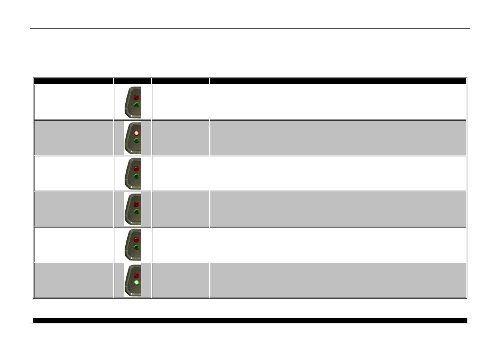
LED Blinking pat terns
Ma in
A pplies to
neoV I Red, neoVI FIRE, and neoVI Yellow
ne o VI h as 2 L EDs u se d to re p ort the sta tu s of th e d e vice . T he LEDs o n th e neo VI ca n a ls o be con tro l th rou g h a scrip t, Veh icle S py, o r cus tom ap p lica tio n. Th e ta bl e below e xpla in s a nd s h ows the com mo n bl ink in g p attern s th e
de vice can e x hib it.
Name Image Pattern Description
Powered, not running CoreMini Flashing Green This blinking sequence occurs when the device is powered and is not running a CoreMini Script.
PC Mode Flashing Red, Green
When Vehicle Spy 3 or other PC based program is connected to the neoVI, the LEDs will alternate Red, Green. Keep in mind that scripts running in Vehicle
Spy 3 can change the blinking pattern of the device.
CoreMini Mode Flashing Red
This is the default blinking pattern when running a CoreMini Script. Keep in mind that the blinki ng pattern can be changed by VehicleScape Logging or in a
function block.
VehicleScape Standalone Logging Flashing Red. Green blinking.
VehicleScape Standalone loggings changes the blinking pattern of the LEDs. The Red LED will flash at a constant rate while the Green will blink with data
being saved to Micro SD card.
VehicleScape Standalone Logging, Post trigger
Flashing Red, quickly blinking
Green
This pattern appears when working with pre/post triggers in VehicleScape Standalone loggings. The Red LED will flash at a constant rate while the Green will
blink at a fast rate with data being saved to Micro SD card for the post collection.
Boot loader 3x Green, Red
A pattern of Green, Green, Green, Red denotes boot loader mode. This mode is corrected by connecting to Vehicle Spy 3 or an application that can use the
hardware. This is a normal blinking pattern.
Table 1 - LED Blinking for neoVI F IRE, neoVI Re d , and neoV I Yellow
neo VI Doc ument ation - (C) Copyright 2000-2019 Intre pid Control Syst ems, Inc.
Intrepid Hardware Help LED Blinking
57 / 71

La st Up d ate: Friday, September 13, 2013
Intrepid Hardware Help LED Blinking
58 / 71

Hardware F eat ures - neoV I
Ma in
A pplies to
neoV I Ye llow
Th e n eo VI d e vice h as m any con fi gu rab le f eatu re s which a re n ot in -ve hi cle ne twork s . Th e h ard ware fe a ture s d iscus se d in th is section in clu de th e foll owing : 1) Ge n era l Pu rpo s e IO an d 2) Sp eci fica tio ns .
neo VI Doc ument ation - (C) Copyright 2000-2019 Intre pid Control Syst ems, Inc.
La st Up d ate: Wednes day, July 15, 2009
Intrepid Hardware Help neoVI Yellow
59 / 71
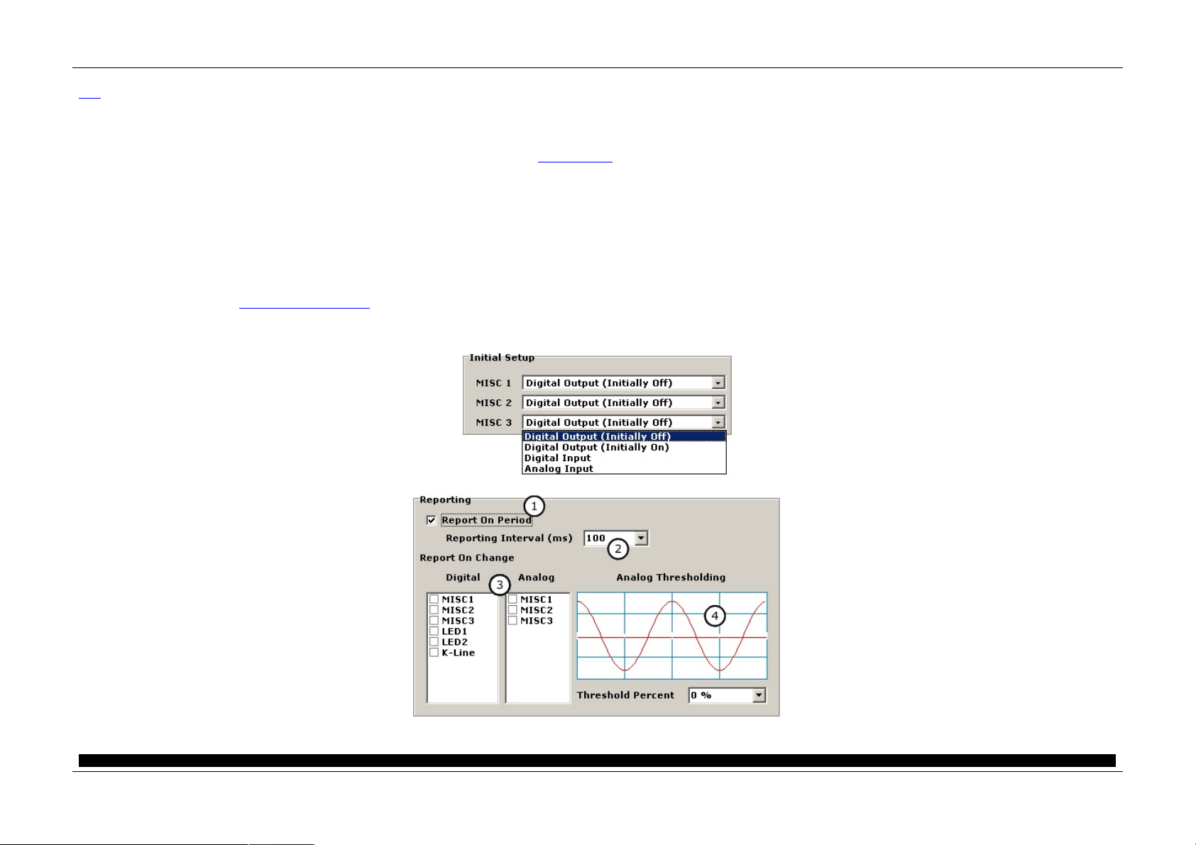
General Purpose IO
Ma in
A pplies to
neoV I Ye llow
Ov erview
ne o VI Ye llo w ha s thre e g e ne ra l p urp os e 3 .3 VDC IO p in s. T he s e a re la be le d a s MI SC s igna ls o n the n e oV I con ne cto r. T h es e p ins ca n b e us e d fo r co ntro lling o r m o nitorin g e xtern al d ev ices.
Basic Setup
Th e M ISC IO a re s etup in th e n eo VI 3 G Ex p lo rer. Fi gu re 1 sh o ws th e in pu t o utpu t co nf ig ura tio n. T h is is d on e b y s e le ctin g In itia l Valu es u nde r M ISC IO fro m th e tre e. On the p a ne l sh o wn, yo u ca n se tu p the dire ctio n, typ e , an d
ini tia l s ta te o f e a ch IO pin .
Th e o utp uts are ca p ab le o f LED driv e thro ugh a cu rren t li m itin g res is tor. The m a x im um curre nt o f a ll o utp uts s h ou ld n ot exce e d 5 m A. For pro te ctio n, e ach I O p in ha s a s e rie s 47 o hm res is tor an d a tra ns ie nt p rote ctio n devi ce.
A nalog Input s
MI SC p ins throu gh 3 ca n be s e tup a s a na lo g in pu ts . To e n ab le a n a na lo g in pu t, you ca n s el ect "An a lo g inp uts" fro m th e "I ni tia l Se tup" wind ow.
General IO Re porting
You can s e tup the ge ne ral I O to be au to m at ical ly rep o rted to the ho s t i n ne o VI 3 G Exp lo rer (f igure 2 ). You can s e tup the ge ne ral I O to be rep o rted at a n in terval o r b a se d o n d igi tal i np uts cha ng in g (f igu re 2 : b ub b le 1 ). T he
rep o rt will b e s ent to the h o st as a ne o VI De vice V irtua l Network m ess a ge .
W he n repo rting ba se d o n inte rva l is se le cte d yo u can s e le ct th e interva l fro m th e drop d own bo x s ho wn in b ub b le 2 in fi gu re 2. Yo u can s elect a n inte rva l fro m 1 to 125 m s.
If yo u se le cte d a re po rt b a se d o n di gita l cha n ge , you ca n s el ect bo th a n int erva l the inp uts a re te s te d (figu re 2 : b ubb le 2 ) a n d which d ig ita l i np uts to tes t (fig u re 2 : b ub b le 3). You ca n se le ct as m a ny a s are lis ted .
Figure 1 - neoVI MISC pins can be setup as digita l outputs, digital inputs or analog inputs.
Figure 2 - Yo u can have the neo VI de vice aut oma tically repo rt the state of MISC I O pins.
neo VI Doc ument ation - (C) Copyright 2000-2019 Intre pid Control Syst ems, Inc.
Intrepid Hardware Help General Purpose IO
60 / 71

La st Up d ate: Tues day, J anuary 08, 2013
Intrepid Hardware Help General Purpose IO
61 / 71

Specif ications
Ma in
A pplies to
neoV I Ye llow
De vice Specificat ions
• 2 DSP s a nd 1 R ISC pro ce ss o r fo r 8 8 MI PS o f pro ces s ing
• 1 MB m e ss age b uf fe r* Power Co n su m pti on ( typi cal) : 100 m A @ 14 .4 VDC
• Sle e p Power Co n su m pti on ( typi cal ) : 8 m A @ 12 .0 VDC
• P ower Sup p ly: 5.5-3 2 Volt Po wer Op e rati on
• Te m pe ra ture R a ng e : -40 C to +8 5C
• Veh icle C o nn e ctors : 15 P in m a le D -SU B
• Ge ne ra l P u rpo se IO : 3 MI SC I O (0 - 3 .3V )
• Ge ne ra l P u rpo se IO rate re p ort int erva l: 1 Hz to 10 Kh z or ba se d o n dig ita l cha ng e
• Mi cros of t© C e rtified U SB driv ers
• Is o la te d USB 2. 0 Ful l Sp e e d De vice b ack ward co m pa tib le with US B1. 1
• Sta nd -A lone M od e I nclu d ing Scriptin g , R e ce ive M es s ag e s, Tra ns m it M e ss a ge s , Ex p res si on s, I O , a n d Tran sp o rt La ye rs
• R S23 2 ho s t p ort with H W han ds h ak in g su p po rt f or scrip tin g an d ga te waying n etwork da ta
• IC S Ti m eS ync fo r Mu ltiple H a rdware Sy nch ron izati on s up ports a ll ne o VI 3G d evice s
• J2 53 4 an d R P1 210 A/B co m pa tib le f or CA N/IS O1 57 65, J1 70 8, Ke yword, a nd I SO 9141
• m icro SD ca rd s lot s up po rt u p to 1 2 G igab yte s o f s to rag e . T h e rem ova ble card is f orm atte d us in g FAT3 2 fo r d irect us a ge in a PC .
• Ba tte ry b acke d re al -tim e clo ck (R TC)
• Wa rran ty: O ne Ye a r L im ite d Wa rran ty
• Firm ware : Fie ld u pg rad e a ble de s ign ( fla s h firm ware )
Networks - General
• 64 Bi t tim e s ta m ping to a ccura cy o f 10 m icrose co nd s o n n e twork s an d ne ve r o ve rflo ws. 0.5 m icrose co nd a ccuracy tim e sta m p a va ila ble if us in g on e n etwork on ly
• Sim ultane o us o pe ra tio ns o n a ll ne twork s
• Tran s m it m ess a ge d o ub le -b uf fe rin g on a ll ne twork s a llo ws b ack to ba ck m e ss a ge tran sm ission
Network Spe cificat ions
2x J1939/CA N Channels
• 2 De di cate d I SO 11 89 8 Du al W ire C AN P hysical La ye r (T JA 10 40 )
• C AN 2.0B Active
• Up to 1 M -Bit So ft ware Selectab le Ba u d Rate (a uto b a ud ca pab le )
• C ap a ble of g ene rating a n d de te ctin g erro r fra m e s
• Lo gic An alysis of C AN Wave form with 25 n a no s eco nd res olution
• Gra ph ica l B it T im e / Ba ud R ate C al cula to r
• Lis te n only m ode s up p ort* U nte rm in ated n e twork de tectio n
J1708
• High p recis io n tim e ca p ture o f J1 70 8 bu s ev en ts
• So ftware s e le ctable p a ram ete rs includ ing b a ud ra te
• SAE J17 08 P h ysi cal la ye r
K and L Line, 1x LIN (Local Interconnect ), ISO 9141, or Key word 2000
• UA RT B as e d Sta te Mach ine
• In itiali za tio n Wa ve fo rm s incl ud ing Fast Init, Fiv e Ba ud , an d C us tom
• P rog ram ma bl e Ti m ing P a rame ters incl ud ing I n ter- Byte , TX In te r-Fra m e , R X In te r-Fra m e a nd I ni tia liz ation W ave form s (0 .5 m s R eso lu tio n) Fu ll s u pp ort fo r LIN 1 .X, 2. X a n d J2602
• K a n d L h a ve s of tware contro lle d tra ns m it e n able l ine s a llo wing m a ny diffe ren t v aria n ts of U AR T o r IS O9 141 co m mun ications in cludin g: Tx on L Rx on K (f ull dup le x) ;T x a nd R x o n K ( ha lf d up le x);T x o n K a n d L a n d Rx on K
• So cket se le cta ble pu ll up re s istor o n b oth K a nd L lin e s
• C ap a ble of Ge n eratin g LI N Wa ve fo rm s (I ncl ud ing Erro rs) U sin g De d icat ed O u tpu t C o m pare H ardware
• So ftware Selecta b le Ba u d Ra te
• LI N Bu s Mo ni tor Mo de ide ntifie s e rrors : Syn c Bre a k Error Sta te a nd Len gth, Syn c Wa ve Error, Me s sa g e ID p arity, TF ram eMa x /Sl ave Not Re s po n ding , C h eck s um Error a nd Tra ns m it Bit Errors.
• LI N Bu s Ma ster Mo de op era te s a t s am e ti m e as LIN Bus M onito r
• LI N Bu s Sla ve s im ulat ion - with or withou t an LDF f ile
• LI N Bu s ha rdware sch ed u le ta bl e with s up p ort fo r LI N d ia gn o stics G M Clas s 2/ SAE J1 85 0 VPW
• VP W P hys ica l La ye r capa ble o fT x and R x o pe ra tio ns in h ig h sp e ed m ode s (MC 33 39 0)
• R ece p tio n of I FR d ata du ring rx an d tx
• Lo ng M e ss a ge tran sm it an d re cep tio n fo r EC U fla s hin g
neo VI Doc ument ation - (C) Copyright 2000-2019 Intre pid Control Syst ems, Inc.
La st Up d ate: Tues day, J anuary 08, 2013
Intrepid Hardware Help Specifications
62 / 71

Hardware Settings
Ma in
A pplies to
neoV I Ye llow
W hil e m os t n e oVI se ttin g s are s o ftware p rog ra m m ab le a fe w are s et with ha rdware . T he p u ll u p resis to rs fo r th e UART /I SO /Keyword 2 k network
Table 1 - Hardware Sett ings in the neoVI dev ice
Sett ing Bubble in Figure 1 Inst ructions
K a nd L li ne p ull-u p res is to rs A
In se rt two 0 .25 W res is tors e n d to end with de s ired p u ll u p va lues ( 51 0
O hm s a re the fa ctory def au lt)
Figure 1 - The K-Line pull-ups.
neo VI Doc ument ation - (C) Copyright 2000-2019 Intre pid Control Syst ems, Inc.
La st Up d ate: Thursday, July 09, 2009
Intrepid Hardware Help Hardware Settings
63 / 71

Hardware F eat ures
Ma in
A pplies to
ValueCAN 3
Th e Val ue C AN 3 ha s f ew co nf igu ra ble fe ature s which are n o t in -ve h icle n e twork. T he G en e ral P urp os e I O a nd Spe cifi cati on s se ctio n s cove r th e no n n etwork fe ature s.
neo VI Doc ument ation - (C) Copyright 2000-2019 Intre pid Control Syst ems, Inc.
La st Up d ate: Wednes day, July 15, 2009
Intrepid Hardware Help ValueCAN 3
64 / 71

Intrepid Hardware Help General Purpose IO
65 / 71

Intrepid Hardware Help Specifications
66 / 71

Relat ed Inf o - neoV I
Ma in
Th e to pi c o f i n-veh icle ne twork s can b e a co m plex on e. T hi s se ctio n de ta ils s o m e re so urce s to h elp le arn m o re a bo u t th em . Th e re so u rces a re th e fo llo wing : 1 ) SAE O BD Bo o k, 2 ) I n tern e t R e so urces a nd 3 ) Glo ss a ry.
neo VI Doc ument ation - (C) Copyright 2000-2019 Intre pid Control Syst ems, Inc.
La st Up d ate: Wednes day, April 11, 2001
Intrepid Hardware Help Related Info
67 / 71

SA E OBD Book - neoVI
Ma in
SA E On-B oard D iagnost ics for Light and Medium Duty Vehicles Sta ndards Manual 1999 Edition
Edition: 1
Con te nts in clu de : Ele ctrical /Ele ctronic System s Di ag no s tic Te rm s , D ef ini tio ns , Abb re via tio ns a nd A cron ym s; Diag n os tic Co n ne cto r; O BD I I Scan To o l; E/E Di ag n os tic Tes t M ode s; R e com me nd e d P ractice fo r Dia g no s tic Tro ub le C o de
De fin itio n s; E/E Da ta Lin k Se cu rity; Enh an ce d E/E Di ag no s tic Te s t M od e s; C la ss B C ommu n icat ion s Ne twork In te rfa ce; C la s s B Da ta C o m m un ica tio n Network Me ss a ge s - De ta ile d He a der Forma ts P hy sica l Addre ss A ss ig nm e nts;
Clas s B Da ta C om mu nica tio n Network Me ss a ge s - P art 2: Da ta P a ram ete r De fi niti on s; C la s s B Da ta C o m m un ica tio n Network Me ss a ge s - P art 3: Fra m e I Ds fo r Si ng le Byte Fo rm s of He a d ers ; Cl as s B D ata Com m u nication
Network M e ss a ge s - Me s sa g e De fin ition s fo r T hre e Byte He a de rs; a n d Biblio gra phy of R e lated S AE Te chn ica l P a pe rs .
Th is b oo k co ntains a ll of th e fo llo wing s pe cif icat ion s : J 18 50 , J 19 62 , J19 79 a n d oth e r d ia gn os tic sp e cifica tio n s.
ISBN Numbe r: 0 -7 68 0-0 337 -7
Da te P ublished: J un e 19 99
40 8 Pa g es
Binding: P a pe rb ou nd
Product Code: HS -30 00 /9 9
Pu rcha s e fro m th e SAE webs ite ( http :/ /www.sa e. org ). Se a rch o n HS -3 00 0 as th e re m ay be up da te s .
neo VI Doc ument ation - (C) Copyright 2000-2019 Intre pid Control Syst ems, Inc.
La st Up d ate: Sunday, April 22, 2001
Intrepid Hardware Help SAE OBD Book
68 / 71

Internet Resourc es - neoV I
Ma in
Intrepid Control Sys tem s, Inc. Sites
Ma in We b site www.int rep id cs.co m
ne o VI We bsite www.intre p idcs .co m /n e ovi /
Veh icle Sp y W eb s ite www.in trepid cs. com /vsp y/
In-v ehicle Network Specifica tions
SAE ( So cie ty o f Auto m o tive En gi ne e rs) J1 85 0, J1708 , J 19 39 , J 19 79 , J 19 62 , etc. : www.sa e .o rg
LI N (L oca l In te rcon ne ct Ne twork ) : www.lin- su bb us.o rg
Bo sch (C o ntroll er Area Network Spe cifi cati on ) : www. can .b o sch .co m
ISO (I nte rn ati on a l O rgan iz ati on f ro Sta nd a rdiz a tio n) www.is o. ch
US EPA O BD- II Site www.e pa .g o v/o m s/o bd .h tm
CARB (C a lif orn ia Ai r R es o urce s Bo ard) www.arb.ca .g ov
neoV I Silicon Vendors
Micro chi p Tech no lo g y : M CP2 51 0 CA N C on trolle r www.m icro chip .co m
Ph ili ps : Du al W ire ( 82 C2 51 ) an d Lo w Sp ee d Fau lt Tolera nt (T JA 10 54 ) Tra nsce ive rs www.ph ili ps .co m
In fin e on : Sing le W ire C AN Tra ns ce ive r T LE6 25 5 www.inf ine o n. com
Mo to rola : J 18 50 VP W P h ysi cal La ye r M C3 3390 Tra n sce ive r a n d LBC C Fo rd SC P C om mu nica tio n s IC www. m ot-sps .co m
neo VI Doc ument ation - (C) Copyright 2000-2019 Intre pid Control Syst ems, Inc.
La st Up d ate: Tues day, March 26, 2002
Intrepid Hardware Help Internet Resources
69 / 71

Glossary - neoVI
Ma in
A LDL - As se m b ly Lin e Da ta Li nk - T he p re -O BD- II co m m u nica tio ns link fo un d on G M vehicle s .
A rbitrat ion ID (A rb ID ) - Th e id e nti fie r p ortion o f the CAN (C o ntro lle r Are a Ne twork ) m ess a ge .
CA RB - C a lif orn ia Air R es o urce s Bo ard - Ag e ncy in Cali fo rnia which s e ts emiss io n sta n da rd s which re la te to O BD.
CA N - Contro lle r Are a Ne twork - A veh icle n et work which ha s m e ss a ge s which conta in a n Arbitra tio n ID (Arb ID) fie ld, a DL C da ta length co de fiel d and an eig h t byte da ta fiel d. Th e Arb I D can be 11 bits or 29 bits . T hi s
sp e cifica tio n was re le ase d by Bo sch .
Class 2 - Ge nera l Mo tors m ess a gi ng s trateg y b a se d o n the VPW pa rt o f the J 18 50 s pe cif ica tio n.
Ford SCP - Fo rd Mo to r C om pan y mes sag in g stra te gy bas e d on th e P W M pa rt o f the J 18 50 s pecif ica tio n
GMLAN - Gen e ral Mo to rs m es s ag in g stra te g y u sin g C AN. T h is stra te g y is p la nn e d to repla ce th e C la ss 2 m e ssa ging s tra teg y (J1 85 0) .
ID B - I nf otain m e nt da ta b us - Differe nt s pe cifi cati on s related to in- ve hicle inf orm atio n an d e nte rta in m en t d a ta b us es. ID B-C i s a sp e cifica tio n th at us e s du a l wire C AN.
ISO 9141 - A U AR T b as e d pro to col which is a llo wed und er O BD-I I .
J1587 - Stan dard which d ef ines m ess a ging p ack e ts fo r J 17 08 p hys ica l lay er ne twork s.
J1708 - P h ysical La ye r s pe cif ication a n d Pro to col fo r u sing a R S4 85 s tyle ne twork . U se d in tru ck a nd b us a p plication s .
J1850 - P h ysi cal La ye r a nd Pro to col spe cifi cati on f or no rth Am e rican in- vehicle com m u nication s. I t co ns is ts o f two phys ica l laye rs VP W a n d PW M which sh a re si m ila r d ata fo rm ats . Th is in clu de s a 1 1 byte m es s ag e with a C RC. I n-
fra m e resp on s es a re a ls o avai la ble in the p ro toco l.
J1939 - Spe cifi cati on f or com m u nica tio n s fo r He a vy Truck a nd B us b as e d on C AN m e ssa ges u si ng a 2 9 bit Arb I D.
J1962 - Spe cifi cati on d e tai lin g the d ia g no stic co nn ector fo un d in North Am erica n veh icle s . T h is con ne ctor is a lso called t he O DB -I I con ne cto r a nd th e AL DL con ne ctor.
J1979 - Spe cifi cati on s which de ta il O DB-II te s t m o de s a nd d a ta. T hi s inclu d es re q ue s ting value s fro m th e Veh icle s uch a s R PM, Eng ine Loa d , C o o la nt Tem p, Ve hicle Spe e d, Etc.
Key word 2000 - An e nh an ce d ve rsio n o f I SO 9 14 1 which s pecif ie s m any dia g no s tics se rvice s .
LIN - Lo ca l I nte rcon ne ct Network - A UAR T b a se d network which co n sis t o f a m a ste r an d m any sla ve n o de s .
Messaging Strate gy - T hi s is a high e r-le ve l p ro toco l which d e fin e s ho w the co n ten t o f ve hi cle ne twork m ess a ge s is u sed a nd whe n m e ss a ge s a re tra ns m itte d.
OBD - O n -b oa rd Dia g no s tics - Software in si de th e Vehicle which a u tom atica lly di ag no s e s the Ve hicle. O BD- II s pecif ie s di ag no s tics s ervi ces re q uire d b y la w in North Am erica .
Phy sical Layer - Th e e le ctrica l s ig na lin g po rtio n o f a pro tocol.
PW M - P uls e W id th Mo d ula tio n - Th is typ e o f el ectrica l cod in g is us e d in the J1 85 0 sp ec PWM p rot oco l.
RS232 - P C co m m un ica tio n po rt which ca n op e rate at spe e ds b e twee n 30 0 a n d 11 5k bits p e r s eco n d.
SA E - So cie ty o f Au tom otive En gi ne e rs (www.sae .o rg )
UA RT - Un ive rsa l Asy nch ron ou s R eceiv er Tran sm itter - A ne twork p rotoco l ba se d o n a UAR T f ou nd o n m a ny m icrocon trol le rs.
USB - U ni vers a l Seria l Bus - A 12 m e gab its p e r se co nd b us co m m u nica tio n p ort.
VP W - Va riable P u ls e W idth - T hi s type of e le ctrical co di ng is u se d in th e J1 850 spe c VP W p ro toco l.
neo VI Doc ument ation - (C) Copyright 2000-2019 Intre pid Control Syst ems, Inc.
La st Up d ate: Wednes day, April 11, 2001
Intrepid Hardware Help Glossary
70 / 71

Contact Information
Intrepid Control Systems, Inc.
31 60 1 Re sea rch Park D r.
Ma d iso n He ig h ts, MI 4 80 71 U SA
(p h) 58 6.73 1. 79 50
(fa x ) 58 6. 73 1.2 274
(e m a il)
(website) www.intrepidcs.com
neo VI Doc ument ation - (C) Copyright 2000-2019 Intre pid Control Syst ems, Inc.
Last Update: Monday, September 16, 2013
Intrepid Hardware Help Contact
71 / 71
 Loading...