

intrepid 6140 Director Installation And Service Manual
Intrepid®6140 Director
Installation and Service Manual
380 Interlocken Crescent Broomfield, CO 80021-3464
Corporate Headquarter s:
Sales E-mail:
sales@mcdata.com
800-545-5773
Web:
www.mcdata.com
P/N 620-000157-420
REV A

Record of Revisions and Updates
Revision Date Description
620-000157-000 9/2002 Initial release of the manual
620-000157-100 10/2002 Updates to describe Release 6.2 and 6.3 of the
620-000157-200 2/2003 Updates to describe Release 7.1 of the Enter-
620-000157-201 6/2003 Updates to describe new firmware and software
620-000157-300 8/2003 Revision of the manual to describe the one unit
620-000157-400 12/2003 Revision of the manual to describe Release
Enterprise Fabric Connectivity Manager application.
prise Fabric Connectivity Manager application.
New cover and new format.
download procedures from McDATA’s home
page.
(1U) rack-mount server and Release 7.2 of the
Enterprise Fabric Connectivity Manager application.
8.0/8.1 of the Enterprise Fabric Connectivity
Manager application. New style for safety
notices. Addition of translated safety notices.
620-000157-420 7/2005 Revision of the manual to describe Release 8.7
Copyright © 2002 - 2005 McDATA Corporation. All rights reserved.
Printed July 2005
ii
Intrepid® 6140 Director Installation a n d Service Manual
of the Enterprise Fabric Connectivity Manager
(EFCM) and EFCM Basic Edition application
and functionality.

Seventh Edition
No part of this publication may be reproduced or distributed in any form or by anymeans, or stored in a
database or retrieval system, without prior written consent of McDATA Corporation.
The information contained in this document is subject to change without notice. McDATA Corporation
assumes no responsibility for any errors that may appear.
All computer software programs, including but not limited to microcode, described in this document are
furnished under a license, and may be used or copied only in accordance with the terms of such license.
McDATA eitherowns or has theright to licensethe computer softwareprograms described inthis document.
McDATA Corporation retains all rights, title and interest in thecomputer software programs.
McDATA Corporationmakes no warranties, expressedor implied, by operation of law or otherwise,relating
to this document, the products or the computer software programs described herein. McDATA
CORPORATION DISCLAIMS ALL IMPLIED WARRANTIES OF MERCHANTIBILITY AND FITNESS FOR
A PARTICULAR PURPOSE. In no event shallMcDATA Corporation be liable for (a) incidental, indirect,
special, or consequential damages or (b) any damages whatsoever resulting from the loss of use, data or
profits, arising out of this document, even if advised of the possibility of such damages.
Intrepid® 6140 Director Installation and Service Manual
iii

iv
Intrepid® 6140 Director Installation a n d Service Manual

Contents
Preface..........................................................................................................................xvii
Chapter 1 General Information
Director Description .........................................................................1-1
Field-Replaceable Units ...................................................................1-4
Power/System LED Assembly................................................1-5
CTP Card.....................................................................................1-5
UPM Card...................................................................................1-7
XPM Card ...................................................................................1-8
SFP and XFP Transceivers........................................................1-9
Power Supply...........................................................................1-10
AC Module ...............................................................................1-11
Fan Module...............................................................................1-11
SBAR Assembly ....................................................................... 1-11
Backplane..................................................................................1-12
Error-Detection, Reporting, and Serviceability Features ..........1-12
Element Manager Status Indicators .............................................1-14
Tools and Test Equipment..............................................................1-15
Tools Supplied with the Director...........................................1-15
Tools Supplied by Service Personnel....................................1-17
Director Management ....................................................................1-18
Chapter 2 Installation Tasks
Factory Defaults ................................................................................2-1
Installation Task Summary..............................................................2-3
Task 1: Verify Installation Requirements.......................................2-5
Task 2: Unpack, Inspect, and Install the Ethernet Hub (Optional).
2-5
Contents
v

Contents
Unpack and Inspect Ethernet Hub .........................................2-6
Desktop Installation ..................................................................2-6
Rack-Mount Installation...........................................................2-8
Task 3: Unpack, Inspect, and Install the Director.........................2-9
Task 4: Configure Director at the EFCM Basic Edition Interface
(Optional).........................................................................................2-11
Configure Director Identification..........................................2-13
Configure Date and Time....................................................... 2-13
Configure Parameters.............................................................2-14
Configure Fabric Parameters ................................................. 2-16
Configure Network Information...........................................2-18
Configure Basic Port Information .........................................2-19
Configure Port BB_Credit ......................................................2-20
Configure Port NPIV...............................................................2-21
Configure SNMP .....................................................................2-21
Enable CLI ................................................................................2-23
Enable or Disable Host Control.............................................2-23
Configure SSL Encryption......................................................2-24
Install PFE Key s (Optional)....................................................2-25
Configure Security...................................................................2-28
Configure Interswitch Links ..................................................2-29
Task 5: Configure Director Network Information (Optional) ..2-30
Task 6: Unpack, Inspect, and Install the Management Server..2-34
Task 7: Configure Server Password and Network Addresses..2-36
Configure Password................................................................2-36
Configure Private LAN Addresses.......................................2-37
Configure Public LAN Addresses (Optional).....................2-38
Task 8: Config ure Management Server Information .................2-38
Access the M anagement Server Desktop.............................2-38
Configure Management Server Names................................2-39
Configure Gateway and DNS Server Addresses................2-40
Task 9: Co nfig ure Windows Operating System Users ..............2-42
Change Default Administrator Password ...........................2-42
Add a N ew User......................................................................2-42
Change User Properties..........................................................2-43
Task 10: Set Management Server Date and Time .......................2-44
Task 11: Configure the Call-Home Feature (Optional)..............2-46
Task 12: Assign User Names and Passwords .............................2-47
Task 13: Configure the Director to the Management Application..
2-48
Task 14: Record or Verify Server R estore Information ..............2-49
Task 15: Verify Director-to-Server Communication...................2-50
Task 16: Co nfigure PFE Key (Optional).......................................2-51
vi
Intrepid® 6140 Director Installation a n d Service Manual

Contents
Task 17: Config ure Management Server (Optional)..................2-53
Task 18: Set Director Date and Time............................................2-54
Task 19: Co nfig ure the Element Manager Application ............. 2-55
Configure Director Identification.........................................2-56
Configure Director Parameters.............................................2-56
Configure Fabric Parameters.................................................2-58
Configure Ports .......................................................................2-60
Configure SNMP.....................................................................2-61
Configure Threshold Alerts...................................................2-62
Enable EFCM Basic E dition and Telnet Access .................. 2-65
Configure, Enable, and Test E-mail Notification ............... 2-65
Configure and Enable Ethernet Events................................2-67
Configure, Enable, and Test Call-Home Event Notification ....
2-67
Configure Security.................................................................. 2-68
Configure Interswitch Links..................................................2-69
Task 20: Back Up Configuration Data .........................................2-70
Task 21: Cable Fibre Channel Ports .............................................2-73
Task 22: Configure Zoning (Optional) ........................................2-73
Task 23: Connect Director to a Fabric Element (Optional)....... 2-74
Task 24: Regis ter with the McDATA Filecenter .........................2-75
Chapter 3 Maintenance Analysis Procedures (MAPS)
Factory Defaults ............................................................................... 3-1
Quick Start......................................................................................... 3-2
MAP 0000: Start MAP......................................................................3-8
MAP 0100: Power Distribution Analysis....................................3-13
MAP 0200: POST Failure Analysis .............................................. 3-16
MAP 0300: Loss of Server Communication................................3-20
MAP 0400: FRU Failure Analysis.................................................3-30
MAP 0500: Port Failure or Link Incident Analysis.................... 3-34
MAP 0600: Fabric or ISL Problem Analysis ...............................3-48
Chapter4 RepairInformation
Factory Defaults ........................................................................4-2
Procedural Notes.......................................................................4-2
Obtaining Log Information.............................................................4-3
SAN Management Logs...........................................................4-3
Element Manager Logs ............................................................ 4-5
EFCM Basic Edition Logs......................................................... 4-8
Obtaining Port Diagnostic Information...................................... 4-11
Contents
vii

Contents
Port LED D iagnostics..............................................................4-11
Element Manager Application Diagnostics.........................4-12
EFCM Basic Edition Diagnostics...........................................4-17
Performing Loopback Tests...........................................................4-21
Internal Loopback Test (Element Manager Application)..4-21
External Loopback Test (Element Manager Application) .4-23
Internal Loopback Test (EFCM Basic Edition) ....................4-24
External Loopback Test (EFCM Basic Edition) ...................4-26
Blocking and Unblocking Ports....................................................4-27
BlockorUnblockaPortorPortCard(ElementManagerAp-
plication)...................................................................................4-27
Block or Unblo ck a Port (EFCM Basic Edition)...................4-28
Swapping Ports...............................................................................4-29
Performing Channel Wrap Tests (FICON)..................................4-31
Collecting Maintenance Data........................................................4-32
Collecting Maintenance Data (Element Management Appli-
cation)........................................................................................4-32
Collecting Maintenance Data (EFCM Basic Edition)..........4-33
Powering the Director On or Off..................................................4-34
Power-On Procedure ..............................................................4-34
Power-Off Procedure ..............................................................4-35
Setting the Director Online or Offline..........................................4-36
Set Online or Offline (Element Manager Application) ......4-36
Set Online or Offline (EFCM Basic Edition) ........................4-37
IML, IPL, or Reset the Director.....................................................4-38
IML the Director (CTP Front Panel) .....................................4-38
IPL the Director (Element Manager Application) ..............4-39
Reset the Director (CTP Front Panel) ..................................4-39
Cleaning Fiber-Optic Components ..............................................4-40
Downloading Director Firmware and Software ........................4-41
Download Firmware and Software from Filecenter ..........4-42
Download Firmware and Software to Director (Element
Manger Application)...............................................................4-44
Download Firmware and Software to Director (EFCM Basic
Edition)......................................................................................4-46
Installing or Upgrading Software................................................. 4-47
Managing Configuration Data......................................................4-50
Back Up Configuration (Element Manager Application)..4-50
Restore Configuration (Element Manager Application)....4-50
Reset Configuration Data (Element Manager Application).....
4-51
Back Up Conf iguration (EFCM Basic Edition)....................4-54
Restore Configuration (EFCM Basic Edition)......................4-54
viii
Intrepid® 6140 Director Installation a n d Service Manual

Reset Configuration Data (EFCM Basic Edition) ...............4-55
Chapter 5 Removal and Replacement Procedures (RRPs)
Factory Defaults ........................................................................5-1
Procedural Notes.......................................................................5-2
Removing and Replacing FRUs.....................................................5-3
ESD Information........................................................................5-3
Concurrent FRUs.......................................................................5-5
Nonconcurrent FRU .................................................................5-5
RRP: CTP Card ................................................................................. 5-6
RRP: Port Module Card (UPM and XPM).................................. 5-11
RRP: Optical Transceiver (SFP and XFP).................................... 5-17
RRP: Filler Panel (UPM and XPM) ..............................................5-21
RRP: Power Supply........................................................................5-23
RRP: AC Module............................................................................5-26
RRP: Fan Module ...........................................................................5-30
RRP: Power/System Error LED Assembly ................................5-34
RRP: SBAR Assembly....................................................................5-36
RRP: Backplane ...............................................................................5-40
Contents
Chapter 6 Illustrated Parts Breakdown
Front-Accessible FRUs.....................................................................6-2
Rear-Accessible FRUs ......................................................................6-4
Miscellaneous Parts .........................................................................6-7
Power Cords and Receptacles........................................................6-9
Appendix A Event Code Tab les
System Events (000 through 1 99) .................................................A-3
Power Supply Events (200 through 299) ...................................A-26
Fan Module Even ts (300 through 399) ......................................A-30
CTP Card Events (400 through 499) ..........................................A-38
Port Card (UPM and XPM) Events (500 th rough 599) ............A-49
SBAR Events (600 through 699) .................................................A-61
Thermal Events (800 through 899) .............................................A-67
Appendix B Director Specifications
Physical Characteristics............................................................B-1
Shipping and Storage Environment.......................................B-2
Operating Environment...........................................................B-2
Fabricenter Equipment Cabinet Service Clearances............B-3
Contents
ix

Contents
Appendix C Management Server and Ethernet H ub
Management Server Description...................................................C-1
Management Server Specifications........................................C-2
Ethernet Hub Description ..............................................................C-2
Appendix D Restore Management Server
Requirements ...................................................................................D-1
Restore M anagement Server Procedure ......................................D-2
Appendix E Safety Notices (Multi-Lingual Translations)
Glossary
........................................................................................................................g-1
Index ................................................................................................................................i-1
x
Intrepid® 6140 Director Installation a n d Service Manual

Figures
1-1 Cabinet-Mounted Intrepid 6140 Directors and Management Server ... 1-3
1-2 Director FRUs (Front Access) ..................................................................... 1-4
1-3 Director FRUs (Rear Access) ....................................................................... 1-5
1-4 UPM Card LEDs and Connectors .............................................................. 1-8
1-5 XPM Card LEDs and Connectors ............................................................... 1-9
1-6 Small Form-Factor Pluggable (SFP) transceiver .................................... 1-10
1-7 Ten Gbps Form-Factor Pluggable (XFP) Transceiver ............................ 1-10
1-8 Torque Tool and Hex Adapter ................................................................. 1-16
1-9 Door Key ...................................................................................................... 1-16
1-10 Loopback Plug ............................................................................................ 1-16
1-11 Fiber-Optic Protective Plug ....................................................................... 1-17
1-12 Null Modem Cable ..................................................................................... 1-17
2-1 Patch Cable and MDI Selector Configuration .......................................... 2-7
2-2 Mounting Bracket Installation (Ethernet Hub) ........................................ 2-8
2-3 AC Power Connections (Director) ........................................................... 2-10
2-4 Identification View ..................................................................................... 2-13
2-5 Date Time View .......................................................................................... 2-14
2-6 Parameters View ......................................................................................... 2-15
2-7 Fabric Parameters View ............................................................................. 2-16
2-8 Network View ............................................................................................. 2-18
2-9 Basic Information View ............................................................................. 2-20
2-10 SNMP View ................................................................................................. 2-22
2-11 CLI View ...................................................................................................... 2-23
2-12 OSMS View .................................................................................................. 2-24
2-13 SSL View ...................................................................................................... 2-25
2-14 Maintenance Feature Installation View .................................................. 2-28
2-15 Connection Description Dialog Box ........................................................ 2-32
2-16 1U Management Server Connections ...................................................... 2-35
Figures
xi

Figures
2-17 Identification Changes Dialog Box ........................................................... 2-40
2-18 Internet Protocol (TCP/IP) Properties Dialog Box ................................. 2-41
2-19 Add New User Wizard ............................................................................... 2-43
2-20 Properties Dialog Box (General Tab) ........................................................ 2-44
2-21 Date/Time Properties Dialog Box (Time Zone Tab) .............................. 2-45
2-22 Date/Time Properties Dialog Box (Date & Time Tab) .......................... 2-46
2-23 Add User Dialog Box .................................................................................. 2-47
2-24 Address Properties Dialog Box (IP Address Page) ................................ 2-49
2-25 New Feature Key Dialog Box .................................................................... 2-53
2-26 Configure Date and Time D ialog Box ...................................................... 2-54
2-27 Configure Identification Dialog Box ........................................................ 2-56
2-28 Configure Switch Parameters Dialog Box ............................................... 2-57
2-29 Configure Fabric Parameters Dialog Box ................................................ 2-58
2-30 Configure Ports Dialog Box ....................................................................... 2-60
2-31 Configure SNMP Dialog Box .................................................................... 2-62
2-32 New Threshold Alert Dialog Box (Screen 1) ........................................... 2-63
2-33 New Threshold Alert Dialog Box (Screen 2) ........................................... 2-64
2-34 New Threshold Alert Dialog Box (Screen 3) ........................................... 2-65
2-35 Email Event Notification Setup Dialog Box ............................................ 2-66
2-36 InCD Icon (Unformatted CD) .................................................................... 2-71
2-37 McDATA Filecenter Home Page .............................................................. 2-76
3-1 Daisy-Chained Ethernet Hubs .................................................................. 3-24
3-2 UPM Card Diagram (Front) ....................................................................... 3-44
3-3 UPM Card Diagram (Rear) ........................................................................ 3-44
4-1 Port List View .............................................................................................. 4-13
4-2 Port Properties D ialog Box ........................................................................ 4-15
4-3 Port Technology Dialog Box ...................................................................... 4-17
4-4 Port List View .............................................................................................. 4-18
4-5 Port Diagnostics Dialog Box ...................................................................... 4-22
4-6 Diagnostics View ......................................................................................... 4-25
4-7 Basic Information View .............................................................................. 4-29
4-8 Swap Ports D ialog Box ............................................................................... 4-30
4-9 Save Data Collecti on Dialog Box .............................................................. 4-32
4-10 System Files View ....................................................................................... 4-33
4-11 Set Online State Dialog Box ....................................................................... 4-37
4-12 Switch View ................................................................................................. 4-37
4-13 Clean Fiber-Optic Components ................................................................ 4-41
4-14 McDATA Filecenter Home Page .............................................................. 4-42
4-15 Firmware Library Dialog Box .................................................................... 4-44
4-16 Firmware Upgrade View ........................................................................... 4-46
4-17 InstallShield Wizard Dialog Box ............................................................... 4-48
xii
Intrepid® 6140 Director Installation a n d Service Manual

4-18 Backup and Restore Configuration Dialog Box ..................................... 4-50
4-19 Reset Configuration Dialog Box ............................................................... 4 -51
4-20 Discover Setup Dialog Box ........................................................................ 4-52
4-21 Address Properties Dialog Box ................................................................ 4-53
4-22 Backup Configuration View ..................................................................... 4-54
4-23 Restore Configuration View ..................................................................... 4-55
5-1 ESD Grounding Points ................................................................................. 5-4
5-2 CTP Card Removal and Replacement ....................................................... 5-8
5-3 UPM Card Removal and Replacement ................................................... 5-13
5-4 SFP Optical Transceiver Removal and Replacement ............................ 5-18
5-5 Filler Panel Removal and Replacement ................................................... 5-22
5-6 Power Supply Removal and Replacement ............................................. 5-24
5-7 AC Module Removal and Replacement .................................................. 5-27
5-8 Fan Module Removal and Replacement ................................................. 5-31
5-9 Power/System Error LED Assembly Removal and Replacement ...... 5-35
5-10 SBAR Assembly Removal a n d Replacement .......................................... 5-37
5-11 Backplane Removal and R eplacement .................................................... 5-42
Figures
6-1 Front-Accessible FRUs ................................................................................. 6-2
6-2 Rear-Accessible FRUs (Part 1) .................................................................... 6-4
6-3 Rear-Accessible FRUs (Part 2) .................................................................... 6-6
6-4 Miscellaneous Parts ...................................................................................... 6-7
6-5 Power Cords and Receptacles .................................................................... 6-9
C-1 Management Server ..................................................................................... C-1
C-2 24-Port Ethernet Hub ................................................................................... C-3
D-1 Run Dialog Bo x ............................................................................................ D-3
D-2 VNC Authentication Screen ....................................................................... D-5
D-3 Welcome to Windows D ialog Box ............................................................ D-5
D-4 Log On to Windows Dialog Box ............................................................... D-6
D-5 EFCM Log In or SANavigator Log In Log In Dialog Box ...................... D-6
Figures
xiii

Figures
xiv
Intrepid® 6140 Director Installation a n d Service Manual

Tables
1-1 Element Manager Alert Symbols, Messages, and Status ...................... 1-14
2-1 Factory-Set Defaults (Director) ................................................................... 2-1
2-2 Factory-Set Defaults (Management Server) .............................................. 2-2
2-3 Installation Task Summary ......................................................................... 2-3
2-4 Operational States and Symbols ............................................................... 2-51
3-1 Factory-Set Defaults ..................................................................................... 3-1
3-2 MAP Summary ............................................................................................. 3-2
3-3 Event Codes versus Maintenance Action ................................................. 3-2
3-4 MAP 100 Even t Codes ............................................................................... 3-13
3-5 MAP 200 Even t Codes ............................................................................... 3-16
3-6 MAP 200: Byte 0 FRU Codes ..................................................................... 3-16
3-7 MAP 300 Erro r Messages .......................................................................... 3-22
3-8 MAP 400: Event Codes .............................................................................. 3-30
3-9 MAP 500: Event Codes .............................................................................. 3-34
3-10 Link Incident Messages ............................................................................. 3-35
3-11 Invalid Attachment Reasons a nd Actions ............................................... 3 -36
3-12 Inactive Port Reasons an d Actions ........................................................... 3-41
3-13 MAP 600 Event Codes ............................................................................... 3-48
3-14 E_Port Segmentation Reasons and Actions ............................................ 3-50
3-15 Port Fence Codes and Actions .................................................................. 3-55
3-16 Fabric Merge Failure Reasons and Actions ............................................ 3-58
4-1 Factory-Set Defaults ..................................................................................... 4-2
4-2 Port Operational States .............................................................................. 4-11
5-1 Factory-Set Defaults ..................................................................................... 5-1
5-2 Concurrent FRUs .......................................................................................... 5-5
Tables
xv

Tables
5-3 Nonconcurrent FRU ...................................................................................... 5-5
6-1 Front-Accessible FRU Parts List .................................................................. 6-3
6-2 Rear-Accessible FRU Parts List (Part 1) ..................................................... 6-5
6-3 Rear-Accessible FRU Parts List (Part 2) ..................................................... 6-6
6-4 Miscellaneous Parts ...................................................................................... 6-8
6-5 Power Cord and Receptacle List ............................................................... 6-10
xvi
Intrepid® 6140 Director Installation a n d Service Manual

Preface
This publication is part of a documentation suite that supports the
McDATA® Intrepid® 6140 (ED-6140) Director.
Who Should Use This
Manual
Organization of This
Manual
This publication is intended for use by installation and service
representatives experienced with the director, storage area network
(SAN) technology, and Fibre Channel technology.
This publicationincludessix chapters and four appendicesorganized
as follows:
Chapter 1, General Information. This chapter describes the
maintenance approach to director problem analysis and repair.
The chapter provides a description of the director and associated
Enterprise Fabric Connectivity (EFC) Server, specifications,
remote workstation configurations and minimum specifications,
field-replaceable units (FRUs), switches, connectors, and
indicators, software diagnostic features, and tools and test
equipment.
Chapter 2, Installation Tasks. This chapter describes tasks to install,
configure, and verify operation of the director and management
server. The director can be installed on a desktop, mounted in a
®
McDATA-supplied FC-512 Fabricenter
equipment cabinet, or
mountedinanystandard19-inchequipmentrack.
Intrepid® 6140 Director Installation and Service Manua ll
xvii

Preface
Chapter 3, Maintenance Analysis Procedures (MAPS). This chapter
describes maintenance analysis procedures (MAPs) to fault
isolate a director problem to an individual FRU.
Chapter 4, Repair Information. This chapter describes
supplementary diagnostic and repair procedures for a failed
director. The chapter includes procedures to display and use log
information, perform port diagnostics, manage configuration
data, collect maintenance data, power-on, power-off, and initial
program load (IPL) the director, set the director online or offline,
block ports, manage director firmware, clean fiber optics, and
install or upgrade management server software.
Chapter 5, Removal and Replacement Procedures (RRPs).This
chapter describes procedures to remove and replace director
FRUs.
Chapter 6, Illustrated Parts Breakdown. This chapter illustrates,
describes, and shows the location of director FRUs. In addition,
FRUs are cross-referenced to corresponding part numbers.
Appendix A, Event Code Tables This appendix provides an
explanation of event codes that appear at the Element Manager
application. The event severity and a recommended course of
action in response to each event are also provided.
Appendix B, Director Specifications. This appendix provides the
director specifications including its physical characteristics, and
storage, shipping, and operating environments.
Appendix C, Management Server and Ethernet Hub. This appendix
provides the management-server specifications and a description
of the ethernet hub.
Appendix D, Restore Management Server This appendix provides
the instructions to restore all required director applications to the
management server in case of a hard drive failure.
Appendix E, Safety Notices (Multi-Lingual Translations) This
appendix provides the translation of the safety notices in this
publication.
A Glossary defines terms, abbreviations,and acronyms used in the
manual. An Index is also provided.
xviii
Intrepid® 6140 Director Installation a n d Service Manual

Related Publications Other publications that provide additional information about the
director include:
• McDATA Products in a SAN Environment Planning Manual
(620-000124).
• McDATA Intrepid 6140 and 6064 Directors Element Manager User
Manual (620-000153).
• McDATA Enterprise Fabric Connectivity Manager User Manual
(620-005001).
• McDATA EFCM Basic Edition User Manual (620-000240).
• McDATA SNMP Support Manual (620-000131).
• McDATA E/OS Command Line Interface User Manual (620-000134).
• McDATA Rack-Mount Kit, Intrepid 6140 Director in Fabricenter
(FC-512) Cabinet, Installation Instructions (958-000317).
• McDATA EFCM Lite Installation Instructions (958-000171).
Preface
• 1U Server Rack-Mount Kit Installation Instructions (958-000310).
• SANavigatorUserGuide(621-000013).
• McDATA FC-512 Fabricenter Equipment Cabinet Installation and
Service Manual (620-000100).
Ordering Printed
Manuals
To order a printed copy of this publication, contact your McDATA
representative or contact McDATA at the phone number or fax
number listed below.
Phone: (800) 545-5773 and select the option for information about
McDATA’s complete family of enterprise-to-edge SAN solutions.
Fax: (720) 558-4193
Where to Get Help For technical support, contact the McDATA Solution Center. The
center provides a single point of contact, and is staffed 24 hours a day,
seven days a week, including holidays. Contact the center at the
phone number, fax number, or e-mail address listed below. Please
have the product serial number (printed on the service label attached
to the director) available.
Phone: (800) 752-4572 or (720) 558-3910
Fax: (720) 558-3851
E-mail: support@mcdata.com
Intrepid® 6140 Director Installation and S ervice Manual
xix

Preface
Forwarding
Publication
Comments
We welcome commentsabout this publication. Please send comments
to the McDATA Solution Center by telephone, fax, or e-mail. The
numbers and e-mail address are listed above. Please identify the
manual, page numbers, and details.
Trademarks The following terms, indicated by a registered trademark symbol
(®) or trademark symbol (™) on first use in this publication, are
trademarks of McDATA Corporation or SANavigator, Inc. in the
United States or other countries or both:
Registered Trademarks
McDATA
Intrepid
Fabricenter
OPENready
SANtegrity
®
®
®
®
®
Trademarks
Sphereon™
Fibre Channel Director™
SANavigator®HotCAT™
OPENconnectors™
EON™
All other trademarked term s, indicated by a registered trademark
symbol (®) or trademark symbol (™) on first use in this publication,
are trademarks of their respective owners in the United States or
other countries or both.
Laser Compliance
Statement
Federal
Communications
Commission (FCC)
Statement
Laser transceivers for the ED-6140 Director are tested and certified in
the United States to conform to Title 21 of the Code of Federal
Regulations (CFR), Subchapter J, Parts 1040.10 and 1040.11 for Class 1
laser products. Elsewhere, the transceivers are tested and certified to
be compliant with International Electrotechnical Commission
IEC825-1 and European Norm EN60825-1 and EN60825-2 regulations
for Class 1 laser products. Class 1 laser products are not considered
hazardous. The transceivers are designed such that there is never
human access to laser radiation above a Class 1 level during normal
operation or prescribed maintenance conditions.
The director generates, uses, and can radiate radio frequency energy,
and if not installed and used in accordance with the instructions
provided, may cause interference to radio communications. The
directors have been tested and found to comply with the limits for
Class A computing devices pursuant to Subpart J of Part 15 of the
FCC Rules, which are designed to provide reasonable protection
against such interference in a commercial environment. Operation of
this equipment in a residential area is likely to cause interference in
which case the user, at his or her own expense, will take whatever
xx
Intrepid® 6140 Director Installation a n d Service Manual

Chinese Class A
Telecommunication
Product Statement
Preface
measures are required to correct the interference. Any modifications
or changes made to the ED-6140 without explicit approval from
McDATA, by means of a written endorsement or through published
literature, will invalidate the service contract and void the warranty
agreement with McDATA.
European Union
Conformity
Declarations for
Information
Technology
Equipment
European Union
Directives
The ED-6140 Director meets the following regulatory requirements as
set forth by European Norms (ENs) and International
Electrotechnical Commission (IEC) standards for commercial and
light industrial information technology equipment (ITE).
• EN55022: 1998; EN55024: 1997, +A1: 1998: ITE-generic radio
frequency interference (RFI) emission standard for domestic,
commercial, and light industrial environments.
• EN60950: ITE-generic electrical and fire safety standard for
domestic, commercial, and light industrial environments.
The European Union (EU) Council has implemented a series of
directives that define product safety standards for all EU member
countries. The following directives apply to the ED-6140 Director:
• The director conforms with all protection requirements of E U
directive 89/336/EEC (EMC Directive) in accordance with of the
laws of the member countries relating to electromagnetic
compatibility (EMC), emissions, and immunity.
• The director conforms with all protection requirements of E U
directive 73/23/EEC (Low Voltage Directive) in accordance with
of the laws of the member countries relating to electrical safety.
• The director conforms with all protection requirements of E U
McDATA does not accept responsibility for any failure to satisfy the
protection requirements of any of these directives resulting from a
non-recommended or non-authorized modification to the switch.
directive 93/68/EEC (Machinery Di rective) in accordance with of
the laws of the member countries relating to safe electrical and
mechanical operation of the equipment.
Intrepid® 6140 Director Installation and S ervice Manual
xxi
Preface
Dangers and Cautions The following DANGER statements appear in this publication and
describe safety practices that must be observed while installing or
servicing the director. A DANGER statement provides essential
information or instructions for which disregard or noncompliance
may result in death or severe personal injury.
DANGER
Use the supplied power cords. Ensure the facility power receptacle is
the correct type, supplies the required voltage, and is properly
grounded.
DANGER
Disconnect the power cords.
The following CAUTION statements appear in this publication and
describe safety practices that must be observed while installing or
servicing the director. A CAUTION statement provides essential
information or instructions for which disregard or noncompliance
may result in personal injury.
xxii
CAUTION
Use safe lifting practices when moving the product.
General Precautions When installing or servicing the director, follow these practices:
•Alwaysusecorrecttools.
• Always use correct replacement parts.
• Keep all paperwork up to date, complete, and accurate.
ESD Precautions The director contains electrostatic discharge (ESD) sensitive FRUs.
When working with any director FRU, always use correct ESD
procedures.
• Always wear a wrist grounding strap connected to chassis
ground (if the director is plugged in) or a bench ground.
• Always store ESD-sensitive components in antistatic packaging.
Intrepid® 6140 Director Installation a n d Service Manual

1
General Information
The McDATA®Intrepid®6140 Director provides up to 140 ports of
high-performance, dynamic Fibre Channel connectivity for switched
fabric devices in a storage area network (SAN). The director
providesabroadbandwidth(2or10gigabitspersecond),redundant
switched data paths, and long transmission distances.
This chapter presents information and features of the director and its
management, including:
Director Description
• Director description.
• Field-replaceable units (FRUs).
• Error detection, reporting, and serviceability features.
• Element Manager status indicators
• Tools and test equipment.
• Director management.
The Intrepid 6140 Director is a 140-port product that provides
dynamic switched connections between Fibre Channel servers and
devices in a SAN environment. The ports operate at 2 or 10 gigabits
per second ( Gbps). Directors (from one to three) can be configured to
order in a McDATA-supplied FC-512 Fabricenter™ equipment
cabinet, which can provide up to 420 ports in a single cabinet.
The director provides dynamic switched connections for servers and
devices, supports mainframe and open-systems interconnection (OSI)
GeneralInformation
1-1

General Information
1
computing environments, and provides data transmission and flow
control between device node ports (N_Ports) as dictated by the Fibre
Channel Physical and Signaling Interface (FC-PH 4.3). Through
interswitch links (ISLs), the director can also connect to one or more
additional directors to form a Fibre Channel multiswitch fabric.
The director can be managed through a management server running
®
a Java™-based SAN management application (SANavigator
Enterprise Fabric Connectivity Manager (EFCM)) and the Intrepid
6140 Element Manager application.
Multiple directors and the management server communicate on a
local area network (LAN) through one or more 10/100 Base-T
Ethernet hubs. One or more 24-port Ethernet hubs are optional and
can be ordered with the director. Up to three hubs can be
daisy-chained to provide additional Ethernet connections as more
directors (or other McDATA managed products) are installed on a
customer network.
As an op tion, administrators or operators with a browser-capable PC
and an Internet connection can monitor and manage the director
through the EFCM Basic Edition interface. The interface manages
only a single director, and provides a graphical user interface (GUI)
that supports product configuration, statistics monitoring, and basic
operation. The EFCM Basic Edition interface is opened from a
®
standard web browser running Netscape Navigator
®
Microsoft
Internet Explorer 4.0 or higher.
4.6orhigheror
or
1-2
Figure 1-1 illustrates an equipment rack with three directors, the
management server, and an Ethernet hub.
Intrepid® 6140 Director Installation a n d Service Manual

General Information
1
Figure 1-1 Cabinet-Mounted Intrepid 6140 Directors and Management Server
Director Description
1-3
General Information
1
Field-Replaceable Units
The director provides a modular design that enables quick removal
and replacement of FRUs. This section describes director FRUs and
controls, connectors, and indicators associated with the FRUs.
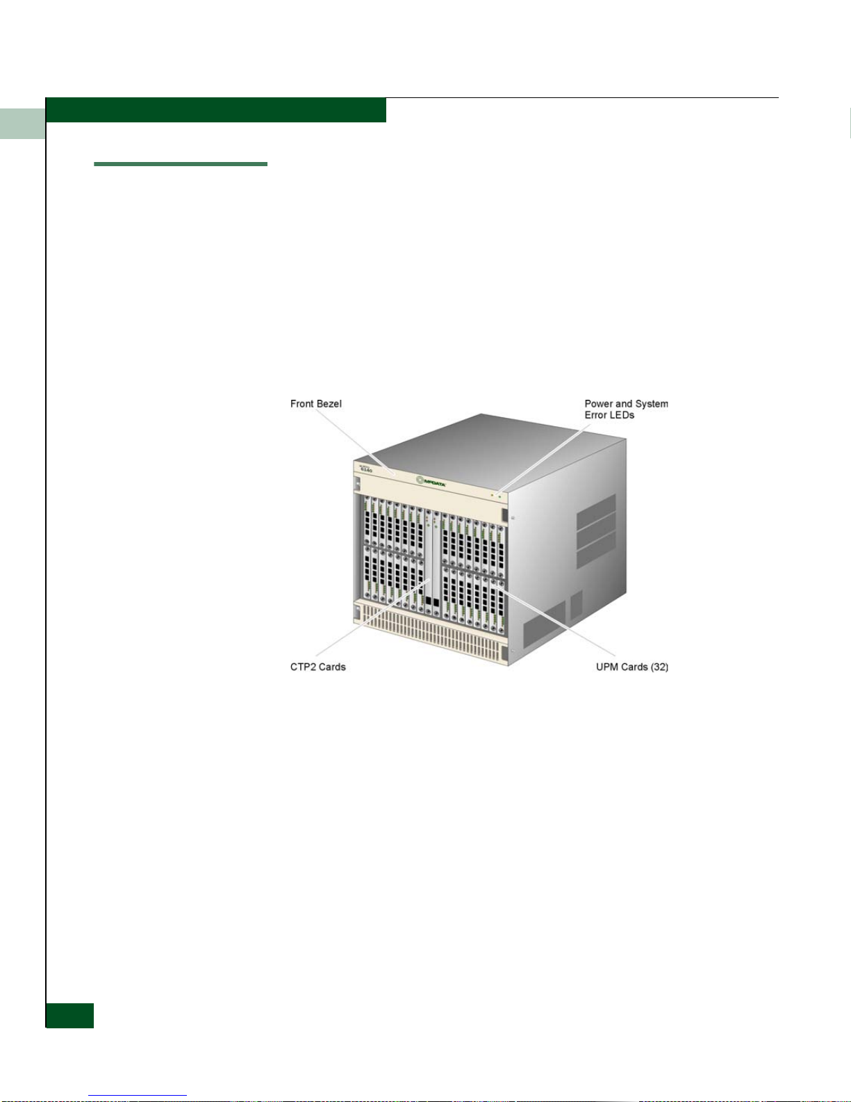
Director FRUs accessed from the front (Figure 1-2)includethe:
• Universal port module (UPM) cards (2 Gbps).
• 10 Gbps port module (XPM) cards.
• Control processor (CTP) cards.
Figure 1-2 Director FRUs (Front Access)
1-4
Intrepid® 6140 Director Installation a n d Service Manual
Director FRUs accessed from the rear (Figure 1-3)includethe:
•Fanmodules.
• Universal port module (UPM) cards (2 Gbps).
• 10 Gbps port module (XPM) cards.
• Serial crossbar (SBAR) assemblies.
• Power supplies.
•ACmodules.
• Power/System Error LED Assembly (not shown).
•Backplane(notshown).
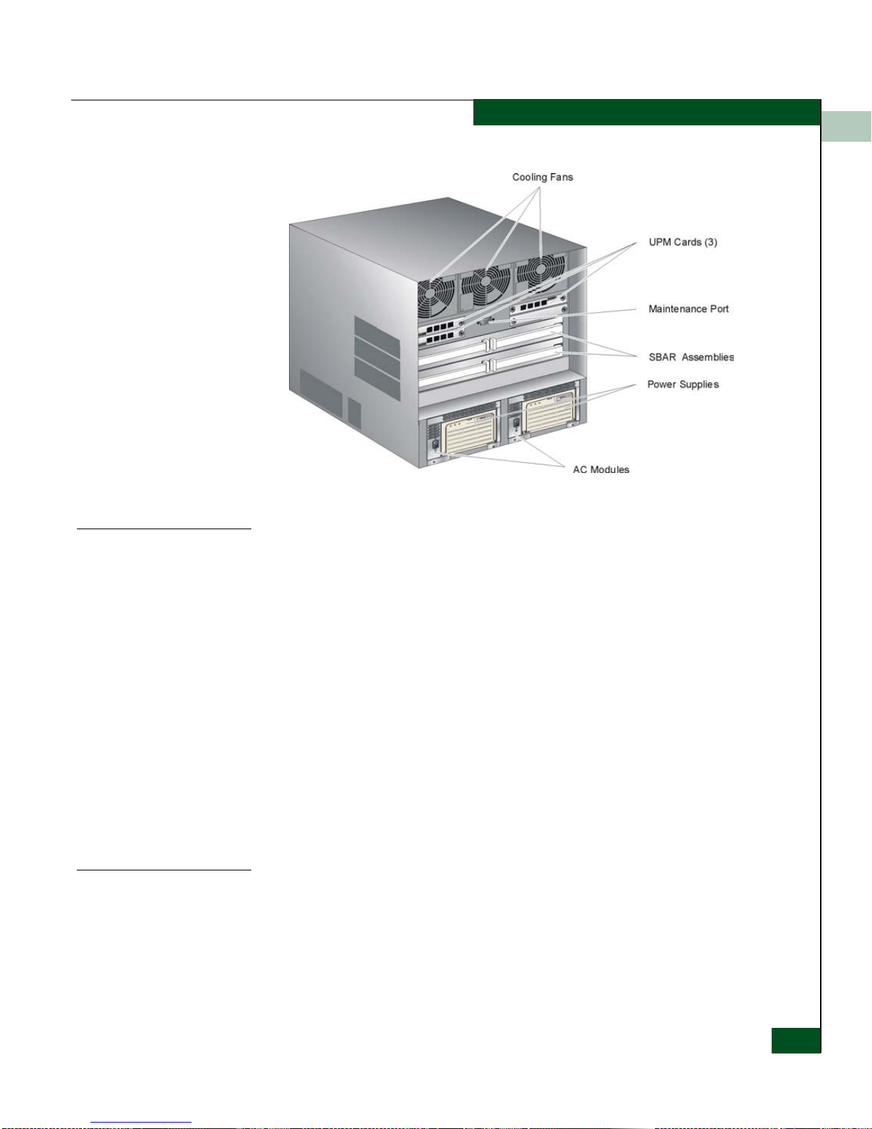
Figure 1-3 Director FRUs (Rear Access)
General Information
1
Power/System LED
Assembly
CTP Card
The bezel at the top front of the director includes an amber system
error light-emitting diode (LED) and a green power LED. These LEDs
are actuated and controlled by a Power/System LED Assembly
which is accessed from the rear of the director.
The power LED illuminates when the director is powered on and
operational. If the LED extinguishes, a facility power source,
alternating current (AC) power cord, or director power distribution
failure is indicated.
The system error LED illuminates when the director detects an event
requiring immediate operator attention, such as a FRU failure. The
LED remains illuminated as long as an event is active. The LED
extinguishes when the Clear System Error Light function is selected
from the Element Manager application. The LED blinks if unit
beaconing is enabled. An illuminated system error LED (indicating a
failure) takes precedence over unit beaconing.
The director is delivered with two CTP cards. The active CTP card
initializes and configuresthe director after power on and contains the
microprocessor and associated logic that coo rdinate director
operation.
The CTP card provides an initial machine load (IML) button and a
RESET button (recessed) on the faceplate.
Field-Replaceable Units
1-5

General Information
1
When the IML button is pressed, held for three seconds, and
released, the director performs an IML that reloads the firmware from
FLASH memory. This operation is not disruptive to Fibre Channel
traffic.
When the RESET button is pressed and held for three seconds, the
director performs a reset. A reset is disruptive and resets the:
• Microprocessor and functional logic for the CTP card and reloads
thefirmwarefromFLASHmemory.
• Ethernet LAN interface, causing the connection to the
management server to drop momentarily until the connection
automatically recovers.
• Ports,causing all Fibre Channel connections to drop momentarily
until the connections automatically recover. This causes attached
devices to log out and log back in, therefore data frames lost
during director reset must be retransmitted.
A reset should only be performed if a CTP card failure is indicated.
As a precaution, the RESET button is flush mounted to protect
against inadvertent activation.
Each CTP card also provides a 10/100 megabit per second (Mbps)
RJ-45 twisted pair connector on the faceplate that attaches to an
Ethernet local area network (LAN) to communicate with the
management server or a simple network management protocol
(SNMP) management station.
Each CTP card provides sys tem services processor (SSP) a nd
embedded port (EP) subsystems. The SSP subsystem runs director
applications and the underlying operating system, communicates
with director ports, and controls the RS-232 maintenance port and
10/100 Mbps Ethernet po rt. The EP subsystem provides Class F and
exception frame processing, and manages frame transmission to
and from the SBAR assembly. In addition, a CTP card provides
nonvolatile memory for storing firmware, director configuration
information, persistent operating parameters, and memory dump
files. Directorfirmware is upgradedconcurrently (without disrupting
operation).
The backup CTP card takes over operation if the active card fails.
Failover from a faulty card to the backup card is transparent to
attached devices.
Each card faceplate contains a green LED that illuminates if the card
is operational and active, and an amber LED that illuminates if the
1-6
Intrepid® 6140 Director Installation a n d Service Manual

General Information
card fails. Both LEDs areextinguished on an operational backup card.
The amber LED blinks if FRU beaconing is enabled.
1
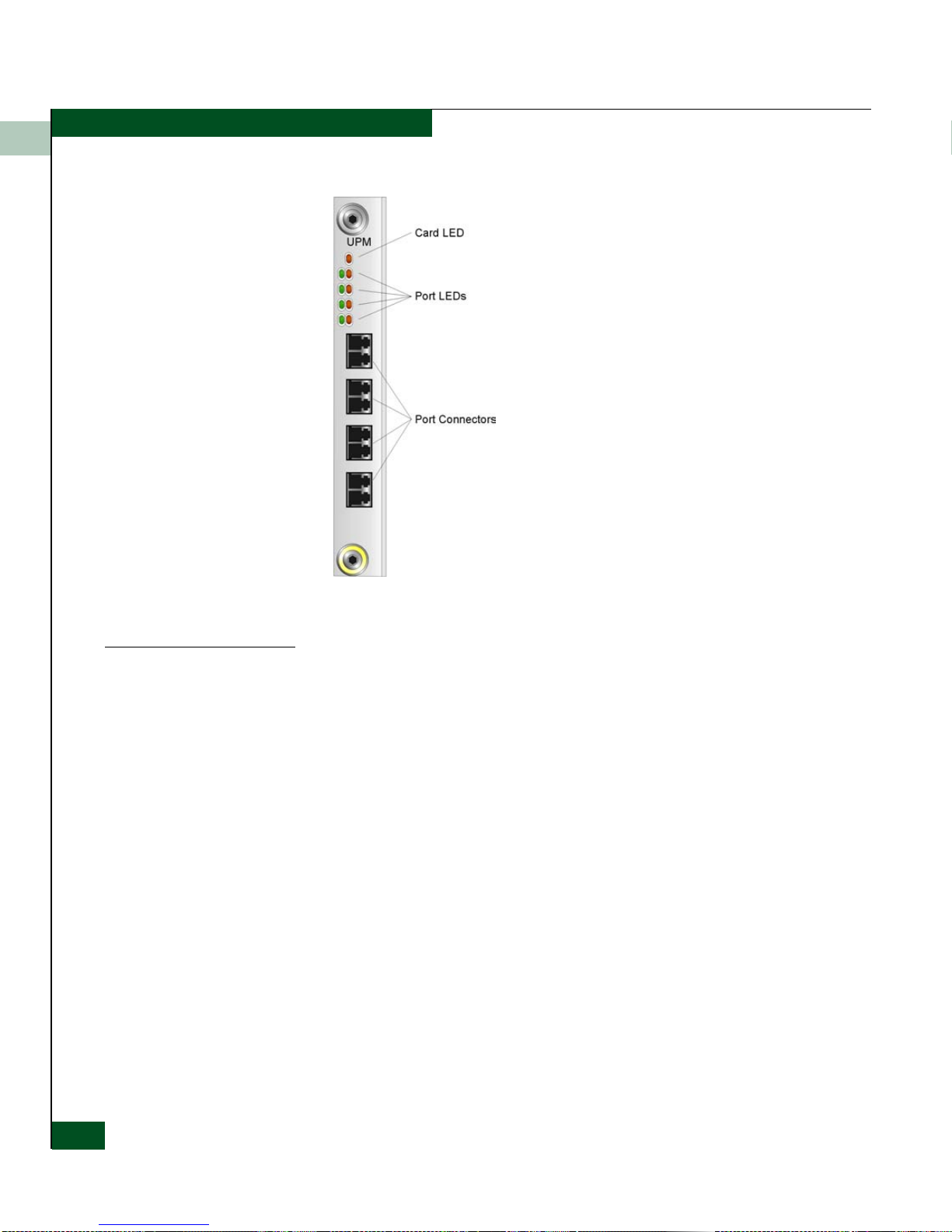
UPM Card
Each UPM card (Figure 1-4) provides four full-duplex generic ports
(G_Ports) that transmit or receive data at 2 gigabits per second
(Gbps). G_Port functionality depends on the type of cable
attachment. UPM cards use non-open fiber control (OFC) Class 1
laser transceivers that comply with Section 21 of the Code o f Federal
Regulations(CFR),Subpart(J)asofthedateofmanufacture.
The card faceplate contains:
• Four duplex LC connectors for attaching fiber-optic cables.
• AnamberLED(atthetopofthecard)thatilluminatesifanyport
fails or blinks if FRU beaconing is enabled.
• A bank of amber and green LEDs above the ports. One amber
LED and one green LED are associated w ith each port and
indicate port status as follows:
— The green LED illuminates (or blinks if there is active traffic)
and the amber LED extinguishes to indicate normal port
operation.
— The amber LED illuminates and the green LED extinguishes to
indicate a port failure.
— Both LEDs extinguish to indicate a port is operational but not
communicating with an N_Port (no cable attached, loss of
light, port blocked, or link recovery in process).
— The amber LED flashes and the green LED either remains on,
extinguishes, or flashes to indicate a port is beaconing or
running online diagnostics.
Field-Replaceable Units
1-7
General Information
1
XPM Card
Figure 1-4 UPM Card LEDs and Connectors
Each XPM card (Figure 1-5) provides one full-duplex generic port
(G_Port) that transmits or receives data at 10 gigabits per second
(Gbps). The card faceplate contains:
• One duplex LC connector for attaching fiber-optic cables.
• Amber and green LEDs that indicate port status similar to the
LEDs on the UPM cards (UPM Card on page 1-7).
1-8
Intrepid® 6140 Director Installation a n d Service Manual
 Loading...