

intrepid 350 WALKAROUND Owner's Manual

OWNER’S MANUAL
11700 SOUTH BELCHER ROAD
350
WALKAROUND
INTREPID POWERBOATS, INC.
LARGO, FL 33773
PHONE (727)548-1260
FAX (727)544-1796

TABLE OF CONTENTS
BOAT DATA
OWNER’S DATA A-1
BOAT DATA A-2
A WORD OF WELCOME A-3
WARRANTY INFORMATION
WARRANTY B-1
CUSTOMER’S RESPONSIBILITY B-4
CONTROL HELM
SPEED AND MANEUVERING CONTROLS C-1
ENGINE THROTTLE AND SHIFTER C-1
IGNITION SWITCHES C-2
STEERING C-3
BOAT AND ENGINE TRIM C-4
TRIM TAB SYSTEM C-4
ENGINE TILT AND TRIM C-6
ENGINE INSTRUMENTATION C-7
THE IMPORTANCE OF ENGINE INSTRUMENTATION C-7
BASIC ENGINE INSTRUMENTATION C-7
TACHOMETER C-7
VOLTMETER C-7
FUEL GAUGE C-7
TRIM GAUGE C-7
HOURMETER C-8
ENGINE MANUFACTURER SUPPLIED INSTRUMENTATION C-8
ELECTRICAL SYSTEM CONTROL C-9
BATTERY SWITCH PANEL OPERATION C-10
NAVIGATIONAL SYSTEMS C-11
COMPASS C-11
ELECTRONICS C-11
ACCESSORIES
HELM DC PANEL D-1
SWITCH PANEL POWER D-1
NAVIGATION LIGHTS D-2
NAVIGATION LIGHTS D-2
ANCHOR LIGHT D-2
TRIM TABS D-3
BAITWELL PUMP (WITHOUT OPTIONAL GENERATOR) D-3
BAITWELL PUMP (WITH OPTIONAL GENERATOR) D-5
FRESH WATER SYSTEM D-7
FISH BOX MACERATOR D-8
FISH BOX MACERATOR SYSTEMS D-10
SALTWATER PUMP D-12
ELECTRONICS D-13
BILGE PUMP SYSTEMS D-13

ACCESSORIES (continued)
BILGE PUMP #1 D-13
BILGE PUMP #2 D-14
CABIN BILGE PUMP D-14
COCKPIT LIGHTS D-16
ACCESSORY # 1 D-16
ACCESSORY # 2 D-17
OVERHEAD LIGHT OPTION D-17
ACCESSORY # 3 D-17
SPREADER LIGHT OPTION D-18
ACCESSORY # 4 D-18
ACCESSORY # 5 D-19
COCKPIT REFRIGERATOR D-19
ACCESSORY # 6 D-19
ELECTRIC HELM SEAT OPTION D-19
ACCESSORY #7 D-20
CABIN DC PANEL D-20
CABIN BILGE PUMP D-20
SUMP PUMP D-21
REFRIGERATOR D-21
WASTE SYSTEM D-22
HEAD LIGHT D-25
CABIN LIGHTS D-26
OVERHEAD LIGHTS D-27
FUEL SYSTEM
FUEL SYSTEM E-1
FUEL TANK PICKUPS E-1
FUEL FILTERS E-2
SHUTOFF VALVES E-2
PRIMER BULBS E-3
TANK FILL E-3
TANK VENT E-3
FUEL LEVEL SENDER E-3
BONDING E-4
SYSTEM INSPECTION E-4
DECK HARDWARE
ANCHOR ROLLER F-1
MOORING CLEATS F-2
ANCHOR LOCKER F-2
CABIN HATCH F-2
COCKPIT SCUPPERS F-2
OIL TANK FILLS F-2
BOW AND STERN EYES F-3
TOW EYE OPTION F-3
THRU HULL LOCATIONS
THRU HULL LOCATIONS G-1

120VAC ACCESSORIES
120VAC ELECTRICAL SYSTEM H-1
120VAC SOURCE H-3
120VAC DISTRIBUTION H-3
AC DISTRIBUTION PANEL H-3
GROUNDED NUETRAL BUS BAR H-5
GROUNDING BOND BUS BAR H-5
GALVANIC ISOLATOR H-6
120VAC ACCESSORIES H-6
AC OUTLETS H-6
MICROWAVE H-6
BATTERY CHARGER H-6
AIR CONDITIONING OPTION H-7
WATER HEATER H-8
REFRIGERATOR H-9
SPARE H-10
OPTIONAL COCKPIT COOLER H-10
BONDING H-11
OPTIONAL SYSTEMS
WINDLASS SYSTEM
DC DISTRIBUTION I-1
WINDLASS CONTROL I-1
WINDLASS OPERATION I-2
GENERATOR SYSTEM J-1
DC DISTRIBUTION J-2
AC DISTRIBUTION J-2
FUEL SYSTEM J-4
RAW WATER J-5
EXHAUST J-6
GENERATOR CONTROLS J-6
ACCESSORIES J-7
HALON FIRE EXTINGUISHER J-7
CO MONITOR J-7
BOW THRUSTER SYSTEM
DC DISTRIBUTION K-1
THRUSTER CONTROL K-2
THRUSTER OPERATION K-2
OPERATING YOUR INTREPID
OPERATING YOUR INTREPID L-1
STARTING THE ENGINES L-1
RUNNING YOUR INTREPID L-1
PERFORMANCE L-2
ENGINE EFFICIENCY L-2
ATMOSPHERIC CONDITIONS L-2
PERSONAL EQUIPMENT AND ACCESSORIES L-2
MARINE GROWTH L-2
BILGE WATER L-2

PROPELLERS L-2
MAINTAINING YOUR INTREPID
MAINTAINING YOUR INTREPID M-1
DAILY / WEEKLY MAINTENANCE M-1
100 HOURS OR 60 DAYS M-1
EXTERIOR M-1
INTERIOR M-2
BILGE AREAS M-2
CONTROL HELM M-2
FIBERGLASS AND GELCOAT CARE M-2
LEAVING YOUR INTREPID
LEAVING YOUR INTREPID N-1
SHORT TERM N-1
LONG TERM N-1
STORING N-1
DRY STORAGE N-1
WET STORAGE N-1
LAUNCHING YOUR INTREPID N-2
PRE LAUNCH N-2
AFTER LAUNCH N-2
RULES OF THE ROAD
RULES OF THE ROAD O-1

A WORD OF WELCOME
We are pleased that you have chosen Intrepid.
Intrepid’s unique step-lift bottom design will give you excellent performance and many years of
boating pleasure.
The step-lift hull is a state-of-the-art design that reduces the wetted surface of the hull bottom,
which means less drag and higher performance.
Your Intrepid is built of the finest, most modern materials and is manufactured under rigid quality
controls. The hull is constructed of high-impact hand laid up multi-laminate fiberglass. Your boat
comes to you as the most thoroughly tested and trouble free boat on the market today. Each boat
is thoroughly sea-trialed before delivery.
While durable in its construction, your Intrepid will benefit from reasonable care, maintenance and
adjustments. Repairs may be required from time to time with certain components as with all
mechanical items. This manual has been specially prepared for your particular model to guide
you in keeping it in the best possible condition.
To fully enjoy your Intrepid you should understand it completely and we suggest you read this
manual thoroughly. If any points arise that you do not completely understand, your dealer will be
able to help you.
It is also recommended that you read all the associated instruction manuals for the components
installed on your Intrepid. These manuals are included in your Owner’s Pack.
When your Intrepid requires service, contact your dealer. They are there to assist you in every
way possible.
We wish you many years of safe and pleasurable boating with your new Intrepid.
A-3

WARRANTY
Below is a copy of the Warranty statement that you signed at the closing of your boat:
Intrepid Powerboats, Inc. is proud of its heritage and reputation for producing products with high
standards of quality and workmanship. Product excellence serves as the cornerstone of our
commitment to customer satisfaction. Intrepid Powerboats, Inc.’s Limited Warranty (“Warranty”) is
your assurance of this commitment. This warranty provides you with protection against certain
repair expenses resulting from defects in materials or workmanship. When maintained and
utilized in the prescribed manner, you can count on your Intrepid boat to provide reliable service.
This Warranty provides you with specific coverage and notes your responsibilities in maintaining
and operating your Intrepid boat. Please take time to read and become familiar with this
Warranty.
WARRANTY PERIOD. For the period of three (3) years from the date of first purchase at retail
(except for a defect in the paint or gelcoat finish which shall be limited to ninety days from the
date of first purchase at retail) Intrepid Powerboats, Inc. warrants to the first purchaser at retail
that the Intrepid Boat shall be free from defects in material or workmanship, subject to the
following conditions, exclusions and provisions.
CONDITIONS OF WARRANTY. As a condition of Intrepid Powerboat, Inc.’s obligations under
this Warranty the first purchaser at retail shall:
1. Within ten (10) days of the date of sale, complete and mail to Intrepid Powerboats, Inc. the
Owner’s Warranty Registration attached hereto:
2. Make any claim under this Warranty, and any notification and/or communications in
connection therewith, to and through the authorized Intrepid Powerboats, Inc. dealer who
sold the Intrepid Boat to the first purchaser at retail, or if such authorized dealer is not readily
available, to and through another authorized Intrepid Powerboats, Inc. dealer:
3. Upon request by Intrepid Powerboats, Inc., promptly return the Intrepid Powerboat to Intrepid
Powerboats, Inc. transportation charges prepaid, and:
4. Not permit any repair and/or replacement services covered under this Warranty to be
preformed by any unauthorized party.
EXCLUSIONS FROM WARRANTY. This warranty shall not apply to:
1. Any Intrepid Boat that has been used at any time for commercial purposes, including, but not
limited to, use in or for the production of revenue or income;
2. Any Intrepid Boat, which has been subject to abuse or neglect in use or service, including,
but not limited to careless or improper hauling, loading, use or operation (a) for racing
purposes, (b) contrary to load or horsepower capacity recommended by Intrepid Powerboats,
Inc., (c) contrary to Intrepid Powerboats, Inc. operation and maintenance instructions, or (d)
in connection with accessories not recommended by Intrepid Powerboats, Inc.;
3. Any observable defect in windshield, upholstery material or convertible top discovered after
deliver to the first purchaser at retail;
4. Any defect caused by, resulting from or in connection with installation of any engine by any
party other than Intrepid Powerboats, Inc.;
5. Engines, outdrives, controls, propellers, pumps, trim tabs, breakers, lights, and other
products not manufactured by Intrepid Powerboats, Inc.; provided, however to the extent
possible, Intrepid Powerboats, Inc. shall pass on to the first purchaser at retail the warranties
of the manufacturers of such items;
6. Any repair or replacement made necessary by normal wear and tear;
7. Any party other than the first purchaser at retail; and
8. Any incidental or consequential damages arising out of , or as a result of, any defect part or
parts, including, but not limited to, loss of use.
B-1

OTHER PROVISIONS OF THIS WARRANTY
1. No Intrepid Powerboats, Inc. dealer or any other party is or shall be authorized to assume,
create, or amend any obligation or responsibility, on behalf of or in the name of Intrepid
Powerboats, Inc. or to bind Intrepid Powerboats, Inc. in any manner in connection with this
Warranty, unless specifically authorized to do so in writing by Intrepid Powerboats, Inc. and
such written authorization shall only be effective for the claim and to the extent expressly
specified therein.
2. Intrepid Powerboats, Inc. reserves the right to change the design, materials, and equipment
of Intrepid Boats without assuming any responsibility or obligation to incorporate such
changes in the repair or replacement of or to Intrepid Boats, pursuant to this Warranty, which
were manufactured prior to any such changes.
EXCLUSIVE REMEDY OF WARRANTY. As the original purchaser’s sole and exclusive remedy
under this Warranty, Intrepid Powerboats, Inc. will repair or replace without charge any part or
parts covered under this Warranty, which, in the sole discretion of Intrepid Powerboats, Inc. or an
authorized dealer of Intrepid Powerboats, Inc., is found to be defective in material and
workmanship.
Intrepid Powerboats, Inc. makes no other warranty of any kind. This Warranty displaces and is in
lieu of all other express or implied warranties of any kind regarding Intrepid Powerboats, Inc.
products, including any implied warranties of merchantability and fitness for a particular purpose
which are hereby disclaimed and negated in all respects.
This Warranty gives you specific rights, you may also have other rights which vary from state to
state.
B-2

WARRANTY ADDENDUM
NOTICE TO FIRST PURCHASER FROM INTREPID POWERBOATS, INC.
PURCHASER NAME:
ADDRESS:
CITY:
ZIP:
BOAT S/N:
ENGINE MFG:
S/N:
S/N:
PURCHASE DATE:
I,
item number 5 under “Exclusions from Warranty” and fully understand that if and when there is
any warranty, or service needed for the outboard or inboard motors, I must make arrangements
with my local factory authorized service center, as INTREPID is not an authorized service center
for motors or related parts.
The balance of number 5 will be handled by Intrepid Boats through the warranty extended by that
specific manufacturer.
All Yamaha engines rigged by Intrepid Powerboats use a custom rig tube receiver at the engine
that does not allow the tube to fall out as other rig tube receivers do.
It is most important that when the engines are trimmed all the way up in the out of water position,
that the engines must be turned hard over to port or starboard (preferable port), before trimming
them up so that you will not kink the rigging tube.
On triple engine installations, care must be taken not to turn the engines hard over prior to tilting
as damage to engine cowling may occur.
SIGNED:
DATE:
have read the INTREPID Limited Warranty and specifically
B-3

CUSTOMER’S RESPONSIBILITY
Read your warranty certificate carefully and promptly mail in the warranty registration with all the
requested information.
The warranty is specific as to what is covered by warranty and how to obtain repair.
It is important to realize that there is a difference between warranty work, routine maintenance
and damage caused by misuse or negligence.
If you experience a problem with your Intrepid or any of the factory installed components, contact
the Intrepid factory with a complete description of what is occurring for assistance. We will then
advise you of the quickest and best way to resolve the problem.
The engine(s) are covered separately under warranty by the Engine Manufacturer. Any engine
warranty or service work must be performed by an Engine Manufacturer’s authorized service
center.
Do not operate your Intrepid or any system or component until you have read and understand this
manual or the manuals supplied by equipment suppliers. Supplied equipment manuals are
included in your Owner’s Pack.
The delivering representative or dealer should familiarize you with the operation and handling of
your Intrepid so that you will have a complete understanding of your boat. If you have any
questions regarding your Intrepid or its operation, contact us and we will answer all questions.
B-4
CONTROL HELM
The Helm on your Intrepid is the control and monitor center for the engine and electrical, steering,
and navigational systems installed on your boat.
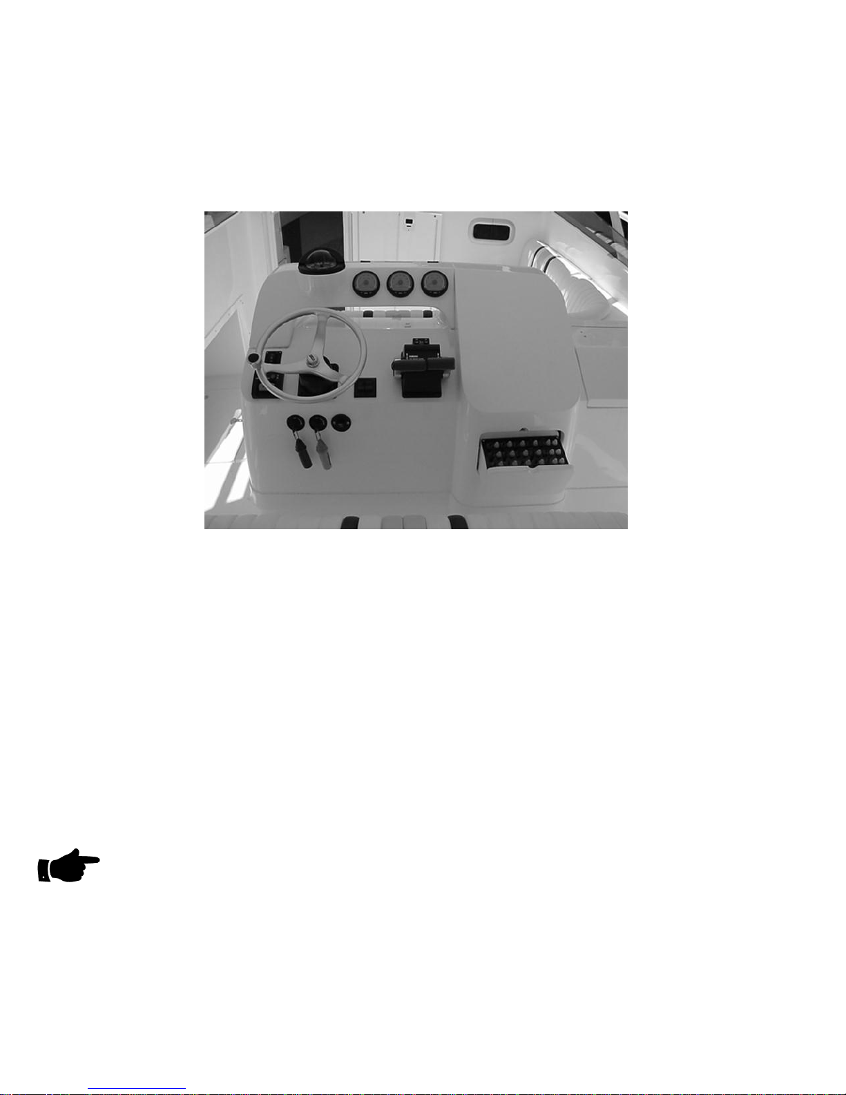
THE CONTROL HELM
(TWIN ENGINE MERCURY OPTIMAX WITH SMARTCRAFT GAUGE PACKAGE SHOWN)
SPEED AND MANEUVERING CONTROLS
Located on the helm are all the controls necessary to control your engine and maneuvering
functions. These controls include:
1. Engine Throttle & Forward/Reverse Controls
2. Ignition/Start Switches
3. Steering System
4. Boat & Engine Trim
1. Engine Throttle / Shift Control (Outboard)
Throttle and Shift controls are installed on the starboard side of the steering helm. They are pushpull controls and are connected to the engine throttle and shift mechanisms through push-pull
cables.
NOTE
Refer to the Engine Control manufacturer’s manual for proper operation and maintenance of the
Engine Control system. This manual is included in your Owner’s packet.
The Shift Control shifts the engine in the same direction the lever is moved, forward to go forward
and aft to move backwards.
C-1
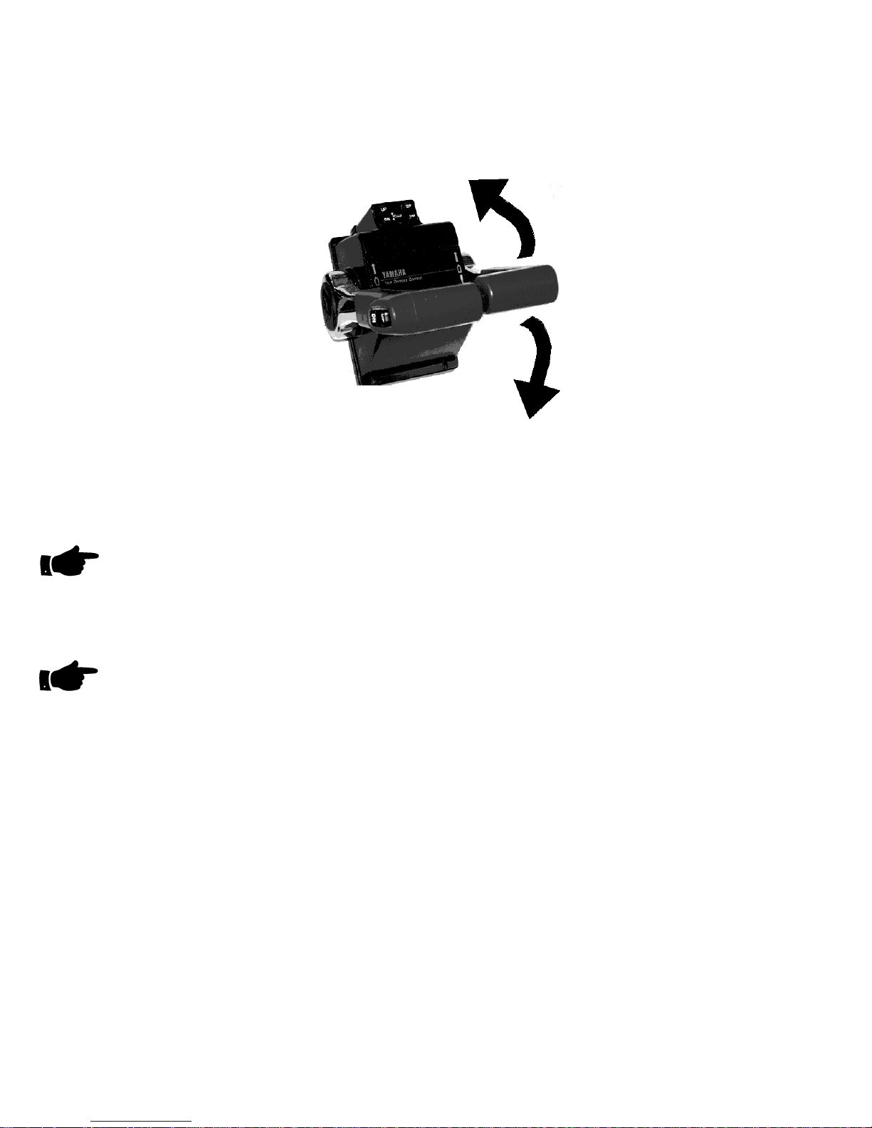
The Throttle Control controls the engine speed or RPM by pushing the levers forward to increase
speed and pulling the lever back to decrease speed in forward gear.
TWIN ENGINE THROTTLE / SHIFT CONTROLS
NOTE
It is recommended that you check for proper throw of the shift mechanism when you first take
delivery and periodically to ensure full throw into forward and reverse. If the gears are not fully
engaged while running, extensive damage can occur which is not covered under the engine
manufacturer's warranty. If you find your controls are not adjusted correctly, contact your dealer
immediately to have them adjusted.
NOTE
Avoid high RPM operation out of gear in the same manner you would with your personal
automobile.
2. Ignition Switches
The Ignition Switches are provided by the Engine Manufacturer. Refer to the information on the
operation of the Ignition Switch that is located in your Owner’s Pack.
The Ignition Switches provides you with the ability to:
1. Energize the engine electrical system
2. Energize the engine instrumentation
3. Crank the engine.
4. Choke the engine during starting
5. Turning off the engines, engine electrical systems, and instrumentation.
C-2
IGNITION ON
ENGINE AND
IGNITION OFF
YAMAHA
KILL SWITCH
AND LANYARD
ENGINE START
PUSH KEY TO
CHOKE
YAMAHA IGNITION SWITCH
NOTE
The Lanyard connected to the Engine Kill Switch should be attached to the boat’s helmsman
whenever underway. If the helmsman is thrown or rolled away from the helm, the Lanyard will
unclip from the Engine Kill Switch and shutdown the engines.
If extra Ignition Switch keys are required, contact Intrepid Powerboats. Key numbers can be
found in this Owner’s Manual.
3. STEERING SYSTEM
The hydraulic steering system transmits power from the steering wheel to the steering ram
mounted on the engines to control the turning of the engines. The system gives instant steering
response to the engines to control the direction of the boat while under way.
STEERING CYLINDER
TEES
HYDRAULIC
LINES
STEERING HELM
SPLASHWELL
FITTINGS
HYDRAULIC STEERING SYSTEM DIAGRAM
NOTE
Refer to the Steering Control manufacturer’s manual for proper operation and maintenance of the
teering system. This manual is included in your Owner’s packet. S
The helm unit under the steering wheel contains the hydraulic fluid that supplies the complete
steering system. Periodic checks of the fluid level should be performed to insure an adequate
Supply is always available to prevent air from entering the system and causing a degradation or
loss of steering.
C-3

The steering system uses hydraulic fluids as outlined in literature for the steering supplied in the
Owner’s packet.
NOTE
The Steering Helm is the hydraulic pump for the system. The direction that the helm is turned
controls check valves in the helm, which in turn determines the direction of flow to the steering
cylinders. When refilling the helm with hydraulic fluid care must be taken to ensure no small
particles of debris enters the system. Debris can affect the operation of the check valves, which
may mean a degradation of or loss of steering capability.
4. BOAT & ENGINE TRIM
TRIM TAB SYSTEM
The Trim Tab System is operated with the switches on the Control Helm. These switches control
the direction and amount the transom mounted trim tabs move.
Power to these switches is supplied from the "TRIM TAB" switch and re-settable circuit breaker
located on the switch panel.
This electric-hydraulically-operated system is used to trim the running attitude of the boat while
under way. If used properly, the trim tabs will aid in trimming the boat in fore and aft and side to
side position, providing a better view for the helmsman and allowing an overall smoother ride and
with increased efficiency.
The operator should be aware that each trim tab does not operate as a unit, but are individually
controlled to allow trimming to correct a listing position while under way.
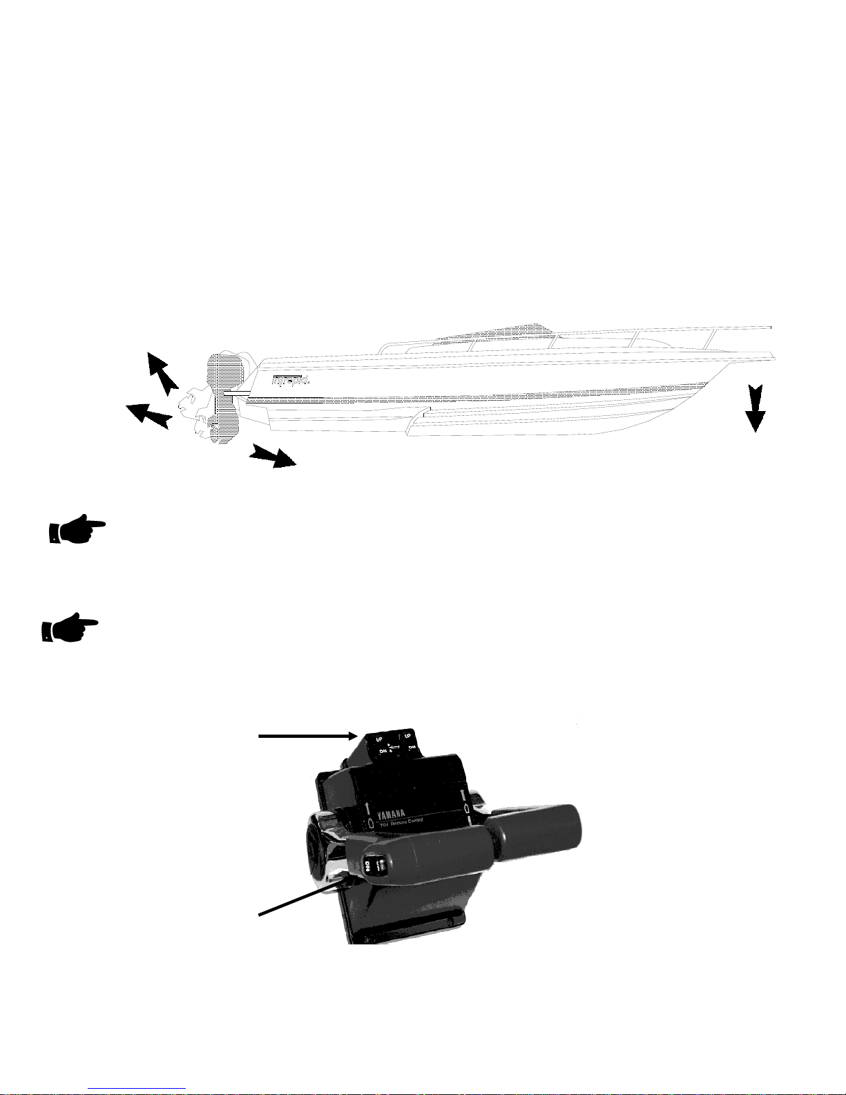
The double rocker switch located on the helm console actuates the trim tabs. Depressing the top
of the switches lowers the tabs, which causes the bow of the boat to go down while underway.
Depressing the bottom of the switches to the "UP" position allows the bow to rise.
BOW
STERN
LOWERS
RISES
TABS
DOWN
The speed of your boat and conditions of the water will determine the extent of lowering your trim
tabs.
The trim tabs should always be in the "UP" position when dockside and during slow operation
such as docking or slow trolling.
Trim tab position in a following sea must be up. If the trim tabs are down excessively, it can affect
handling characteristics and decrease steering ability and response.
C-4
NOTE
When backing down hard such as can occur in fishing, the extreme force on the tabs from the
water can damage the trim tabs or cylinders if they are not in the full "UP" position
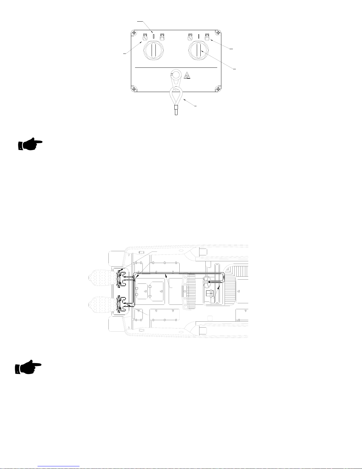
PORT TRIM TAB
& CYLINDER
ELECTRICAL
HARNESS
TRIM TAB
PUMP
TRIM TAB
SWITCH
STBD TRIM TAB
& CYLINDER
.
TRIM TAB SYSTEM DIAGRAM - TYPICAL
The pump/reservoir for the trim tabs is located in aft center bilge area, under the aft center cockpit
hatch. Check the fluid level in the reservoir before operating the trim tabs. The hydraulic fluid level
can be seen through the translucent reservoir container mounted on the bottom of the pump.
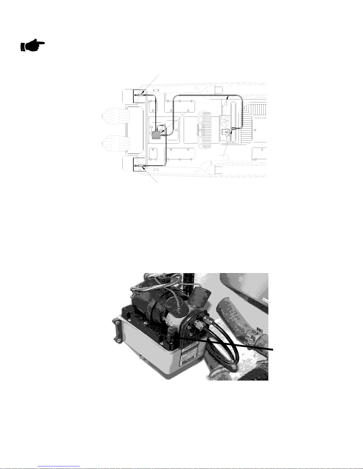
Hydromatic transmission fluid is used in this system to actuate the cylinders. If addition of fluid is
necessary, remove the screw in the center of the top cover and lift the cover off. The small plug is
removed from the corner of the pump / reservoir and fluid is added using a small funnel to bring
fluid level to correct height.
C-5
PUMP RESERVIOR FILL
TRIM TAB PUMP
Consult the trim tab owner’s manual supplied in your owner’s packet for complete instructions on
the operation and maintenance of the units.
ENGINE TRIM & TILT
The engines Tilt/Trim system is provided by the Engine Manufacturer. Refer to the information on
the operation of the Tilt/Trim system that is located in your Owner’s Pack.
The Trim Buttons next to Engine Throttle/Transmission Control operates the system. Trimming
the engine DOWN has the affect of lowering the bow.
ENGINE TILT
POSITION
ENGINE UP
POSITION
NOTE
In normal conditions only a few seconds of DOWN Trim from the full UP position is necessary.
The Trim button also controls the Tilt position. The engine’s electrical system must be on to tilt the
engine from the Helm.
NOTE
When tilting an engine, observe the rigging tubes from the engine to the boat. If tilting the engine
causes a tight bend in one of these tubes, it may be necessary to steer the engine one turn in a
direction to relieve the tight bend.
INDIVIDUAL ENG TRIM
BOW DOWN IN ENGINE
DOWN POSITION
ENGINE DOWN
POSITION
SIMALTANEOUS ENG TRIM
C-6
ENGINE TRIM/TILT SWITCHES

ENGINE INSTRUMENTATION
1. THE IMPORTANCE OF ENGINE INSTRUMENTATION
To avoid the possibility of mechanical damage to your Engine basic instrumentation for each
Engine is provided on your Intrepid. Unless specified at the time an Intrepid was ordered from the
factory, your boat will be fitted with instrumentation provided by the Engine Manufacturer.
The operator of this boat should become accustomed to checking the instrumentation frequently
when running and particularly when first starting the Engine.
Engine instrumentation gives indications as to what is happening to the engines while they are
being operated. It is important that you become familiar with the appropriate reading for each
instrument. This information is provided by the Engine Manufacturer and is located in your
Owner’s Packet.
Power is provided to an engine’s instrumentation by that engine’s electrical system. The engine’s
Ignition Switch must be on for the instruments to operate.
2. BASIC ENGINE INSTRUMENTATION
TACHOMETER
This instrument provides a reading of Revolutions Per Minute (RPM) of the engine. There is no
set correlation of RPM’s to the speed of the boat. Speeds at various RPM’s should be determined
by using a Speedometer or an electronic device.
VOLTMETER
This instrument monitor’s the amount of charge available in the engine battery. A low voltage
reading when the engine is not running indicates that the battery is not at full charge. A voltage
indication of 13 to 15 volts when the engine is running indicates that the battery is charging.
FUEL GAUGE
The electric fuel gauge indicates the amount of fuel remaining in the fuel tank in terms of
percentage of tank capacity.
The fuel gauge provides a convenient but approximate indication of remaining fuel. Safe
operation of this boat requires filling the fuel tank after each use and becoming familiar with fuel
usage under various conditions.
NOTE
If your Intrepid is equipped with an auxiliary Fuel Tank but has only one Fuel Gauge, your boat
has been fitted with a Main Tank / Auxiliary Tank Selector switch located on your console.
Selecting MAIN will provide a fuel level reading for the Main Tank and an AUX selection will
provide a fuel level reading on the Auxiliary Tank.
NOTE
The fuel senders mounted into the tanks are located under access plates in the cockpit deck.
These senders control the electric gauge on the helm and incorporate a mechanical indication of
Fuel Level on top of each sender.
TRIM GAUGE
The trim gauge provides an indication of the amount an engine is trimmed up or down. Monitoring
this gauge will provide you with the ability to set the amount of engine trim for optimum
performance.
C-7

Hour Meter (Optional)
This meter registers the amount of time in hours that the engine’s ignition system has been on. It
is activated when the Ignition Switch is turned ON. If the hour meter is to be replaced, note the
hours on the old Hour Meter. This figure must be added to the hours shown on the new Hour
Meter to determine the amount of total hours an engine has run.
3. ENGINE MANUFACTURER SUPPLIED INSTRUMENTATION
Unless specifically requested at the time a boat was ordered Intrepid has installed
instrumentation that is provided by the Engine Manufacturer.
Information on the use of Engine Manufacturer Instrumentation and the range of normal operating
indications is found in the Engine Owners Manual. This manual is located in your Owner’s Pack.
TACHOMETER
DIGITAL TACHOMETER
HOUR METER
POWER TRIM ANGLE
ENGINE TEMPERATURE
BATTRY VOLTAGE
WATER PRESSURE
SMART TACH
MERCURY SMARTCRAFT INSTRUMENTATION
TRIM GAUGE
TACHOMETER
ENGINE ALARMS
FUEL GALLONS/HOUR
TRIP
OPTIONAL FUEL MANAGEMENT
YAMAHA MULTIFUNCTION INSTRUMENTATION
CLOCK & TEMPERATURE
FUEL TANK LEVEL (S)
FUEL FLOW
DIGITAL SPEEDOMETER
BAROMETER READING
SPEEDOMETER
FUEL GAUGE
SPEED DISPLAY
TRIP & TIME
VOLT METER
SPEEDOMETER
OIL TANK LEVEL(S)
FUEL ECONOMY
FUEL RANGE
TRIP ODOMETER
C-8
ELECTRICAL SYSTEM CONTROL
DC Electrical power is supplied to the Engine electrical system and the boat’s accessories by the
batteries. This power is controlled by Battery Disconnect Switches. The Batteries and Battery
Switches are located @ or under the Helm.
Proper use of the Battery Switches will help lengthen battery life and help provide optimum
charge of the batteries.
If your boat is equipped with optional accessories (Bow Thruster, or Generator, for example)
there will be additional switches on your boat. Specifics on the use of these switches can be
found in the section of this Owner’s Manual that pertains to that accessory.
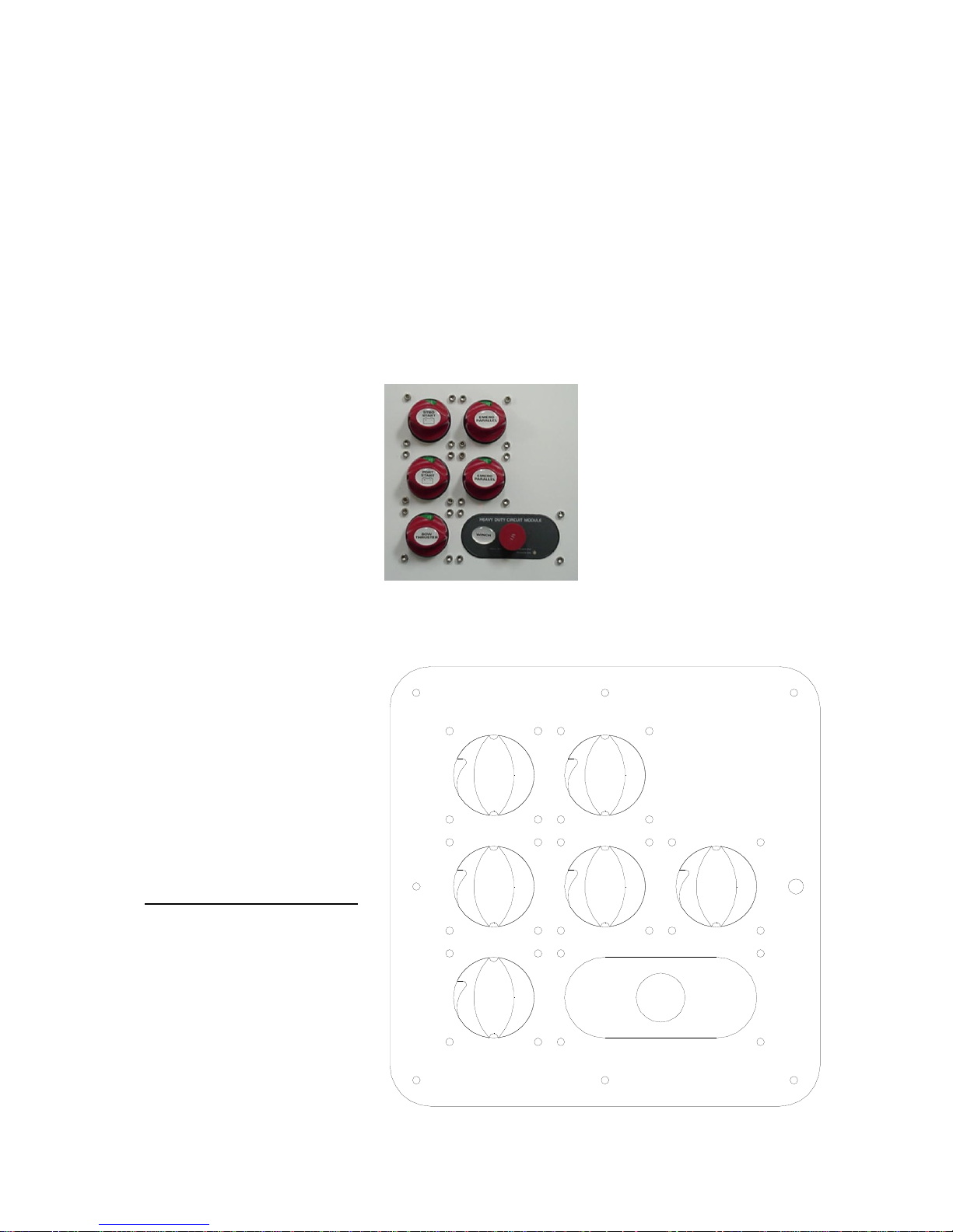
The battery disconnect switches are located on the side of the helm console.
(SHOWN W/BOW THRUSTER & WINDLASS
ALL BATTERIES OFF
OPTIONS SHOWN INCLUDE:
BOW THRUSTER
WINDLASS
GENERATOR
BATTERY SWITCH PANEL
OPTION )
ALL SWITCHES IN ON POSITION
STBD
START
PORT
START
BOW
THRUSTER
WINCH
EMERG
PARALLEL
GEN
EMERG
PARALLEL
135
START
C-9
`
STBD
START
PORT
START
BOW
THRUSTER
NOR ERY
MAL OPERATION BATT
EMERG
EMERG
WINCH
PARALLEL
GEN
PARALLEL
START
135
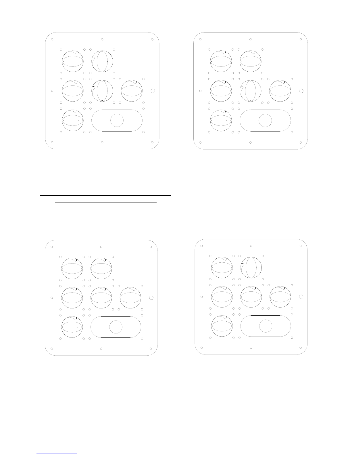
SWITCH POSITIONS
ALL BATTERIES ON WITH
PARALLEL SWITCHES OFF
EMERGENCY PARALLEL SWITCHES MUST
REMAIN “OFF” DURING NORMAL
OPERATION
STBD
START
PORT
START
BOW
THRUSTER
EMERG
PARALLEL
EMERG
PARALLEL
WINCH
135
GEN
START
STBD START PARALLEL
CIRCUIT TURNED ON
AUX. BATTERY WILL BE PLACED
IN SERIES WITH STBD START
BATTERY TO INCREASE POWER
AVAILABLE FOR ENGINE
CRANKING
ONCE ENGINE IS RUNNING RETURN EMERGENCY PARALLEL SWITCH TO OFF POSITION
STBD
START
PORT
START
BOW
THRUSTER
EMERG
PARALLEL
EMERG
PARALLEL
WINCH
135
GEN
START
STBD & PORT PARALLEL CIRCUIT
TURNED ON
AUX. BATTERY WILL BE PLACED IN
SERIES WITH BOTH THE STBD AND
THE PORT START BATTERY TO
INCREASE POWER AVAILABLE FOR
ENGINE CRANKING
STBD
START
PORT
START
BOW
THRUSTER
EMERG
PARALLEL
EMERG
PARALLEL
WINCH
GEN
START
135
PORT START PARALLEL
CIRCUIT TURNED ON
AUX. BATTERY WILL BE PLACED
IN SERIES WITH PORT START
BATTERY TO INCREASE POWER
AVAILABLE FOR ENGINE
CRANKING
ONCE ENGINE IS RUNNING RETURN EMERGENCY PARALLEL SWITCH TO OFF POSITION
C-10

NOTE
A battery will be charged by the Alternator of the engine it is connected to or the Battery Charger
regardless of the position of its battery switch. The Auxiliary battery of the battery system will be
charged by the alternator of an engine or by the Battery Charger.
NOTE
When all the batteries are disconnected from the electrical system by turning all the switches
OFF, all Engines and Accessories are inoperative with the exception of the Automatic Bilge Pump
circuits
CAUTION
Never disconnect a running engine from the batteries. Ensure that at least one battery is
connected to a running engine at all times. Failure to do so may cause damage to the diodes of a
disconnected running engine’s alternator.
NAVIGATIONAL SYSTEMS
1. COMPASS
Your Intrepid may be supplied with an optional compass.
The compass is located on the Control Helm just forward of the steering helm. Compass internal
lighting is controlled by the NAV/ANCHOR Light Switch located on the Control Helm Switch
Panel.
The compass was calibrated at the compass manufacturer’s facility. Intrepid makes no attempt to
further calibrate (swing) the compass.
To ensure accurate compass readings, the owner must calibrate the compass to eliminate
deviations caused by the geographical area that the boat will operate in and after the owner has
installed any metal or electrical/electronic equipment on the Control Helm.
Information on calibrating the compass is included in the literature provided by the compass
manufacturer. This literature can be found in your Owner Pack.
2. ELECTRONICS
Your Intrepid is provided with a switch and a 30 AMP circuit breaker on the Control Helm Switch
Panel. This ON/OFF switch supplies a small 4 position terminal block located on the underside of
the Control Helm face. Ground is also provided at this small terminal block. Any owner-installed
electronics should be powered from this terminal block.
NOTE
When installing electronics, always use the current protection devices supplied or required by the
manufacturer of the electronics. These over current protection devices should be connected to
the 12AWG Red wire on this terminal block.
C-11

16 RED
16 BLK
12 BLK
12 RED
TO COMPASS AND
GAUGE LIGHTS
TO ELECTRONICS NEGATIVE
TO ELECTRONICS POSITIVE
A second Electronics power supply is provided for electronics added to a Hard or T-Top If a top
was installed by Intrepid this lead (12AWG Red and Black) connects to terminal block in the
Electronics Box. If your boat was not supplied with a Hard or T-Top the lead is coiled under the
small deck access hatch to the PORT of the Control Helm.
C-12
ACCESSORIES
HELM DC PANEL
Your Intrepid has been fitted with many accessories, most as standard equipment; others as
customer ordered options.
The switch panel on the Control Helm controls some of these accessories.
The Switch panel is powered by the boat’s Battery System. The Battery Switches described in the
Control Helm section of this manual control this power. The PORT Battery System supplies
power to the upper side of the Switch Panel while the STBD Battery System powers the lower
side of the Switch Panel.
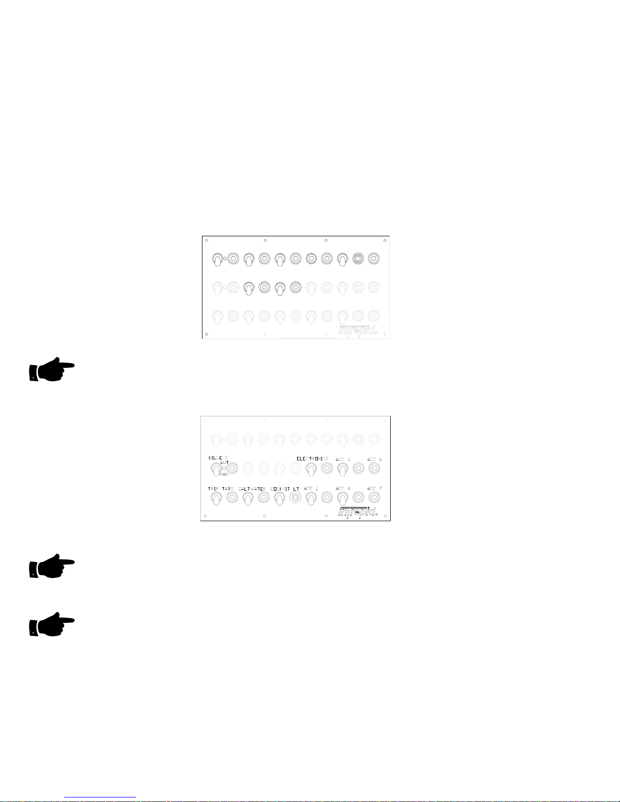
BILGE 1
MACERATOR
AUT
MAN
FRESHW ATER
ACCESSORIES POWERED BY PORT BATTERY SYSTEM AND BATTERY SWITCH
NOTE
The Bilge Pump circuit on the upper side of the Switch Panel is powered by the Port Battery
System but is not controlled by the Port Battery Disconnect Switch. This Bilge Pump Automatic
and Manual circuits will remain active even if the Battery Switch is turned OFF.
BAITWELL
CABIN LT
ACC 5ACC 2NAV
ANCHOR
ACCESSORIES POWERED BY STARBOARD BATTERY SYSTEM AND BATTERY SWITCH
NOTE
The Bilge Pump circuit on the lower side of the Switch Panel is powered by the Stbd Battery
System but is not controlled by the Stbd Battery Disconnect Switch. This Bilge Pump’s Automatic
and Manual circuits will remain active even if the Battery Switch is turned OFF.
NOTE
The Switch Panel is constructed such that all the switch handles are pointing down in the OFF
position with the exception of NAV/ANCHOR switch that is OFF in the center position (as shown).
Next to each switch is a waterproof circuit breaker for that switch’s circuit. The circuit breaker is
supplied to protect the boat’s wiring and components. If an electrical problem dev elops in a
circuit, that circuit’s breaker will disconnect the circuit from its power source. Once the problem
has been corrected push the center of the breaker IN to reset the circuit.
D-1

1. NAVIGATION LIGHTS
Your Intrepid has been fitted with Navigation Lighting that is suitable for International Rules and
complies with federal regulations in effect at the time of manufacture.
Navigation Lights should be used between the times of ½ hour before dusk and ½ hour after
dusk, or at times of low visibility.
The Navigation Light circuit is composed of the following lights:
1. One GREEN 10-point side light with a 2-mile visibility located on the starboard side of
the cabin.
2. One RED 10-point side light with a 2-mile visibility located on the port side of the
cabin.
3. One White 360° Masthead/Anchor light with a 2-mile visibility located at least 1 meter
above the side lights.
MASTHEAD / ANCHOR LIGHT
360° WHITE ALL_AROUND
10 POINT SIDE LIGHTS
GREEN - STARBOARD
RED - PORT
When underway during the times required both Side Lights (Port and Starboard) and the
Masthead/Anchor Light should be illuminated.
When anchored during the times required only the Masthead/Anchor Light should be illuminated.
NAV LIGHTS
This portion of the Navigation Light circuit is powered by the Port Battery System and is protected
by a 10-amp circuit breaker. Placing the switch handle to the NAV position will do the following:
1. Turn ON both the Port and Starboard Side Lights
2. Turn ON the Masthead/Anchor Light
3. Turn ON the backlighting for the Switch Panel
4. Turn ON the lights for the Engine Instrumentation
5. Turn ON the lights for the compass (if installed)
ANCHOR LIGHT
This portion of the Navigation’ Light circuit is powered by the Port Battery System and is
protected by the same 10-amp circuit breaker as the NAV light circuit. Placing the switch handle
to the ANCHOR position will turn ON the Masthead/Anchor Light only.
A spare positive wire and a ground wire are marked as STERN SPARE and coiled at the
transom. This red positive wire is controlled by the ANCHOR position of the NAV/ANCHOR
Switch.
D-2
2. TRIM TABS
The Trim Tabs are powered by the Starboard Battery System and its circuitry is protected by a
20-amp circuit breaker.
By placing the Trim Tab switch handle to the ON position (up) power is provided to the Trim Tab
Switches located on the Helm.
Refer to the Trim Tab section in the Control Helm chapter of this Owner’s Manual for instructions
on the use and maintenance of the Trim Tab System.
3. BAITWELL PUMP
STANDARD WITHOUT GENERATOR
The Baitwell Pump is powered by the Port Battery System and a 20-amp fuse protects its
circuitry.
By placing the Baitwell Pump switch handle to the ON position (up) power is provided to the
Baitwell Pump.
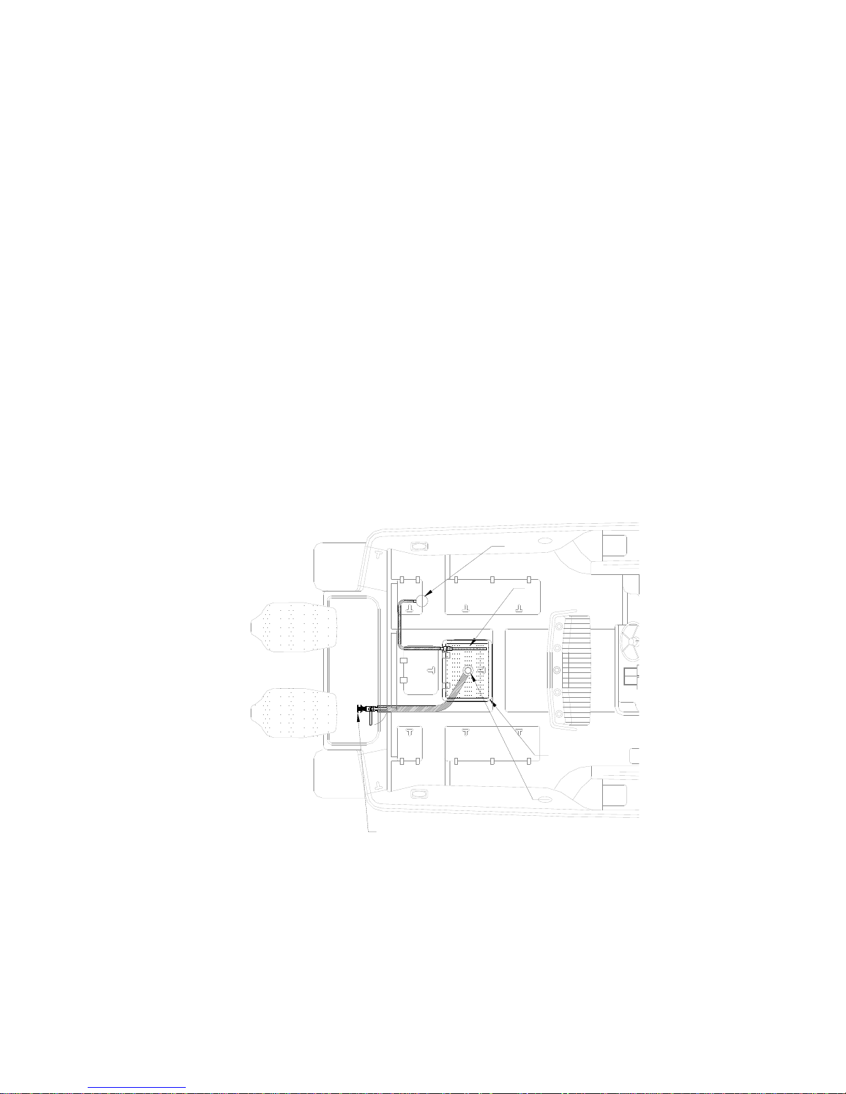
The Baitwell Pump, thru-hull, and seacock are located in the bilge under the Aft Center Bilge
Access Hatch. The Baitwell drain thru-hull and seacock are located further aft in the same
compartment.
BAITWELL PUMP, SEACOCK,
AND THRU-HULL
BAITWELL AERATOR
BAITWELL
BAITWELL DRAIN
BAITWELL DRAIN
SEACOCK AND THRU-HULL
BAITWELL SYSTEM DIAGRAM
The Baitwell Pump draws raw water through the thru-hull and seacock. Water will not be supplied
to the pump if the seacock is closed.
D-3
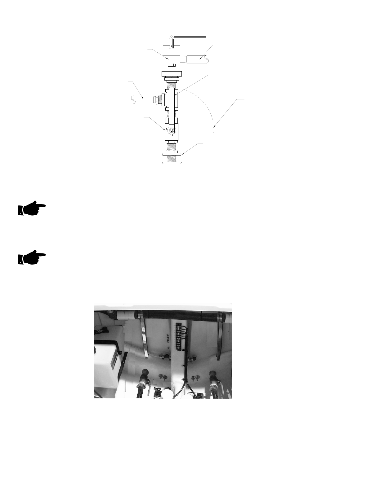
BAITWELL
PUMP
HOSE TO
BAITWELL
HOSE TO SALT
WATER PUMP
SEACOCK
3/4" NPT
HANDLE IN
OPEN POSITION
HANDLE IN
CLOSED POSITION
THRU HULL
3/4" NPT
The level of water in the Baitwell is maintained by the height of the drain tube, which fits within the
drain fitting.
NOTE
The Baitwell will fill beyond capacity if the Baitwell Pump is ON and The Baitwell Drain Seacock
Valve is OFF.
To drain the Baitwell the drain tube must be removed from the drain fitting in the Baitwell and the
Baitwell Drain Seacock Valve must be opened.
NOTE
The Baitwell will not drain completely when not underway. The Baitwell Drain and the Drain Thruhull are both below the waterline of the boat. The Baitwell will only drain to the level of the
waterline of the boat. To completely drain the Baitwell the Drain Seacock must be opened while
the boat is underway (on plane) or when the boat is out of the water. After draining the Baitwell
close the Baitwell Drain Seacock while underway.
BA K ITWELL DRAIN THRU-HULL & SEACOC
D-4
(VALVES SHOWN IN OPEN POSITION)
 Loading...