

Page 1

Instructions for connecting the keypad alone to the
-
1 2 3 4 5 6 7 8 9 10 11 12
1 2 3 4 5 6 7 8 9 10 11 12
+ - D+ D-
-
+
D-
D+
1 2 3 4 5 6 C T
central unit
Residential
Example of cabling a keypad to connector 1
Connector 1
11 to 19 and CRT
Connector 2
21 to 29 and CRT
11 13 14 15 16 17 18 19
+
12
C R T
21 23 24 25 26 27 28 29
22
C R T
Power supply
Max 100 m using 0.6mm diameter wire
Max 200m using 0.9mm diameter wire
Length - Diameter
Keypad card
External clock:
An external clock can be added that
is not managed by the keypad card.
It is the clock that controls
whether or not the door is open.
Note: An extension board can be added to increase the number of doors controlled to 4.
Connector
keypad
Cable attached to the screw
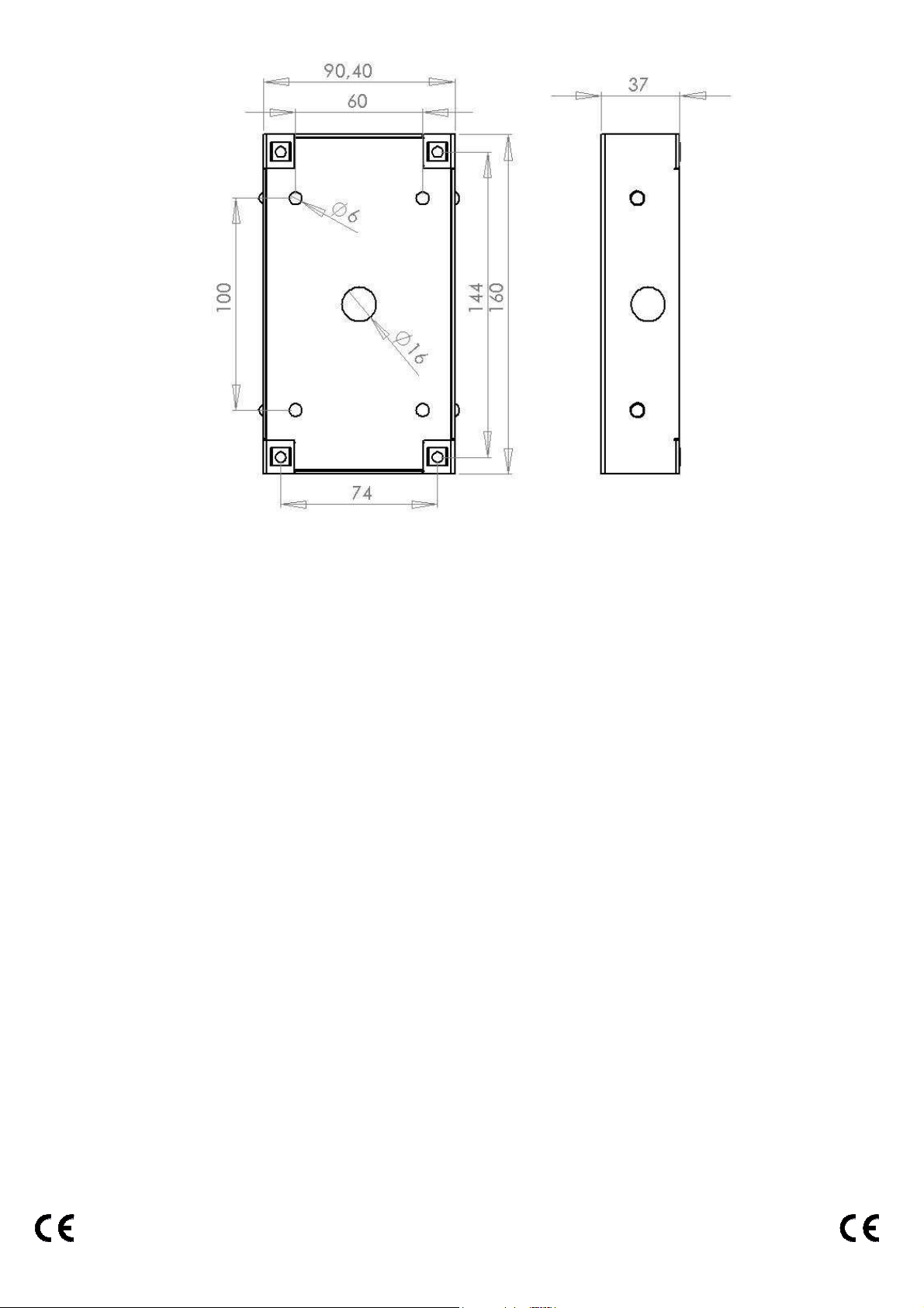
Recessed box
Central unit
terminal blocks
External clock
(not managed)
Instructions for connecting the keypad to the Intratone Residential central unit
Page 1 / 2 V231 – 0054 – AB
Page 2
Instructions for connecting the keypad to the Intratone Residential central unit
Page 2 / 2 V231 – 0054 – AB
 Loading...