

Page 1
07-0106-EN REAL TIME RECEIVER AND
RW
INSTALLATION AND USE
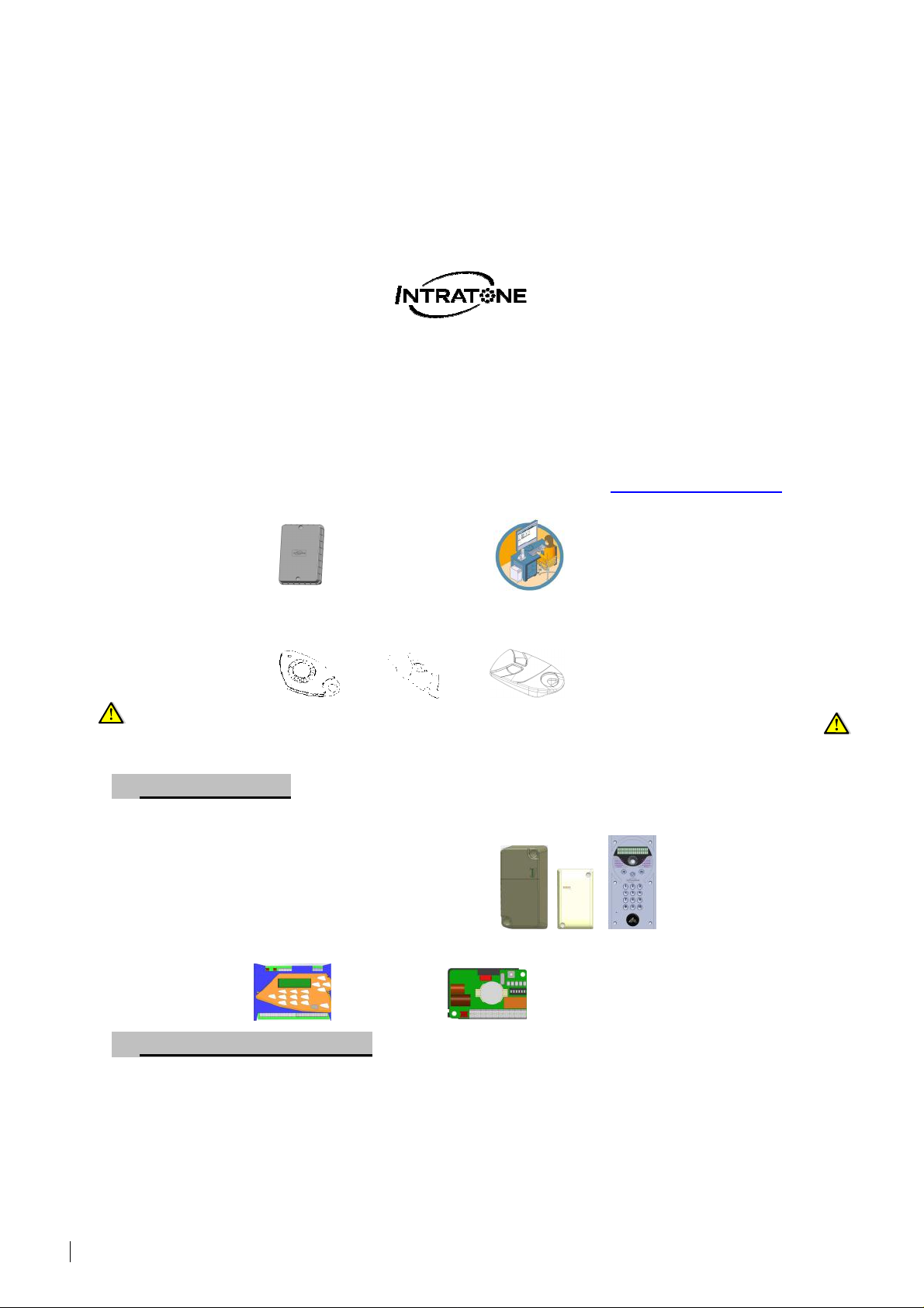
GENERAL POINTS
The Intratone 07-0106-EN (EEN-REC4) receiver has two modes:
- Real time: connected to a control unit and/or GPRS/3G module.
- RW, Read/Write mode (USB programmer required).
- Dip Switch is also available in parallel to these two modes.
It can be managed from the Intratone management website: www.intratone.com in the
“management website” tab.
Running from a 12/24V (AC/DC) power supply, this receiver runs 2 relays (2 NO
contacts) and works with the Intratone range’s 868Mhz remote controls.
Anti-Passback is not available with this model (see. EEN-REC2 or EEN-REC2RW)
A) REAL TIME MODE
In real time mode, this receiver MUST be registered on the Intratone website using one
of the solutions listed below:
- GPRS module
- 3G module
- Visio 2 panel.
Depending upon your needs, you may add an Intratone 03-0101-EN or 03-0102-EN control
unit.
B) RW MODE (READ/WRITE)
This receiver, in Read/Write mode, must be registered on the Intratone website with
the serial number 7xxxxxx5 displayed on the device.
Only the remote controls programmed for the residence will open the doors. When
using a “Key Pass”, the “Pass option” must be activated either with a special remote control
or a “memory charger”.
To program the remote controls, you must use a USB programmer (12-0115-EN / EENPRO-USBHF)
EN-V233 – 5009 – AB – 07-0106-EN (EEN-REC4)
Real Time Receiver and RW Installation and use Page 1 / 11
Page 2

TABLE OF CONTENTS
GENERAL POINTS ----------------------------------------- 1
A) REAL TIME MODE ---------------------------------------------------------------------- 1
B) RW MODE (READ/WRITE) ----------------------------------------------------------- 1
TABLE OF CONTENTS ----------------------------------- 2
DIMENSIONS AND FITTING ----------------------------- 3
WIRING -------------------------------------------------------- 3
EQUIPMENT CONFIGURATION ------------------------ 4
A) LAUNCHING REAL TIME MODE ------------------------------------------------------ 5
B) LAUNCHING RW (READ/WRITE) MODE -------------------------------------------- 5
LED FEATURE ----------------------------------------------- 6
A) LED IN REAL TIME MODE ------------------------------------------------------------ 6
B) LED IN RW (READ/WRITE) MODE -------------------------------------------------- 6
SWITCHES ---------------------------------------------------- 7
A) SWITCHES IN REAL TIME ------------------------------------------------------------- 7
B) SWITCHES IN RW MODE -------------------------------------------------------------- 7
C) SWITCHES 5 AND 6-------------------------------------------------------------------- 7
DIP SWITCHES FEATURE ------------------------------- 8
A) CONCEPT ------------------------------------------------------------------------------- 8
B) HOW DOES IT WORK? ----------------------------------------------------------------- 8
C) SAVING DIP SWITCH CODES ---------------------------------------------------------- 8
D) OPENING WITH DIP SWITCH CODES -------------------------------------------------- 8
E) RESET DIP SWITCH CODES (RAZ) -------------------------------------------------- 8
INSTALLATION PRECAUTIONS ----------------------- 9
ROLLING CODE OPERATION -------------------------- 9
STANDARDS: ---------------------------------------------- 10
A) EC STANDARDS --------------------------------------------------------------------- 10
B) CABLING ------------------------------------------------------------------------------ 10
C) END OF LIFE PRODUCT RECYCLING ----------------------------------------------- 10
CERTIFICATE OF CONFORMITY -------------------- 11
EN-V233 – 5009 – AB – 07-0106-EN (EEN-REC4)
Real Time Receiver and RW Installation and use Page 2 / 11
Page 3
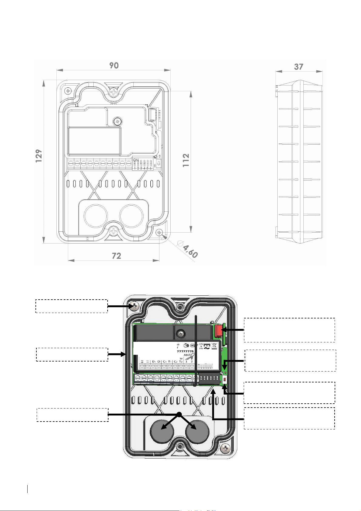
DIMENSIONS AND FITTING
r
Wall bracket
Waterproof seal
Cable Tie
Waterproof HF eco receive
Real time or RW modes
Ref: HREC4 canon number :
POWER BUS Input Output
RW memory
(removable)
-buttons
-2/3-4
LED Detection
of Dip Switches
Dip Switch detector
button
Switches
for settings
EN-V233 – 5009 – AB – 07-0106-EN (EEN-REC4)
Real Time Receiver and RW Installation and use Page 3 / 11
Page 4

Power supply
100 mA
2 1
AER.
factory)
Dry contact to
To D+/D
-
Real time cabling
OR
12-24V
AC/DC
0.8 – Max 200m
WIRING
Managed devices
2 Relays -1A with 24V
-5A with 12V
With 868Mhz aerial
NOT SUPPLIED
(Optional assembly)
Braid
With wire
(Assembled in
Core
EN-V233 – 5009 – AB – 07-0106-EN (EEN-REC4)
Real Time Receiver and RW Installation and use Page 4 / 11
of GPRS/3G module
and / or
of control unit
03-0101-EN (EEN-CEN12)
03-0102-EN (EEN-CIC12)
REAL TIME
Page 5

EQUIPMENT CONFIGURATION
A) LAUNCHING REAL TIME MODE
To launch the 07-0106-EN (EEN-REC4) receiver in Real Time mode, you must program
the remote controls online and update the device.
B) LAUNCHING RW (READ/WRITE) MODE
To launch the 07-0106-EN (EEN-REC4) receiver in RW (Read/Write) mode, you must
program the remote controls online:
Have the device’s serial number at hand.
Log on to the website with your username and password or create an account
(“create an account” button if logging on for the first time).
Create a residence and then a “07-0106-EN” (EEN-REC4) access by entering the
serial number for receiver 07-0106-EN (EEN-REC4).
You will then be able to program the remote controls that you will allocate to
residents.
The remote controls will automatically open the doors controlled by the receiver. The
first control will launch the receiver.
If you need to make “Key Pass” controls, then you must activate the pass option by
programming a special remote control on the website (“Activate Pass Option” button from
the “control unit” menu on the receiver’s screen).
Press a button on the “Pass Option” remote control in front of the receiver. The passes will
then open.
EN-V233 – 5009 – AB – 07-0106-EN (EEN-REC4)
Real Time Receiver and RW Installation and use Page 5 / 11
Page 6

LED FEATURE
M
Normal operation
in real time mode:
Permanently OFF
New device in RW (Read/Write) mode:
Device operating in RW mode:
Pass option activated in RW mode:
Solid Light
Flashes
Real Time
RW
: Check cabling Device not detected ☺: Cabling OK Device detected
STATE
A) LED IN REAL TIME MODE
Flashing for 1 to 2 sec
Permanently ON
Goes off for 1 second
Twinkling
B) LED IN RW (READ/WRITE) MODE
Power supply on
After switch of switch 6: delete rolling code.
☺☺☺☺
Diagnostic displays “HF” on 03-0101-EN control unit
HF transmission from 868Mhz Intratone remote
control received properly.
Error on data bus: Check D+/D- terminals
No power to receiver: Check +/- terminals
EANING
Flashing for 1 to 2 sec
1 flash every 3 sec
2 flashes every 3 seconds
Constant slow flashing
Lighted for 1 second
2-3 seconds quick flashes
10 seconds quick flashes
Twinkling
Permanently OFF
Power supply on
After switch of switch 6: delete rolling code.
A programmed remote control has not yet been
used with the receiver.
If switch 6 is set to ON (see page 7), all Intratone
remote controls, programmed or not, are authorized.
☺☺☺☺
The receiver will work with remote controls
programmed for residents on the website with a
USB programmer.
Access control is active: only authorized residents
may enter with their remote controls.
“Pass Keys” do not work in this mode.
(see section on device configuration).
Receiving an HF transmission from a remote control.
Detecting a new remote control
Receiver launching
Memory invalid or missing
No power to receiver: Check +/- terminals
EN-V233 – 5009 – AB – 07-0106-EN (EEN-REC4)
Real Time Receiver and RW Installation and use Page 6 / 11
Page 7

SWITCHES
Timing of relay openings
S 1 S 2 S 3 Opening
Switch
0.2 sec
SECURING ACC
ESS
:
01 sec
03 sec
05 sec*
10 sec
15 sec
30 sec
60 sec
Timing of relay
Which button should be used on the remote
S 1 S 2 S 3 Opening
S 4 Using buttons
0.2 sec
- I and II on 4 button
01 sec
03 sec
03 sec
10 sec
- III and IIII on 4 button
15 sec
30 sec
60 sec
Switch 5
: Function that “authorizes the use of saved Dip Switches”
S5
S5
Switch no.6: RAZ and Secure Features
Always position switch 6 to OFF
A) SWITCHES IN REAL TIME
“INPUT” and “OUTPUT”
OFF OFF OFF
ON OFF OFF
OFF ON OFF
ON ON OFF
OFF OFF ON
ON OFF ON
OFF ON ON
ON ON ON
*05 sec or timing defined by control unit.
B) SWITCHES IN RW MODE
openings
“INPUT” and “OUTPUT”
S6
S4
control?
Other switches
Details
Always set to OFF.
Note: Restarting has no effect on Real Time
mode.
Not used in this mode!
OFF OFF OFF
ON OFF OFF
OFF ON OFF
ON ON OFF
OFF OFF ON
ON OFF ON
OFF ON ON
ON ON ON
C) SWITCHES 5 AND 6
ON Activates Dip Switch opening.
1)SECURING ACCESS: Always position switch 6 to OFF
2) Resetting the 07-0106-EN (EEN-REC 4) receiver in “read/write” mode:
Following a reset, all Intratone RW remote controls will be deleted from the memory.
Remember to set S6 to OFF The receiver is reset to its factory settings.
To reset the receiver:
Click switch 6 (the LED lights up) and wait until the LED begins to flash.
Repeat this action twice until the LED flashes quickly.
As soon as the LED flashes once every 3 seconds, the reset is complete and the 07-
Turn the switch back to OFF.
OFF Prevents Dip Switch opening.
0106-EN (EEN-REC4) receiver has been returned to factory settings and RW mode.
OFF
ON
remote controls.
- Left and Right for
2 button remote controls
remote controls.
- 2 button remote controls
do not work in this mode
EN-V233 – 5009 – AB – 07-0106-EN (EEN-REC4)
Real Time Receiver and RW Installation and use Page 7 / 11
Page 8

DIP SWITCHES FEATURE
A) CONCEPT
The Dip Switch function enables RW and Real Time modes to be opened independently.
The receiver saves a Dip Switch code using the detection push-button. The remote control
with the same Dip Switch code will now open the door.
Switch 5 in the ON position activates this feature.
The receiver can save up to 10 different Dip Switch codes.
B) HOW DOES IT WORK?
The receiver recognises one of the Dip Switch codes on an Intratone remote control, and
authorizes the entrance or exit to open.
Only Intratone remote controls made later than 2014
software/hardware installed can use this mode.
C) SAVING DIP SWITCH CODES
1) Press once on the “Dip Switch” detector button.
2) The LED above the button remains lighted. You have 10 seconds to press one of the
buttons on a pre-programmed remote control with “Dip Switch”.
3) The remote has been saved when the LED begins to flash.
4) To exit detection mode: Press once on the push-button or wait for the LED to switch off.
and with the Intratone Dip Switch
D) OPENING WITH DIP SWITCH CODES
From then on, each remote control with a “Dip Switch” code saved by the receiver will be
authorized to open doors.
Note:
This is true independent of RW or Real Time modes.
E) RESET DIP SWITCH CODES (RAZ)
1) Press and hold the “Dip Switch” detector button for 3 seconds.
2)The LED above the button flashes quickly:
10 second waiting time to confirm RAZ.
2) Press PB once (before end of 10s wait)
RAZ confirmed and return to normal mode.
3) Following this, all “Dip Switch” codes are deleted. No remote control will operate in
this mode.
It is impossible to cancel a specific remote or “Dip
switch” code in “Dip Switch” mode: it’s all or
nothing!
EN-V233 – 5009 – AB – 07-0106-EN (EEN-REC4)
Real Time Receiver and RW Installation and use Page 8 / 11
Page 9

INSTALLATION PRECAUTIONS
The receiver must not be enclosed in a metal case or placed behind a protective area
that uses metallic wire netting. In the event that you cannot do otherwise, you must
connect the 868 MHz aerial that you will fit outside.
To achieve satisfactory operation, there must be no metal obstacles between the active
aerial and the normal position used for operating the remote controls. It is therefore
preferable to fit the receiver in a high location to avoid obstacles (e.g. metallic wire
netting).
Drill the holes as accurately as possible in the cable pass throughs to prevent any
water seeping into the receiver. Failure to comply with this requirement will void the
warranty.
Never connect the relays' C1/T1 or C2/T2 terminals directly to a power
supply.
a pushbutton-type input to the devices that need controlling. If these devices do not
have an input of this kind, use an intermediate power relay of the correct capacity.
Notes:
If the range of the remote controls is too low (the 07-0106-EN receiver fails to detect a
signal): position the aerial (NOT-PROVIDED) in different locations to find the best one (if
possible in an open space away from metal structures so as to prevent interference).
These relays supply a voltage-free contact relay designed to be connected to
ROLLING CODE OPERATION
The receiver manages the rolling codes emitted by the remote controls. They are intended
to counter attempts at making fraudulent copies of remote controls (through reproducing
the signal emitted by the remote control).
This means that a different code is transmitted each time a button is pressed, a code that
must match the unique criteria of the 07-0106-EN receiver. The security of your site is thus
optimal.
It may become necessary to delete the rolling codes saved on the receiver (If the
receiver is moved to another site, for example). This is carried out when the receiver is
turned on, or when switch 6 is set to the ON position (Put switch 6 back to OFF
position).
EN-V233 – 5009 – AB – 07-0106-EN (EEN-REC4)
Real Time Receiver and RW Installation and use Page 9 / 11
Page 10

STANDARDS:
A) EC STANDARDS
The HF 868Mhz 07-0106-EN (EEN-REC4) receiver complies with the directive R&TTE
1999/5/EC: electrical safety standard EN 60950 (2000) applied, EMC standard EN 301
489-3 (2000) applied, radio standard EN 300 220-3 (2000) applied.
B) CABLING
Please be sure to follow the recommendations given on the cabling and connection
diagrams, especially concerning the distance and diameter of wiring between the HF
receiver and the control unit of GSM/3G unit. If this is not the case, no warranty will be
given.
C) END OF LIFE PRODUCT RECYCLING
The receiver and its accessories must not be disposed of with unsorted waste, but
must be collected for recycling as Electrical and Electronic Waste.
EN-V233 – 5009 – AB – 07-0106-EN (EEN-REC4)
Real Time Receiver and RW Installation and use Page 10 /
11
 Loading...