

Page 1
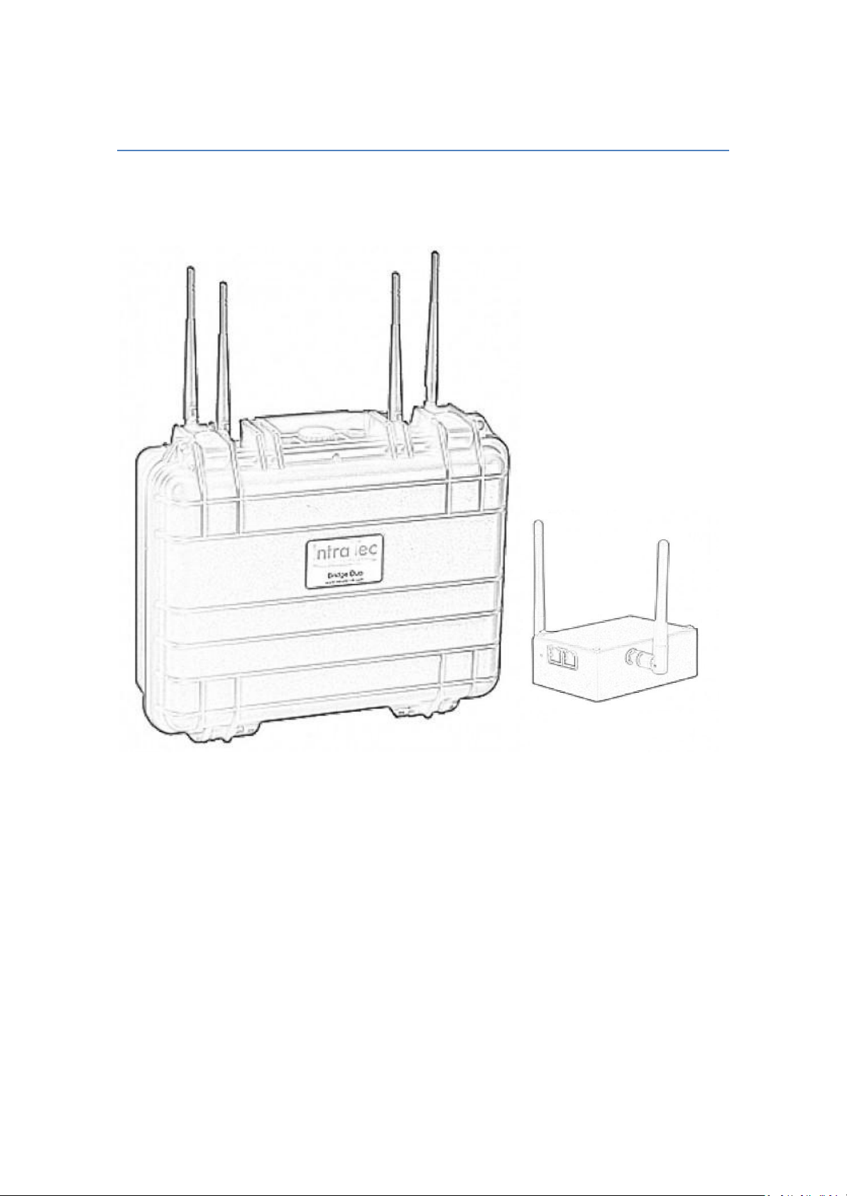
Bridge 2 & Bridge Duo 2
Long Range Wireless Dist ribution
Page 2

IntraTec Solutions Ltd
www.intratec-uk.com
2
Page 3

Contents
Packing List ..................................................................................................................................... 4
Bridge 2 ....................................................................................................................................... 4
Bridge Duo 2 ............................................................................................................................... 4
Operation Modes ............................................................................................................................ 6
Access Point WDS Mode ............................................................................................................. 7
Station WDS Mode ..................................................................................................................... 7
Repeater WDS Mode .................................................................................................................. 8
Station Mode .............................................................................................................................. 9
Access Point Mode ..................................................................................................................... 9
Router Mode............................................................................................................................... 9
Quick Setup ................................................................................................................................... 10
Hardware Configuration & Considerations .................................................................................. 12
Antenna Selection..................................................................................................................... 12
Antennas and WiFi Power Limits .............................................................................................. 13
Antenna Ports ........................................................................................................................... 14
Power Input .............................................................................................................................. 14
Power Output ........................................................................................................................... 14
Antenna Alignment ................................................................................................................... 15
Advanced Configuration ............................................................................................................... 17
Web Interface Navigation ......................................................................................................... 18
Basic Wireless ........................................................................................................................... 19
Advance Wireless ..................................................................................................................... 32
Basic Network ........................................................................................................................... 35
Advanced Network ................................................................................................................... 39
Services Tab .............................................................................................................................. 45
System Tab ................................................................................................................................ 49
VLAN Tab .................................................................................................................................. 52
IntraTec Solutions Ltd
www.intratec-uk.com
3
Page 4

Packing List
Description
QTY
Bridge 2
1
Ethernet cable
1
¼ hot shoe mount
1
International mains PSU
1
Instruction manual
1
3 dBi antenna
2
Description
QTY
Bridge Duo 2
1
Ethernet cable
1
Instruction Manual
1
5 dBi antenna
4
Bridge 2
Bridge Duo 2
IntraTec Solutions Ltd
www.intratec-uk.com
4
Page 5

FCC NOTICE
This device has been tested and found to comply with the limits for a Class B digital device,
pursuant to Part 15 of the FCC Rules. These limits are designed to provide reasonable
protection against harmful interference in a residential installation. This device generates
uses and can radiate radio frequency energy and, if not installed and used in accordance with
the instructions, may cause harmful interference to radio communications. However, there is
no guarantee that interference will not occur in a particular installation. If this device does
cause harmful interference to radio or television reception, the user is encouraged to try to
correct the interference by one or more of the following measures:
•
Reorient or relocate the receiving antenna.
•
Connect the computer to an outlet on a circuit different from that to which the
receiver is connected.
•
Increase the separation between the computer and receiver.
•
Consult the dealer or an experienced RF technician for help.
Caution: Any changes or modifications not expressly approved by the grantee of this
device could void the user's authority to operate the equipment.
FCC Compliance Statement: This device complies with Part 15 of the FCC Rules. Operation
is subject to the following two conditions:
This device may not cause harmful interference, and
This device must accept any interference received, including interference that may
cause undesired operation.
RF Exposure warning
The equipment complies with FCC RF exposure limits set forth for an uncontrolled
environment. The equipment must not be co-located or operating in conjunction with any
other antenna or transmitter.
ICES 003 Statement
This Class B digital apparatus complies with Canadian ICES-003.
IntraTec Solutions Ltd
www.intratec-uk.com
5
Page 6

Operation Modes
Bridge operating mode is selected by default. In this mode the device will act as a transparent
bridge and will operate at Layer 2. There will be no network segmentation and the broadcast domain
will be the same. Bridge mode will not block any broadcast or multicast traffic. Additional Firewall
settings can be configured for Layer 2 packet filtering and access control. In bridge mode the device
forwards all the network management and data packets from one network interface to the other
without any intelligent routing. For simple applications this provides an efficient and fully transparent
network solution. WLAN (wireless) and LAN (Ethernet) interfaces belong to the same network segment
which has the same IP address space. The devices IP address is for management purposes only.
Router operating mode can be configured in order to operate at Layer 3 to perform routing and enable
network segmentation, clients will be on a different IP subnet. Router mode will block broadcasts and is
not transparent.
The device supports Multicast packet pass-through when in Router mode. T h e router can use the
Network Address Translation (Masquerading) feature, NAT will act as the firewall between the LAN and
WLAN networks. Additional Firewall settings can be configured for Layer 3 packet filtering and access
control when in Router mode.
IntraTec Solutions Ltd
www.intratec-uk.com
6
Page 7
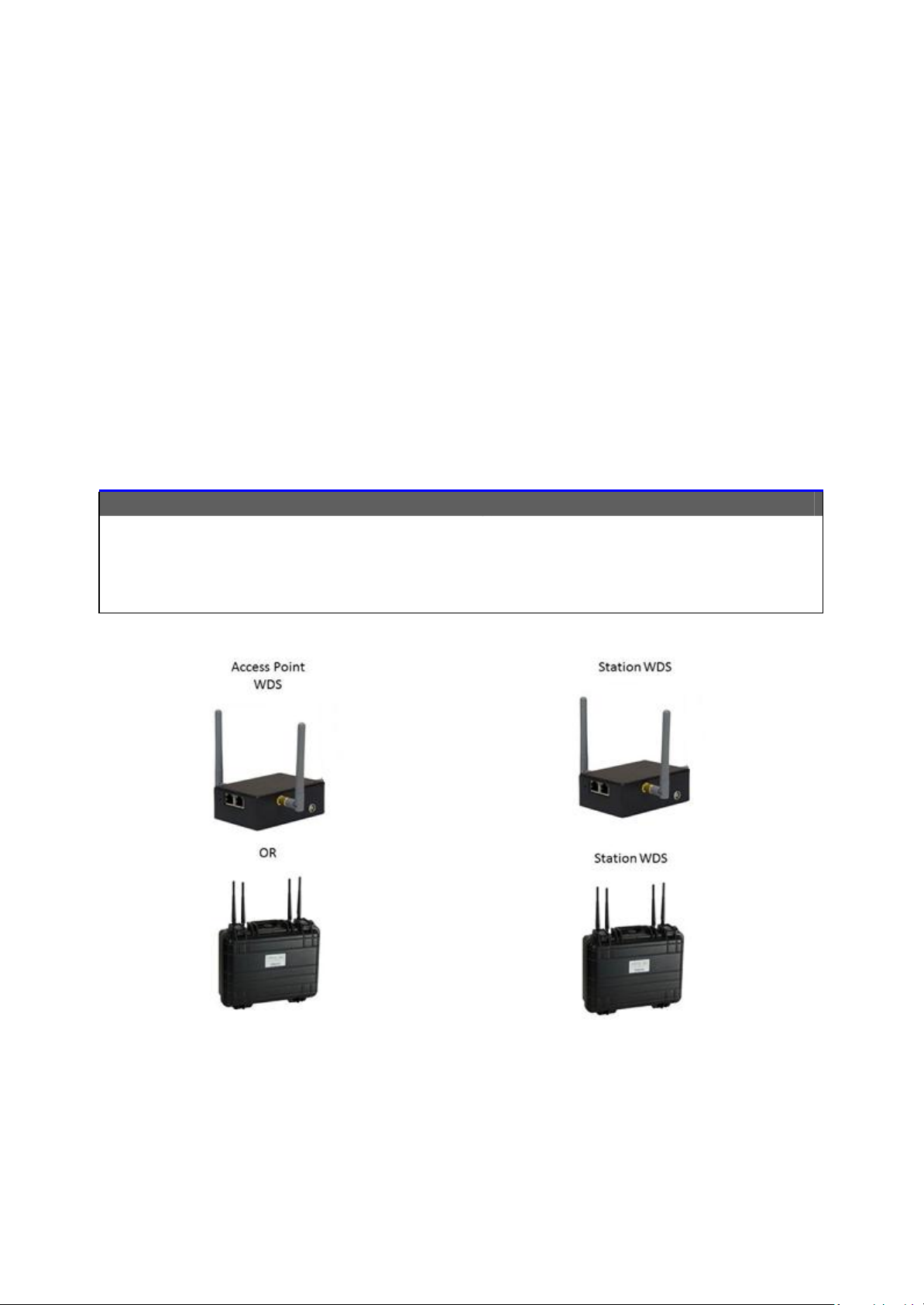
Access Point WDS Mode
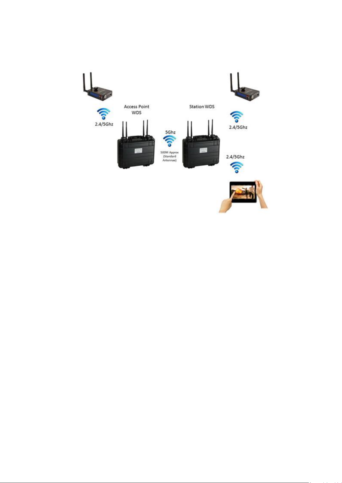
This is mode is generally used for point-to-point or point-to-multi-point connections between bridge
units. A unit in Access Point WDS mode should be used in conjunction other units in Station WDS mode
in order to build the point to point and multi-point connections. This is the most commonly used mode
to connect two units, by using the WDS (Wireless Distribution System) protocol both devices are
connected transparently just like having an Ethernet cable between them.
Station WDS Mode
A device in Station WDS mode must be connected to a no t h e r u n it configured in Access Point WDS
mode. This is the most commonly used mode to connect two units, by using the WDS (Wireless
Distribution System) protocol both devices are connected transparently just like having an Ethernet
cable between them.
Point-to-Point
One unit is setup as Access Point WDS and the
other as Station WDS (Transparent Client).
Point-to-MultiPoint
One unit is setup as Access Point WDS and several
other devices as Station WDS (Transparent
Clients).
IntraTec Solutions Ltd
www.intratec-uk.com
7
Page 8
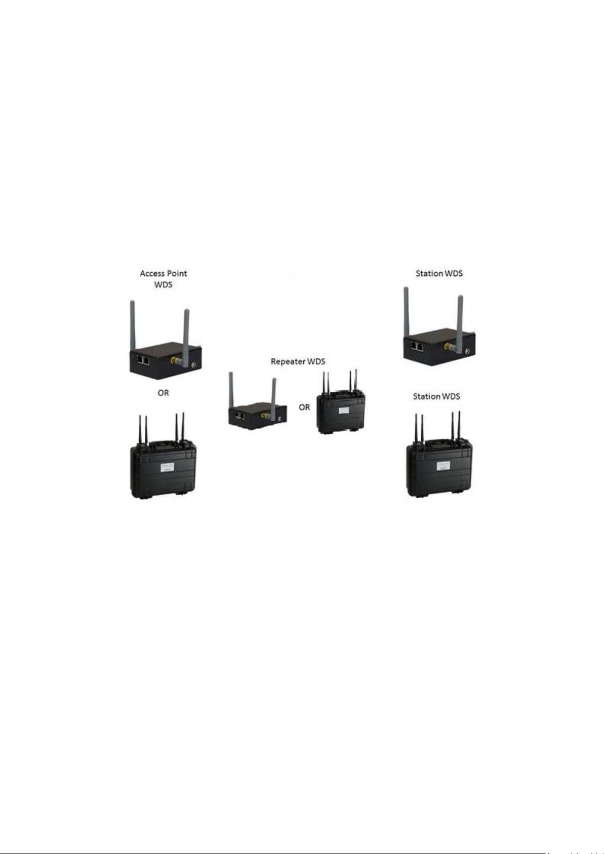
Repeater WDS Mode
Repeater WDS Mode is used to extend the wireless range and coverage of the wireless network
between units.
In Repeater mode, the unit acts as a relay by regenerating the signals it receives and
retransmitting them to main network infrastructure.
Note: Repeater WDS requires another unit setup in Access Point WDS mode in order to work.
IntraTec Solutions Ltd
www.intratec-uk.com
8
Page 9
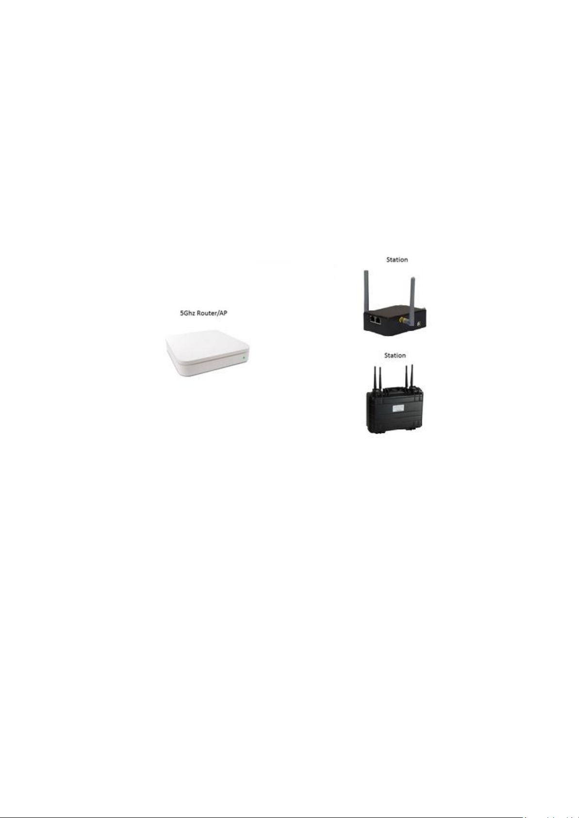
Station Mode
In Station mode the device acts as a wireless client.
Use this mode to connect the bridge unit to any standard access point or wireless router. When connected
to an access point the wired network ports are bridged to the wireless network. This mode translates all
the packets that pass through device to its own MAC address, thus resulting in a lack of transparency.
Note: We cannot guarantee compatibility with all access points/routers.
Access Point Mode
The Access Point Mode is the default mode of the device. In this mode the unit simply bridges the
wireless clients to other wired and wireless network infrastructure.
Router Mode
In Router Mode, the device operates as a router.
Either the wireless or Ethernet can be setup as the WAN connection. Wireless as WAN is known as
Station + Router mode (or Wireless Routing Client mode) or Ethernet as WAN is known as AP +
Router mode (or Gateway mode). This device supports several types of broadband connections Static
IP, Dynamic IP and PPPoE.
IntraTec Solutions Ltd
www.intratec-uk.com
9
Page 10
Quick Setup
By default the Bridge 2 and Bridge Duo 2 units are configured ready to pair with each other, we simply
need to specify which unit will be the access point and which unit(s) will be the station(s)
Configuration Walkthrough
One the first Bridge or Bridge Duo Unit
1. Assign your computer a static IP address in the 192.168.168.X range (192.168.168.254 for
example) and connect to the units Ethernet port.
2. Open a web browser (For example Google Chrome, Internet Explorer) and navigate to
192.168.168.1.
3. Log-in to the web interface with the username admin and password password.
4. Select BASIC WIRELESS then RADIO 1.
5. Set the Wireless Mode to Access point WDS..
6. Optional: Uncheck the No Country Set box and select your country of residence from the drop
down menu. Please Note: Some countries have DFS (Dynamic Frequency Selection)
characteristics enforced by regulations, this may cause a delay of 2 to 10 minutes for both
devices to finish scanning and establish a connection.
7. Click Apply Settings and then save the changes.
8. Optional: If you do not intend to manually assign all connected devices IP addresses you may
want to enable the devices DHCP server, this will automatically issue an IP address to any device
connected to both Bridge units (this only needs to be enabled on the device in Access Point WDS
IntraTec Solutions Ltd
www.intratec-uk.com
10
Page 11

mode. To enable the DHCP server select BASIC NETWORK and set DHCP Mode to DHCP Server.
9. The first unit is now configured as the access point, additional units should be configured as
stations.
10. The next steps are optional and apply to Bridge Duo units only. By default the Bridge Duos
secondary radio is configured as a 2.4Ghz local access point without any security, to change this
configuration:
11. Select BASIC WIRELESS then RADIO 2.
12. Optional: Uncheck the No Country Set box and select your country of residence from the drop
down menu. Please Note: Some countries have DFS (Dynamic Frequency Selection)
characteristics enforced by regulations, this may cause a delay of 2 to 10 minutes for both
devices to finish scanning and establish a connection.
13. Optional: Uncheck the Hide SSID box for RADIO2 to allow the radio to be found automatically.
14. Select either NA (5Ghz 802.11a/n) or NG (2.4Ghz 802.11g/n) for the Wireless Profile field. We
recommend using NG for the local access point for increased device compatibility.
15. Finally you can configure wireless security for the local access point. To enable security select the
WPA2 option from the Security drop down menu and then enter your password of choice into
the WPA Preshared Key field.
16. Click Apply Settings and then save the changes.
One the second Bridge or Bridge Duo Unit
1. Connect your computer to the second units Ethernet port.
2. Open a web browser (For example Google Chrome, Internet Explorer) and navigate to
192.168.168.1.
3. Log-in to the web interface with the username admin and password password.
4. Select BASIC Network and change the IP Address fields value to 192.168.168.2., you should
increment the IP address for each additional unit you connect for example the unit after this
should be assigned 192.168.168.3.
5. Click Apply Settings and then save the changes.
6. The second unit can now be accessed at 192.168.168.2 and the first at 192.168.168.1. This
means that when both units are connected you can access and configure each unit from either
end of the link.
7. Open your web browser again and navigate to 192.168.168.2, Log-In again if required.
8. Select BASIC WIRELESS then RADIO 1.
9. Set the Wireless Mode to Station WDS.
10. Optional: Uncheck the No Country Set box and select your country of residence from the drop
down menu. Please Note: Some countries have DFS (Dynamic Frequency Selection)
characteristics enforced by regulations, this may cause a delay of 2 to 10 minutes for both
devices to finish scanning and establish a connection.
11. Click Apply Settings and then save the changes.
12. Both units are now configured and should pair after a short period.
13. Optional: You can configure the secondary radio as you did for the first unit.
IntraTec Solutions Ltd
www.intratec-uk.com
11
Page 12

Hardware Configuration & Considerations
This section will show you how to install the hardware of the Bridge / Bridge Duo unit and its optional
accessories.
Antenna Selection
It is important to remember that antennas create gain by focusing or directing signals, this means that for
an antenna to provide increased gain it will be focusing the signal in one direction so we must loose
signal in another direction.
A 0dBi Omni-directional antenna creates a perfect spherical response meaning that the signal is spread
equally in all directions (360 degree vertical and horizontal planes). A standard 3dBi Omni-directional
antenna creates a doughnut shaped response, we have gained signal from the side of the antenna at the
cost of losing it above the antenna (narrower vertical plane). This effect is increased when we move to
say an 8dBi Omni-directional antenna, we now have a thin disc shaped response (even narrower vertical
beam width) making it more important that both antennas are on the same level ground or angled
appropriately.
With directional antennas such as a 19dBi panel we narrow both the vertical and horizontal planes to
create a highly directional beam.
As standard the Bridge Duo is fitted with 5dBi Omni directional antennas for the high power backhaul
radio and the secondary radio, the Bridge is fitted with 3dBi antennas. These antennas provide a wide
(almost spherical) signal spread so are ideal for cases when the secondary radio is to be used as a local
access point and the primary radio is used to link two bridge units over moderate distances without
accurate alignment, or in cases where the bridge units will be moving. For longer range deployments we
offer two optional antennas;
19 dBi Dual Polarised Panel Antenna
This directional antenna is ideal for linking two Bridge Duo units (Point to point) over longer distances, its
25 degree horizontal beam width and dual polarisation (horizontal and vertical) greatly simplify
alignment and allow dual stream data rates to be used increasing throughput. When used in conjunction
with the standard 5dBi antennas on the secondary radio of the Bridge Duo (used as an access point) this
combination allows very long range links while still allowing client devices to roam freely within the local
access points range.
8 dBi Omni-Directional Antenna
This Omni-directional antenna is ideal for linking two or more (Point to Multipoint) Bridge / Bridge Duo
units over longer distances. Its 360 degree horizontal beam width allows the unit in Access Point WDS
mode to be located in a central location and have many more units in station WDS mode located around
it. This antenna is also ideal for situations where the units may be moving but will stay on the same
ground level.
IntraTec Solutions Ltd
www.intratec-uk.com
12
Page 13

Antennas and WiFi Power Limits
It is important to ensure that you obey local regulations relating to the permitted transmit power of WiFi
devices. In the later sections of this manual you will see that by selecting your country of residence the
device will automatically ensure it is using only permitted frequencies and a legal transmit power,
however this is only the transmit power at the antenna port you may need to further decrease the
transmit power to stay within regulatory limits depending on the antennas used.
The limits for the UK are:
5Ghz Band B (5470-5725MHz) - License free use up to 1000mw 30dBm (EIRP)
2.4Ghz (2.412GHz ~ 2.472GHz) – License free use up to 100mw 20dBm (EIRP)
The EIRP power (Equivalent isotropically radiated power) is the combined emitted power of the radio and
the gain of the antenna.
For example for 5Ghz if the device has a transmit power of 20dBm basic theory tells us you can use an
antenna no stronger than 10dBi gain (20 +1 0 = 30dBm EIRP). In reverse if you have a 19 dBi panel
antenna the devices transmit power must be restricted to approximately 11 dBm (19 + 11= 30dBm EIRP).
However in reality you are allowed to take the loss from the cables and connectors into account, our
wireless link calculator (Available to download) will help you to make these calculations.
Aggregate Power (MIMO)
The above examples assume only one transmit chain (antenna), when transmitting with multiple chains
we must take the aggregate transmit power into consideration (See data sheet for aggregate power
values). The aggregate transmit power only needs to be considered when using 802.11N data rates that
use multiple streams (MCS8 to MCS15) legacy 802.11a data rates and single stream 802.11n rates (MCS0
to MCS7) will only transmit/receive using one chain at a time.
Please note however that these single stream rates will still take advantage of the devices multiple
antennas by using switched diversity (the device selects one of the antennas to transmit and receive on
depending on signal strength). Switched diversity is particularly useful for scenarios when the bridge
units will be moving at an angle that would severely alter the polarity of a single antenna (multiple
antennas can be angled differently to cover the change between horizontal and vertical polarity). See the
antenna alignment section for further information on polarity.
IntraTec Solutions Ltd
www.intratec-uk.com
13
Page 14

Antenna Ports
The Bridge product features two antenna ports both connected to one high power 5Ghz backhaul radio
(these ports are labeled left and right in the software). The Bridge Duo features four antenna ports, the
inner two ports are connected to the high power backhaul radio and the outer two to the dual band
secondary radio (these ports are labeled left and right in the software).
Power Input
The Bridge Duo can be powered from industry standard v-lock batteries or powered over Ethernet*
(Passive PoE 24V-48V, 802.3af PoE 48V-56V).
The Bridge can be powered from any DC 5- 20V DC Source (2 pin Lemo Pin 1 V-, Pin 2 V+, Pin 1 is closest
to the red spot) or powered over Ethernet* (Passive PoE 9-24V).
Please Note: When the Bridge Duo unit is powered via POE the internal power switch must be in the OFF
position for the unit to function, the power output cannot be used in conjunction with POE.
*PoE Kit Sold Separately
Power Output
When running from battery the Bridge Duo also offers a power output port for powering external
devices. The power output provides a regulated 12V 5A feed. The power output socket uses industry
standard 4 pin XLR connectors (Pin 1 GND, Pin4 V+)
An optional power output cable is available offering XLR to 2 pin Lemo, 3.1 and 2.1mm barrel
connectors.
IntraTec Solutions Ltd
www.intratec-uk.com
14
Page 15

Antenna Alignment
The antenna alignment must be considered to ensure that the signal is strong. Remember that the height
of the antennas above the nearest obstacle is critical and increases with longer distance links (As a
general rule you should get the antennas as high as possible).
To gain a better understanding of the antenna height required for a given distance please use our
Wireless Link Calculator (Available to download).
If using the devices supplied Omni directional antennas alignment is not so critical due to their wide
signal spread however you should make sure that both units antennas are angled the same (to avoid a
polarity mismatch). If an antenna is angled on one bridge unit it should also be angled on the other.
Sometimes angling the antennas slightly will help throughput when using multi stream data rates by
separating the two signal paths. Likewise when using a single stream data rates multiple antennas can be
angled differently to cover the change between horizontal and vertical polarity and help reliability (the
unit will monitor all antennas and send/receive on the one with the best signal). See the ‘Aggregate
Power (MIMO)’ section on the previous page for more information.
IntraTec Solutions Ltd
www.intratec-uk.com
15
Page 16
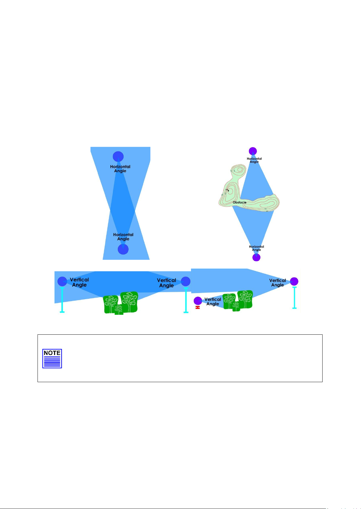
When using our optional directional panel the antenna radiates towards the front of the unit. The unit
should be installed in a position whereby the front of the unit faces the direction you wish to send the
signal to (the receiving antenna). To make alignment easier both units can be connected when at close
range allowing the LED signal indictors to be used when aligning over a larger distance (Only devices in
station or station WDS mode will display signal strength). Our panel antenna is dual polarized, this means
it contains two antennas one is vertical and the other horizontal and allows two data streams to be sent
over great distances without interference between the streams (because of the horizontal and vertical
mismatch)
Info
When the antennas are at the same height, it is quite simple to align the antennas.
However, when the antennas are at different heights, greater care has to be taken.
IntraTec Solutions Ltd
www.intratec-uk.com
16
Page 17
Advanced Configuration
The unit is configurable through any standard web browser. After connecting your computer to the
units Ethernet port using the supplied RJ45 patch lead you need to assign an IP address to your
computer so that it is in the same subnet as the Bridge unit. The units default IP address is
192.168.168.1 so you must assign an address within the 192.168.168.x range (192.168.168.2 to
192.168.168.254).
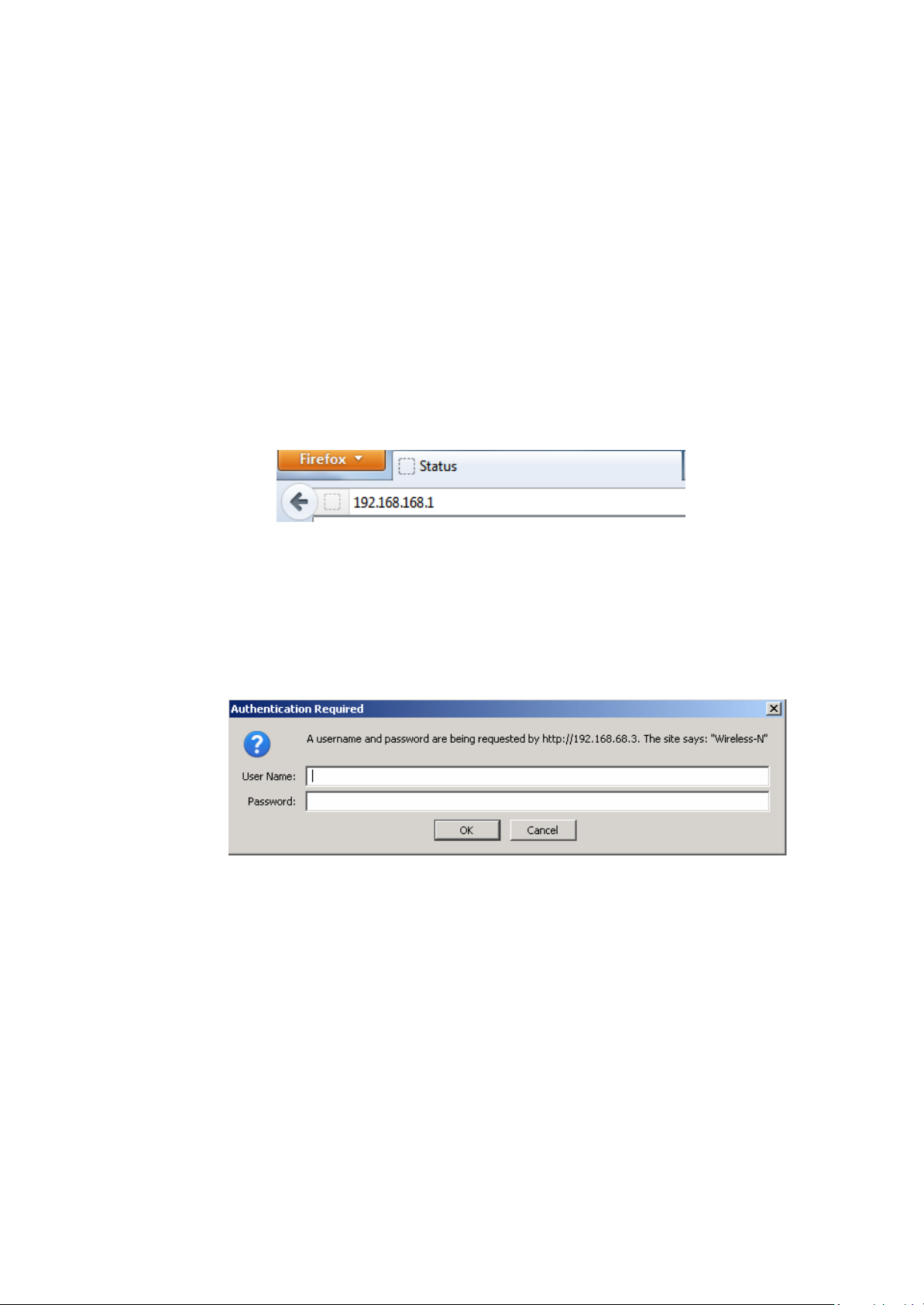
1. Launch your Web browser (Internet Explorer, Firefox, Chrome etc.)
2. At the Address bar type in http://192.168.168.1 and press Enter on your keyboard.
3. At the login prompt, enter the User Name and Password.
User Name: admin
Password: password
IntraTec Solutions Ltd
www.intratec-uk.com
17
Page 18
Web Interface Navigation
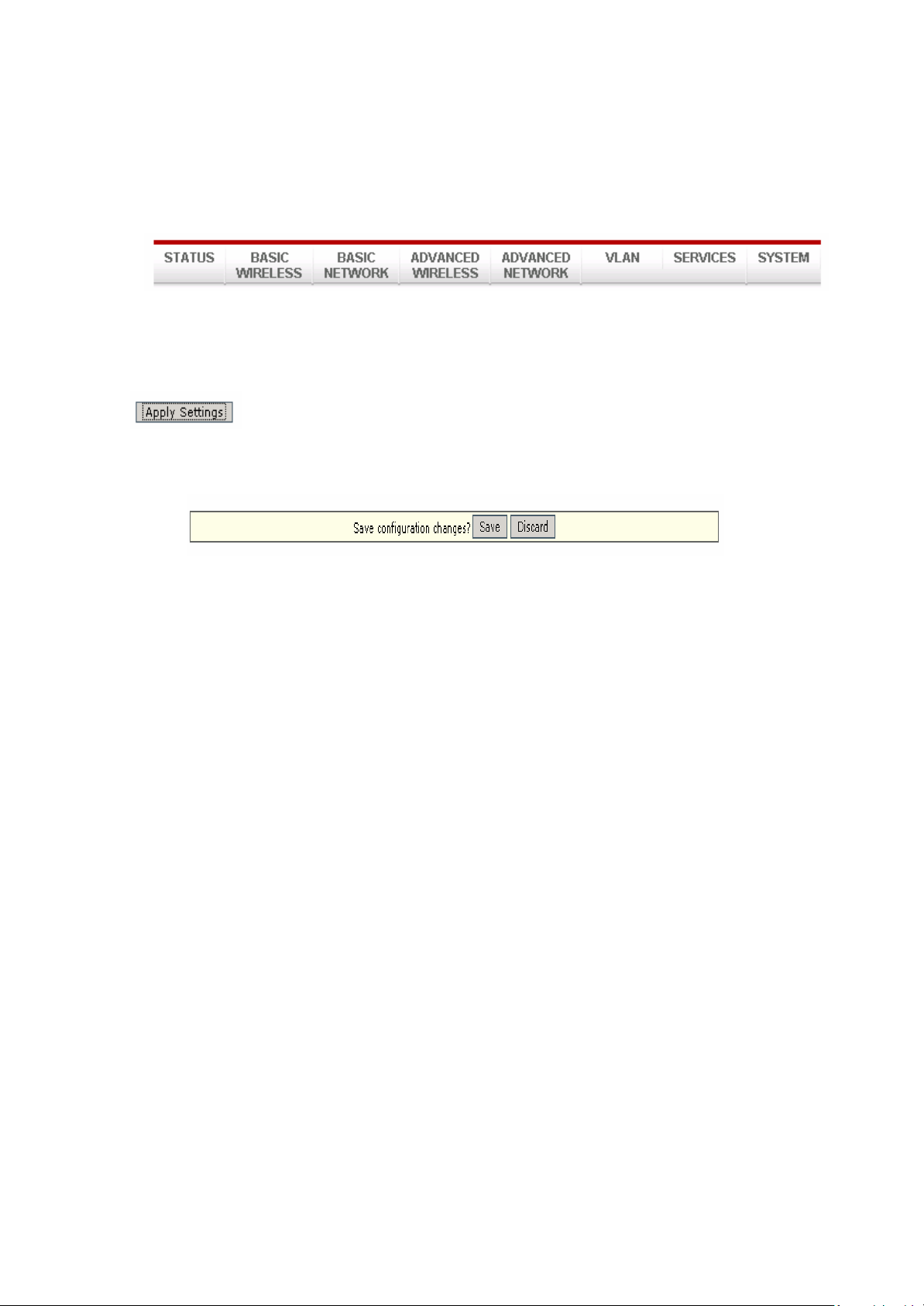
Main Menu Bar
How to save changes
After you make changes from each respective setup page click the Apply Settings button.
Next the prompt below will appear. You are asked to confirm if you want to save the changes
permanently to the devices flash.
Clicking Save will write all configuration changes to flash. Clicking Discard will discard all current
changes.
IntraTec Solutions Ltd
www.intratec-uk.com
18
Page 19

Basic Wireless
Select RADIO 1 to configure the high power backhaul radio or RADIO2 to configure the dual
band secondary radio (Bridge Duo only).
Enable the radio
Check/Uncheck the checkbox to enable/disable the radio.
Basic Wireless Settings
All the basic wireless settings can be configured in this page. Operators can change the ESSID,
regulatory country code, wireless profile, channel spectrum width, frequency, data rates,
transmit power and rate aggressiveness.
IntraTec Solutions Ltd
www.intratec-uk.com
19
Page 20
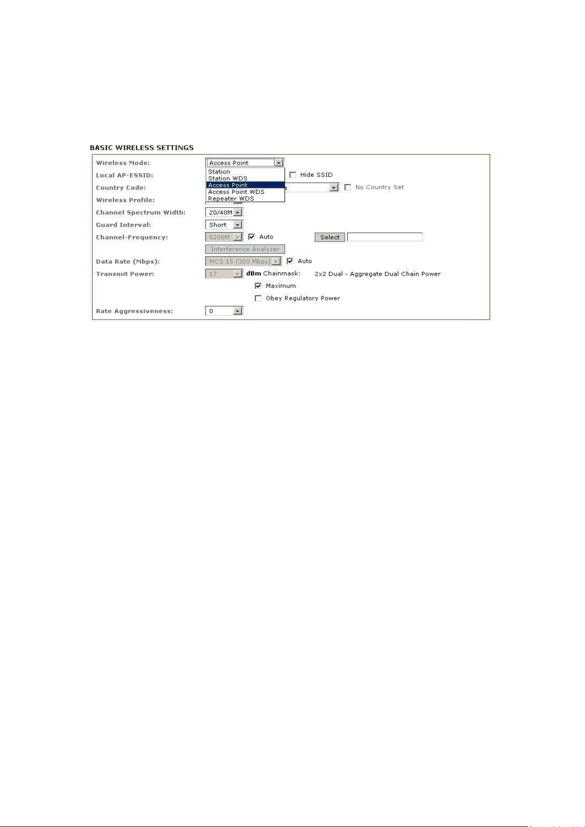
Wireless Mode
There are 5 modes available.
Access Point
The Access Point Mode is the default mode of the device. In this mode the unit simply bridges
the wireless clients to other wired and wireless network infrastructure. Devices in Station mode
can connect to a device in Access Point mode.
Station:
This is a client mode that can be connected to a device in Access Point mode (or any other
wireless access point/router). It is used to bridge the wireless connection to an Access Point, this
mode forwards all the traffic to/from the network devices attached to the Ethernet interfaces.
This mode translates all the packets that pass through to its own MAC address, thus resulting in a
lack of transparency.
Access Point WDS (Recommended)
WDS is the acronym of Wireless Distribution System. This mode can be connected to another
device in Station WDS mode. Using WDS protocol, it allows a client or station device to bridge
wireless traffic transparently. This is the most commonly used mode to connect two bridge
devices.
Station WDS: (Recommended)
WDS is the acronym of Wireless Distribution System. This mode can connect to a device in Access
Point WDS mode. It enables packet forwarding at layer 2 level and unlike Station mode, it is fully
transparent. This is the most commonly used mode to connect two bridge devices.
Note: The WDS protocol used is not defined as a standard, thus compatibility issues between
equipment from different vendors may arise.
IntraTec Solutions Ltd
www.intratec-uk.com
20
Page 21
Repeater WDS
This mode consists of a device in Station WDS mode and a device in Access Point WDS mode. The
Repeater WDS must first link up with a device in Access Point WDS mode, then it can link up with
a device in Station WDS modes. It acts as an extension to the link, more Repeaters can be added
as necessary.
Note : The ESSID must be the same for the Remote AP and the Local AP. The channels used by
the Repeater to link to another Repeater will follow the selected channel on the device in
Access Point WDS mode.
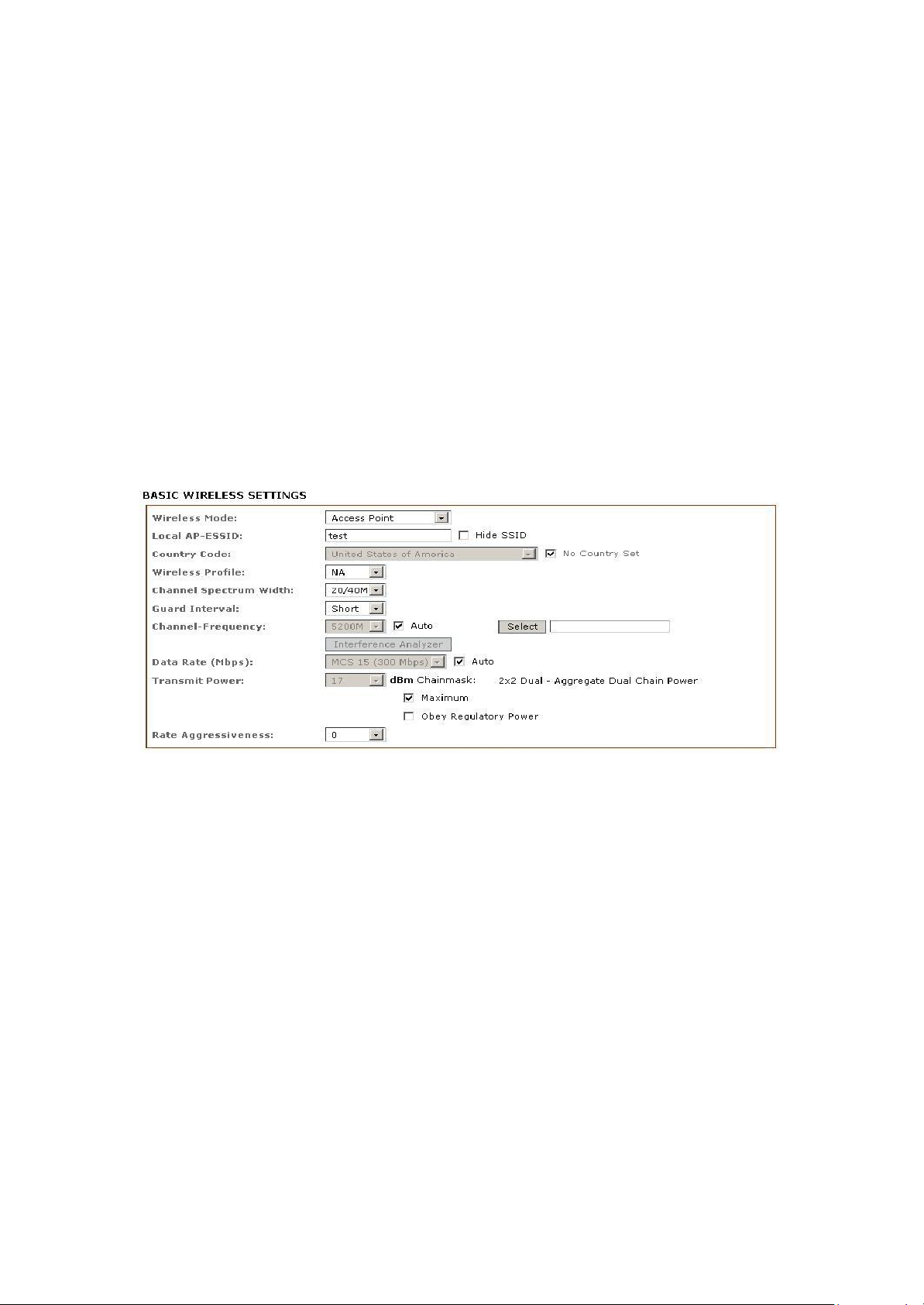
Access Point Parameters Settings
Local AP-ESSID
This is the Service Set Identifier used to identify this units wireless LAN. It should be specified
while operating in Access Point or Access Point WDS mode.
All the client devices within its range will receive broadcast messages from the access point
advertising this SSID.
Hide SSID:
Once checked, this will disable advertising of the SSID of the access point . This option is
only available in Access Point, Access Point WDS and Repeater WDS mode only.
Country Code
Different countries have different power levels and also frequency selections. To ensure
the devices operation follows regulatory compliance rules, the operator should make sure that
correct country code where device will be used is selected. The channel list, output power limits,
IntraTec Solutions Ltd
www.intratec-uk.com
21
Page 22

IEEE 802.11 and Channel Spectrum Width modes will be tuned according to the regulations
of the selected country.
No Country Set:
Option when checked, only the frequency ranges are available.
802.11n 2.4GHz - 2412-2462MHz, 802.11n 5GHz - 5180-5320MHz and 5745-5825MHz.
Wireless Profile:
NA is 11n 5GHz band and represents a mix of 802.11n and 802.11a modes.
NG is 11n 2.4GHz band and represents a mix of 802.11n, 802.11g and 802.11b modes.
Channel Spectrum Width
20M represents the data transmitted at a bandwidth of 20MHz. 20/40MHz represents the data
transmitted at either 20MHz or 40MHz. In very noisy environments the bridge will automatically
fall back to 20MHz to be more resilient to the interference. In a situation when auto fall back does
not happen, manually changing the channel spectrum width to 20MHz will
to help
reduce
interference on the link and improve performance. 10Mhz and 5Mhz widths can also be used to
further reduce interference and improve range, please note however that a 10Mhz width will
provide approximately ¼ the throughout at 20Mhz and a 5Mhz width will provide approximately
¼ the performance. (Only supported between other units with 10/5Mhz support, all connected
units must be configured with the same channel width)
Note: 40MHz bandwidth is non-standard for 802.11n/g mode, if you experience unstable
performance change the channel width to 20Mhz.
Guard Interval : Guard band between packets. For long distance connections, select Long for
improved performance over longer ranges.
Channel – Frequency
This is the frequency you can set for device to operate within. The frequency range available
depends on the country domain you select in Country Code. For 5GHz frequency ranges some
have DFS characteristics earmarked by regulations. Selecting one of these frequencies for
operation may affect and delay of 2 minutes or more (possibly up to 10 minutes in some
situations) for device to attempt to establish a connection.
Auto: When checked, during startup the device will automatically select the least interfering
channel (or frequency) for operation.
Data Rate
Data Rates consist of both the legacy rates and the MCS (Modulation Coding Scheme – Only
for 802.11n) rates.
IntraTec Solutions Ltd
www.intratec-uk.com
22
Page 23

6 – 54Mbps are Legacy 802.11a rates
MCS0 to MCS7 are 802.11n rates, which uses only 1 stream.
MCS8 to MCS15 are 802.11n rates, which uses 2 streams.
Auto: When enabled the data rate will be selected based on an advanced rate algorithm that
takes into consideration the amount of errors at the data rate and fine tune to the best data rate
it can use.
The data rate has a critical impact on performance as generally lower data rates are more
immune to noise while higher rates are less immune, but are capable of higher throughput.
Transmit Power
The maximum transmit power displayed is determined by the country code and the selected
radios maximum transmit power.
Note: When the operator changes the channel, if this new frequency has a higher permitted
power output the power previously selected will remain unchanged. You need to readjust the
power level to in order to take advantage of the higher output power available.
Maximum : checking this box will result in maximum TX output power overriding regulation.
Obey Regulatory Power : checking this box will obey TX output regulatory power by country.
Rate Aggressiveness
Allows user to reduce or increase the aggressiveness of the fully automatic algorithm. There are 2
scenarios that Rate Aggressiveness is useful. I n a n o i s y e n v i r o n m e n t l o w e r i n g
t h e a g g r e s s i v e n e s s will ensure better stability, choose from -3,-2,-1. The environment
might be free of interference but the fully automatic algorithm might not select a high enough
data rate, increasing the aggressiveness will increase the transmit rate and achieve a higher
throughput, choose from +3, +2, and +1.
IntraTec Solutions Ltd
www.intratec-uk.com
23
Page 24
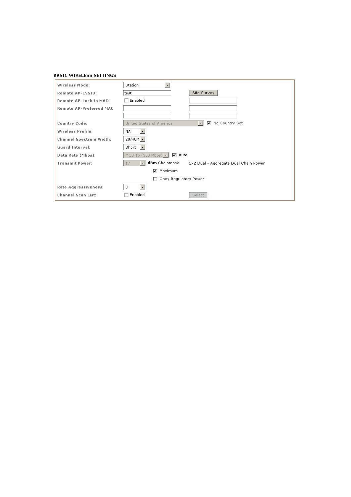
Station Parameters Settings
The options below are only available in Station, Station WDS and Repeater WDS modes unless
otherwise stated.
Wireless Mode: Station
Remote AP-ESSID
This is the Service Set Identifier used by station to seek and connect to the access point of same
the SSID.
Site Survey
Site Survey will search for available wireless networks in range on all the supported channels
and will allow you to select one for association. In case the selected network uses
encryption, you’ll need to set security parameters in the wireless security section. Click Scan
to re-scan the Access Points in range. Select the Access Point from the list and click close this
window. T h e site Survey channel scan list can be modified using the Channel Scan List
control.
Remote AP – Lock to MAC
Enter the MAC address of the remote access point the device is connected to. This option
will make device only connect to this access point.
Remote AP - Preferred MAC
Enter the MAC address of the preferred access point you want t he device to connect t o
when it first starts up. Up to 4 MAC addresses can be entered. Priority is from top to bottom. In
24
IntraTec Solutions Ltd
www.intratec-uk.com
Page 25

the event all preferred MAC addresses are not available the device will then pick the
matching SSID access point with the strongest signal.
Country Code
Different countries have different power levels and also frequency selections. To ensure
the devices operation follows regulatory compliance rules, the operator should make sure that
correct country code where device will be used is selected. The channel list, output power limits,
IEEE 802.11 and Channel Spectrum Width modes will be tuned according to the regulations
of the selected country.
No Country Set:
Option when checked; only these frequency ranges are available.
11n 2.4GHz is 2412-2462MHz, 11n 5GHz is 5180-5320MHz and 5745-5825MHz.
Wireless Profile:
NA is 11n 5GHz band and represents a mixed of 802.11n and 802.11a modes.
NG is 11n 2.4GHz band and represents a mixed of 802.11n, 802.11g and 802.11b modes.
Channel Spectrum Width
20M represents the data transmitted at a bandwidth of 20MHz. 20/40MHz represents the data
transmitted at either 20MHz or 40MHz. In very noisy environments the unit will automatically fall
back to 20MHz to be more resilient to the interference. In a situation when auto fall back does
not happen, manually changing the channel spectrum width to 20MHz will
help
to reduce
interference on the link and improve performance. 10Mhz and 5Mhz widths can also be used to
further reduce interference and improve range. Please note however that a 10Mhz width will
provide approximately ¼ the throughout at 20Mhz and a 5Mhz width will provide approximately
¼ the performance. (Only supported between other units with 10/5Mhz support, all connected
units must be configured with the same channel width)
Note: 40MHz bandwidth is non-standard for 802.11n/g mode, if you experience unstable
performance change the channel width to 20Mhz.
Maximum: checking this box will result in maximum TX output power overriding regulation.
Obey Regulatory Power: checking this box will obey TX output regulatory power by country.
IntraTec Solutions Ltd
www.intratec-uk.com
25
Page 26
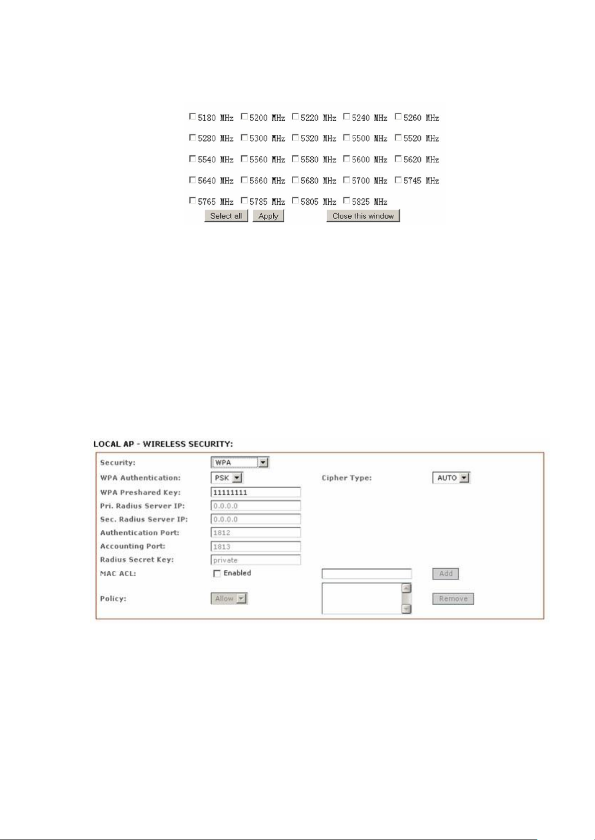
Channel Scan List
Check to enable Channel Scan List. Users can then mark and select only frequencies they want
the device to scan, this will increase scan speed. However, ensure the frequencies selected are
available at the access point end.
Wireless Security
All the wireless security settings are set under this section.
The operation of the keys is the same for ALL the Wireless modes.
WPA or WPA2 Authentication
WPAPSK
PSK (Default): WPA or WPA2 with Pre-shared Key.
IntraTec Solutions Ltd
www.intratec-uk.com
26
Page 27
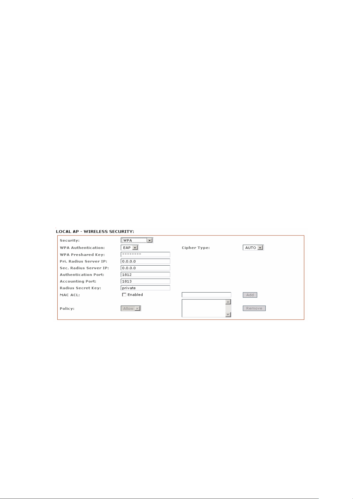
Cipher Type
TKIP: Temporal Key Integrity Protocol which uses RC4 encryption algorithm.
AES: Advanced Encryption Standard (AES) algorithm.
AUTO: Automatically select between both algorithms.
Preshared Key
This option is available when WPA or WPA2, with PSK selected.
The pre-shared key is an alpha-numeric password between 8 and 63 characters long.
Important:
802.11n networks using WPA authentication should use the AES cipher type. Using t he TKIP
cipher type will limit maximum transmission speed to 54Mbps.
WPA + EAP
EAP – WPA or WPA2 with EAP (Extensible Authentication Protocol)
Firmware supported options for clients are: EAP-TTLS, and EAP-PEAP
Cipher Type
TKIP - Temporal Key Integrity Protocol which uses RC4 encryption algorithm.
AES - Advanced Encryption Standard (AES) algorithm.
AUTO (Default) – Automatically select between both algorithms.
Primary Radius Server IP
Enter the Primary Radius Server IP address.
IntraTec Solutions Ltd
www.intratec-uk.com
27
Page 28
Secondary Radius Server IP
Enter the Secondary Radius Server IP address.
Authentication Port
Enter the Authentication Port number of the Radius Server. Default is 1812.
Accounting Port
Enter the Accounting Port number of the Radius Server. Default is 1813.
Radius Secret Key
Enter the Secret Key of the Radius Server. The device uses this to authenticate itself to the
Radius Server.
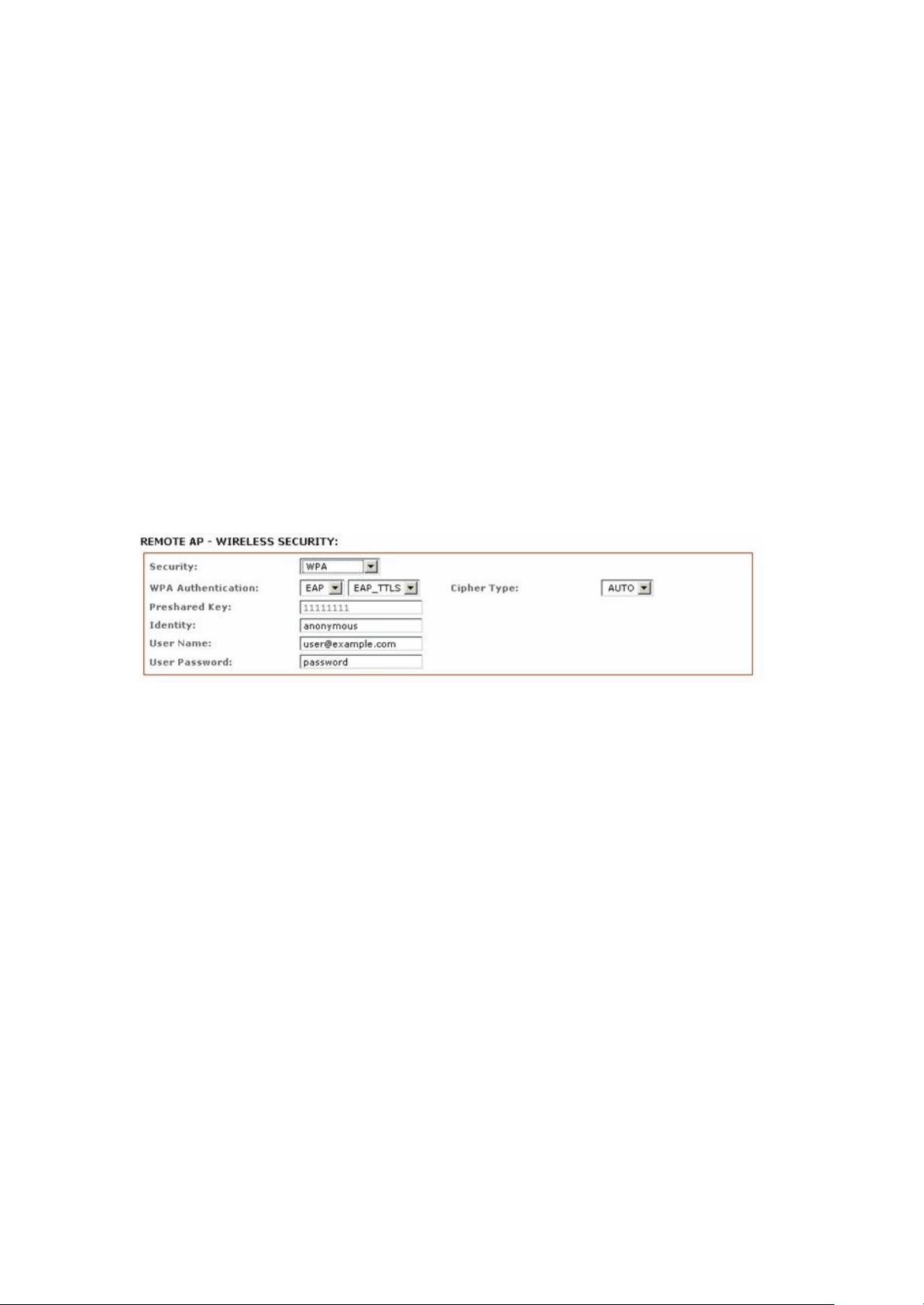
WPA EAP-TTLS and WPA EAP-PEAP
This applies to the following modes only, (when WPA or WPA2, with EAP is selected).
Station, Station WDS, Repeater WDS mode.
Identity
Identification credential used by the wpa-supplicant for EAP authentication.
User Name:
Identification credential used by the wpa-supplicant for EAP tunneled authentication in
unencrypted form.
User Password:
Password credential used by the wpa-supplicant for EAP authentication
IntraTec Solutions Ltd
www.intratec-uk.com
28
Page 29
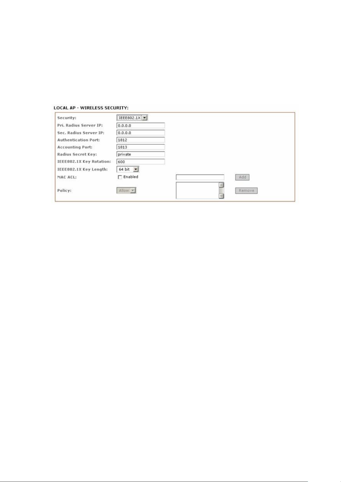
IEEE802.1x Settings
The operation of the Keys is the same for ALL the modes.
Note: Operating with IEEE802.1x security will limit the devices maximum wireless link speed
54Mbps.
These options apply to the following modes only, (when WPA EAP or IEEE802.1x).
Access Point, Access Point WDS, Repeater WDS modes.
Primary Radius Server IP
Enter the Primary Radius Server IP that Access Point will use to query server.
Secondary Radius Server IP
Enter the Secondary Radius Server IP that Access Point will use to query the server.
Authentication Port
Enter the Radius Server Authentication Port number to use. Default is 1812
Accounting Port
Enter Radius server Accounting Port to use. Default is 1813.
Radius Secret Key
Enter Radius server Secret Key that Access Point to use to authenticate itself with radius
server.
IntraTec Solutions Ltd
www.intratec-uk.com
29
Page 30
IEEE802.1x Key Rotation
Enter the time in seconds. After the time expires the device will initiate a key rotation
authentication process for higher security.
IEEE802.1x Key Length
This is the key length of the initial seed key. Select 64 or 128bit.
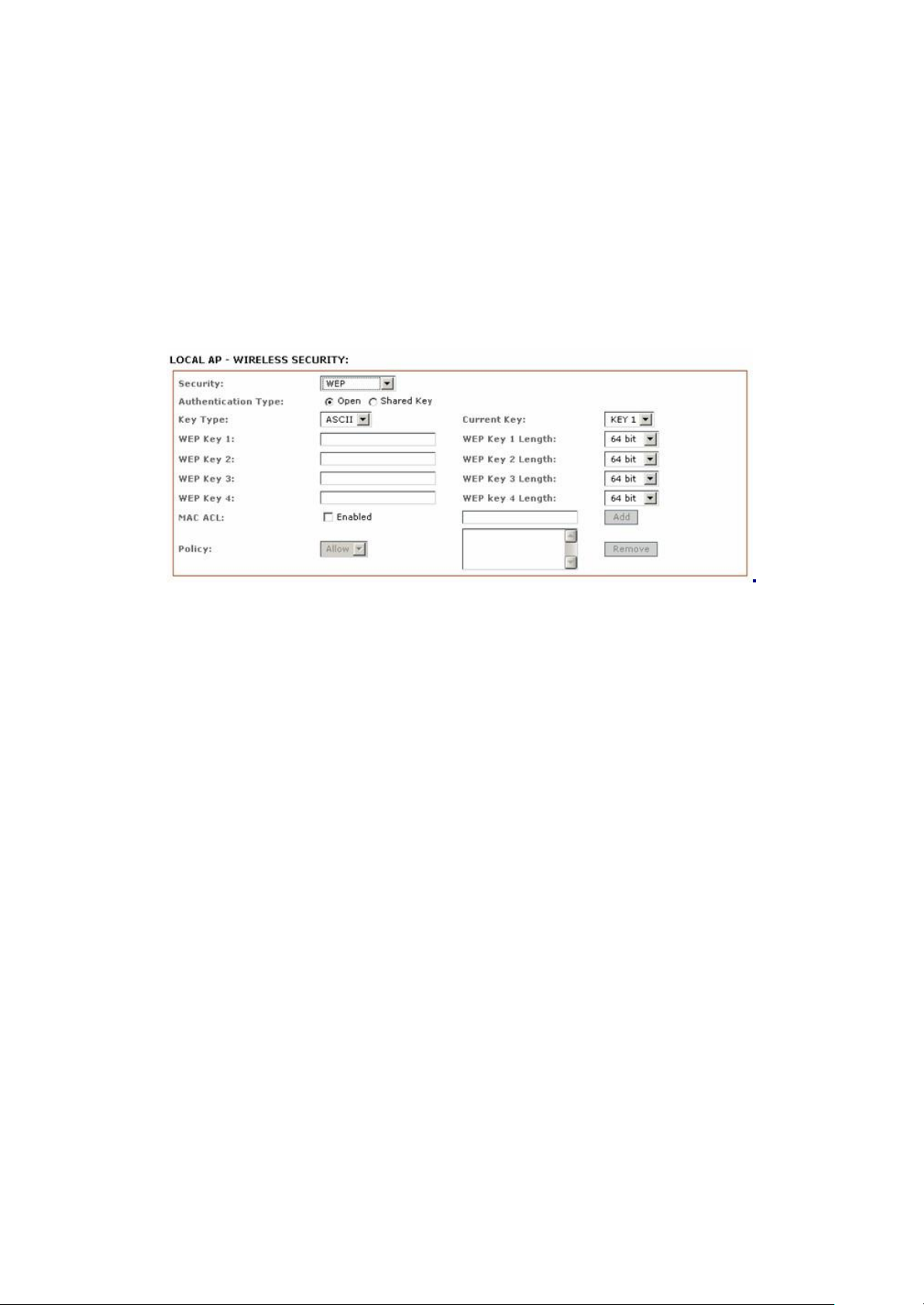
WEP
The operation of the Keys is the same for ALL the modes.
Note: Operating with WEP security will limit the device to maximum wireless link speed of
54Mbps.
Authentication Type:
Open Authentication – (Default) No authentication. Recommend to use this standard option over
shared authentication.
Shared Authentication – May not be compatible with all Access Points. Not recommended.
Key Type:
HEX or ASCII option specifies the character format for the WEP key if WEP security method is
used.
Current Key:
Specify the Index of the WEP Key used. 4 different WEP keys can be configured at the same
time, but only one is used.
WEP Key:
WEP encryption key for the wireless traffic encryption and decryption should be
specified if WEP security method is used.
IntraTec Solutions Ltd
www.intratec-uk.com
30
Page 31
WEP Key Length:
64-bit (selected by default) or 128-bit WEP Key length should be selected if WEP security
method is used. The 128-bit option will provide higher level of security.
For 64-bit – specify WEP key as 5 HEX (0-9, A-F or a-f) pairs (e.g. 00112233AA) or
5 ASCII characters.
For 128-bit – specify WEP key as 13 HEX (0-9, A-F or a-f) pairs
(e.g. 00112233445566778899AABBCC) or 13 ASCII characters.
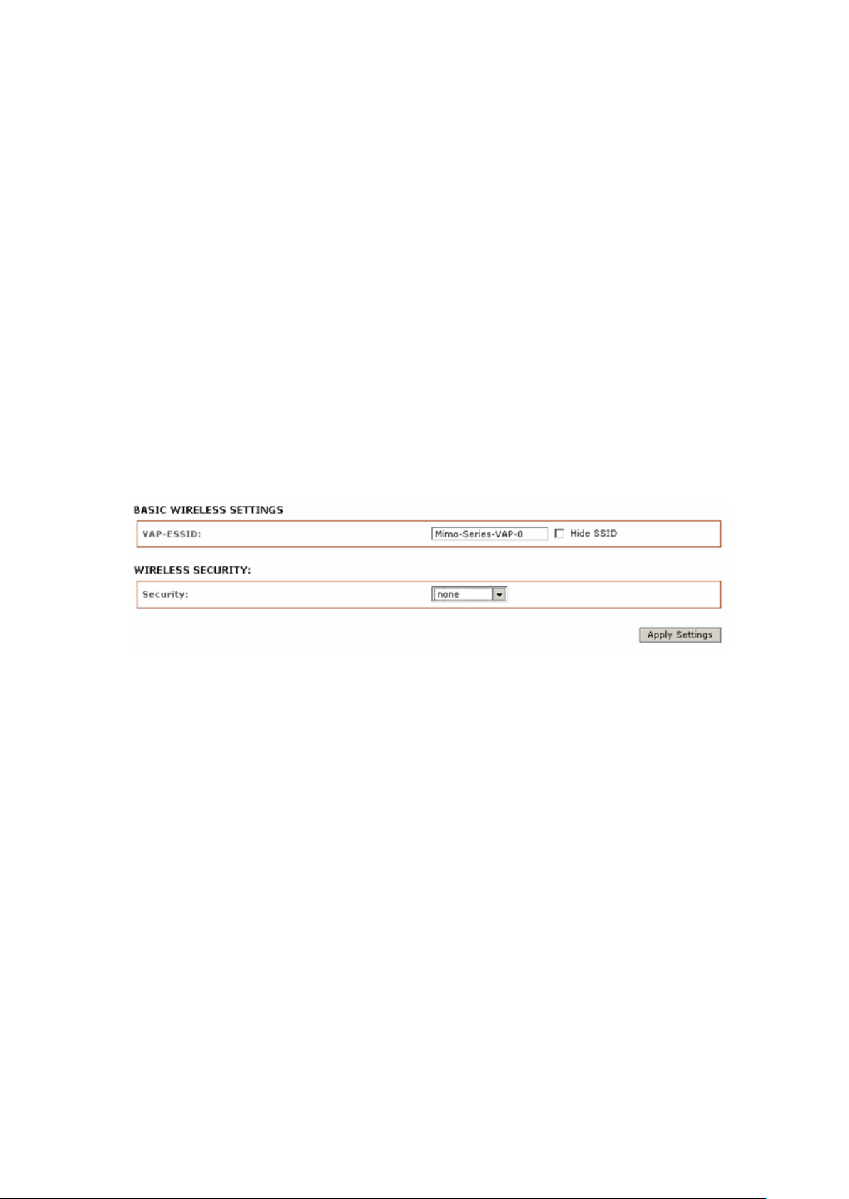
Virtual Access Point (VAP)
Virtual AP (VAP) implements mSSID (Multi-SSID) whereby a single wireless card can be setup
with up to 3 virtual SSID of BSSID connections. Each VAP can be set with different security
authentication mode.
All VAPs are created from the same radio they all share the same wireless channel, country
code, channel spectrum width and transmit power.
Note: Security options like IEEE802.1x and WPA-EAP uses radius server for authentication and
accounting. You may not use different secret keys for each VAP.
IntraTec Solutions Ltd
www.intratec-uk.com
31
Page 32
Advance Wireless
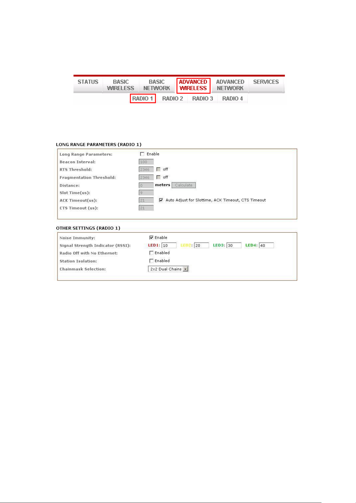
Click Advanced Wireless tab from the menu and select RADIO 1 or RADIO 2 to open the page
below.
Long Range Parameters Setup
The advanced wireless page optionally lets you optimize the link for a specific distance. These
options are for fixed point to point links only and should only be used by advanced users.
Long Range Parameters:
Check to enable parameters.
Beacon Interval: (default is 100 MS)
Define the time interval (in milliseconds) for the beacon to be broadcast. We recommend using
the default value.
Distance:
Enter the distance in meters between both devices. Then click Calculate. The close
approximate values for Slot Time, ACK Timeout, and CTS Timeout will be calculated to
achieve the best possible performance and link reliability.
IntraTec Solutions Ltd
www.intratec-uk.com
32
Page 33

RTS Threshold:
The range is 0-2347bytes, or the word “off”. The default value is
2347 which means that RTS is disabled.
RTS/CTS (Request to Send / Clear to send) are the mechanisms used by the 802.11 wireless
networking protocols to reduce frame collisions introduced by the hidden terminal problem. If
the packet size the node wants to transmit is larger than the threshold, the RTS/CTS handshake
gets triggered. If the packet size is equal to or less than threshold the data frame gets sent
immediately.
Fragmentation Threshold:
specifies the maximum size for a packet before data is fragmented into multiple packets. The
range is 256-2346 bytes, or the word “off”. Setting the Fragmentation Threshold too low may
result in poor network performance.
The use of a fragmentation threshold can increase reliability because when sending smaller
frames collisions are much less likely to occur, however lower values will result lower
throughput as well. The default setting of 2346 is optimum for most network use cases.
Acknowledgement Timeout:
The device has an auto-acknowledgement timeout algorithm which dynamically optimizes the
frame acknowledgement timeout value without user intervention. This is a critical feature
required for stabilizing long-distance outdoor links.
Distance:
Specify the distance value in miles (or kilometers) using the slider or enter the value manually.
Changing the distance value will change the ACK Timeout to the appropriate value of the
distance.
ACK Timeout:
specify the ACK Timeout. Every time the device receives the data frame it sends an ACK frame
to the sender (if transmission errors are absent). If the sender receives no ACK frame from the
device within a set timeout it re-sends the frame. If too many data frames are re-sent (the
timeout is set too short or too long) it will result in poor throughput and performance.
Auto:
If enabled the ACK Timeout value will be derived dynamically. It is not recommended to use
Auto Adjust option for long range links if the signal level is low or a high level of interference is
present. If two or more stations are located at considerably different distances from the device
in Access Point mode the highest ACK Timeout for the farthest station should be set at the AP
side. It is not recommended to use Auto Adjust option for Point-to-Multipoint connections.
IntraTec Solutions Ltd
www.intratec-uk.com
33
Page 34
Noise Immunity:
Check to enable. When enabled the device will automatically adjust the noise to signal ratio
for best performance. In low noise environments it is recommended to turn off this function.
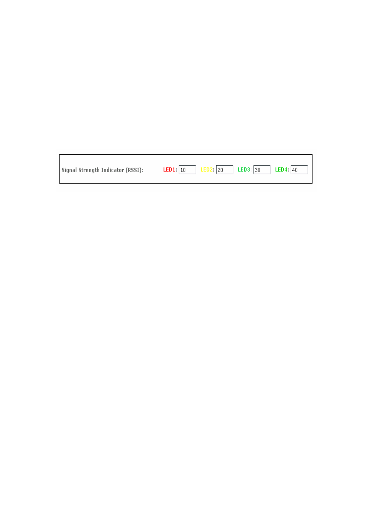
Signal Strength Indicator (RSSI):
Note: The signal strength meter will always display 5 bars when in Access Point or Router
modes. Only devices set in Station or Client modes will display signal strength.
The default values are LED1 (RSSI value=7), LED2 (RSSI value=15), LED3 (RSSI value=22), LED4
(RSSI value=27)
Radio Off with No Ethernet:
When checked the unit automatically stops wireless broadcast when the Ethernet link is down.
Station Isolation:
When checked the device prevents wireless clients on same AP from discovering other clients.
When enabled wireless stations connected to the same AP will not be able to interconnect on
both layer 2 (MAC) and layer 3 (IP) level. This is effective for the associated stations and WDS
peers also.
IntraTec Solutions Ltd
www.intratec-uk.com
34
Page 35
Chain Mask Selection:
Available selections are: a) 1x1 Left Chain, b) 1x1 right Chain and c) 2x2 Dual Chain
Selecting 1x1 (Left/Middle/Right) Chain will force the radio card to operate with 1transmit and 1
receive stream and both transmit /receive on the left, middle or right port only.
Selecting 2x2 Dual Chain will enable radio card to operate with 2 transmit and 2 receive streams
and automatically transmit / receive on any of the 2 ports.
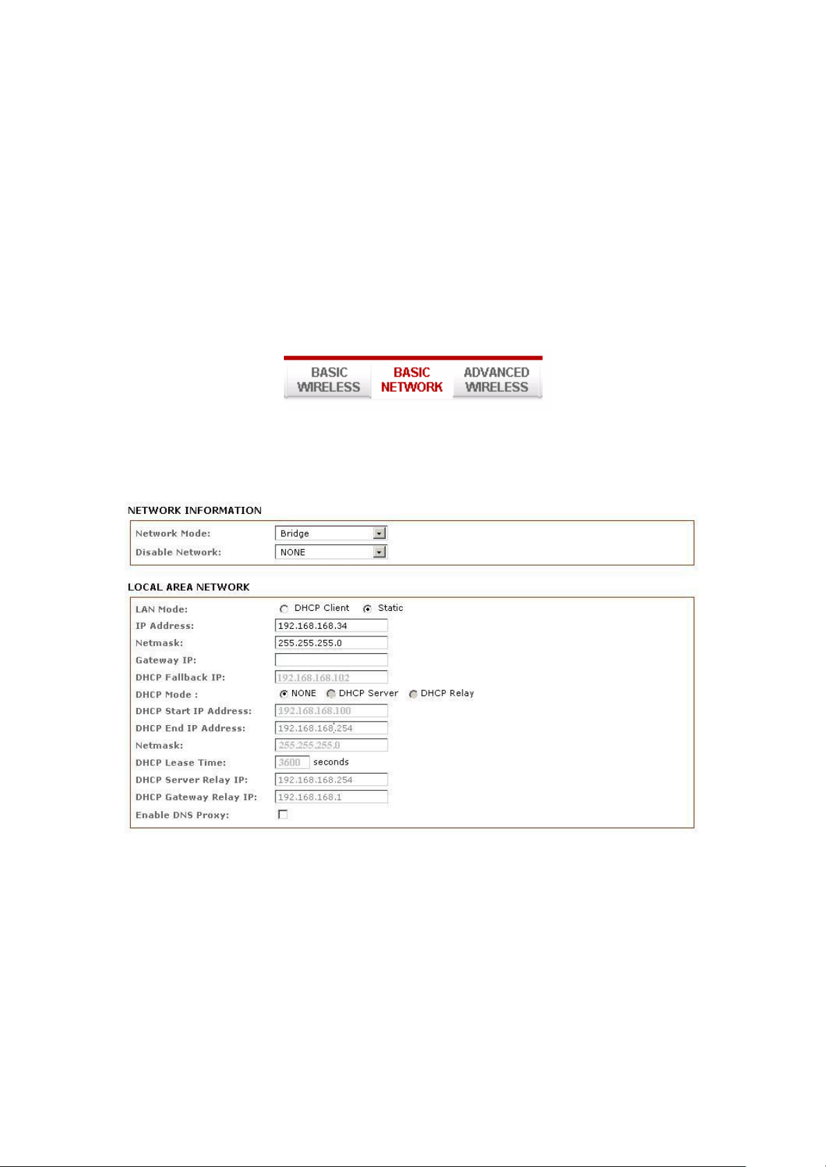
Basic Network
Click BASIC NETWORK from the menu bar to open the page as shown below.
IntraTec Solutions Ltd
www.intratec-uk.com
35
Page 36

Network Mode: Bridging and Routing
Network Mode:
Select between Bridge (default) and Router mode.
LAN Setup
LAN Mode:
Static: (default) lets you enter a specific IP address for the device.
Default IP address is 192.168.168.1
DHCP Client: when set the device will learn its IP address automatically from an existing DHCP
server.
Netmask:
Let’s you set the class for the IP address. The default is class C (24 bit mask) 255.255.255.0
Gateway: (optional)
Enter the gateway IP address of the network the device is connected to if a gateway exists.
DHCP Fallback IP:
Should the device be in DHCP Client mode and fail to obtain an IP address from the DHCP server
the user can access the device using this temporary fallback IP address.
DHCP Mode:
None: function disabled
DHCP Server: When enabled the device acts as an IP address distribution server so will
automatically issue IP address and other network information to the DHCP Clients.
DHCP Relay: check to enable. Enter the IP address of the remote DHCP server where the DHCP
Client request will be relayed to.
DHCP Start IP Address:
Enter the starting IP address to be issued.
DHCP End IP Address:
Enter the last IP address the server will issue.
DHCP Lease Time: (default is 3600 seconds or 1hour) Enter the new lease time in seconds.
IntraTec Solutions Ltd
www.intratec-uk.com
36
Page 37
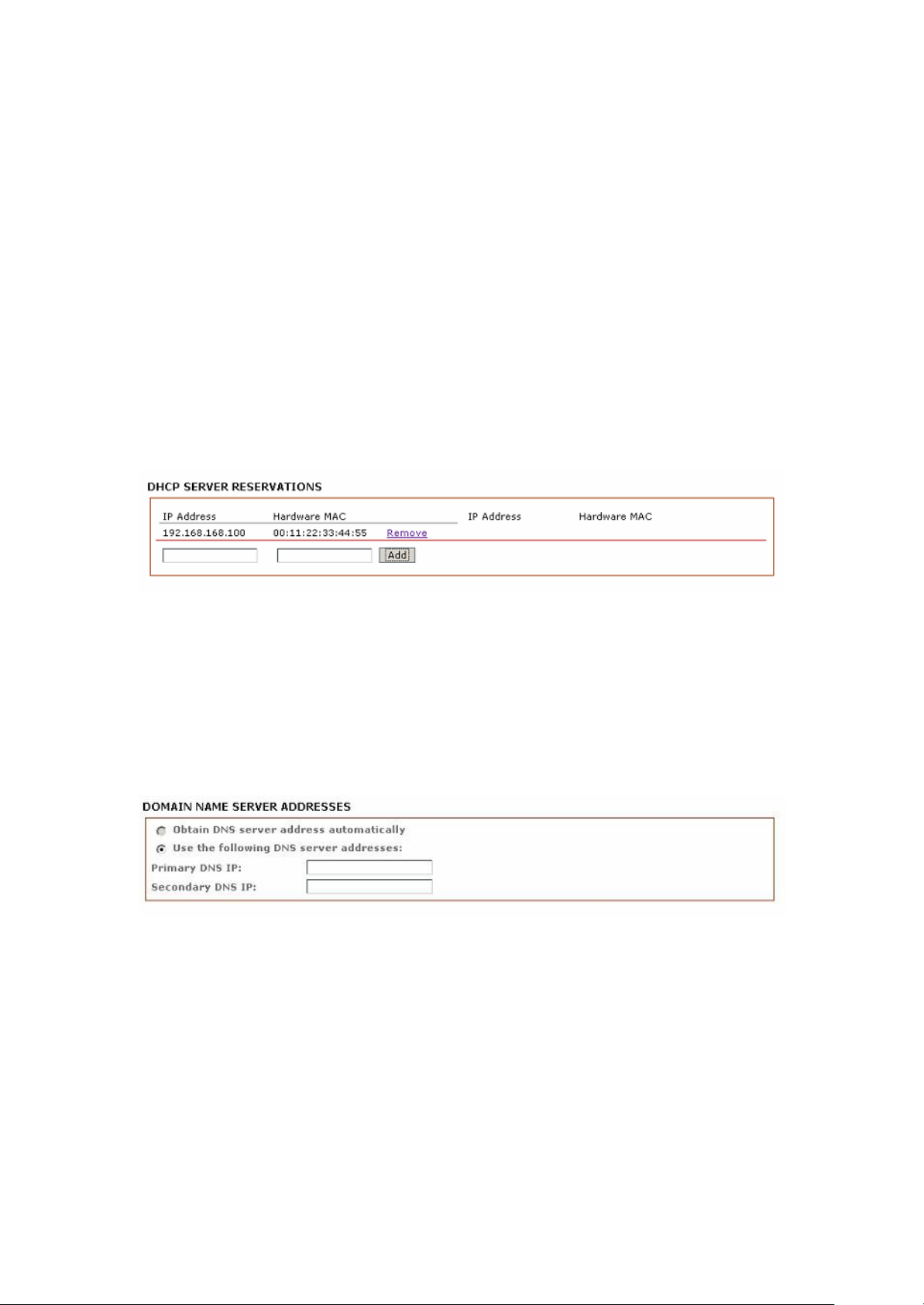
DHCP Server Relay IP:
Enter the IP address of the remote DHCP server where the DHCP Client request will be
relayed to get the IP address.
DHCP Gateway Relay IP:
Enter the IP address of the remote gateway where the DHCP Client request will be relayed
to, to get the gateway IP address.
Enable DNS Proxy:
Check to enable this function. When enabled the device in router mode will act as proxy to
resolve all DNS requests.
DHCP Reservations
Click Add to enter each devices IP and MAC address.
All active DHCP leases are displayed in the Status tab page from u n d e r the More
Status selection.
Domain Name Server Entry
The Primary and Secondary DNS IP addresses allow the device to resolve domain names in
order to reach certain servers like the internet time server and other services that use domain
names.
Note: Ensure device gateway IP is also set to allow device to access to internet.
Primary DNS IP: (optional)
Enter the primary DNS IP address
IntraTec Solutions Ltd
www.intratec-uk.com
37
Page 38

Secondary DNS IP: (optional)
Enter the secondary DNS IP address
Bandwidth Control between Ethernet and Wireless
An entry of value “0” means no bandwidth flow limit between the 2 interfaces.
An entry of “2000” means 2000Kbit or 2Mbit limit traffic flow between the two interfaces.
Default is “0”
IntraTec Solutions Ltd
www.intratec-uk.com
38
Page 39
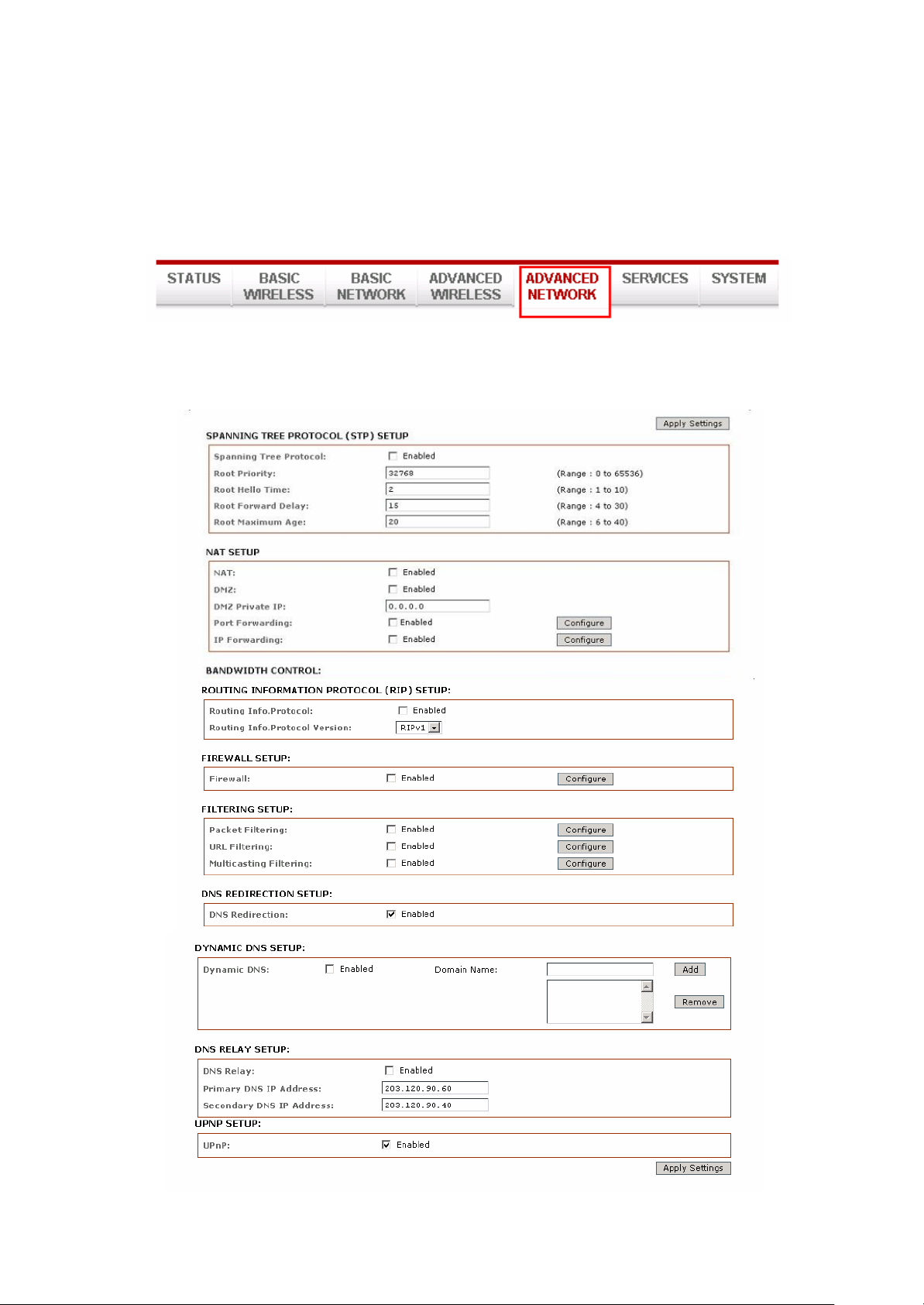
Advanced Network
Note: This tab will not be visible when in device is in Bridge mode, only in router mode.
IntraTec Solutions Ltd
www.intratec-uk.com
39
Page 40
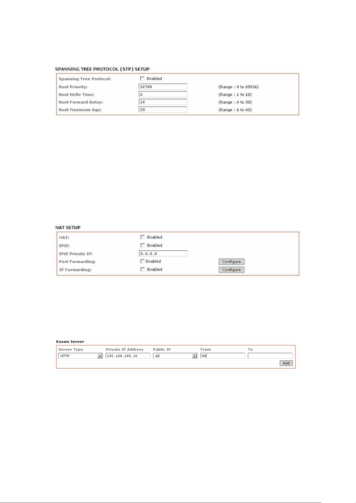
Spanning Tree Setup
Spanning Tree Protocol: Default is disabled. Check on box to enable.
Root Priority: Default value is 32768. Smaller value has higher priority.
Root Hello Time: Default time is 2 seconds. Root Forward Delay: Default is 15 seconds Root
Maximum Age: Default is 20 seconds
Changing to a lower time can cause high overheads on the network.
NAT Setup
NAT: Enabled when in Router mode, disabled when in Bridge mode.
DMZ: Default is disabled. Check on box to enable.
DMZ IP Address: Input the IP address of the local PC to receive the DMZ packets. Port
Forwarding: Default is disabled. Check on box to enable.
IntraTec Solutions Ltd
www.intratec-uk.com
40
Page 41
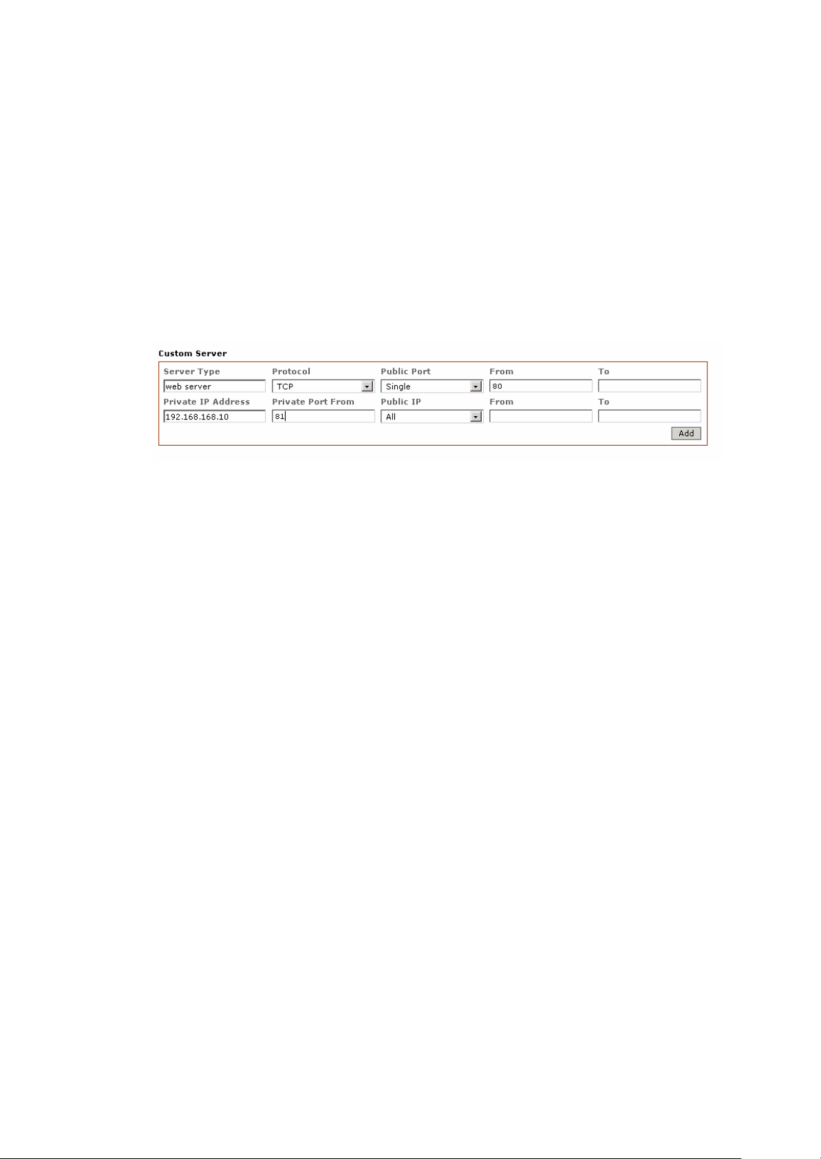
Adding an entry from Known Server
Add an entry from this box and select an application from the list.
Server Type: click to select the application you want to add.
Private IP Address: Enter the local IP of the PC running the application
Public IP Address: To open the port to any people on the internet then select the default, All.
To open to only a specific IP, select Single and enter the IP address.
To open to only a specific range of IPs, select Range and enter IP address range.
Adding an entry from Custom Server
The Custom Server box lets you enter a new port number for an application or add new
applications.
Server Type: Enter a brief name for the application.
Protocol: Select TCP or UDP
Public Port: select Single or Range
From: if a single port use this box only. If a port range enter the starting port number here.
To: if a single port, leave blank. If a port range enter the last port number here.
Private IP Address: Enter the local IP of the PC running the application
Private Port From: If a single port, enter same public port number or new port number.
If a port range, enter only the starting port number.
Public IP Address: To open the port to any people on the internet then select the default, All..
To open to only a specific IP, select Single and enter the IP address.
To open to only a specific range of IPs, select Range and enter IP address range.
IntraTec Solutions Ltd
www.intratec-uk.com
41
Page 42
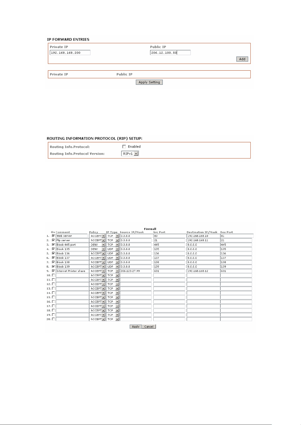
IP Forwarding: Default is disabled. Check on box to enable.
Private IP: enter the local IP address to receive the forwarded packets from the public IP
Public IP: enter the public IP address that when accessed will forward all the packets to the
local IP Click Add to add to list.
Routing Information Protocol: Default is disabled. Check on box to enable.
Router Info Protocol version: select RIPv1 or RIPv2
Firewall Setup
Firewall Setup: Default is disabled. Check box to enable..
Comment: enter a brief name for the service.
Policy: select Accept or Deny for the apply rule
IntraTec Solutions Ltd
www.intratec-uk.com
42
Page 43
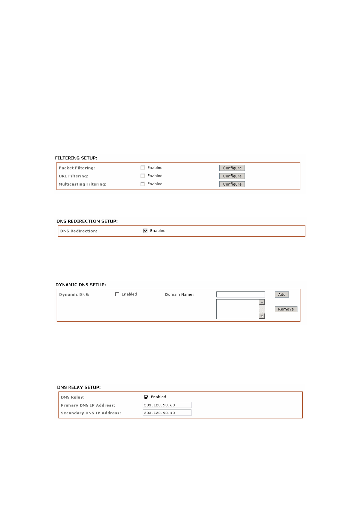
IP Type: select ICMP, TCP, and UDP packet type
Source IP/Mask: enter the source IP address and Netmask
Src Port: enter the source port number in the rule check
Destination IP/Mask: enter the destination IP and Netmask
Des Port: enter the destination port in rule check
Click Apply to save the rule or Cancel to clear the rule set.
Outbound Filtering Setup
Filtering Setup: Default is disabled. Check box to enable.
DNS Redirection:
Default is enabled. Check box to disable. When enabled the device will act as a DNS proxy.
Devices connected to this device set their DNS IP to router’s IP address.
Dynamic DNS Setup:
Default is disabled. Check box to enable. Dynamic DNS lets the router’s WAN dynamic IP
address be linked and automatically updated to a domain name server hosting the service. This
ensures users on the internet can always access the hosting services behind the device in
router mode.
DNS Relay Setup:
Default is disabled. Check box to enable. These are the primary and secondary DNS IPs the
IntraTec Solutions Ltd
www.intratec-uk.com
43
Page 44

devices proxy service will use to resolve the domain names on behalf of connected clients.
Primary DNS IP Address: Enter the primary DNS IP address
Secondary DNS IP Address: Enter the secondary DNS IP address
UPNP:
Default is disabled. Check box to enable. When enabled, devices running UPnP services can
automatically open certain specific ports. For security reasons this service should generally not
be enabled, instead we recommend manually opening required ports through the port
forwarding service.
IntraTec Solutions Ltd
www.intratec-uk.com
44
Page 45
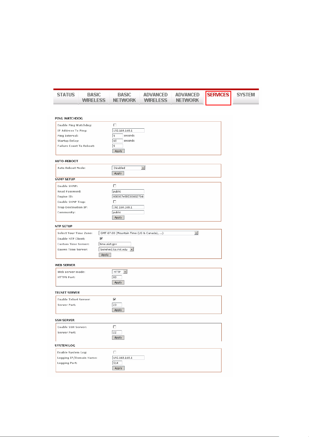
Services Tab
Click the Services tab from the menu to open the page below.
IntraTec Solutions Ltd
www.intratec-uk.com
45
Page 46
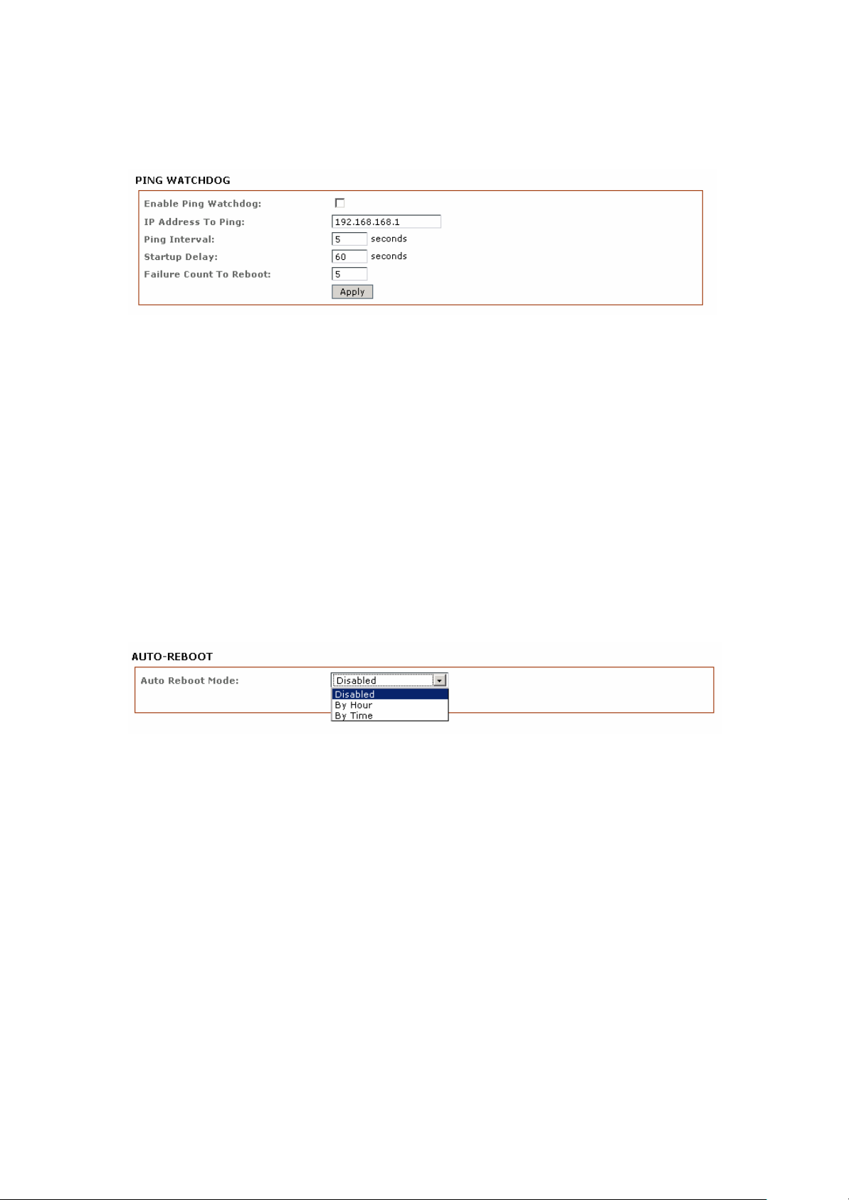
Ping Watchdog
Enable Ping Watchdog: Default is disabled. Check box to enable.
IP Address To Ping: Target IP address for the test monitor.
Ping Interval: Default is 5 seconds (minimum). This is the Ping test duration.
Startup Delay: Default is 60 seconds (minimum).
One time delay after device startup.
Failed Count to Reboot: Default is 5. This is the number of ping failures before the device starts
the reboot process.
Auto-Reboot
Auto-Reboot Mode: Default is disabled. Select by Hour or By Time check.
This mode lets you preset a timer to automatically force a reboot. The timer can operate on a
fixed number of hours or at a specified time of day.
By Hour: Enter the number of hours the device needs to run before starting the reboot process.
By Time: Enter the specific time of day in hh:mm (24-hour format) before starting the
reboot process.
46
IntraTec Solutions Ltd
www.intratec-uk.com
Page 47
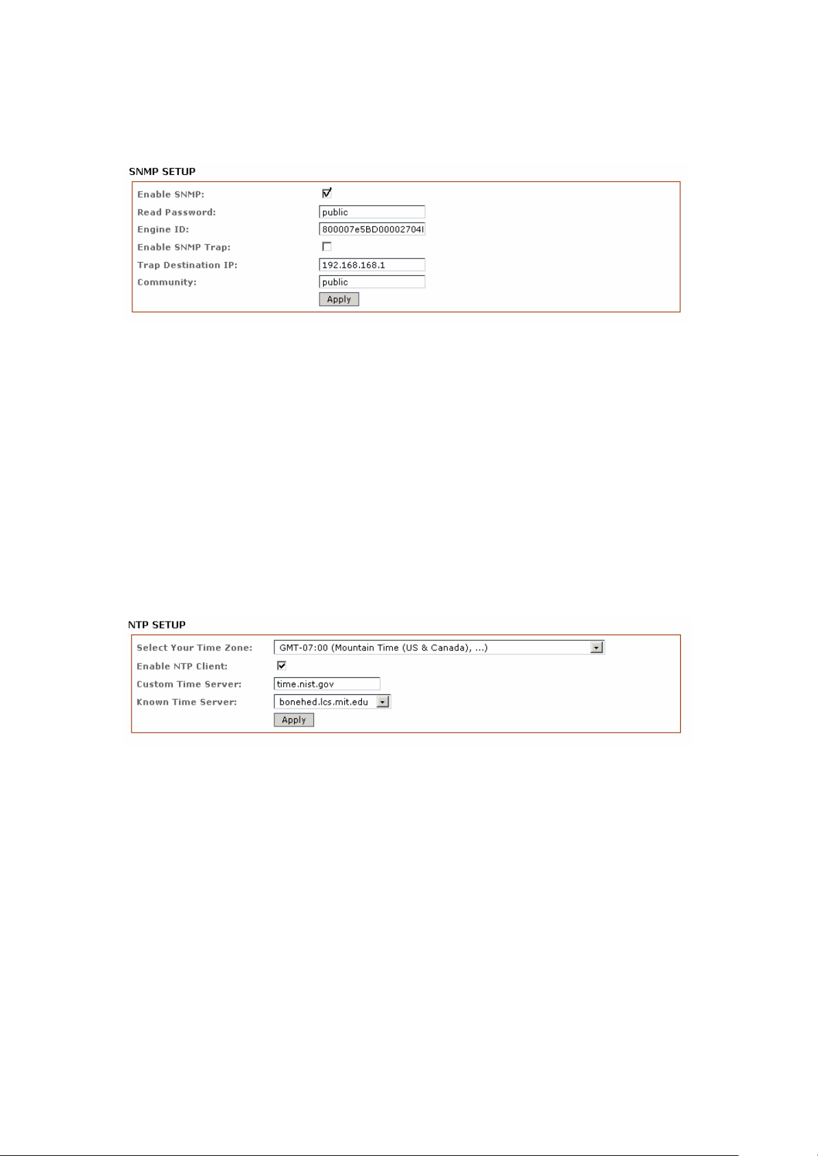
SNMP Setup
Enable SNMP: Default is disabled. Check box to enable.
Read Only Password: Password to query device.
Engine ID: Default is 800007e5BD00002704D000007c
Enable SNMP Trap: Default is disabled. Check box to enable.
Trap Destination IP: Enter the IP to send the info to when the trap is triggered.
Community: Enter the SNMP community string.
NTP Setup
Enable NTP Client: Default is disabled. Check box to enable.
Select Your Time Zone: Select the country in which you reside.
Custom Time Server: Default is “time.nist.gov“Enter preferred time server domain or IP
Known Time Server: You can also select one from this list as your new time server.
IntraTec Solutions Ltd
www.intratec-uk.com
47
Page 48
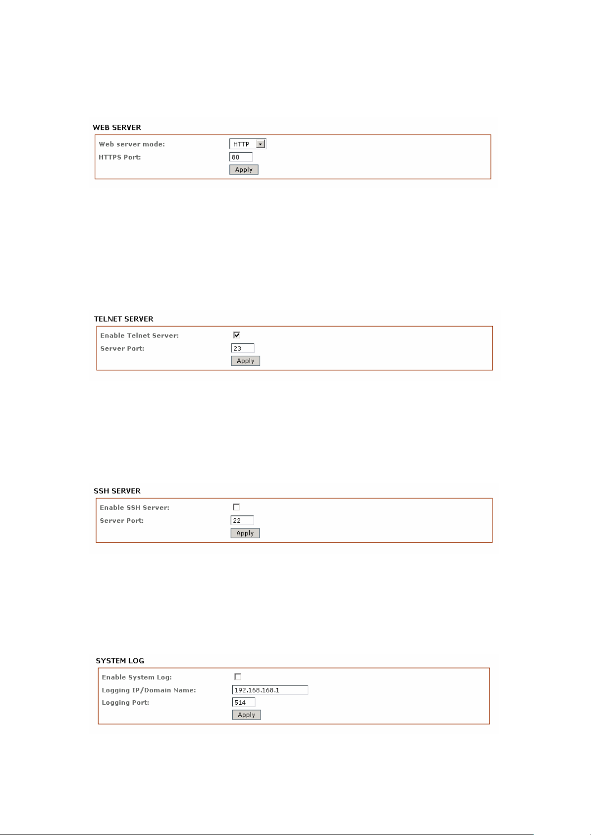
Web HTTP Security
Web Server Mode: Default is HTTP. Option is HTTP and HTTPs
HTTP(s) Port: Default is 80 for HTTP and 413 for HTTPs.
Enter a new preferred port number.
Telnet Access Setup
Enable Telnet Server: Default is enabled. Uncheck box to disable.
Server Port: Default is 23. Enter new preferred port number.
SSH Access Setup
Enable SSH Server: Default is disabled. Check box to enable.
Server Port: Default is 22. Enter new preferred port number.
System Log Setup
IntraTec Solutions Ltd
www.intratec-uk.com
48
Page 49
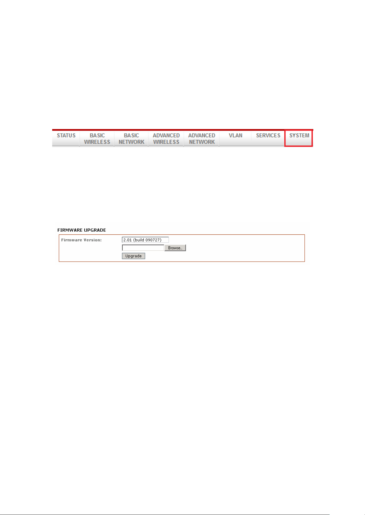
Enable System Logging: Default is disabled. Check box to enable.
Logging IP /Domain Name: Enter the destination IP address of the device you want to receive
the log.
Logging Port: Default is 514. Enter the new preferred port number.
System Tab
The System Page contains Administrative options. This page enables administrators to reboot
the device, set it to factory defaults, upload a new firmware, backup or update the
configuration and configure administrator’s credentials.
Firmware Upgrade
Use this section to find out current software version and update the device with new firmware.
System configurations are preserved when the device is updated with a new firmware version.
Firmware version: displays the version of the current firmware.
Upgrade: button opens the Firmware Upload window.
Firmware File: click the browse button to navigate to and select the new firmware file. The new
firmware file is transferred to the systems memory after the Upload button is activated.
Close this window – button cancels the new firmware upload process.
Upgrade button should be activated in order to proceed with the firmware upgrade routine the
(new firmware image should be uploaded into the system first). Please be patient, as the
firmware upgrade routine can take 3-7 minutes. The device will be un-accessible until the
firmware upgrade routine is completed.
It is highly recommended to back up the system configuration before uploading the new
configuration.
Close this window – button closes the firmware upgrade window.
IntraTec Solutions Ltd
www.intratec-uk.com
49
Page 50
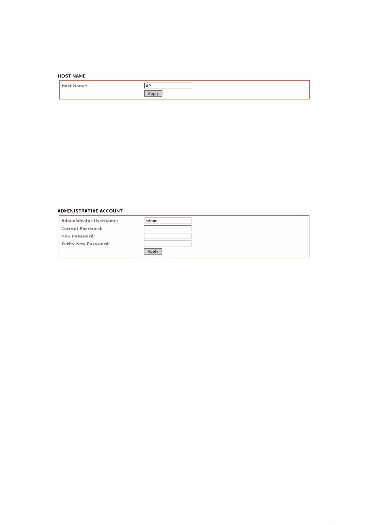
Host Name
The Host Name is the system wide device identifier. It is reported by the SNMP Agent to
authorized management stations. The Host Name will be represented in popular Router
Operating Systems registration screens and discovery tools.
Host Name: specifies the system identity.
Change button saves the Host Name.
Administrative and
In this section you can modify the administrator password. The default administrator’s
password should be changed on the very first system setup:
Read-only
Account
Administrator Username: specifies the name of the user.
Current Password: the administrator is required to enter a current password. It is required for
password or Administrator Username change routines.
Default administrator login credentials:
User Name: admin
Password: password
New Password: the new password used for administrator authentication should be specified.
Verify Password: the new password should be re-entered to verify its accuracy.
Click Change button to save the changes.
IntraTec Solutions Ltd
www.intratec-uk.com
50
Page 51
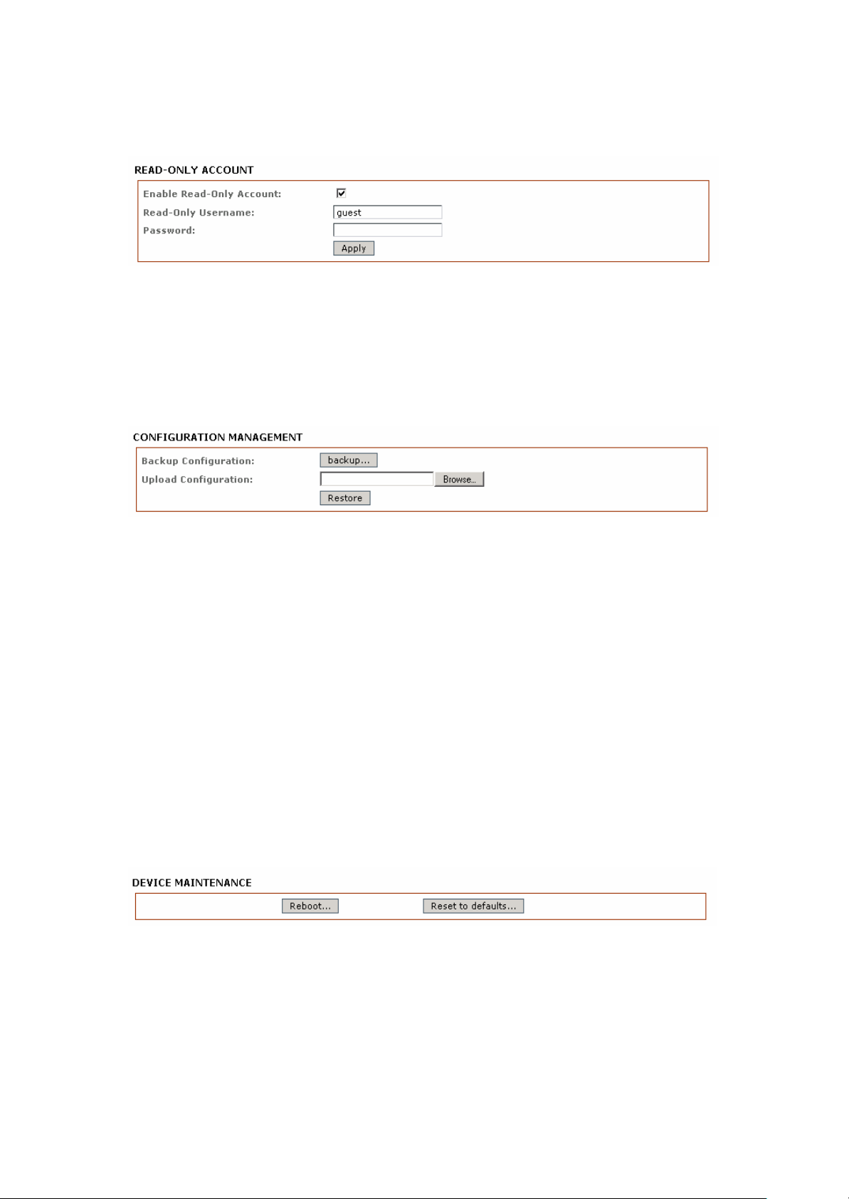
Enable
Read-Only
Account
Read-Only Username: new username for the read-only administrator should be specified.
Password: new password used for the read-only administrator should be specified.
Configuration Management
Backup Configuration: click the Download button to export the current configuration to a file.
Upload Configuration: click the Browse button to navigate to and select the new
configuration file.
Clicking the Upload button will transfer the new configuration file to the system.
The new configuration will be effective after the Apply button is activated and the system
reboot cycle is completed. It is highly recommended to back up the system configuration
before uploading a new configuration.
Use only configuration backups of the same type device - configuration backed up from Bridge
Duo units are not compatible with standard Bridge units and vice versa.
Device Maintenance
The controls in this section are for performing device maintenance routines:
Reboot: activate the Reboot control in order to initiate a full reboot cycle of the device. The
system configuration is not modified after the reboot cycle completes. Any non-applied
changes however will be lost.
IntraTec Solutions Ltd
www.intratec-uk.com
51
Page 52
Reset to Defaults: activate the Reset to Defaults control in order to initiate a reset to factory
defaults routine. The running system configuration will be deleted and the default system
configuration (all the system settings with no exception) will be set.
After the Reset to Defaults routine is completed, the device system will return to the default IP
configuration (192.168.168.1/255.255.255.0) and will start operating in Station-Bridge mode. It
is highly recommended to back up the system configuration before the Reset to Defaults
routine is initiated.
VLAN Tab
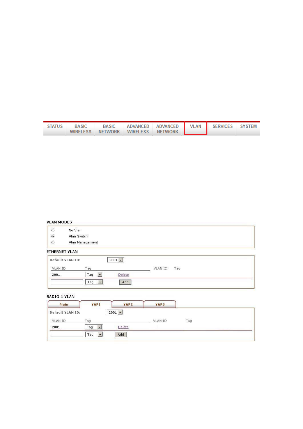
This page lets you create virtual local network connections through the devices Ethernet and
wireless connections.
By default VLAN mode is disabled (No Vlan is checked)
VLAN Switch
To setup a VLAN network check the Vlan Switch box
To add a Tag VLAN ID for Ethernet port, type in the ID number select Tag and click Add
To add a Tag VLAN ID for MAIN wireless SSID, type in the ID number select Tag and click Add To
add a Tag VLAN ID for VAP1 wireless SSID, type in the ID number select Tag and click Add To add
a Tag VLAN ID for VAP2 wireless SSID, type in the ID number select Tag and click Add To add a
52
IntraTec Solutions Ltd
www.intratec-uk.com
Page 53
Tag VLAN ID for VAP3 wireless SSID, type in the ID number select Tag and click Add
Warning: Adding a Tag VLAN ID can cause a loss of connection to devices web manager if the
PCs Ethernet port or wireless connection does not have a Tag VLAN ID or does not have the
same VLAN ID setup. If this case use the devices Reset button to clear the config and
reconfigure. Refer to the Reset button operations section.
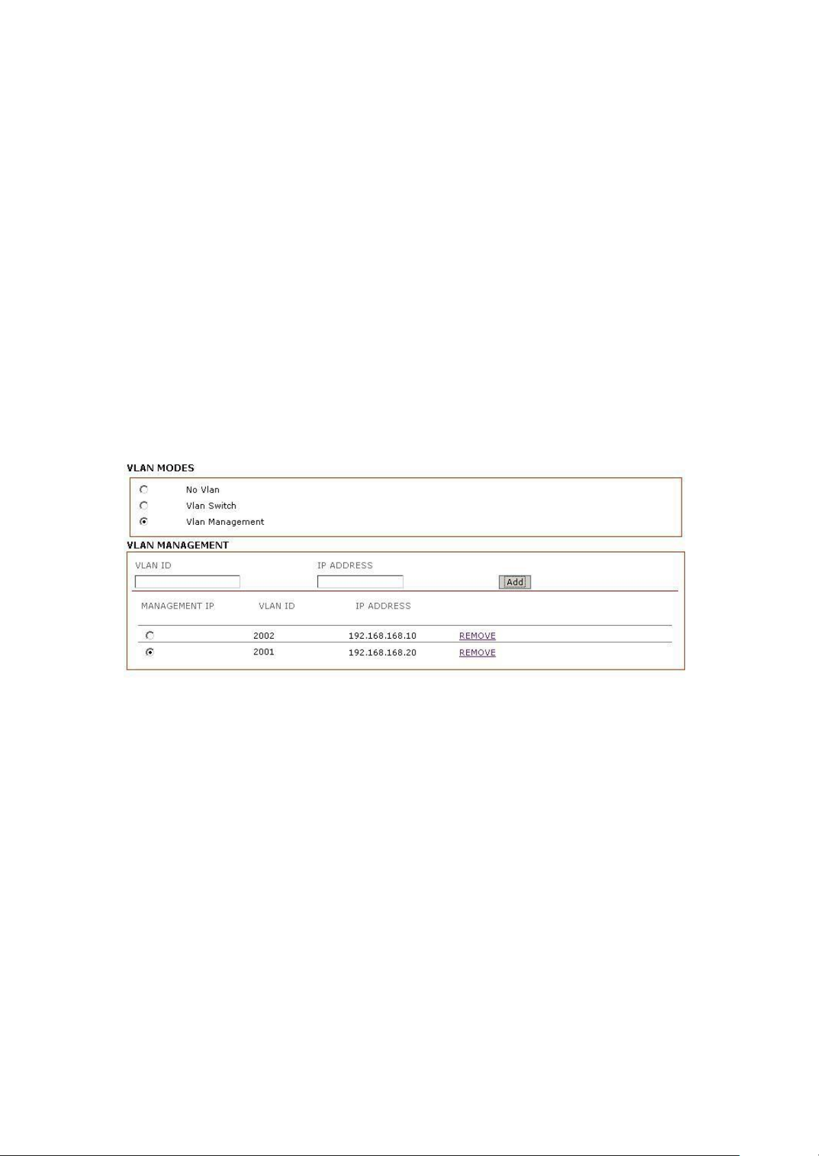
VLAN Management
Vlan management lets you control and limit the client connections that can open the devices
web page.
Note: Vlan Management works only in tag vlan pass-through mode. i.e. when Vlan Switch is
disabled. When Vlan Switch is enabled or configured, Vlan Management function stops
operating.
Example:
Assuming there are 2 VLAN ID groups, 2001 and 2002 setup on the device. One entry in the
Vlan Management has the Vlan ID 2001 with masquerade IP address 192.168.168.20, another
entry in Vlan Management has the Vlan ID 2002 with masquerade IP address 192.168.168.10
You can only select one of the 2 entries to be the active Vlan ID and IP address. If t h e Vlan ID
2001 group is selected, then only computers in that Vlan ID group can open the devices web
page using the IP address, 192.168.168.20 if there is no entry in Vlan Management, there is
no restriction. All computers can open the devices web page by the default IP address setup in
Basic Network page
IntraTec Solutions Ltd
www.intratec-uk.com
53
IntraTec Solutions Ltd
www.intratec-uk.com
Page 54

54
IntraTec Solutions Ltd
www.intratec-uk.com
Page 55

55
 Loading...